microstructure and hardness studies of electron beam ...dl.iran-mavad.com/sell/trans/en/electron...
TRANSCRIPT

lable at ScienceDirect
Vacuum 110 (2014) 121e126
Contents lists avai
Vacuum
journal homepage: www.elsevier .com/locate/vacuum
Microstructure and hardness studies of electron beam welded Inconel625 and stainless steel 304L
M. Shakil a, b, *, M. Ahmad b, N.H. Tariq c, B.A. Hasan c, J.I. Akhter b, E. Ahmed b,M. Mehmood c, M.A. Choudhry a, M. Iqbal b
a Department of Physics, The Islamia University of Bahawalpur, Bahawalpur 63100, Pakistanb Physics Division, Pakistan Institute of Nuclear Science & Technology, P.O. Nilore, Islamabad, Pakistanc DMME, Pakistan Institute of Engineering and Applied Sciences, P.O. Nilore, Islamabad, Pakistan
a r t i c l e i n f o
Article history:Received 19 April 2014Received in revised form27 August 2014Accepted 28 August 2014Available online 16 September 2014
Keywords:Inconel 625SS 304LElectron beam welding (EBW)Fusion zoneScanning electron microscopy (SEM)
* Corresponding author. Department of Physics, Thwalpur, Bahawalpur 63100, Pakistan. Tel.: þ92 321 68
E-mail addresses: [email protected], m.shakhotmail.com (M. Shakil).
http://dx.doi.org/10.1016/j.vacuum.2014.08.0160042-207X/© 2014 Elsevier Ltd. All rights reserved.
Downloaded from http://www.elearn
a b s t r a c t
In this study, electron beam welding of dissimilar Inconel 625 and SS 304L alloys was successfullyperformed by employing optimized electron beam welding parameters. The welded joint was charac-terized using SEM/EDS, XRD and micro-hardness tester. The welded joint was found homogeneous, wellbonded and defect free. Two types of microstructure i.e. columnar dendritic and cellular dendritic wereobserved in the fusion zone. The development of different microstructures in the fusion zone wasattributed to the localized cooling effects during solidification. Few micro-cracks along with dendritessplitting were observed in the vicinity of end crater that was mainly due to the segregation of S element.A significant variation of Ni and Fe was observed across Inconel/FZ and FZ/SS interfaces due to their fastdiffusion in the melt pool. Micro-hardness measurements across Inconel/FZ and FZ/SS interfaces showedan increasing trend in the FZ from SS 304L towards Inconel base alloy.
© 2014 Elsevier Ltd. All rights reserved.
1. Introduction
Welding of dissimilar materials has been the subject of interestof many researchers due to their high demand for various industrialapplications. Dissimilar materials are welded in order to increaseflexibility in design and application. However, this practice mayoften create problems that severely affect the performance duringservice. The welding of two dissimilar alloys with different thermalexpansion coefficient, melting temperature is a complicated task[1,2]. Inconel 625 is a Nickel base superalloy strengthened by a solidsolution of molybdenum and niobium in its nickelechromiummatrix. It has wides pread applications in aerospace, marine,chemical, petrochemical industries due to its superior physical andchemical properties i.e high strength, corrosion and creep resis-tance at elevated temperatures. The alloy has also some applica-tions in nuclear power plant reactor-core and control rodcomponents of pressurized water reactor. It is also being used as aheat exchanger tube in ammonia cracker plants of heavy water
e Islamia University of [email protected], shakil101iub@
ica.ir
production [3,4]. Stainless steel 304L is a less expensive structuralmaterial that found applications within general corrosive envi-ronments, reprocessing plants and nuclear power plant compo-nents. During welding process its lower carbon content reduces theprecipitation of carbide in the fusion zone. Nickel-based alloys andstainless steel (SS) have extensive applications in themanufacturing of components used in pressurized water reactorsand boiling water reactors in nuclear power plants [5]. To fabricatethese parts traditional welding techniques such as shield metal arcwelding (SMAW), gas tungsten arc welding (GTAW) and gas metalarc welding (GMAW) are normally used. However, in conventionalwelding techniques large numbers of welding passes are requiredto join thick parts for achieving sufficient strength in the weldmetal. The increased number of passes produces greater thermalcycling effect resulting in the formation of carbide. The high heatinput and large heat affected zone (HAZ) in afore-mentioned con-ventional welding techniques result in reduced corrosion resis-tance and mechanical properties of the welded joint [6e14].
Electron beam welding (EBW) is a high energy density beamwelding that is capable of welding thick parts in a single pass. EBWhas a number of significant benefits over other welding techniquesi.e lower total heat input, smaller HAZ, a high depth to width ratioand low residual stress in the weld. EBW can produce deep weld as

Table 1Nominal composition (wt%) of welded alloys.
Alloys Ni Cr Mn Si Fe Mo Nb Al Ti S
Inconel 625 Bal. 22.76 0.20 0.37 4.18 7.96 2.86 0.36 0.39 0.28SS 304L 9.72 19.32 1.78 0.47 Bal. e e e e 0.23
Fig. 1. A schematic illustration of the design of the weldment with a large heat sink ofcopper.
M. Shakil et al. / Vacuum 110 (2014) 121e126122
compared to other welding processes. These advantages thus pro-vide defect free welded joint as well as reduce the welding stressesin the fusion zone (FZ). In addition, the high efficiency of EBW re-duces the welding time, improves the safety and reliability ofwelded parts [15e20]. In the present work, EBW has been suc-cessfully employed to join Inconel 625 with SS 304L to achievedefect free dissimilar welded part. It is anticipated that the resultsof this work would be very useful for advanced industrial appli-cations of dissimilar Inconel 625/SS 304L welded joints.
2. Experimental
The samples of Inconel 625 and SS 304L with dimensions10mm� 10mm� 3mmwere cut from the sheets using slow speedcutter. Nominal composition of as received Inconel 625 and SS 304Lis provided in Table 1. The samples were ultrasonically cleaned andpolished on a lapping machine using diamond paste down to0.25 mm. Joining sides of both metals were also polished up to thesame level. The samples were placed together in a locally designedspecial die to hold them in such a way that they could not separatefrom each other during the course of welding. Electron beamwelding was performed in a continuous mode, normal to thesample surface by employing various combinations of weldingparameters, the beam current and welding speed, under vacuumand optimized values were selected. The welding parameters usedare provided in Table 2. A schematic illustration of the design of theweldment is shown in Fig. 1.The weldment was placed on a thickcopper sheet (large heat sink) to ensure that the heat source ofelectron beam is uniformly distributed along the Inconel 625 andSS 304L plate. The experiment was performed using TECHMETA,France EBW machine having maximum voltage 60 kV andmaximum current 50 mA. After welding, the welded sample wasagain polished and etched chemically. The microstructure andelemental distribution was investigated by Scanning Electron Mi-croscope equipped with Energy Dispersive Spectrometer (EDS). Inorder to determine the phases in the weld zone X-ray diffraction(XRD) scan was performed. Finally, microhardness was measuredacross the weld interface using Vickers hardness tester by using aload of 300 g at room temperature.
3. Results and discussion
In order to achieve a crack and defect free weld interface, thebeam current (I) and welding speed (v) were optimized after con-ducting series of preliminary experiments with the aim to reducewelding residual stresses at weld interfaces. Welding residual
Table 2Electron beam welding parameters.
Parameters Values
Voltage 30 kVCurrent 20, 25, 30 mA,Power 600, 750, 900 WVacuum 1.3 � 10�6 mbarWelding speed 400, 500, 600, 700 mm/minWelding Pass 1Welding mode Continuous
stresses could be reduced by controlling cooling rate (R) of thefusion zone which has following relationship with beam currentand welding speed [21];
Rfðv=IÞ2
According to the above equation, a moderate cooling rate can beachieved through the balance between welding speed and beamcurrent. Based on the observed microstructure, the operating pa-rameters were optimized by a systematic increase in the beamcurrent from 20 to 30 mA at different welding speeds ranging from400 to 700 mms�1. Fig. 2 shows the low magnification SEM mi-crographs of the welded samples under different welding param-eters. A sound and defect free joint was achieved at beam current of25 mA and 600 mms�1 welding speed as shown in Fig. 2(c).
3.1. Microstructure
Fig. 3 shows low magnification SEM micrograph of EB weldedInconel 625 and SS 304L. Interfaces of FZ with both of the alloys areclearly seen. It was observed that FZ was gradually widened to-wards its end (bottom of Fig. 3). This phenomenon was mainly dueto high heat buildup at the end of FZ [22]. In order to furtherinvestigate the bonded region, Inconel/FZ and FZ/SS interfaces(marked by regions 1 and 2 respectively in Fig. 3) were furthermagnified as shown in Figs. 4 and 5. It is quite evident from Figs. 4and 5 that the interfaces are quite homogeneous, well bonded anddefect free. Only few micro cracks along with some dendritesplitting were observed in the vicinity of end crater (marked byregion-4 in Fig. 3), otherwise, the entire weld was crack free. Theformation of these micro cracks and separated grain boundaries atthe end of FZ is either due to the solidification shrinkage duringsolidification and/or the segregation of minor alloying elements/impurities [23,24]. Kou et al. reported thermal shrinkage liable forthese cracks/defects that exist in intergranular and dendriticmorphology in the FZ during the end stage of solidification [24](Fig. 7). These micro cracks were also reported by Patterson et al.during the welding of austenitic stainless steels and nickel alloysdue the segregation of S, P, Ti and Nb elements [25]. However, in thepresent scenario, segregation of S was only witnessed aroundcracks as evident by EDS point analysis shown in Fig. 7. Thechemical composition of various regions of the weld is summarizedin Table 3. The composition determined in the cracks showed anincreased amount of Sulphur as compared to the base alloyscomposition.
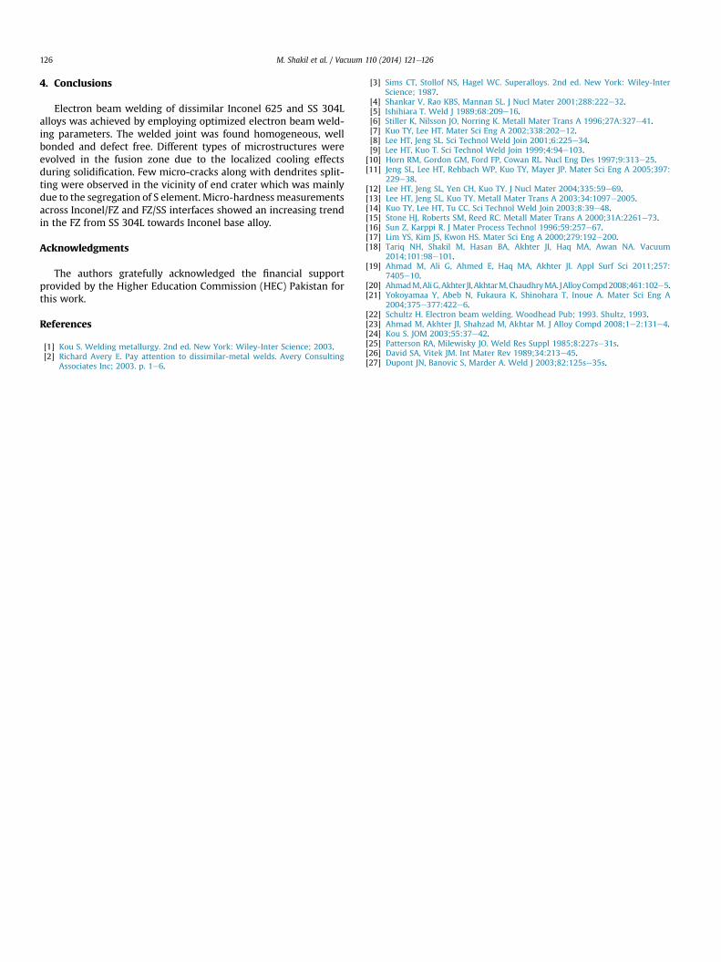
Fig. 8 shows the high magnification SEM micrograph of FZ area(marked by region-3 in Fig. 3) showing dendritic microstructurecomposed of two types namely, columnar dendrites and cellulardendrites. This microstructure is attributed to the different thermo-physical properties of Inconel 625 & SS 304L including thermalconductivity and specific heat which vary with temperature. Forinstance the thermal conductivities of Inconel 625 & SS 304L at
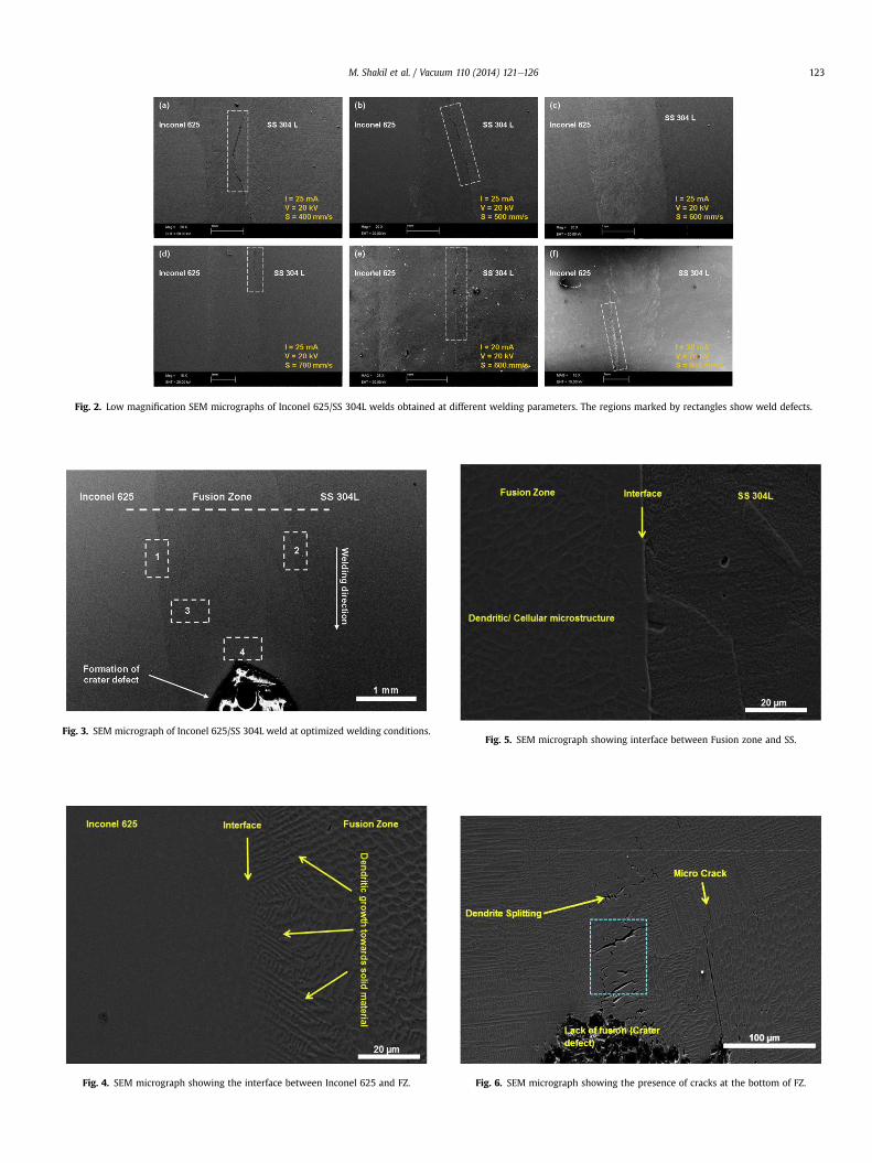
Fig. 2. Low magnification SEM micrographs of Inconel 625/SS 304L welds obtained at different welding parameters. The regions marked by rectangles show weld defects.
Fig. 3. SEM micrograph of Inconel 625/SS 304L weld at optimized welding conditions.
Fig. 4. SEM micrograph showing the interface between Inconel 625 and FZ.
Fig. 5. SEM micrograph showing interface between Fusion zone and SS.
Fig. 6. SEM micrograph showing the presence of cracks at the bottom of FZ.
M. Shakil et al. / Vacuum 110 (2014) 121e126 123
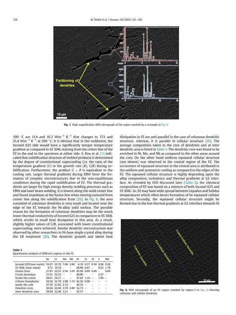
Fig. 7. High magnification SEM micrograph of the region marked by a rectangle in Fig. 6.
M. Shakil et al. / Vacuum 110 (2014) 121e126124
100 �C are 11.4 and 16.3 Wm�1 K�1 that changes to 17.5 and21.4 Wm�1 K�1 at 500 �C. It is obvious that in the weldment, theInconel 625 side would have a significantly steeper temperaturegradient as compared to SS 304L starting from the center line of theFZ to the end to the specimen at either side. S. Kou et al. [1] indi-cated that solidification structure of welded products is determinedby the degree of constitutional supercooling (i.e. the ratio of thetemperature gradient (G) to the growth rate (R), G/R) during so-lidification. Furthermore, the product G � R is equivalent to thecooling rate. Larger thermal gradients during EBW favor the for-mation of complex microstructures due to the non-equilibriumconditions during the rapid solidification of FZ. The thermal gra-dients are larger for high energy density welding processes such asEBWand laser beamwelding. It is lowest along the weld center lineand found maximum at the fusion line when moving outward fromcenter line along the solidification front [26]. In Fig. 8, the areaconsisted of columnar dendrites is very small and located near theedge of the FZ towards the Ni-alloy solid surface. The possiblereason for the formation of columnar dendrites may be the muchlower thermal conductivity of Inconel 625 in comparison to SS 304Lwhich results in small heat dissipation in this area. As a result,slightly higher values of G/R, associated with lower constitutionalsupercooling, were achieved. Similar dendritic microstructure wasobserved by other researchers in Ni-base single crystal alloy duringthe EB treatment [20]. The dendritic growth and latent heat
Table 3Quantitative analysis of different regions in the FZ.
Ni Cr Mo Nb Fe Si Al S Mn
Inconel 625(base metal) 59.97 22.76 7.96 2.86 4.18 0.37 0.36 0.28 0.20SS 304L (base metal) 9.72 19.32 e e 68.48 0.47 e 0.23 1.78Fusion Zone 27.83 22.55 2.50 1.03 43.98 0.88 0.49 e 0.89Cracks boundary 31.01 23.53 e e 40.00 e e 2.57 e
Inside the cracks 28.61 26.17 e e 41.62 1.19 e 1.89 e
Cellular boundaries 28.26 22.70 2.88 1.13 42.26 0.98 e e e
Inside the cells 27.59 21.82 2.15 e 46.35 e e e e
Dendrite cores 36.66 22.69 3.79 2.00 32.73 e e e e
Inter dendritic area 29.94 22.46 2.21 e 43.37 e e e e
dissipation in FZ are anti-parallel in the case of columnar dendriticstructure, whereas, it is parallel in cellular structure [20]. Theaverage composition taken in the core of dendrites and at interdendritic area is listed in Table 3. The dendritic core was found to beenriched in Ni, Mo, and Nb as compared to the other areas aroundthe core. On the other hand uniform equiaxed cellular structure(not shown) was observed in the central region of the FZ. Theoccurrence of equiaxed structure in the central area is attributed tothe uniform and symmetric cooling as compared to the edges of theFZ. The equiaxed cellular structure is highly depending upon thealloy composition, turbulence and thermal gradients at S/L inter-face. As revealed by EDS discussed later (Table 2), the chemicalcomposition of FZ was based on a mixture of both Inconel 625 andSS 304L. So, FZmay havewide spread between Liquidus and Solidustemperatures which often favors formation of he equiaxed cellularstructure. Secondly, the equiaxed cellular structure might beformed due to the low thermal gradients at S/L interface towards SS
Fig. 8. SEM micrograph of an FZ region (marked by region-3 in Fig. 3) showingcolumnar and cellular dendrites.

Fig. 9. EDX point analysis across FZ/Inconel and FZ/SS interfaces.
M. Shakil et al. / Vacuum 110 (2014) 121e126 125
304L side. In other words, much lower G/R ratio was achieved atcentral region.
It is again clear from Table 3 that the dendritic cells boundariesare enriched in Mo and Nb as compared to the inner areas ofcellular structures. Since Mo and Nb have large radii in comparisonto the other elements in the melt pool, they cause segregationduring the terminal solidification. It has been reported in theliterature that in Nb-bearing superalloys, the terminal solidificationis different due to the presence of Nb element which is a strongsegregant controlling terminal solidification reaction [27].
In order to determine compositional variation across Inconel/FZinterface, FZ and FZ/SS interface, EDS microanalysis (Fig. 9) wasperformed along thewhite dash line indicated in Fig 3. A significantvariation of Ni and Fe was observed across Inconel/FZ and FZ/SSinterfaces. The large variation of Ni and Fe in FZ was mainly due to
Fig. 10. XRD pattern of (a) Inconel 625 (b) SS 304L and (c) Fusion zone.
their fast diffusion in the melt pool, since Ni and Fe have smallatomic radii in comparison to other weld metal constituentelements.
3.2. X-ray diffraction
XRDpattern of Inconel 625, SS 304L, andwelded zone is shown inFig. 10. It was also revealed that the XRD pattern of Inconel alloy wasmuch similar with that of FZ. This indicates that both FZ and Inconelalloy have almost same crystal structure. However, EDS analysis(Table 2) revealed that the chemical compositionof FZwasbased on amixture of Inconel 625 and SS 304L. It can be clearly seen from Fig.10that the base Inconel 625 alloy as well as FZ show the presence of Ni(fcc) solid solution with lattice parameter of 360.58 pm and 360.60pm respectively. More or less same g-Ni matrix lattice parameter ofbase Inconel 625 alloy as well as FZ indicates that no intermetallicphases like g0, g00 or d were precipitated out in the matrix. Since thecooling rate during EBW is very high, most of the strengthening el-ements like Nb andMo remained in the solid solution of g-Ni matrixand formed no precipitates. It was also observed that XRD peaks in-tensity of FZ was decreased and slightly shifted towards the lowerangles which might be attributed to the residual stresses induced byfast coolingof FZ [20] and large variationofNi andFe content in the FZ(Table 3, Fig. 9).
3.3. Micro-hardness
The micro-hardness measurements were made by using Vickershardness tester. Fig. 11 shows the difference in hardness valuesbetween the Inconel 625, FZ, and SS 304L. Inconel 625 is a solutionstrengthened Ni-based superalloy with higher hardness values ascompared to the SS 304L. The approximate length of FZ was foundto be 2.4 mm. The hardness measured in the FZ showed overall anincreasing trend moving from SS 304L side towards the Inconelalloy.
The hardness in the weld increased from 150 to 225 HVN. Thismight be caused by alterations in the structure across the weldcross-section. However, within the FZ the hardness values werescattered that may be attributed to the convection effects in theweld metal as well as due to the variation of supersaturation of Nband Mo strengthening elements in the g-matrix.
Fig. 11. Microhardness profile across the FZ.
M. Shakil et al. / Vacuum 110 (2014) 121e126126
4. Conclusions
Electron beam welding of dissimilar Inconel 625 and SS 304Lalloys was achieved by employing optimized electron beam weld-ing parameters. The welded joint was found homogeneous, wellbonded and defect free. Different types of microstructures wereevolved in the fusion zone due to the localized cooling effectsduring solidification. Few micro-cracks along with dendrites split-ting were observed in the vicinity of end crater which was mainlydue to the segregation of S element. Micro-hardnessmeasurementsacross Inconel/FZ and FZ/SS interfaces showed an increasing trendin the FZ from SS 304L towards Inconel base alloy.
Acknowledgments
The authors gratefully acknowledged the financial supportprovided by the Higher Education Commission (HEC) Pakistan forthis work.
References
[1] Kou S. Welding metallurgy. 2nd ed. New York: Wiley-Inter Science; 2003.[2] Richard Avery E. Pay attention to dissimilar-metal welds. Avery Consulting
Associates Inc; 2003. p. 1e6.
[3] Sims CT, Stollof NS, Hagel WC. Superalloys. 2nd ed. New York: Wiley-InterScience; 1987.
[4] Shankar V, Rao KBS, Mannan SL. J Nucl Mater 2001;288:222e32.[5] Ishihiara T. Weld J 1989;68:209e16.[6] Stiller K, Nilsson JO, Norring K. Metall Mater Trans A 1996;27A:327e41.[7] Kuo TY, Lee HT. Mater Sci Eng A 2002;338:202e12.[8] Lee HT, Jeng SL. Sci Technol Weld Join 2001;6:225e34.[9] Lee HT, Kuo T. Sci Technol Weld Join 1999;4:94e103.
[10] Horn RM, Gordon GM, Ford FP, Cowan RL. Nucl Eng Des 1997;9:313e25.[11] Jeng SL, Lee HT, Rehbach WP, Kuo TY, Mayer JP. Mater Sci Eng A 2005;397:
229e38.[12] Lee HT, Jeng SL, Yen CH, Kuo TY. J Nucl Mater 2004;335:59e69.[13] Lee HT, Jeng SL, Kuo TY. Metall Mater Trans A 2003;34:1097e2005.[14] Kuo TY, Lee HT, Tu CC. Sci Technol Weld Join 2003;8:39e48.[15] Stone HJ, Roberts SM, Reed RC. Metall Mater Trans A 2000;31A:2261e73.[16] Sun Z, Karppi R. J Mater Process Technol 1996;59:257e67.[17] Lim YS, Kim JS, Kwon HS. Mater Sci Eng A 2000;279:192e200.[18] Tariq NH, Shakil M, Hasan BA, Akhter JI, Haq MA, Awan NA. Vacuum
2014;101:98e101.[19] Ahmad M, Ali G, Ahmed E, Haq MA, Akhter JI. Appl Surf Sci 2011;257:
7405e10.[20] AhmadM,AliG,Akhter JI,AkhtarM,ChaudhryMA. JAlloyCompd2008;461:102e5.[21] Yokoyamaa Y, Abeb N, Fukaura K, Shinohara T, Inoue A. Mater Sci Eng A
2004;375e377:422e6.[22] Schultz H. Electron beam welding. Woodhead Pub; 1993. Shultz, 1993.[23] Ahmad M, Akhter JI, Shahzad M, Akhtar M. J Alloy Compd 2008;1e2:131e4.[24] Kou S. JOM 2003;55:37e42.[25] Patterson RA, Milewisky JO. Weld Res Suppl 1985;8:227se31s.[26] David SA, Vitek JM. Int Mater Rev 1989;34:213e45.[27] Dupont JN, Banovic S, Marder A. Weld J 2003;82:125se35s.