microstructural imprints in failure of power plant boiler …
TRANSCRIPT
59 MS Proceedings of the 15th Int. AMME Conference, 29-31 May, 2012
15th International Conference on Applied Mechanics and Mechanical Engineering.
Military Technical College Kobry El-Kobbah,
Cairo, Egypt.
MICROSTRUCTURAL IMPRINTS IN FAILURE OF
POWER PLANT BOILER TUBES
U. K. Chatterjee*
ABSTRACT Power plant boiler tubes fail in service due to a number of reasons and through various mechanisms. Overheating is a prime cause, and creep, corrosion, erosion and hydrogen damage constitute major mechanisms of failure. Long-term overheating brings about microstructural changes like grain growth, disintegration of pearlite, spheroidization of carbides, graphitization and decarburization leading to loss of strength of the tube material, eventually resulting in stress rupturing or creep rupture through grain boundary void formation. A tube burst resulting from short-term overheating also often bears the imprint of microstructural changes occurring due to transformation of the high temperature phase. Overheating also accelerates the process of hydrogen damage, where the presence of grain boundary fissures bears the evidence of such type of failure. The paper deals with the theoretical aspects of microstructural changes as encountered in boiler tube failures and presents a few case histories to highlight the metallographic features in failures due to overheating and hydrogen damage. KEY WORDS Failure Analysis, Power Plant, Boiler Tubes, Microstructures. ---------------------------------------------------------------------------------------------------------------- * Metallurgical Consultant & Professor (Retired), Indian Institute of Technology,
Kharagpur 721302, India. E-mail: [email protected].
60 MS Proceedings of the 15th Int. AMME Conference, 29-31 May, 2012
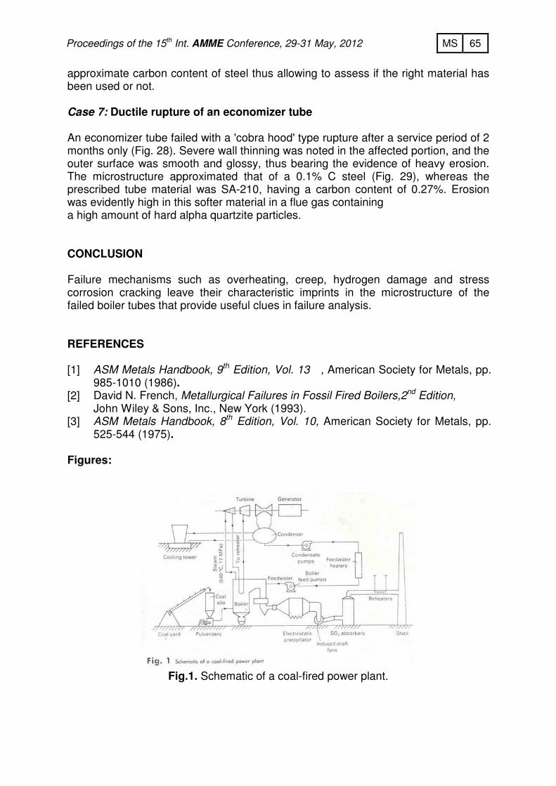
INTRODUCTION Thermal power generation occupies the major share in global power generation in which steam power plants play the leading role. Three fluid-flow loops viz. fuel-air, water-steam and condenser cooling, operate in a fossil-fired steam power plant (Fig.1) [1]. In the water-steam loop, clean feedwater is converted into superheated steam in a boiler, which expands through a series of turbines, converting its heat into mechanical energy, and is condensed, conditioned, pumped, and heated as feedwater. The boiling system comprises various units viz. waterwalls, superheaters, reheaters and economizers. The total length of tubes used in these units in a 210 MW plant measures nearly 120 km. About 40-50% of the unscheduled power plant shutdowns are due to boiler tube failure. All the units of the boiling system are affected and the failure is manifested in the form of bursting, cracking, slit or hole formation, and bulging or blistering, often in association with tube wall thinning. Short-term and long-term overheating, corrosion, erosion, hydrogen damage and fatigue are the major causes and mechanisms of failure. Use of defective material or a material not conforming to specifications and also weld defects are responsible in some cases. Failure analysis is carried out to identify the cause and establish the mechanism of failure with the aim of taking preventive measures against future occurrences. Several failure mechanisms involve a change in the microstructure from its original configuration. Identification of these microstructural imprints by metallographic and fractographic examination provides an useful means to establish the cause of failure in many instances. TUBE MATERIALS The service conditions of a coal-fired boiler are most severe. Flame temperatures may reach more than 1650 C during combustion of the fuel. Life expectancies of these steam generators are 25 to 30 years or more. Tube-metal temperatures within the furnace will be 400 C and up; in superheaters and reheaters, temperatures of 620 C are common. The materials used in the construction of boiler tubes are carbon steels (SA- 178A, SA- 210 etc), carbon + ½ Mo (SA- 209 T-1), 1 ¼ Cr- ½ Mo (SA-213 T-11), 2 ¼ Cr-1 Mo (SA 213 T-22) steels, and several grades of stainless steels (304, 321 H etc.). The oxidation limits, i.e. the temperatures at which wastage is excessive for safe service for 25-30 years, for these alloys are listed in Table 1. The waterwalls of sub-critical boilers are carbon steels, occasionally SA-209. Cr-Mo steels and stainless steels are used for superheaters and reheaters. Economizers are usually carbon steel, SA-210 or SA-178. However, the oxidation limits have no bearing on the failures associated with microstructural changes, though the microstructure is at times helpful in assessing whether or not the right material is used. In this paper, stainless steels will not be dealt with.

61 MS Proceedings of the 15th Int. AMME Conference, 29-31 May, 2012
Table 1. Oxidation limit of tube materials.
Material Temperature [ºC]
Carbon steel (SA210, SA106) 450
Carbon + ½ Mo (SA- 209 T-1) 480
1 ¼ Cr- ½ Mo (SA-213 T-11) 550
2 ¼ Cr-1 Mo (SA 213 T-22) 580
18 Cr- 8 Ni (304, 321, 347) 700
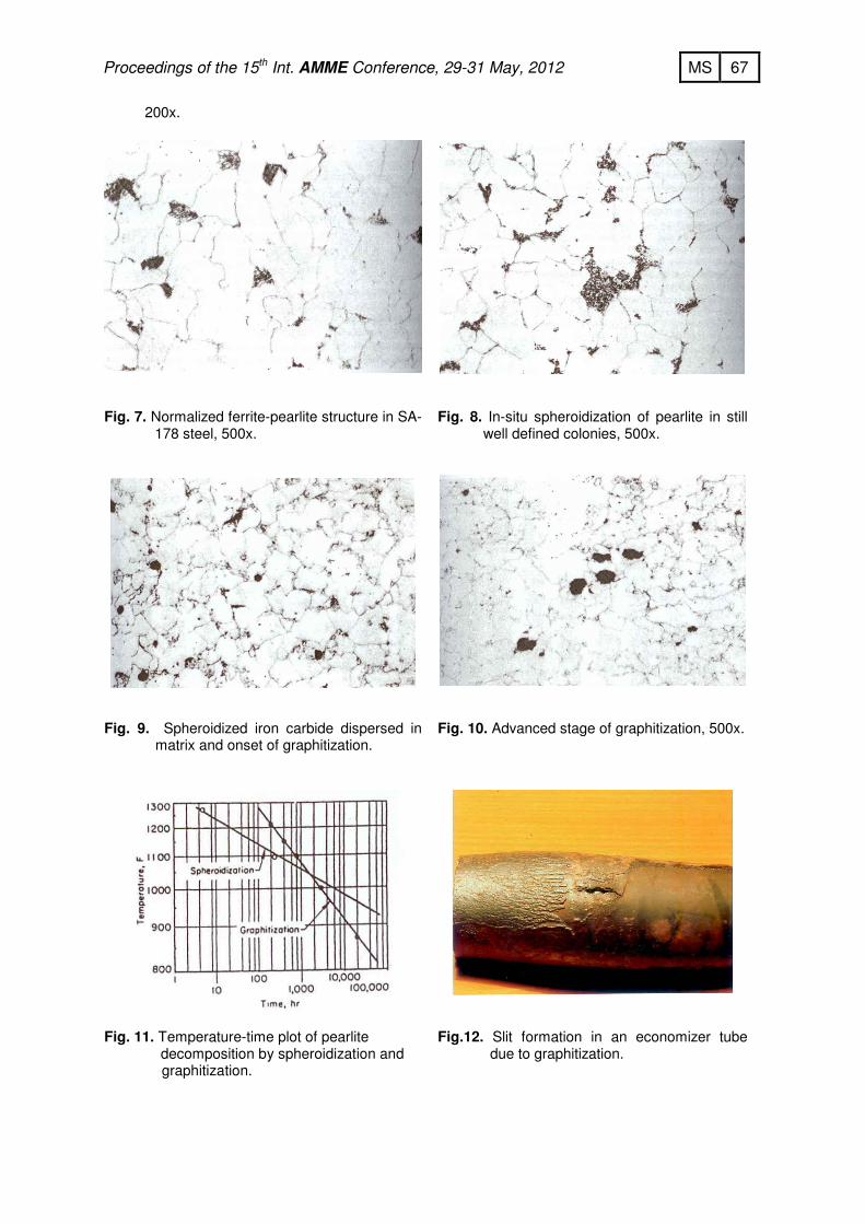
OVERHEATING According to a 25-year period analysis by a USA based firm , the mechanical failures constitute 81% of the total number of failures, and 19% are due to corrosion [2]. Again, nearly 80% of the mechanical failures have been the results of overheating. ASM Metals Handbook [3] reports of a 12-year period survey in which 201 failures out of a total 413 investigations, i.e. 48.7% have been found to be due to overheating. Overheating results from:1) Restriction of flow within a heated tube, that can be mild or severe, and 2) Localized hot spots in a tube wall. Overheating can be of two types:1) Rapid or short-term overheating, and 2) Prolonged or long-term overheating. A mild restriction of flow can result from: 1) Local imbalance of flow among tubes joined to a common header, 2) Localized deposits near a tube inlet, 3) Local variations in inside diameter because of variations in tube installation techniques. A severe restriction may be caused by: 1) Sudden loss or general loss in circulation (e.g. from feed pump failure), 2) Sudden local loss in circulation (e.g. due to leakage/rupture in adjacent tubes). Mild restrictions of flow favor a small degree of overheating and failure by stress rupture. A sudden or severe restriction favors rapid overheating and tensile rupture. Localized hot spots develop from: 1) Direct flame impingement, 2) Fuel ash deposits on outer surface, 3) Deposits on inner surface e.g. corrosion scale, hardness scale, and 4) Departure from nucleate boiling. The inner surface scale (ID scale) influences the heat transfer from the tube to the fluid. A tightly bound ID scale will have good heat transfer characteristics, while a scale separated from the steel having a gap will hinder heat transfer. Initial blistering or bulging of a tube due to material softening can cause such a separation, as exemplified in Fig. 2 [2]. The impeded heat transfer further raises the tube temperature leading to rupture. The thickness of the ID scale also dictates heat transfer and subsequent tube overheating, as shown in Fig. 3 [3]. The following case study exemplifies the microstructural imprint of short-term overheating:

62 MS Proceedings of the 15th Int. AMME Conference, 29-31 May, 2012
Case 1: Thin-lip rupture of a waterwall tube Fig. 4 shows the general view of a rupture with thin lips indicating a ductile fracture. The microstructure of the unaffected portion showed a normal ferritic-pearlitic structure (Fig. 5). The affected area showed martensitic structure (Fig. 6) bearing a testimony to overheating above AC1 temperature that softened the material leading to ductile fracture. Long-term heating brings about several changes in the microstructure depending on the temperature and time of heating. These include disintegration of pearlite, spheroidization of carbide, graphitization, grain growth, decarburization, grain boundary void formation and intergranular fissuring. PEARLITE DISINTEGRATION Figures 7 to 10 [2] demonstrate the expected changes in morphology in plain carbon and carbon-Mo steels from a normalized structure of ferrite and pearlite exhibited by an unused or new tube. The first stage in the transformation is an in situ breakdown of the pearlite; the shape of the pearlite colonies remaining intact, but the platelets of iron carbide become spheroids. The next stage is the disappearance of pearlite colonies and dispersion of spherical carbide particles throughout the matrix and, finally, the formation of graphite particles and their growth. The addition of chromium stabilizes the carbide so that even for very long times or high temperatures no graphite is formed. Spheroidization and graphitization are competing processes (Fig. 11) [3]. At low temperatures, graphitization occurs before the pearlite colonies have completely spheroidized and disappeared. At elevated temperatures, spheroidization occurs before graphitization. In both cases, temperatures of at least about 455 C for carbon steel and 470 C for carbon- ½ Mo steel are necessary to transform the iron carbide to graphite. Graphitization can occur before spheroidization, but complete spheroidization develops when there is sufficient time. Case 2: Slit formation in an economizer tube An economizer tube made of SA-192 developed a slit after a service life of 20 years (Fig. 12). The microstructure revealed intact colonies of disintegrated pearlite and graphite (Fig. 13), typical of graphitization at low temperatures. Case 3: Thick-lip rupture of a superheater tube Thick lip rupture was experienced in a superheater tube after prolonged service (Fig. 14). The microstructure showed complete spheroidization preceding graphitization (Fig. 15), typical of graphitization at higher temperatures.
DECARBURIZATION Decarburization takes place on the steam side of the tubes due to the reaction of steam and carbon to form carbon monoxide and hydrogen:
63 MS Proceedings of the 15th Int. AMME Conference, 29-31 May, 2012
H2O + C = H2 + CO Carbon diffuses from the interior of the metal to the surface where the reaction occurs, depleting the microstructure of carbon and leaving behind essentially pure ferrite. Mechanical strength of the material is reduced due to decarburization. Decarburization is illustrated in Fig. 16. Decarburization is observed also in hydrogen damage, the mechanism of which is discussed later. CREEP VOIDS AND FISSURES Creep is the permanent plastic deformation of metals at elevated temperatures and stresses much less than the high temperature yield stress. Creep is a time-dependent phenomenon. The deformation continues with time at a constant stress and in the final stage of creep deformation the component fails by stress-rupture that may take several ten thousand hours. The first sign of creep damage is the appearance of longitudinal cracks at the scale-metal interface. As the tube expands by creep deformation process, the brittle steam-side oxide cannot follow the expansion, and longitudinal cracks appear. Locally a cusp forms at the interface that acts as a stress raiser and the creep damage in the form of voids and fissures fan out from the cusp in the decarburized layer (Fig. 17) [2]. Inside the metal, creep damage first appear as tiny voids at triple points where the three grains come together that subsequently grow out as intergranular fissures, as illustrated in the following case study. Case 4: Slit formation in a reheater tube A reheater tube failed through a slit formation at a bend (Fig. 18). No decrease in wall thickness was noted. The microstructure revealed numerous IG fissures in the affected area (Fig. 19).Grain boundary voids were detected in the unaffected zone (Fig. 20), indicating the onset of creep damage. GRAIN GROWTH Grain growth takes place when the metal is heated at higher temperatures for sufficiently long time. With the input of thermal energy, the system attempts to lower the energy by reducing the grain boundary areas. The strength of the material decreases with increasing grain size, and consequently tensile, fatigue and creep failures are accelerated. Case 5: Thick-lip 'fish mouth' failure of a reheater tube The reheater tube showed a 'thick lip 'fish mouth' failure with some bulging at a bend (Fig. 21). The affected portion revealed excessive grain growth and numerous IG cracks (Fig. 22). The unit was reported to have been in operation for less than two

64 MS Proceedings of the 15th Int. AMME Conference, 29-31 May, 2012
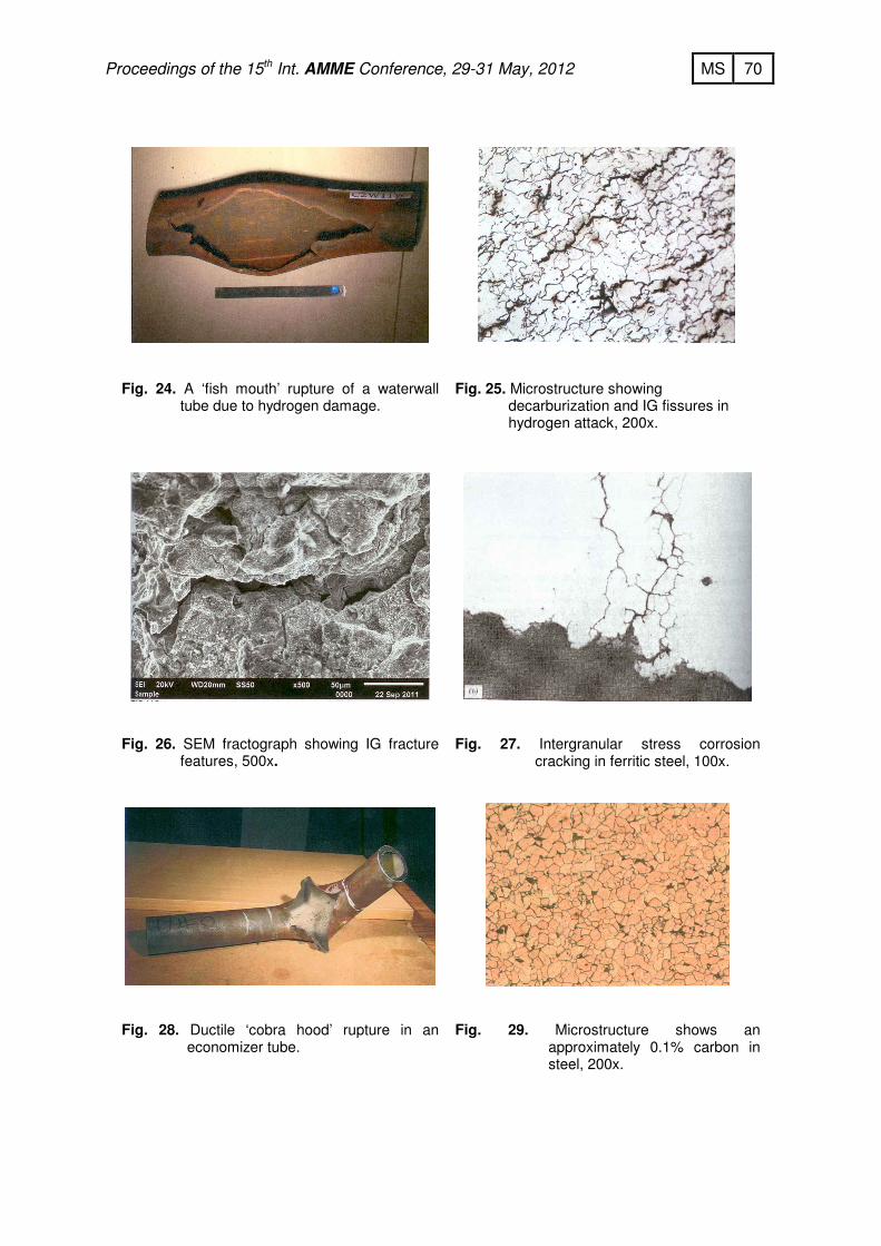
years, and a creep rupture was not normally expected. Some wall thinning due to erosion by unburnt coal particles was indicated that could have increased the hoop stress at the end. This, in association with decreased strength and intense continuous overheating, was inferred to have led to creep stress rupture. HYDROGEN DAMAGE Hydrogen damage occurs in high-pressure boilers, usually under heavy scale deposits, on the steam side of a boiler tube. The most frequent location is the highest-heat-release regions of the furnace, the area under the burner elevations. Hydrogen damage is usually caused by operation of the boiler with low -pH water chemistry [1]. For example, when seawater enters the boiler through a condenser leak, the pH will drop to the acid range. Under these conditions, the tube wall corrodes locally producing atomic hydrogen as corrosion product:
Fe + 2 HCl + Fe Cl2 + 2H
Atomic hydrogen diffuses into the steel and reacts with iron carbide to form methane:
4 H + Fe3C = CH4 + 3Fe
Methane gas collects at grain boundary sites, the pressure of which produces small discrete intergranular fissures that eventually link up to cause a through wall failure. Very often a 'window' type fracture occurs (Fig. 23). The microstructure of the damaged area displays decarburization and IG fissures. Case 6: Hydrogen damage of a waterwall tube A thick lip 27 cm x 11 cm wide 'fish mouth' type opening was experienced in a waterwall tube (Fig. 24). The microstructure showed decarburization and IG fissures (Fig. 25). SEM fractograph indicated intergranular failure features (Fig. 26). STRESS CORROSION CRACKING Stress corrosion cracking (SCC) is the failure of a metal stressed in tension below the yield point with simultaneous exposure to a specific corroding environment. Both intergranular and transgranular cracks with branching are observed. Carbon steels exhibit stress corrosion cracking, also known by the name caustic embrittlement, in concentrated hydroxide solutions. The cracking is intergranular in nature (Fig. 27) [2]. DEFECTIVE MATERIAL Microstructures reveal welding defects like incomplete fusion or an inclusion from where a fatigue fracture might have initiated. Since the amount of pearlite in the material increases with the carbon content, the microstucture indicates the
65 MS Proceedings of the 15th Int. AMME Conference, 29-31 May, 2012
approximate carbon content of steel thus allowing to assess if the right material has been used or not. Case 7: Ductile rupture of an economizer tube An economizer tube failed with a 'cobra hood' type rupture after a service period of 2 months only (Fig. 28). Severe wall thinning was noted in the affected portion, and the outer surface was smooth and glossy, thus bearing the evidence of heavy erosion. The microstructure approximated that of a 0.1% C steel (Fig. 29), whereas the prescribed tube material was SA-210, having a carbon content of 0.27%. Erosion was evidently high in this softer material in a flue gas containing a high amount of hard alpha quartzite particles. CONCLUSION Failure mechanisms such as overheating, creep, hydrogen damage and stress corrosion cracking leave their characteristic imprints in the microstructure of the failed boiler tubes that provide useful clues in failure analysis. REFERENCES [1] ASM Metals Handbook, 9th Edition, Vol. 13 , American Society for Metals, pp.
985-1010 (1986). [2] David N. French, Metallurgical Failures in Fossil Fired Boilers,2nd Edition,
John Wiley & Sons, Inc., New York (1993). [3] ASM Metals Handbook, 8th Edition, Vol. 10, American Society for Metals, pp.
525-544 (1975). Figures:
Fig.1. Schematic of a coal-fired power plant.

66 MS Proceedings of the 15th Int. AMME Conference, 29-31 May, 2012
Fig. 2(a). Tightly bound ID scale, 25x.
Fig. 2(b). ID scale separated from the steel leaving a gap of about 0.3 mil, 500x.
Fig. 3. Scale thickness versus tube temperature.
Fig. 4. Thin-lip ductile rupture of a waterwall tube.
Fig. 5. Microstructure of unaffected portion showing normal ferrite-pearlite structure,
Fig. 6. Microstructure of lip portion showing
martensite, 200x.
67 MS Proceedings of the 15th Int. AMME Conference, 29-31 May, 2012
200x.
Fig. 7. Normalized ferrite-pearlite structure in SA-
178 steel, 500x.
Fig. 8. In-situ spheroidization of pearlite in still
well defined colonies, 500x.
Fig. 9. Spheroidized iron carbide dispersed in
matrix and onset of graphitization.
Fig. 10. Advanced stage of graphitization, 500x.
Fig. 11. Temperature-time plot of pearlite decomposition by spheroidization and
graphitization.
Fig.12. Slit formation in an economizer tube
due to graphitization.
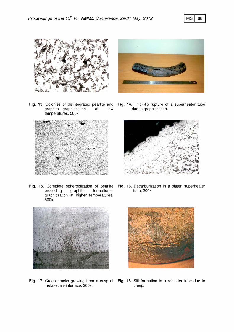
68 MS Proceedings of the 15th Int. AMME Conference, 29-31 May, 2012
Fig. 13. Colonies of disintegrated pearlite and
graphite—graphitization at low temperatures, 500x.
Fig. 14. Thick-lip rupture of a superheater tube
due to graphitization.
Fig. 15. Complete spheroidization of pearlite
preceding graphite formation—graphitization at higher temperatures, 500x.
Fig. 16. Decarburization in a platen superheater
tube, 200x.
Fig. 17. Creep cracks growing from a cusp at
metal-scale interface, 200x.
Fig. 18. Slit formation in a reheater tube due to
creep.

69 MS Proceedings of the 15th Int. AMME Conference, 29-31 May, 2012
Fig. 19. Creep deformation generated IG
fissures near fracture, 200x.
Fig. 20. Void formation at grain boundary triple
points due creep deformation away from fracture, 200x.
Fig. 21. ‘Fish mouth’ ruptures of a reheater
tube due to grain growth and creep deformation.
Fig. 22 (a). Normal ferrite-pearlite structure in
the unaffected portion, 200x.
Fig. 22 (b). Grain growth and IG cracks
revealed in the affected portion, 50x.
Fig. 23. A ‘window’ type rupture due to
hydrogen damage in a waterwall tube.
70 MS Proceedings of the 15th Int. AMME Conference, 29-31 May, 2012
Fig. 24. A ‘fish mouth’ rupture of a waterwall
tube due to hydrogen damage.
Fig. 25. Microstructure showing
decarburization and IG fissures in hydrogen attack, 200x.
Fig. 26. SEM fractograph showing IG fracture
features, 500x.
Fig. 27. Intergranular stress corrosion
cracking in ferritic steel, 100x.
Fig. 28. Ductile ‘cobra hood’ rupture in an
economizer tube.
Fig. 29. Microstructure shows an
approximately 0.1% carbon in steel, 200x.