microsoft word - l03_audjg_2007.pdf
TRANSCRIPT

7/28/2019 Microsoft Word - L03_AUDJG_2007.pdf
http://slidepdf.com/reader/full/microsoft-word-l03audjg2007pdf 1/5
THE ANNALS OF “DUNĂREA DE JOS” UNIVERSITY OF GALAłIFASCICLE V, TECHOLOLOGIES IN MACHINE BUILDING, ISSN 1221-4566
2007
15
Designing of a Reconfigurable Set of inverse Re-Drawing Dies
Aided by FEM SimulationC. Maier1, V. Tabacaru1, M. Banu1, S. Bouvier2, V. Marinescu1
1Universitatea “Dunărea de jos” GalaŃi, Facultatea de Mecanică2University Paris13, LPMTM – 93430 Villetaneuse, France
Abstract
This paper deals with the methodology for developing a laboratory inverse re-
drawing device. The drawing process is performed in two phases: a direct drawing
of a circular blank followed by a second reverse re-drawing phase on the same
device. Finite element simulations are carried out in order to i).define geometrical
characteristics of the modular re-drawing device and to ii). estimate the punch force evolution for different dimensions of punch, die and blankholder and for a
large class of materials. Based on such FEM simulations, springs for the developed
reverse deep drawing device are dimensioned. The use of springs gives the
possibility to deform the material with an imposed blank-holder force. Finally, a
draw of the designed modular device is presented considering all the results of the
finite element simulation..
Keywords: finite element simulations, inverse re-drawing, strain path, modular
device.
1. Introduction
The analysis of the inverse re-drawing process
provides severa l advantages as (i ) the imposedstrain path changes are severe and complexleading to a better analysis of the accuracy of the finite element analysis, (ii) large amount of deformation can be imposed where limitationsdue to the localization problems are reduced,(iii) the imposed strain path changes candetermine the compensation of the bending-unbending effects (tensile stress and bendingmoment) due to the material flow over the toolsradius during the first stage of t he deep-drawing
process.In this study we propose to proceed with
a direct drawing of a circular blank followed bya second inverse re-drawing stage using alaboratory device. These two stages must to be
progress ive in order to avoid the errors due tothe positioning of the piece obtained in the firststage.
2. Design of the inverse
re-drawing dies
The laboratory device is designed consideringthese cases:
- material – AL5182, DP600, HSLA (table1) ;- pieces type 1 and 2 (f ig .1, table 2) .
Table 1
Mater ia l Y 0 [Mpa]
R m [Mpa]
E[Mpa]
ν
AL5182 130 340 72000 0 .32
DP600 260 840 210000 0 .33
HSLA 370 530 210000 0.33
Table 2
Typeof the piece
D[mm]
T[mm]
H[mm]
R [mm]
78 1 70 8,51 74 1 ,2 70 10
70 1 ,5 70 112 60 1 70 8 ,5
52 1 ,2 77 10
This device has changeable tools (punch,
die, blankholder) in order to assure theconditions to obtain all pieces, using allmaterials considered.

7/28/2019 Microsoft Word - L03_AUDJG_2007.pdf
http://slidepdf.com/reader/full/microsoft-word-l03audjg2007pdf 2/5
FASCICLE V THE ANNALS OF ‘DUNĂREA DE JOS” UNIVERSITY OF GALAłI
Figure 1.
The definition of the tool-sets (punch,die, blankholder, clearence) and choice of
process parameters (number of forming stages ,forces to apply) must be performed for everytype of the piece and material co nsidered.
Improvement of design and tryout procedures using numerica l simulation mayhave a significant impact on the cost of thetools and on the reduction of the total time fromdesign to manufacture, also with the possibilityto provide better solution than those determinedfrom purely experimental tryout procedures.
Following the preliminary design, thetools must have the geometry presented infigure 2 in order to perform t he deep-drawing intwo stages on the same device.
Figure 2
3. Finite element simulation
Finite element simulations using a static-explicit finite element code STAMP3D,released within Integrated V-CAD ResearchSystem Program in RIKEN Institute, Japan, and
an implicit code MARC Mentat 3.2 are carriedout in order to estimate the punch forceevolution for different dimensions of punch, dieand blankholder, and for a large class of materials.
We considered the symmetry of thesystem and its result, in order to model onlyhalf of it (figure 3).
Figure 3 . Equ ivalent p last ic s tra in
dis tr ibut ion during the second s tage .
The type of the f in i te e lement used i s plane s tress quadrat ic (4 nodes) e lement inMARC Mentat 3 .2 Hardening lawconsidered i s Swif t ( i so t ropic hardenind)for s teels (DP600 and HSLA) and Voce( iso t ropic hardening) for a luminium al loy .
Table 3 . Swif t law ( iso tropic hardening) parameters [1] .
Parameter DP600 HSLA
0Y 308.3 367.7
0ε 0 .00082 0.07157
n 0 .132 0.139
C 720.2 530.9
Table 4 . Voce law wi th k inemat ic
hardening parameters [1] Parameter Value
0Y 148 .5
RC 9 .7
sat R 192 .4
The s imulat ion wi th the in i t ia l parameter s has two problems: f ir s t ly the
simulat ion doesn’ t reach the end andundulat ions appear .
7/28/2019 Microsoft Word - L03_AUDJG_2007.pdf
http://slidepdf.com/reader/full/microsoft-word-l03audjg2007pdf 3/5
THE ANNALS OF ‘DUNĂREA DE JOS” UNIVERSITY OF GALAłI FASCICLE V
General ly when the s imulat iondoesn’ t reach the end i t ’s due to the nodes
posi t ions when they enter in contact , or fas t s t ress increases a t an increment of thesimulat ion .
These problems could be so lved by
some geometr ical modif icat ions , o r punchspeed modif icat ion .The parameters are modif ied one by
one in order to keep revers ib i l i ty i f thesimulat ion doesn’ t wel l run .
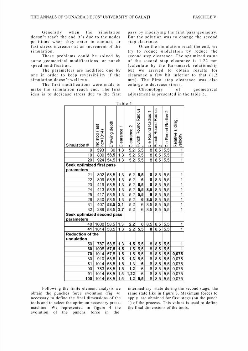
The f i rs t modif icat ions were made tomake the s imulat ion reach end . The f i rs tidea i s to decrease s t ress due to the f i rs t
pass by modifying the f irs t pass geometry.But the so lu t ion was to change the secondstep clearance.
Once the s imulat ion reach the end , wetry to reduce undulat ion by reduce thesecond s tep clearance. The opt imized value
of the second s tep clearance i s 1 ,22 mm(calcu late by the Kaszmarek relat ionship but we arr ived to obtain resu lts for c learance a few b i t in fer ior to that (1 ,2mm). The Fi rs t s tep clearance was alsoenlarge to decrease s t ress .
Chronology of geometr icalad justment i s p resented in the tab le 5 .
Table 5
Simulation # I n c s t o p ( l a s t
i n c = 1 0 1 4 )
D r a w i n g d e p t h
C l e a r a n c e 1
C l e a r a n c e 2
P u n c h R o u n d
R a d i u s
1 D i e R o u n d R a
d i u s 1
P u n c h R o u n d
R a d i u s
2 D i e R o u n d R a
d i u s 2
R e l a t i v e s l i d i n
g
v e l o c i t y
0 593 30 1,3 5,2 5,5 8 8,5 5,5 1
10 809 58,5 1,3 5,2 5,5 8 8,5 5,5 1
20 924 54,5 1,3 5,2 5,5 8 8,5 5,5 1
Seek optimized first passparameters
21 802 58,5 1,3 5,2 5,5 8 8,5 5,5 1
22 809 58,5 1,3 5,2 6 8 8,5 5,5 1
23 419 58,5 1,3 5,2 6,5 8 8,5 5,5 124 413 58,5 1,3 5,2 5,5 8,5 8,5 5,5 1
25 417 58,5 1,3 5,2 5,5 9 8,5 5,5 1
26 840 58,5 1,3 5,2 6 8,5 8,5 5,5 1
31 407 58,5 2,1 5,2 6 8,5 8,5 5,5 1
32 289 58,5 3,7 5,2 6 8,5 8,5 5,5 1
Seek optimized second passparameters
40 1000 58,5 1,3 2,2 6 8,5 8,5 5,5 1
41 1014 58,5 1,3 2,2 5,5 8 8,5 5,5 1
Reduction of theundulation
50 787 58,5 1,31,5
5,5 8 8,5 5,5 160 1005 57,5 1,5 1,5 5,5 8 8,5 5,5 1
70 1014 57,5 1,5 1,5 5,5 8 8,5 5,5 0,075
80 910 58,5 1,5 1,3 5,5 8 8,5 5,5 0,075
81 1014 58,5 1,5 1,3 6 8 8,5 5,5 0,075
90 783 58,5 1,5 1,2 6 8 8,5 5,5 0,075
91 1014 58,5 1,5 1,22 6 8 8,5 5,5 0,075
100 1014 58,5 1,5 1,2 5,5 8 8,5 5,5 0,075
Following the finite element analysis weobtain the punches force evolution (fig. 4)necessary to define the final dimensions of thetools and to select the optimum necessary press-
machine. We represented in figure 4 theevolution of the punchs force in the
intermediary state during the second stage, thesame state like in figure 3. Maximum forces toapply are obtained for first stage (on the punch1) of the process. This values is used to define
the final dimensions of the tools.

7/28/2019 Microsoft Word - L03_AUDJG_2007.pdf
http://slidepdf.com/reader/full/microsoft-word-l03audjg2007pdf 4/5
FASCICLE V THE ANNALS OF ‘DUNĂREA DE JOS” UNIVERSITY OF GALAłI
Figure 3 . Punch 1 and punch 3 force
evolution
DP600 Punch diameter 82.3 mm
0
20
40
60
80
100
120
0 10 20 30 40 50
Punch stroke [mm]
P u n c
h
f o r c e
[ k N
]
F igure 4 . Punch 1 force evolu t ion for
DP600 .
On the figure 5 we can notice the earingeffect due to the anisotropy (fig. 6) of thematerial and we use this one in order to check the height of the piece obtained in the firststage of the process.
Figure 5 . Earing ef fect for DP600 at 50
mm height obta ined a f ter the f i rs t s tage
0 10 20 30 40 50 60 70 80 900
0.2
0.4
0.6
0.8
1
1.2
DP600 (1.0 mm) : Variation of Hill's coefficient of anisotropyDP600 (1.0 mm) : Variation of Hill's coefficient of anisotropyDP600 (1.0 mm) : Variation of Hill's coefficient of anisotropyDP600 (1.0 mm) : Variation of Hill's coefficient of anisotropy
Orientation of the tensile axis with respect to RD, in degree sOrientation of the tensile axis with respect to RD, in degree sOrientation of the tensile axis with respect to RD, in degree sOrientation of the tensile axis with respect to RD, in degree s
C o e f f i c i e n t o f a n i s o t r o p y r
C o e f f i c i e n t o f a n i s o t r o p y r
C o e f f i c i e n t o f a n i s o t r o p y r
C o e f f i c i e n t o f a n i s o t r o p y r
Experimental valuesTheoretical values
F igure 6 . Anisotropy o f DP600
4. Conclusions
For the reverse re-drawing simulation thegeometry of the dies is defined. The DP600 andHSLA steel have the abilities to support the
severity of reverse re-drawing process. In thesame time theses steels are designed for thiskind of operation. The evaluate draw ratio (β2lim =1,75 ) on the second pass is very good(superior to the draw ratio on the first pass).
5. Acknowledgements
This work has been material and logisticfunded by the National Excellence ResearchProject -CEEX contract no. 22/2005.
References
1. . M. Banu, C. Maier, S. Bouvier, H. Haddadi, C.
Teodosiu Data Preprocessing and Identification of the Elastoplastic Constitutive Models - WP3, Task 1, 18-MonthsProgress Report, Digital Die Design Systems (3DS) IMS 199000051, (2001), 22-29.
2. R. E. Dick, J. W. Yoon, F. Barlat, Convolute Cut-Edge
Design for an Earless Cup in cup Drawing, In: NUMISHEET
2005, Eds. L.M. smith, F. Pourbograth, J.W Yoon, T.B. Stoughton,(2005), 713-718.
3. A. Baptista, J. L. Alves, M. Oliveira, D.M.
Rodrigues, L. F. Menezes, Application of the Incremental Volumetric Remapping Method in the Simulation of Multi-Step
Deep Drawing Processes, In: NUMISHEET 2005, Eds. L.M.smith, F. Pourbograth, J.W Yoon, T.B. Stoughton, (2005), 173-178

7/28/2019 Microsoft Word - L03_AUDJG_2007.pdf
http://slidepdf.com/reader/full/microsoft-word-l03audjg2007pdf 5/5
THE ANNALS OF ‘DUNĂREA DE JOS” UNIVERSITY OF GALAłI FASCICLE V
Proiectarea unui echipament tehnologic reconfigurabil
pentru ambutisarea inversa, utilizand simularea cu EF
Rezumat:
Aceasta lucrare are ca obiectiv dezvoltarea metodologiei de proiectare a unui
echipament tehnologic de laborator pentru ambutisare inversa, avand elemente
active schimbabile. Procesul de deformare se realizeaza in 2 etape: ambutisarea
directa a unui semifabricat plan de forma circulara, urmata de a doua ambutisare
pe acelasi echipament, in sens invers sensului de deplasare a materialului de la
prima ambutisare. Simularea cu elemente finite s-a realizat cu scopul: i). definiriicaracteristicilor dimensionale ale echipamentului modular si ii). estimarii evolutiei
fortei de deformare pentru diferite dimensiuni ale poansonului, placii active si placii
de retinere, pentru o gama larga de materiale. In final, echipamentul tehnologic de
laborator este dimensionat pe baza rezultatelor simularilor numerice.
Conception d’un équipement de laboratoirepour l’emboutissage inverse, en utilisant la simulation EF
Résume:
Ce papier a comme objectif le développement de la méthode de conception
d’un équipement de laboratoire pour l’emboutissage inverse, ayant le couple
poinçon - matrice changeable. Le processus de mise en forme se déroule pendant
deux étapes : l’emboutissage directe d’un ébauche plan de forme circulaire, suite
par le deuxième emboutissage réalisé sur le même équipement, dans le sens inverse
de déplacement du matériau que le premier emboutissage. La simulation EF a été
réalisée au but de : i). définir les characteristiques dimensionales des différents
modules de l’équipement ; ii). évaluation de l’évolution de la force du poinçon pour
différents dimensions des modules de l’équipement et différents matériaux del’ébauche. A la fin, la conception de l’équipement de laboratoire est faite à base des
résultats de la simulation numérique