microsoft windows 2000 ipsec guide
TRANSCRIPT

UNCLASSIFIED
i
UNCLASSIFIED
Report Number: C4-045R-01
Microsoft Windows 2000 IPsec Guide
Network Attack Techniques Division of the
Systems and Network Attack Center (SNAC)
National Security Agency 9800 Savage Rd. Suite 6704 Ft. Meade, MD 20755-6704
410-854-6015
Authors: Kim Downin Steven LaFountain
Updated: August 13, 2001Version 1.0

UNCLASSIFIED
UNCLASSIFIED ii
This Page Intentionally Left Blank

UNCLASSIFIED
UNCLASSIFIED iii
Warnings
Do not attempt to implement any of the settings in this guide without first testing in a non-operational environment.
This document is only a guide containing recommended security settings. It is not meant to replace well-structured policy or sound judgment. Furthermore this guide does not address site-specific configuration issues. Care must be taken when implementing this guide to address local operational and policy concerns.
The security changes described in this document only apply to Microsoft Windows 2000 systems and should not be applied to any other Windows versions or operating systems.
SOFTWARE IS PROVIDED "AS IS" AND ANY EXPRESS OR IMPLIED WARRANTIES, INCLUDING, BUT NOT LIMITED TO, THE IMPLIED WARRANTIES OF MERCHANTABILITY AND FITNESS FOR A PARTICULAR PURPOSE ARE EXPRESSLY DISCLAIMED. IN NO EVENT SHALL THE CONTRIBUTORS BE LIABLE FOR ANY DIRECT, INDIRECT, INCIDENTAL, SPECIAL, EXEMPLARY, OR CONSEQUENTIAL DAMAGES (INCLUDING, BUT NOT LIMITED TO, PROCUREMENT OF SUBSTITUTE GOODS OR SERVICES; LOSS OF USE, DATA, OR PROFITS; OR BUSINESS INTERRUPTION) HOWEVER CAUSED AND ON ANY THEORY OF LIABILITY, WHETHER IN CONTRACT, STRICT LIABILITY, OR TORT (INCLUDING NEGLIGENCE OR OTHERWISE) ARISING IN ANY WAY OUT OF THE USE OF THIS SOFTWARE, EVEN IF ADVISED OF THE POSSIBILITY OF SUCH DAMAGE.
This document is current as of August 13, 2001. See Microsoft's web page for the latest changes or modifications to the Windows 2000 operating system.

UNCLASSIFIED
UNCLASSIFIED iv
This Page Intentionally Left Blank

UNCLASSIFIED
UNCLASSIFIED v
Acknowledgements
The authors would like to acknowledge William Dixon of Microsoft Corporation for his help in understanding the implementation of IPsec in Windows 2000.

UNCLASSIFIED
UNCLASSIFIED vi
Trademark Information
Microsoft, MS-DOS, Windows, Windows 2000, Windows NT, Windows 98, Windows 95, Windows for Workgroups, and Windows 3.1 are either registered trademarks or trademarks of Microsoft Corporation in the U.S.A. and other countries.
All other names are registered trademarks or trademarks of their respective companies.

UNCLASSIFIED
UNCLASSIFIED vii
Table of Contents
Acknowledgements.....................................................................................................................................v Trademark Information ..............................................................................................................................vi Table of Contents ......................................................................................................................................vii Table of Figures..........................................................................................................................................ix Introduction..................................................................................................................................................1
Getting the Most from this Guide ............................................................................................................ 1 About the Microsoft Windows 2000 IPsec Guide.................................................................................... 2
Chapter 1 What is IPsec?............................................................................................................................3 IPsec Protocols ...................................................................................................................................... 3 IPsec Security Services.......................................................................................................................... 5 IPsec Modes of Use ............................................................................................................................... 8 Example Uses of IPsec .......................................................................................................................... 8
Chapter 2 IPsec in Windows 2000............................................................................................................13 IPsec Policy.......................................................................................................................................... 13
Creating IPsec Policies.................................................................................................................. 13 General IPsec Settings .................................................................................................................. 14 IPsec Policy Rules ......................................................................................................................... 14 Assigning and Using IPsec Policy.................................................................................................. 15 Creating and Storing IPsec Policy.................................................................................................. 15 Determining Effective Policy .......................................................................................................... 16 Implementing IPsec Policy............................................................................................................. 16 IPsec Policy Propagation ............................................................................................................... 17 Deleting IPsec Policy ..................................................................................................................... 18
Chapter 3 Designing an IPsec Architecture in Windows 2000 .............................................................19 Choosing an Architecture............................................................................................................... 19 Types of Data to Protect ................................................................................................................ 19 Which Machines Should Be Protected........................................................................................... 19 What Type of Protection is Needed? ............................................................................................. 19 What IPsec Mode Needed ............................................................................................................. 20 Setting up the IPsec Policy ............................................................................................................ 20
Chapter 4 Configuring IPsec Policy for Secure Workstation Communications .................................21 Creating New IPsec Policy............................................................................................................. 21 Setting up the IPsec Policy ............................................................................................................ 21
Chapter 5 Configuring IPsec Policy for Secure Domain Controller Communications.......................59 Setting up the IPsec Policy ............................................................................................................ 59
Appendix A IPsec Tools, Utilities, and Logs ..........................................................................................89 Appendix B Further Information ..............................................................................................................91 Appendix C References ............................................................................................................................93

UNCLASSIFIED
UNCLASSIFIED viii
This Page Intentionally Left Blank

UNCLASSIFIED
UNCLASSIFIED ix
Table of Figures
Figure 1 – Authentication Header Protocol...........................................................................................4 Figure 2 – Encapsulating Security Payload Protocol............................................................................4 Figure 3 – ESP, transport mode...........................................................................................................6 Figure 4 – ESP, tunnel mode ...............................................................................................................6 Figure 5 – Traffic Flow Security Via Tunnel Mode ESP........................................................................7 Figure 6 – Secure Communication Within an Enclave Using IPsec......................................................9 Figure 7 – Secure Communication Between Any Two Points Using IPsec ..........................................9 Figure 8 – Enclave-to-enclave Security Using IPsec..........................................................................10 Figure 9 – Remote-host to Enclave Security Using IPsec ..................................................................11 Figure 10 – Starting the Management Console..................................................................................22 Figure 11 – Selecting Add/Remove Snap-in ......................................................................................22 Figure 12 – Viewing the Available Snap-ins .......................................................................................23 Figure 13 – Selecting the IP Security Policy Management.................................................................23 Figure 14 – Selecting Which Computer the Snap-in will Manage.......................................................24 Figure 15 – Resulting Management Console .....................................................................................24 Figure 16 – Creating an IP Security Policy.........................................................................................25 Figure 17 - IPsec Security Policy Wizard ...........................................................................................25 Figure 18 – Activating the Default Response Rule .............................................................................26 Figure 19 – Setting the Initial Authentication Method .........................................................................26 Figure 20 - Setting General Policy Properties ....................................................................................27 Figure 21 – Setting the Methods to Protect the Exchange of Keys ....................................................28 Figure 22 – Further Configuration of Key Exchange Security Methods ..............................................28 Figure 23 – Adding a New IP Security Rule .......................................................................................29 Figure 24 – Specifying the Tunnel Endpoint.......................................................................................29 Figure 25 – Selecting the Network Type ............................................................................................30 Figure 26 – Selecting the Authentication Method...............................................................................30 Figure 27 – Adding IP Filter List .........................................................................................................31 Figure 28 – Naming the IP Filter List..................................................................................................31 Figure 29 – Selecting the Source Address of the IP Traffic ................................................................32 Figure 30 - Selecting the Destination Address of the IP Traffic ..........................................................32 Figure 31 – Selecting the Protocol Type ............................................................................................33 Figure 32 - Verifying that "Mirrored" is Selected.................................................................................33 Figure 33 - Selecting the New Filter List.............................................................................................34 Figure 34 -- Setting the Filter Action Behavior....................................................................................34 Figure 35 - IP Security Policies on Active Directory Window After New Policy Creation ....................35 Figure 36 – The Group Policy Snap-In...............................................................................................36 Figure 37 – Selecting the Group Policy Object...................................................................................36 Figure 38 - The Default Domain Controllers Group Policy Window....................................................37 Figure 39 - Default Domain Controllers Group Policy with IPsec Policy Assigned .............................37 Figure 40 – IP Security Policy Wizard ................................................................................................38 Figure 41 – Activating the Default Response Rule .............................................................................38 Figure 42 – Setting the Initial Authentication Method .........................................................................39 Figure 43 – Setting the Methods to Protect the Exchange of Keys ....................................................40 Figure 44 – Further Configuration of Key Exchange Security Methods ..............................................40 Figure 45 – Adding IP Filter List .........................................................................................................41 Figure 46 – Creating a New Filter Within the Filter List ......................................................................42 Figure 47 – Selecting the Source Address of the IP Traffic ................................................................42 Figure 48 – Selecting the Specific Destination Address for the IP Traffic...........................................43 Figure 49 – Selecting the Protocol Type ............................................................................................43 Figure 50 – Verifying that the Mirrored Option Box is Selected ..........................................................44 Figure 51 – Confirming the Filter is Set Correctly...............................................................................44 Figure 52 – Example of Repeated Procedure ....................................................................................45

UNCLASSIFIED
UNCLASSIFIED x
Figure 53 - Selecting the New Filter List.............................................................................................45 Figure 54 - Creating A Second Rule ..................................................................................................46 Figure 55 - Creating a Second Filter ..................................................................................................46 Figure 56 – Adding a New Action.......................................................................................................47 Figure 57 – Naming and Describing the New Action ..........................................................................48 Figure 58 -- Setting the Filter Action Behavior....................................................................................48 Figure 59 – Ensuring no Communication with Computers that don’t support IPsec ...........................49 Figure 60 – Specifying Security Level ................................................................................................49 Figure 61 - Customizing Security Level..............................................................................................50 Figure 62 – Selecting the New Filter Action .......................................................................................51 Figure 63 – Ensuring the New and Default Filter Lists are Selected...................................................51 Figure 64 – The Management Console..............................................................................................52 Figure 65 – The Group Policy Snap-In...............................................................................................52 Figure 66 – Selecting the Group Policy Object...................................................................................53 Figure 67 – Selecting the Default Domain Policy ...............................................................................53 Figure 68 – Closing the Add/Remove Snap-In Window .....................................................................54 Figure 69 – IP Security Policies on Active Directory...........................................................................54 Figure 70 – Highlighting the New IPsec Policy...................................................................................55 Figure 71 – Assigning the New IPsec Policy ......................................................................................55 Figure 72 – Confirming the Policy has been Assigned .......................................................................56 Figure 73 – Starting the Management Console..................................................................................60 Figure 74 – Selecting Add/Remove Snap-in ......................................................................................60 Figure 75 – Viewing Available Snap-Ins.............................................................................................61 Figure 76 – Selecting IP Security Policy Management.......................................................................61 Figure 77 – Selecting Which Computer the Snap-in will Manage.......................................................62 Figure 78 – Resulting Management Console .....................................................................................62 Figure 79 – Creating an IP Security Policy.........................................................................................63 Figure 80 – Naming and Describing the New Security Policy.............................................................63 Figure 81 – Activating the Default Response Rule .............................................................................64 Figure 82 – Setting the Initial Authentication Method .........................................................................64 Figure 83 – Setting the Configuration for Key Exchange....................................................................65 Figure 84 – Setting the Methods to Protect the Exchange of Keys ....................................................66 Figure 85 – Further Configuration of Key Exchange Security Methods ..............................................66 Figure 86 – Specifying the Tunnel Endpoint.......................................................................................67 Figure 87 – Selecting the Network Type ............................................................................................67 Figure 88 – Selecting the Authentication Method...............................................................................68 Figure 89 – Adding IP Filter List .........................................................................................................68 Figure 90 – Naming and Adding the New Filter..................................................................................69 Figure 91 – Selecting the Source Address for the IP Traffic...............................................................69 Figure 92 – Selecting the Specific Destination Address for the IP Traffic...........................................70 Figure 93 – Selecting a Protocol Type ...............................................................................................70 Figure 94 – Verifying that the Mirrored Option is Selected .................................................................71 Figure 95 – Confirming the Filter is Set Correctly...............................................................................71 Figure 96 – Example of Repeated Procedure ....................................................................................72 Figure 97 – Reviewing the New Filter List ..........................................................................................72 Figure 98 – Adding a New Action.......................................................................................................73 Figure 99 – Naming and Describing the New Action ..........................................................................73 Figure 100 – Setting the Filter Action Behavior ..................................................................................74 Figure 101 – Ensuring Continued Communication.............................................................................74 Figure 102 – Specifying Security Level ..............................................................................................75 Figure 103 – Customizing Security Level ...........................................................................................75 Figure 104 – Further Configuration of Security Methods....................................................................76 Figure 105 – Selecting the Filter Action for the Security Rule ............................................................76 Figure 106 – Ensuring the Filter List and Action are Selected............................................................77 Figure 107 – Ensuring the New and Default Filter Lists are Selected.................................................77 Figure 108 – The Management Console............................................................................................78

UNCLASSIFIED
UNCLASSIFIED xi
Figure 109 – The Group Policy Snap-In.............................................................................................78 Figure 110 – Selecting the Group Policy Object.................................................................................79 Figure 111 – Closing the Add/Remove Snap-in Window....................................................................80 Figure 112 – Resulting Management Console Window......................................................................80 Figure 113 – IP Security Policies on Active Directory.........................................................................81 Figure 114 – Highlighting the New IPsec Policy.................................................................................82 Figure 115 – Confirming the Policy has been Assigned .....................................................................83 Figure 116 – Saving and Naming the Console...................................................................................83 Figure 117 – Selecting IP Security Policies on Active Directory .........................................................84 Figure 118 – Selecting the Domain Controllers IPsec Policy..............................................................85 Figure 119 – Selecting the Domain Controllers Filter List ..................................................................85 Figure 120 – Modifying Action Properties...........................................................................................86 Figure 121 – Not Allowing Unsecured Communication ......................................................................86 Figure 122 -- Appendix A: IP Security Monitor ...................................................................................89

UNCLASSIFIED
UNCLASSIFIED xii
This Page Intentionally Left Blank

UNCLASSIFIED
UNCLASSIFIED 1
Introduction
Introduction The purpose of this guide is to inform the reader about Internet Protocol security (IPsec) services that are available in Microsoft Windows 2000 and how to configure these services to implement the desired network security policy. This guide does not attempt to provide individual IPsec security settings for all possible network architectures. Instead, this guide is designed to provide the reader an overview of the functionality that is available via IPsec and how it is implemented in Windows 2000, to provide a couple of worked examples, to make recommendations on critical security parameters, and to provide the reader with sufficient understanding to apply this information as necessary to their specific network architecture.
The Microsoft Windows 2000 IPsec Guide presents an introduction to IPsec protocols and services and an overview of how they are implemented in Windows 2000. Worked examples are used to illustrate the recommended IPsec configuration in a secure Windows 2000 network.
The authors intend this guide to be used as a reference to help the planning/design phase of a network development or upgrade process. This guide focuses on a single issue related to network security (i.e., IPsec) and it should not be used on its own as an all-encompassing network design guide. Rather, other reference materials, including other NSA –produced configuration guides, should also be used.
NOTE: This guide does not address specific security issues for the secure configuration of the Microsoft Windows 2000 operating system or any other network operating systems or services that may be mentioned.
This document is intended for Microsoft Windows 2000 network administrators and network designers. However, it should be useful for anyone involved with designing or maintaining a network that includes Microsoft Windows 2000 hosts and/or servers.
Getting the Most from this Guide
The following list contains suggestions for successfully using the Microsoft Windows 2000 IPsec Guide:
Read the guide in its entirety. Subsequent sections can build on information and recommendations discussed in prior sections.
If applicable, compare the recommendations in this guide to the existing network architecture.
Use a reasonable man theory when planning what a network needs:
o Implementing network devices without properly configuring them could lead to a more vulnerable network.
o Improper configuration of IPsec could prevent network communications.
o Network planning should include the necessary personnel to configure, manage and monitor all the devices and hosts on the network.
Windows 2000 system administrators should update with each service pack as

UNCLASSIFIED
UNCLASSIFIED 2
Intro
duct
ion
soon as possible after it is released and should also monitor the Microsoft web site (http://windowsupdate.microsoft.com) for critical update patches that may affect IPsec. Administrators should test with service pack betas to be sure there is no regression in the specific way that IPsec secures their systems. Administrators should test their IPsec policy configuration with the new beta of Microsoft’s OS service packs and provide feedback to [email protected]. Beta versions can be obtained when released by Microsoft at http://www.betaplace.com.
About the Microsoft Windows 2000 IPsec Guide
This document consists of the five chapters and three appendices:
Chapter 1, “What is IPsec,” contains a general introduction to the protocols, security services, and modes of use provided by IPsec.
Chapter 2, “IPsec in Windows 2000,” contains a discussion of how IPsec security services are implemented in Windows 2000. It describes IPsec polices, filter lists, negotiation policies, and general IPsec settings.
Chapter 3, “Designing and IPsec Architecture in Windows 2000,” contains information on determining what data must be protected, which machines must be configured for IPsec, and what IPsec services and modes are required.
Chapter 4, “Configuring IPsec Policy for Secure Workstation Communications,” contains a step-by-step example of the creation and configuration of an example IPsec policy. This example covers the scenario of all Windows 2000 workstations within a domain communicating securely using IPsec to protect user information as it traverses the network.
Chapter 5, “Configuring IPsec Policy for Secure Domain Controller Communications,” contains a second step-by-step example of the creation and configuration of an example IPsec policy. This example covers the scenario of Windows 2000 Domain Controllers communicating securely using IPsec to protect system information as it is shared among the distributed portions of a Windows 2000 domain.
Appendix A, “IPsec Tools, Utilities, and Logs,” identifies available tools and utilities that can be used to analyze and monitor the active IPsec configuration of a system or domain. This appendix also identifies system logs that may be useful in troubleshooting an IPsec configuration.
Appendix B, “Further Information,” contains a list of the hyperlinks used throughout this guide.
Appendix C, “References,” contains a list of resources. Many of these resources are valuable sources of additional information about IPsec in general and/or its implementation in Windows 2000.

UNCLASSIFIED
UNCLASSIFIED 3
C
hapter 1 – What is IPsec?
Chapter
1 What is IPsec?
IPsec is an Internet Engineering Task Force (IETF) standard for a set of protocols that provide security services in IP networks. The base standard, Security Architecture for the Internet Protocol, is documented in IETF RFC 2401 (http://www.ietf.org/rfc/rfc2401.txt). Additional technical detail can be found in the standards documents associated with each of the individual IPsec protocols (i.e., authentication header, encapsulating security payload and internet key exchange). Each of these protocols is briefly described below.
NOTE: This section provides a generalized description of IPsec. The terminology used in this section may not be the same as that used in the Windows 2000 implementation of IPsec.
IPsec Protocols
Authentication Header (AH)
The IP Authentication Header (AH) protocol provides security services for ensuring the integrity of the information in an IP packet. Some AH security services provide integrity for portions of the IP header information, while others provide integrity for the data content of the packet.
Specifically, AH provides security services to ensure:
The validity of the identified source of the packet (i.e., sender identity authentication);
The integrity of the data contained in the packet; and,
That the packet is not a replay of a previous packet.
The AH protocol cannot provide integrity for the entire IP header because some portions of the IP header may change as the packet passes through the network. However, being able to provide integrity protection that allows for verification of the source of the packet, that the packet data arrives unmodified, and the elimination of replay attacks provide substantial security benefits.
AH inserts its own protocol header into the IP packet between the original IP header and the data content of the packet (see Figure 1). The AH header contains a Security Parameters Index (SPI), a Sequence Number, and the Authentication Data Value. The use of these portions of the AH header, and how they provide the desired security functions, are described below in the section on IPsec Security Services.

UNCLASSIFIED
UNCLASSIFIED 4
C
hapt
er 1
– W
hat i
s IP
sec?
IPHeader
AHHeader
IPdata
Figure 1 – Authentication Header Protocol
More information on the definition of the AH protocol and it’s security services can be found in IP Authentication Header, IETF RFC 2402, http://www.ietf.org/rfc/rfc2402.txt
Encapsulating Security Payload (ESP)
In addition to the security services of the IP Authentication Header protocol, the IP Encapsulating Security Payload protocol provides security services related to the confidentiality or privacy of the data being transmitted within the IP packet. Specifically, ESP provides encryption as a security service to protect the data content of the IP packet. For compliance with the IPsec standard, an implementation must include, at least, the DES encryption algorithm for use in providing ESP security services.
NOTE: Although the DES encryption algorithm is required by the IPsec standard, this guide does not recommend its use. Instead, the Windows 2000 implementation of triple DES (3DES) is recommended.
ESP, like AH, inserts its own protocol header into the IP packet between the original IP header and the data content of the packet. Additionally, ESP adds information to the end of the original IP packet (called the ESP trailer). The ESP header contains a Security Parameters Index (SPI) and a Sequence Number. The ESP trailer contains Padding and the Authentication Data Value.
Figure 2 – Encapsulating Security Payload Protocol
More information on the definition of the ESP protocol and its security services can be found in IP Encapsulating Security Payload (ESP), IETF RFC 2406, http://www.ietf.org/rfc/rfc2406.txt
Internet Key Exchange (IKE)
The Internet Key Exchange (IKE) protocol is necessary to create and share the data items needed to enable communication between two entities wishing to employ the security services of the AH and/or ESP protocols. Specifically, IKE is used to negotiate the shared security parameters between the two parties of the communication and to create the encryption keys to be used within the security functions. The negotiation of these security parameters and the creation of these keys are also referred to as the establishment of a security association (SA) between the two entities.
The notion of a security association is a critical concept within IPsec. Security
Original IPHeader
ESP Header
Encrypted IP Data
ESP Trailer

UNCLASSIFIED
UNCLASSIFIED 5
C
hapter 1 – What is IPsec?
associations are used in the processing of all IPsec packets, whether incoming or outgoing. When communicating with multiple entities, each IPsec enabled system must maintain a database of security associations – two SAs for each entity with which it wishes to communicate (one each for inbound and outbound communications). The Security Parameters Index (SPI) is a reference into this database to the appropriate security association for the communication between two entities.
IKE is a general-purpose protocol that can be used for the exchange of security information for a variety of network protocols. IKE also has many optional features that allow for the specification and support of varying security features. More information on the definition of the IKE protocol and its’ security services can be found in The Internet Key Exchange (IKE), http://www.ietf.org/rfc/rfc2409.txt.
Other related documents of interest are: The Internet IP Security Domain of Interpretations for ISAKMP, http://www.ietf.org/rfc/rfc2407.txt and Internet Security Association and Key Management Protocol, http://www.ietf.org/rfc/rfc2408.txt.
IPsec Security Services
General IP Security Packet Processing
When data is sent onto or received from the network, a check is made to determine if IPsec is to be used for that destination (for outgoing data) or source (for incoming data) address. If IPsec is to be used to protect the communication, then a check is made to see if a security association already exists for that address. If an SA already exists, it will be used. If no SA currently exists, then IKE is invoked to create a new security association.
The SA specifies the type of IPsec services (e.g., AH, ESP) to be provided for the communication and also specifies the cryptographic algorithms and other parameters (e.g., keys, key lifetimes) to be used in supplying those services.
AH Services
As mentioned above, AH inserts its own header into the IP packet between the original header and the body of the packet. This new header contains the SPI, a sequence number and the authentication data value. The security services that AH implements using the information in this added header are described below.
Proof of Sender Identity
AH provides, to the recipient of an IPsec packet, proof of the identity of the packet sender. This proof is provided through the implementation of a message authentication code (MAC) function. The MAC function is performed over portions of the header (including the identity of the sender – i.e., sending IP address) and the data portion of the original IP packet. This MAC function results in the creation of the authentication data value that is encrypted and included in the AH header and is received by the recipient of the packet.
The recipient of the packet then decrypts the authentication data value to obtain the MAC provided by the sender, recomputes the MAC, and compares the computed and received

UNCLASSIFIED
UNCLASSIFIED 6
C
hapt
er 1
– W
hat i
s IP
sec?
MAC values. If the two values match, then the recipient can be assured that the packet was sent by the IP address indicated in the packet header. If the values do not match, then the packet has been modified and the source identity of the packet cannot be trusted.
Integrity of Packet Data
The authentication data value also ensures that the data content of the message has not been changed in transit. Any attempt to modify the contents of the data will result in the recipient computing a different authentication data value than what is received with the packet. If the computed and received values do not match, then the packet has been modified and the integrity of its contents cannot be assured.
Replay Prevention
AH also provides a sequence number in the AH header of a protected packet. The recipient of a packet can determine the timeliness of a received packet by comparing its sequence number to the sequence numbers of previous packets. If the sequence numbers varies by too great an amount, the packet will be discarded to prevent the acceptance of a packet that has been captured and re-sent at a later time.
ESP Services
Services of the Encapsulating Security Payload (ESP) protocol can be used to provide for confidentiality of information being sent between two communicating entities (e.g., hosts, networks, etc.). ESP can also provide protection of the identities of the parties to a communication, for situations where the simple fact that two specific entities are communicating is a sensitive piece of information.
Confidentiality of Packet Data
ESP differs from AH mainly in its use of encryption. While AH uses encryption to protect the authentication data value, which in turn provides integrity of the packet contents, ESP encrypts the data portion of the IP packet to provide confidentiality protection for its content. Additionally, ESP can also be used to encrypt the IP packet header information. These are referred to as the transport mode and tunnel modes of ESP, respectively.
Figure 3 – ESP, transport mode
Figure 4 – ESP, tunnel mode
Traffic Flow Security
ESP can also provide a limited measure of traffic flow security (i.e., can provide limited protection of the identities of the communicating parties). ESP tunnel mode, due to the fact that it completely encapsulates and encrypts the original IP packet (including source and destination addresses) and creates a new IP packet header, can hide the source and
Original IP Header
ESP Header
Encrypted IP Data
ESP Trailer
New IP Header
ESP Header
Original IP packet, Encrypted
ESP Trailer

UNCLASSIFIED
UNCLASSIFIED 7
C
hapter 1 – What is IPsec?
destination addresses of the actual communication end points.
An example configuration that provides traffic flow security is shown below in Figure 5.
SD
Cisco 1720
BRIS/ T
CO NSOLE
AUXWIC 0 OK
OK
B2
B1
WIC 1 OK
DSUCPU
L NK10 0FDX
S3
LO OP
LP
SD
Cisco 1720
BRIS/ T
CO NSOLE
AUXWIC 0 OK
OK
B2
B1
WIC 1 OK
DSUCPU
L NK10 0FDX
S3
LO OP
LP
Figure 5 – Traffic Flow Security Via Tunnel Mode ESP
In the above example, any of the machines on the 192.x.x.x network can communicate securely with any of the machines on the 178.x.x.x network via the two IPsec devices. The IPsec devices, using tunnel mode ESP, will prevent anyone on the untrusted, intermediate network from viewing the contents of the traffic between the two protected networks. The original IP packets originating in either of the two protected networks are completely encapsulated within new packets created by the IPsec devices. These new packets will have source and destination addresses of the IPsec devices, thus hiding the identities of the real communicating systems.
IKE Services
The Internet Key Exchange is composed of two steps: 1) the identification/authentication of the communicating entities, and 2) the creation of the encryption keys for protecting transmitted communications. The first step is commonly referred to as Phase One or Main Mode and results in the creation of an IKE Security Association. The second step is commonly referred to as Phase Two or Quick Mode and results in the creation of an IPsec Security Association.
Creation of IKE Security Associations
IKE security associations are created as the result of an authentication process using public key cryptography. At the completion of the authentication process, each end of the communication will have verified the identity of the other end. The two authenticated entities will then create an IKE security association. The IKE SA provides the security parameters (specification of encryption algorithms, encryption keys, key management parameters, etc.) that enable secure communication for the establishment of IPsec security associations.
Creation of IPsec Security Associations
IPsec security associations are created using the security provided by the IKE SA. The IKE SA ensures that the end points of the communication know the identity to which they are communicating. This allows the end points to securely exchange information for the establishment of traffic encryption keys, which will be used to protect data exchanged between the end points. These traffic encryption keys, along with other security parameters, such as the specification of key lifetime and the algorithms to be used make up the IPsec SA.
168.92.74.5 168.92.74.6
192.16.10.2
192.16.10.1
192.16.10.3
178.12.5.12
178.12.5.11
178.12.5.13
Encrypted IP traffic on untrusted network
UNCLASSIFIED
UNCLASSIFIED 8
C
hapt
er 1
– W
hat i
s IP
sec?
Perfect Forward Secrecy
Perfect Forward Secrecy is a security characteristic of the method in which encryption keys are generated. If new information (e.g., random numbers, etc.) is used each time a key is generated, and the information used in the generation process is in no way based-on or related-to previous information, then the compromise of a single key presents no risk of compromise of any other key. The keys are cryptographically independent.
Depending on the sensitivity of the information to be protected, an organization should consider whether the use of perfect forward secrecy is appropriate for their environment.
It is recommended that perfect forward secrecy be selected for the creation of IKE security associations.
IPsec Modes of Use
IPsec can be used to provide security services to the upper layer protocols contained within an IP packet (transport mode) or IPsec can be used to provide protection for the entire IP packet (tunnel mode). The following sections provide a brief description of these two modes of use and the benefits to using each mode.
Transport Mode
In transport mode, IPsec services provide protection for existing IP packets through the use of cryptographic means (e.g., encryption, cryptographic checksums, digital signatures). The information necessary for the remote system to perform its part of the security services is then inserted into the existing IP packet through the addition of the AH header or ESP header and trailer. The original IP header remains unchanged.
Tunnel Mode
In tunnel mode, IPsec services are performed over the entire original IP packet. The original IP packet is encapsulated within a new packet with a new IP header. An AH header or ESP header/trailer is also added.
Tunnel mode is typically used when a border device (e.g., gateway, border router) is being used to provide IPsec services for multiple machines that exist on the internal network behind the border device.
Example Uses of IPsec
End-to-End Security
IPsec can be used to provide secure communication from origin to destination (end-to-end). This can be done either within a protected environment (an enclave) where additional security, above what it physically provided, is desired or between machines in distinct enclaves (or outside of enclaves) separated by any number of intermediate untrusted networks, where physical security can not provide sufficient protection. Figure 6 and Figure 7 depict these two scenarios.

UNCLASSIFIED
UNCLASSIFIED 9
C
hapter 1 – What is IPsec?
Figure 6 – Secure Communication Within an Enclave Using IPsec
Figure 7 – Secure Communication Between Any Two Points Using IPsec
Three different paths indicate IPsec protected communications between sets of end points.
IPsec Capable Machine
Enclave 1
The Internet
IPsec Capable Machine
Enclave 2
ISP
IPsec Capable Machine
IPsec Capable Machine
IPsec Capable Machine
Enclave
The Internet

UNCLASSIFIED
UNCLASSIFIED 10
C
hapt
er 1
– W
hat i
s IP
sec?
Enclave-to-Enclave Security
Enclave-to-enclave security architecture is most appropriate for providing secure communication between remote sites across untrusted intermediate networks. This does not mean that security concerns do not exist within the enclave. However, the concerns within the enclave may not be the same and may be satisfied with other security solutions. However, to protect the communication between two enclaves from outside threats, an IPsec solution implemented at the border of the enclave is often the best solution. There are a variety of possible solutions for deploying IPsec at the enclave border, including:
Dedicated VPN Device Server running Windows 2000 IPsec VPN Appliance
IPsec capable router IPsec capable firewall
Figure 8 below depicts the implementation of IPsec in an enclave-to-enclave environment.
Figure 8 – Enclave-to-enclave Security Using IPsec
Remote-Host to Enclave Security
The remote-host to enclave security architecture is a hybrid of the previous two architectures.
It is common today for employees to access internal corporate networks from home or while traveling away from the office. In many cases, the communication between the employees remote system and the corporate systems to which they need access requires security protection. The required protection may be in the form of needed authentication to prevent someone from impersonating the employee or it may be in the form of confidentiality of the information being transmitted in one or both directions.
IPsec Device
IPsec Device
Enclave 1 Enclave 2
The Internet
IPsec Tunnel Mode

UNCLASSIFIED
UNCLASSIFIED 11
C
hapter 1 – What is IPsec?
Figure 9 – Remote-host to Enclave Security Using IPsec
IPsec Enabled Laptop
IPsec Device
The Internet
Enclave
L2TP / IPsec Tunnel

UNCLASSIFIED
UNCLASSIFIED 12
This Page Intentionally Left Blank

UNCLASSIFIED
UNCLASSIFIED 13
C
hapter 2 – IPsec in Window
s 2000
Chapter
2 IPsec in Windows 2000
In order to correctly configure IPsec in a Windows 2000 environment, it is necessary to have a basic understanding of how IPsec is actually implemented within the Windows 2000 operating system. This section explains how the system determines whether or not to apply IPsec to an IP packet, and how the system selects the IPsec methods, encryption types, and parameters to be used on packets it transmits in IPsec mode.
Only unicast IP packets are passed through the IPsec driver. No multicast or broadcast IP packets are processed by the IPsec driver, and thus are exempt to all filtering. Further, exemptions exist for the following unicast IP traffic types: IKE (source and destination UDP port 500), Kerberos (TCP or UDP port 88 inbound+reply or outbound+reply), and RSVP (IP protocol 46).
Windows 2000 Service Pack 1 allows the registry key NoDefaultExempt=1 to remove the Kerberos and RSVP exemptions, so that traffic of these types is filtered against the IPsec policy filters.
The IPsec driver is loaded by the IPsec service. Therefore, IPsec filters are not in place until the service fully starts during system boot. Therefore, there is a window of time during boot that IP protocols and other application protocols (e.g., SMB) may be available. When the IPsec service is administratively stopped, the IPsec driver unloads and no longer provides filtering protection.
The IPsec policy design is to require filters for traffic processing by IPsec. By default, all unicast IP traffic is allowed if it does not match an IPsec filter which causes it to be blocked or required to be sent or received in an IPsec format.
IPsec Policy
IPsec is implemented in Windows 2000 using an IPsec policy agent. This agent is started as a service at boot time. The protocol stack in W2K has been modified to cause all incoming or outgoing IP packets to be routed first to the IPsec driver. This driver implements any IPsec filtering policy that has been assigned on the machine, using it to establish filters that are used as the basis for processing the IP packets, establish security associations as necessary, and provide any encryption and/or authentication necessary on the packets being processed. The IPsec processed packets (which have not been blocked) are then passed back to the protocol stack where processing continues as normal.
Creating IPsec Policies
IPsec policies are defined by a system administrator, and designed to protect sensitive data during network transmission. Multiple policies can be created to fulfill different purposes. The first step in creating an IPsec configuration for a domain is to create the policies needed to establish the desired IPsec configuration. Examples of policies that may be needed in a system include:

UNCLASSIFIED
UNCLASSIFIED 14
C
hapt
er 2
– IP
sec
in W
indo
ws
2000
Provide confidentiality (ESP encryption) protection for all Active Directory communications (LDAP) between controllers in the domain.
Create an IPsec encrypted tunnel for all e-mail traffic sent between two e-mail servers.
Encrypt all user communications within or between Windows 2000 domains.
NOTE: These are only examples of possible policies. Actual policies should be determined based on the architecture of the network being protected and the levels of protection needed for the various types of data within that network.
There are three main parts to an IPsec policy: general IPsec settings, a corresponding list of negotiation policies, and a filter list.
General IPsec Settings The general IPsec settings describe how IPsec connections will be handled by indicating the following information:
How often the IPsec Policy Agent should check for updates to the IPsec policy.
Whether or not to use Master key Perfect Forward Secrecy. When selected, this setting indicates that a new master key should be used for every session, and that the previous key will not be used in establishing a new key (i.e., a Main Mode exchange will be performed for every Quick Mode exchange).
How often to authenticate and generate a new key. If Perfect Forward Secrecy is used, these settings are ignored (because a Main Mode is done for every Quick Mode).
Which methods to use to protect identities during authentication:
• Integrity algorithm – SHA1 or MD5 • Encryption algorithm – DES or 3DES • Diffie-Hellman Group – Low or Medium
The settings chosen here will depend greatly on the operating environment.
IPsec Policy Rules IPsec policy is created by establishing a set of rules that determine how IP packets will be processed by the system affected by the IPsec policy. Each of these rules consists of a filter list used to determine which IP packets should be affected by an action, and a negotiation policy associated with that filter list. The negotiation policy indicates the action (permit, block, or negotiate) to take when the packet matches a filter in the filter list, and any additional details needed to establish the appropriate type of security association (type of authentication, if tunneling is to be used, etc.)
IP Filter List
The IP filter list for an IPsec policy is a set of filters grouped together so a specified action can be taken on any packets matching one of the filters in the list. Each filter within the filter list is made up of the following items :

UNCLASSIFIED
UNCLASSIFIED 15
C
hapter 2 – IPsec in Window
s 2000
A source address or range of source addresses,
A destination address or range of addresses, and
The type of protocol (e.g., UDP, TCP, custom protocols, all IP)
NOTE: For UDP and TCP, source and destination ports can also be specified.
Any packet with values in the ranges covered by the filter is said to “match” that filter. This means that the action associated with that filter list will be used to process the (matched) packet.
Negotiation Policies
Each filter list has a negotiation policy associated with it to be used on all packets matching the filters in that list. This policy describes how the system should process a packet matching the filter with which it is associated. This policy allows three possible actions for a matching packet:
Block, indicating all matching packets should be discarded,
Permit, indicating all matching packets should be transmitted/received with no IPsec, and
Negotiate, indicating that IKE should be used to establish an IPsec SA to specify protection for all matching packets.
The security rule for the negotiation policy also contains additional details needed to apply IPsec to any indicated packets, as follows:
Whether or not tunneling is used;
The type of network connection where IPsec should be used: Local Area Network (LAN), remote connections, or all network connections; and
The authentication method to be used: Kerberos (default), certificate, or pre-shared key.
Assigning and Using IPsec Policy
Creating and Storing IPsec Policy The two places where IPsec policies may be created (stored) are in the registry on the local machine and within the Active Directory. Policies stored locally are only available on the machine where they are stored. Policies stored in the Active Directory are available to be distributed as Group IPsec policies. Policies that have been created do not become active until they have been “assigned,” or made active, by an administrator. In assigning policy, the following factors should be considered:
A locally stored IPsec policy can only be assigned to the computer on which that policy resides.
Only one local IPsec policy can be assigned to a computer at a time.

UNCLASSIFIED
UNCLASSIFIED 16
C
hapt
er 2
– IP
sec
in W
indo
ws
2000
IPsec policies stored in an Active Directory can be assigned to the Group Policies in that Active Directory.
Each Group Policy can have, at most, one IPsec policy assigned to it.
A computer may have more than one Group Policy Object in the Active Directory associated with it, depending on the domain and the organizational units to which the computer belongs. When more than one policy can apply to a given machine, there is a precedence order to determine which policies will apply. Domain-level policy takes precedence over local policy and policy for organizational units takes precedence over domain-level policy, etc. Also in general, group policy is aggregate. This means that multiple group policy objects can collectively apply settings to the domain member. For any settings that are set within both policies or only within the domain-level policy, the setting in the domain-level policy becomes the effective setting. For settings that were set in the local policy but were left undefined in the domain-level policy, the local policy setting remains the effective setting. (For further explanation of group policy and organizational units, see Group Policy guide.)
Regardless of how many group policies, and therefore IPsec policies, are associated with a machine, only one is in effect at any given time. Precedence order for determining which IPsec policy is effective is essentially the same as the precedence order for group policy. Unlike group policy, however, IPsec policies are not aggregate. IPsec policy precedence order determines which IPsec policy, in its entirety and without any additions from other IPsec policy, will be effective on a machine for which multiple policies are assigned.
As an example, an IPsec policy is assigned in the Default Domain Policy. This policy applies to all machines, including domain controllers, in the domain. A second (different) IPsec policy is assigned to the Default Domain Controllers Policy (which, by default, includes all domain controllers in the domain). This second policy will be enforced by the domain controllers regardless of the settings in effect for the domain.
Determining Effective Policy These factors mean that when implementing IPsec, the administrator must plan and design the IPsec policies so they can be assigned as needed under the existing Group Policy architecture for the system. The administrator should then be able to determine which IPsec policy is the effective policy for any machine using Group Policy precedence (see the Group Policy guide).
Implementing IPsec Policy Once an IPsec policy has been assigned and has taken effect, each machine affected by the policy starts checking each network packet it processes, incoming or outgoing, against the filter list for the effective IPsec policy. This filter check is the first processing step the system performs on each packet. The packet is compared to each filter in the filter list until a match is found. When the first filter match is found, the negotiation policy associated with that filter is used to process the packet appropriately. If no filter match is found, the packet is sent out or accepted without any IPsec action.
This brings up an additional important point. When packets are compared to an IPsec filter list, the filter order shown in the IPsec management console for that filter list is not necessarily the order used for packet comparison. The actual order of the filters used for comparison is created by the system. This means that for any given packet, if there are

UNCLASSIFIED
UNCLASSIFIED 17
C
hapter 2 – IPsec in Window
s 2000
multiple filters that match the packet, and the filters have different negotiation policies, it may not be apparent to the administrator which negotiation policy will really be used.
The system tries to order the filters from most specific to least specific. For example, a filter between two specific IP addresses is more specific than a filter between two class “A” subnets. This means that the filter between the two hosts will be first, and any packets that could match both filters will actually match the two-host filter. In some cases, the system cannot determine whether or not one filter is more specific than another. When this happens, the administrator will be unable to tell which filter appears in the list first.
While in some cases, where it is easy to determine the ordering of the filters, it may be desirable to use multiple filters that may match the same packet. This can, however, cause unpredictable or undesirable behavior in IPsec. A new IPsec architecture should be tested well before installing it in an operational environment to ensure the policies created produce the desired behavior.
As soon as a filter match is found, the filter action associated with that filter is used to complete the processing of the packet. There are three basic types of filter actions:
Block - If the filter action associated with a filter is set to “block,” any packets matching that filter will not be further processed by the system.
Permit - If the filter action associated with the filter is set to “permit,” any packets matching that filter will be processed as normal IP packets rather than IPsec packets; no authentication or encryption will be done, and all packets matching that filter will be accepted/transmitted.
NOTE: Permit and Block actions are subject to the default exemptions. Therefore, the NoDefaultExempt=1 registry key should be used.
Negotiate – If the filter action is set to “negotiate,” additional information set in that policy is used by the system to establish an authenticated connection to the system with which it is communicating, and all packets are processed using the authentication and encryption methods indicated in the negotiation policy. Any packets which match the filter but for which a security association does not exist or cannot be created are not further processed by the system. This effectively blocks these packets.
Once IPsec processing has completed, all packets that were not blocked in some way by the filters are then forwarded for continued processing by the system.
IPsec Policy Propagation It is important to realize that an IPsec policy may not be immediately propagated to all machines to which it should be applied. There are two timing settings that affect the speed at which IPsec policy is propagated.
The first, the Check for Policy Changes setting within an IPsec policy, affects how often a machine checks for changes to IPsec policy after an initial policy has been assigned.
The second, the Group Policy Refresh Interval, affects how long it may take for an IPsec policy to be initially propagated after it has been assigned to a Group Policy Object in the Active Directory. This setting can be found (using the Microsoft Management Console) under Default Domain Policy −> Computer Configuration −> Administrative Templates −> System −> Group Policy. There are separate settings for Domain

UNCLASSIFIED
UNCLASSIFIED 18
C
hapt
er 2
– IP
sec
in W
indo
ws
2000
Controllers and for Domain Computers (i.e., all non-controllers in the domain).
The first time an IPsec policy is assigned, the Group Policy Refresh Interval will determine how long it takes for the policy assignment to be propagated throughout the domain. The default value is 90 minutes for non-controllers, with a 30-minute retry interval to prevent multiple clients from requesting an update at the same time. This means that it could take up to two hours, and possibly longer, for any given client to begin using a newly assigned IPsec policy.
Reducing the times in the above settings will cause IPsec policy to be propagated faster. However, changing these settings could adversely affect overall network performance, especially in large, geographically disperse networks, by causing more frequent polling and updating of policies, thus increasing the volume of network traffic. Since changing these values can have an adverse effect on network performance, it is recommended that any change to these values be done with caution. See the “Guide to Securing Microsoft Windows 2000 Group Policy” for further information on changing these values.
Further, it should be understood that the MMC only indicates that an IPsec policy is assigned, it does not guarantee that a domain machine has the policy in place. The MMC simply reflects the Active Directory settings, not the actual status of domain machines. To determine if an IPsec policy is active on any given machine in the domain, use the netdiag command (see Appendix A.)
To attempt to force a more rapid propagation of IPsec policy to an individual machine, the IPsec policy agent for the target machine can be stopped and then re-started from the MMC on the domain controller. This method does not scale to a large number of machines, but can be effective when a small number of machines need top be updated quickly.
Deleting IPsec Policy IPsec policy should always be unassigned from all Group Policy Objects in the Active Directory and the change allowed to propagate throughout the domain before an IPsec policy is be deleted. Deleting an assigned IPsec policy can cause erratic network communications, particularly if the deleted policy governs how domain computers are to communicate with domain controllers.

UNCLASSIFIED
UNCLASSIFIED 19
C
hapter 3 – Designing an IPsec
Architecture in Window
s 2000
Chapter
3 Designing an IPsec Architecture in Windows 2000 Determining the correct configuration for IPsec Policy in a network must begin with an analysis of the network architecture and the sensitivity of the data requiring protection.
Choosing an Architecture
Types of Data to Protect The types of data transmitted in the network to be protected should be evaluated to determine how sensitive that data is, how susceptible that data is to interception or modification, and how important that data is to the network operation.
LDAP/System Communications: This includes controller-to-client traffic used to keep the active directory current, to update policy, to perform authentication, etc.
All other protocols: Ftp, telnet, rpc, tcp, udp, Kerberos, etc. The network to be protected should be evaluated to determine what other protocols will be present, and whether or not the data carried by those protocols needs IPsec protection.
Which Machines Should Be Protected
Based on Machine Role: Specific Host (by IP address), Domain Controllers, Mail Server, Database Server, etc.
Based on Group Policy: All machines in the Accounting Group, all machines in the Developer’s Group, etc.
Based on network architecture: Within a single domain on a single segment, within a single domain spread across multiple segments, using routers, multiple domains, etc.
What Type of Protection is Needed?
Integrity (AH)
Confidentiality (ESP)
Both

UNCLASSIFIED
UNCLASSIFIED 20
C
hapt
er 3
– D
esig
ning
an
IPse
c Ar
chite
ctur
e in
Win
dow
200
0
What IPsec Mode Needed
Transport only (not tunneled)
Layer 3 tunneling – IPsec packet encapsulation (There are currently no examples including tunneling in this guide. Tunnel mode will be addressed in later versions of this document.)
Setting up the IPsec Policy
All examples in this document were done with Windows 2000 versions (advanced server, server, and professional) loaded with Service Pack 1 and the High Encryption pack.
NOTE: The high encryption pack must be installed to use 3DES. If it is not installed, the system will log that 3DES was not used and automatically downgrade the encryption to DES.
The following chapters provide examples of configuring IPsec policy to protect communications between domain controllers in a Windows 2000 domain and to protect communication between clients and servers (non-domain controller machines) in a Windows 2000 domain.

UNCLASSIFIED
UNCLASSIFIED 21
C
hapter 4 – Configuring IPsec Policy for
Secure Workstation C
omm
unications
Chapter
4 Configuring IPsec Policy for Secure Workstation Communications
This chapter presents step-by-step instructions for configuring IPsec policy for providing secured communications among all machines (i.e., all clients and server machines, excluding domain controllers) within a Windows 2000 domain. The policy will include protection from unwanted disclosure and modification through the provision of the encryption and integrity mechanisms provided by IPsec.
The procedures outlined in this chapter can be used as a guide from which different security needs can also be satisfied through the creation of different IPsec policies.
Creating New IPsec Policy
There are many possible network architectures, and therefore many possible IPsec policy configurations. It would be impossible to give step-by-step instructions on implementing the IPsec policy for every possible network architecture. This chapter, therefore, will explain how to configure IPsec policy for one basic scenario. This example, and the one found in the following chapter, should provide guidelines that can be used to create more specific policies. The two examples provided in this guide are:
Server/Client – Server/Client: protecting all IP communications between all non-controller machines (servers and workstations) in the domain.
Domain Controller/”system” traffic: protecting all IP communications between domain controller machines in the domain.
NOTE: There are other network designs (e.g., remote access, enclave-to-enclave tunnels) with more complex issues that must be addressed to correctly implement IPsec. These additional implementation examples will be included in a later version of the guide.
This example in this chapter provides for using IPsec on all IP traffic between all (non-controller) servers and workstations in the domain. There are a few types of IP packets which are excluded by default from IPsec – multicast, broadcast, IKE, QOS traffic, Kerberos, etc. See MSDN for complete list of exceptions.
Setting up the IPsec Policy
This example was done with Windows 2000 versions (advanced server, server, and professional) loaded with Service Pack 1 and the High Encryption pack. These upgrades (i.e., Service Pack 1 and the High Encryption pack) must be loaded prior to creating the IPsec policy.

UNCLASSIFIED
UNCLASSIFIED 22
C
hapt
er 4
– C
onfig
urin
g IP
sec
Polic
y fo
r Se
cure
Wor
ksta
tion
Com
mun
icat
ions
NOTE: The high encryption pack must be installed to use 3DES. If the high encryption pack is not installed, the system will log the fact that 3DES was not used and will automatically downgrade the IPsec encryption to DES.
IPsec policy is created and managed using the “IP Security Policies” snap-in in the Microsoft Management Console (MMC). As with many areas within Windows 2000, there are many different methods of bringing up the MMC, getting to a particular snap-in, creating new policies, etc. This guide will not attempt to enumerate all possible ways of completing a particular task, but will simply provide an example of using one of the methods.
1. To start the Management Console, select Run from the start menu, type mmc in the run window that appears, and click OK.
Figure 10 – Starting the Management Console
2. A management console window will appear. Pull down the Console menu at the top of the window, and select Add/Remove Snap-in.
Figure 11 – Selecting Add/Remove Snap-in
3. In the Add/Remove Snap-in window that appears, click Add to get the list of available snap-
ins.

UNCLASSIFIED
UNCLASSIFIED 23
C
hapter 4 – Configuring IPsec Policy for
Secure Workstation C
omm
unications
Figure 12 – Viewing the Available Snap-ins
4. In the Add Standalone Snap-in window, scroll down to and select IP Security Policy
Management, and click the Add button.
Figure 13 – Selecting the IP Security Policy Management
5. The next window will request specification of whether the IP Security Policy Management snap-in is for managing the IPsec policy for the local computer, for the domain in which this computer

UNCLASSIFIED
UNCLASSIFIED 24
C
hapt
er 4
– C
onfig
urin
g IP
sec
Polic
y fo
r Se
cure
Wor
ksta
tion
Com
mun
icat
ions
is a member, another domain, or another computer. Select Manage domain policy for this computer’s domain and click Finish.
Figure 14 – Selecting Which Computer the Snap-in will Manage
6. Click Close in the Add Standalone Snap-in window, and click OK in the Add/Remove Snap-in window. The resulting management console is shown below:
Figure 15 – Resulting Management Console
NOTE: Other snap-ins will be necessary and/or useful. For simplicity sake, they will not be discussed now but will be added later, when they are needed.
7. Highlight the IP Security Policies on Active Directory snap-in by clicking on it one time. Then go to the Action tab and select Create IP Security Policy.

UNCLASSIFIED
UNCLASSIFIED 25
C
hapter 4 – Configuring IPsec Policy for
Secure Workstation C
omm
unications
Figure 16 – Creating an IP Security Policy
8. The IP Security Policy Wizard will start and will request a name for and description of the new policy. Provide a descriptive name that gives some indication of the function of the policy. Provide additional details in the policy description window.
Figure 17 - IPsec Security Policy Wizard
Two policies need to be created to ensure secure communication among all domain workstations while still allowing communication to/from domain controllers. As shown above, the first of these two policies will be to permit all communication to domain controllers by workstations and other domain controllers.
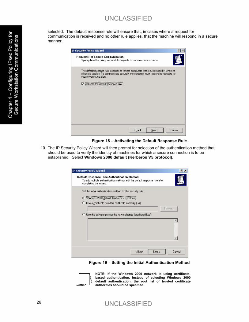
9. The IP Security Policy Wizard will then prompt for a response as to whether the default response rule should be activated. Make sure that the Activate the default response rule is
UNCLASSIFIED
UNCLASSIFIED 26
C
hapt
er 4
– C
onfig
urin
g IP
sec
Polic
y fo
r Se
cure
Wor
ksta
tion
Com
mun
icat
ions
selected. The default response rule will ensure that, in cases where a request for communication is received and no other rule applies, that the machine will respond in a secure manner.
Figure 18 – Activating the Default Response Rule
10. The IP Security Policy Wizard will then prompt for selection of the authentication method that should be used to verify the identity of machines for which a secure connection is to be established. Select Windows 2000 default (Kerberos V5 protocol).
Figure 19 – Setting the Initial Authentication Method
NOTE: If the Windows 2000 network is using certificate-based authentication, instead of selecting Windows 2000 default authentication, the root list of trusted certificate authorities should be specified.
UNCLASSIFIED
UNCLASSIFIED 27
C
hapter 4 – Configuring IPsec Policy for
Secure Workstation C
omm
unications
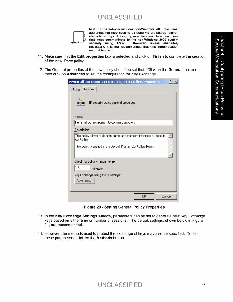
NOTE: If the network includes non-Windows 2000 machines, authentication may need to be done via pre-shared, secret, character strings. This string must be known to all machines that must communicate to the non-Windows 2000 system securely using IPsec. However, unless absolutely necessary, it is not recommended that this authentication method be used.
11. Make sure that the Edit properties box is selected and click on Finish to complete the creation of the new IPsec policy.
12. The General properties of the new policy should be set first. Click on the General tab, and
then click on Advanced to set the configuration for Key Exchange.
Figure 20 - Setting General Policy Properties
13. In the Key Exchange Settings window, parameters can be set to generate new Key Exchange keys based on either time or number of sessions. The default settings, shown below in Figure 21, are recommended.
14. However, the methods used to protect the exchange of keys may also be specified. To set
these parameters, click on the Methods button.

UNCLASSIFIED
UNCLASSIFIED 28
C
hapt
er 4
– C
onfig
urin
g IP
sec
Polic
y fo
r Se
cure
Wor
ksta
tion
Com
mun
icat
ions
Figure 21 – Setting the Methods to Protect the Exchange of Keys
15. Remove the DES/SHA1 and DES/MD5 options from the list of acceptable methods of
protecting key exchange transactions.
Figure 22 – Further Configuration of Key Exchange Security Methods
16. Click OK in both the Key Exchange Security Methods and Key Exchange Settings boxes to finish setting the General properties of the IPsec policy. Setting the General properties for the new IPsec policy is now complete.

UNCLASSIFIED
UNCLASSIFIED 29
C
hapter 4 – Configuring IPsec Policy for
Secure Workstation C
omm
unications
17. Click on the Rules tab in the IPsec policy properties window.
Figure 23 – Adding a New IP Security Rule
18. Click on Add to create a new IP security rule.
After clicking the Add rule button in the policy properties window, the security rule wizard will prompt for responses to several questions.
19. First, whether or not this rule is for an IPsec tunnel endpoint must be specified. For
communication within a domain, tunnel mode IPsec is not necessary, an IPsec transport mode connection is sufficient. Therefore, select This rule does not specify a tunnel.
Figure 24 – Specifying the Tunnel Endpoint
20. Next, the security rule wizard will request identification of the types of network connections to which this rule is to be applied. Select All network connections.

UNCLASSIFIED
UNCLASSIFIED 30
C
hapt
er 4
– C
onfig
urin
g IP
sec
Polic
y fo
r Se
cure
Wor
ksta
tion
Com
mun
icat
ions
Figure 25 – Selecting the Network Type
21. The security rule wizard will prompt for identification of the authentication type that is to be used to verify the identity of the machines that match this rule. Select Windows 2000 default (Kerberos V5 protocol).
Figure 26 – Selecting the Authentication Method
22. Next, the security rule wizard will request that a filter list be selected through which
communications can be identified as to whether they will be subject to this IPsec policy. Click Add to create a new IP filter list for communication between workstations and domain controllers.

UNCLASSIFIED
UNCLASSIFIED 31
C
hapter 4 – Configuring IPsec Policy for
Secure Workstation C
omm
unications
Figure 27 – Adding IP Filter List
23. The IP Filter List Wizard will request a name and description be supplied for this new filter list.
Provide a descriptive name and add detail in the description area provided.
Figure 28 – Naming the IP Filter List
24. Then click on Add to create a new filter within the filter list.
The IP Filter Wizard will start and will act as a guide through the process of creating the necessary filters.

UNCLASSIFIED
UNCLASSIFIED 32
C
hapt
er 4
– C
onfig
urin
g IP
sec
Polic
y fo
r Se
cure
Wor
ksta
tion
Com
mun
icat
ions
25. The first item that the IP Filter Wizard will request is the identification of the source address to which this filter should be applied. For simplicity sake, the wildcard My IP Address should be selected. This will ensure that, when the IPsec policy is propagated to any number of controllers in the domain, that the receiving machine will interpret this portion of the policy as applying to it. After selecting My IP Address, click next.
Figure 29 – Selecting the Source Address of the IP Traffic
26. The next item that the IP Filter Wizard will request is the identification of the destination address to which this filter should be applied. Again, for simplicity sake, the wildcard Any IP Address should be selected. This will ensure that each domain controller will use this rule to communicate will all other computers within the domain.
Figure 30 - Selecting the Destination Address of the IP Traffic
27. The IP Filter Wizard will request identification of the protocol types to which this filter should be
applied. Select Any as the protocol type to ensure that all IP communications are protected.

UNCLASSIFIED
UNCLASSIFIED 33
C
hapter 4 – Configuring IPsec Policy for
Secure Workstation C
omm
unications Figure 31 – Selecting the Protocol Type
28. The IP Filter Wizard is now complete. However, prior to clicking Finish, be sure to select the Edit properties box so that a final step may be performed.
29. Verify that the Mirrored box is selected and click OK.
Figure 32 - Verifying that "Mirrored" is Selected
Selecting the mirrored box instructs the IP Filter Wizard to configure the IPsec policy such that the same policy will be applied whether the domain controller initiates the communication or vice versa. This saves time in that a filter now does not need to be manually established for the second case.

UNCLASSIFIED
UNCLASSIFIED 34
C
hapt
er 4
– C
onfig
urin
g IP
sec
Polic
y fo
r Se
cure
Wor
ksta
tion
Com
mun
icat
ions
30. Verify that the new filter is correctly created (i.e., source address equals My IP Address and destination address equals Any IP Address). If correct, click Close.
31. Back in the Security Rule Wizard, select the radio button for the new filter list, then click Next.
Figure 33 - Selecting the New Filter List
32. Select the Permit radio button to allow all communication to domain controllers, then click Next.
Figure 34 -- Setting the Filter Action Behavior
33. Select the Edit Properties box and click Finish.
34. Review the new rule properties, ensuring that the new filter list is selected in the IP Filter List tab and the Permit action is selected in the Filter Action tab. If these are both true, click OK.

UNCLASSIFIED
UNCLASSIFIED 35
C
hapter 4 – Configuring IPsec Policy for
Secure Workstation C
omm
unications
35. Ensure that both the new (with Permit as the filter action) and <dynamic> (Default Response)
filter lists are selected in the IP Security Rules window. If this is true, click Close.
The new policy “Permit all communication to domain controllers” should now appear in the list of IP Security Policies on Active Directory.
Figure 35 - IP Security Policies on Active Directory Window After New Policy Creation
The new IPsec policy can now be applied to the Default Domain Controllers Policy.
36. To apply this policy, go back to the main window in the Management Console and click on the Console pull down menu and select Add/Remove Snap-in.
37. Click on Add in the Add/Remove Snap-in window.
38. Scroll down to the Group Policy snap-in and click Add.

UNCLASSIFIED
UNCLASSIFIED 36
C
hapt
er 4
– C
onfig
urin
g IP
sec
Polic
y fo
r Se
cure
Wor
ksta
tion
Com
mun
icat
ions
Figure 36 – The Group Policy Snap-In
39. Click Browse in the Select Group Policy Object window to search for the appropriate group
policy object.
Figure 37 – Selecting the Group Policy Object
40. Select Default Domain Controllers Policy and click OK. Then click Finish.
41. Under the Default Domain Controllers Policy entry in the management console, go down through the “Computer Configuration”, “Windows Settings”, and “Security Settings” entries and highlight IP Security Policies on Active Directory.
The list of defined IPsec policies will appear in the right side window (see Figure 38).

UNCLASSIFIED
UNCLASSIFIED 37
C
hapter 4 – Configuring IPsec Policy for
Secure Workstation C
omm
unications
Figure 38 - The Default Domain Controllers Group Policy Window
42. Right click on the desired IPsec policy (i.e., Permit all communication to domain controllers) and select Assign.
The status of the policy, as indicated under the Policy Assigned should change from No to Yes.
Figure 39 - Default Domain Controllers Group Policy with IPsec Policy Assigned

UNCLASSIFIED
UNCLASSIFIED 38
C
hapt
er 4
– C
onfig
urin
g IP
sec
Polic
y fo
r Se
cure
Wor
ksta
tion
Com
mun
icat
ions
43. Return to the IP Security Policies on Active Directory snap-in and again select Create IP Security Policy. This policy will specify secure communication among domain workstations.
44. When the IP Security Policy Wizard starts, provide a descriptive name that again gives some indication of the function of the policy. Provide additional details in the policy description window. Then click Next.
Figure 40 – IP Security Policy Wizard
45. Make sure that the Activate the default response rule is selected and click Next.
Figure 41 – Activating the Default Response Rule

UNCLASSIFIED
UNCLASSIFIED 39
C
hapter 4 – Configuring IPsec Policy for
Secure Workstation C
omm
unications
46. Select Windows 2000 default (Kerberos V5 protocol) as the authentication method.
Figure 42 – Setting the Initial Authentication Method
NOTE: If the Windows 2000 network is using certificate-based authentication, instead of selecting Windows 2000 default authentication, the root list of trusted certificate authorities should be specified.
NOTE: If the network includes non-Windows 2000 machines, authentication may need to be done via pre-shared, secret, character strings. This string must be known to all machines that must communicate to the non-Windows 2000 system securely using IPsec. However, unless absolutely necessary, it is not recommended that this authentication method be used.
47. Make sure that the Edit properties box is selected and click on Finish to complete the creation of the new IPsec policy.
48. The General properties of the new policy should be set first. Click on the General tab, and then click on Advanced to set the configuration for Key Exchange.
49. In the Key Exchange Settings window, parameters can be set to generate new Key Exchange keys based on either time or number of sessions. The default settings, shown below, are recommended.
50. However, the methods used to protect the exchange of keys may also be specified. To set these parameters, click on the Methods button.

UNCLASSIFIED
UNCLASSIFIED 40
C
hapt
er 4
– C
onfig
urin
g IP
sec
Polic
y fo
r Se
cure
Wor
ksta
tion
Com
mun
icat
ions
Figure 43 – Setting the Methods to Protect the Exchange of Keys
51. Again, remove the DES/SHA1 and DES/MD5 options from the list of acceptable methods of
protecting key exchange transactions.
Figure 44 – Further Configuration of Key Exchange Security Methods
52. Click OK in both the Key Exchange Security Methods and Key Exchange Settings boxes to finish setting the General properties of the IPsec policy. Setting the General properties for the new IPsec policy is now complete.
53. Click on the Rules tab in the IPsec policy properties window.
To properly configure IPsec communication among domain workstations, two types of rules must be created for this policy. The first type of rule will ensure that all workstations will be able to communicate with the domain controllers in the domain. As will be seen below, there will be a separate rule for each domain controller in the domain.
The second type of rule will specify the IPsec security parameters that are to be used to protect communication among all non-controller machines in the domain.

UNCLASSIFIED
UNCLASSIFIED 41
C
hapter 4 – Configuring IPsec Policy for
Secure Workstation C
omm
unications
54. Click on Add to create a new IP security rule and provide the following information to the
Security Rule Wizard.
55. For communication among domain workstations, tunnel mode IPsec is not necessary, an IPsec transport mode connection is sufficient. Therefore, select This rule does not specify a tunnel.
56. Next, the security rule wizard will request identification of the types of network connections to which this rule is to be applied. Select All network connections.
57. The security rule wizard will prompt for identification of the authentication type that is to be used to verify the identity of the machines that match this rule. Select Windows 2000 default (Kerberos V5 protocol).
58. Next, the security rule wizard will request that a filter list be selected through which communications can be identified as to whether they will be subject to this IPsec policy. Click Add to create a new IP filter list for communication between workstations and domain controllers.
Figure 45 – Adding IP Filter List
59. The IP Filter List Wizard will request a name and description be supplied for this new filter list. Provide a descriptive name and add detail in the description area provided.

UNCLASSIFIED
UNCLASSIFIED 42
C
hapt
er 4
– C
onfig
urin
g IP
sec
Polic
y fo
r Se
cure
Wor
ksta
tion
Com
mun
icat
ions
Figure 46 – Creating a New Filter Within the Filter List
60. Then click on Add to create a new filter within the filter list.
The IP Filter Wizard will start and will act as a guide through the process of creating the necessary filters.
61. For the identification of the source address to which this filter should be applied, select My IP Address. This will ensure that the receiving machine will interpret this portion of the policy as applying to it.
Figure 47 – Selecting the Source Address of the IP Traffic
62. For the destination address, the option of A specific IP Address should be selected and the IP address of one of the domain controllers should be provided.

UNCLASSIFIED
UNCLASSIFIED 43
C
hapter 4 – Configuring IPsec Policy for
Secure Workstation C
omm
unications Figure 48 – Selecting the Specific Destination Address for the IP Traffic
63. Lastly, select Any as the protocol type to ensure that all IP communications are protected.
Figure 49 – Selecting the Protocol Type
64. The IP Filter Wizard is now complete. However, prior to clicking Finish, be sure to select the
Edit properties box so that a final step may be performed.
65. Verify that the Mirrored box is selected and click OK.

UNCLASSIFIED
UNCLASSIFIED 44
C
hapt
er 4
– C
onfig
urin
g IP
sec
Polic
y fo
r Se
cure
Wor
ksta
tion
Com
mun
icat
ions
Figure 50 – Verifying that the Mirrored Option Box is Selected
The IP Filter List Wizard will return, and, if the filter was set correctly, should look like the following.
NOTE: The below window has been expanded beyond its default size to depict the relevant components of the IP filter. The default window size will not show the specific IP address designation for the destination address.
Figure 51 – Confirming the Filter is Set Correctly
66. The above procedure (steps 60-65) must now be repeated as many times as
necessary to create a similar rule for each domain controller in the domain.

UNCLASSIFIED
UNCLASSIFIED 45
C
hapter 4 – Configuring IPsec Policy for
Secure Workstation C
omm
unications
The following picture shows the IP filter list after the procedure has been repeated one time and shows the existence of filter lists for two domain controllers.
Figure 52 – Example of Repeated Procedure
67. After the filters for all the domain controllers have been created, close the IP Filters List window and return to the Security Rule Wizard. Select the radio button for the new filter list, then click Next.
Figure 53 - Selecting the New Filter List
68. Select the Permit filter action and click Next. Then make sure the edit properties check box is selected and click Finish.
69. Verify that the new filter list and appropriate filter action are selected. If so, click OK.
70. Back in the policy Properties window, select Add to create a 2nd rule.
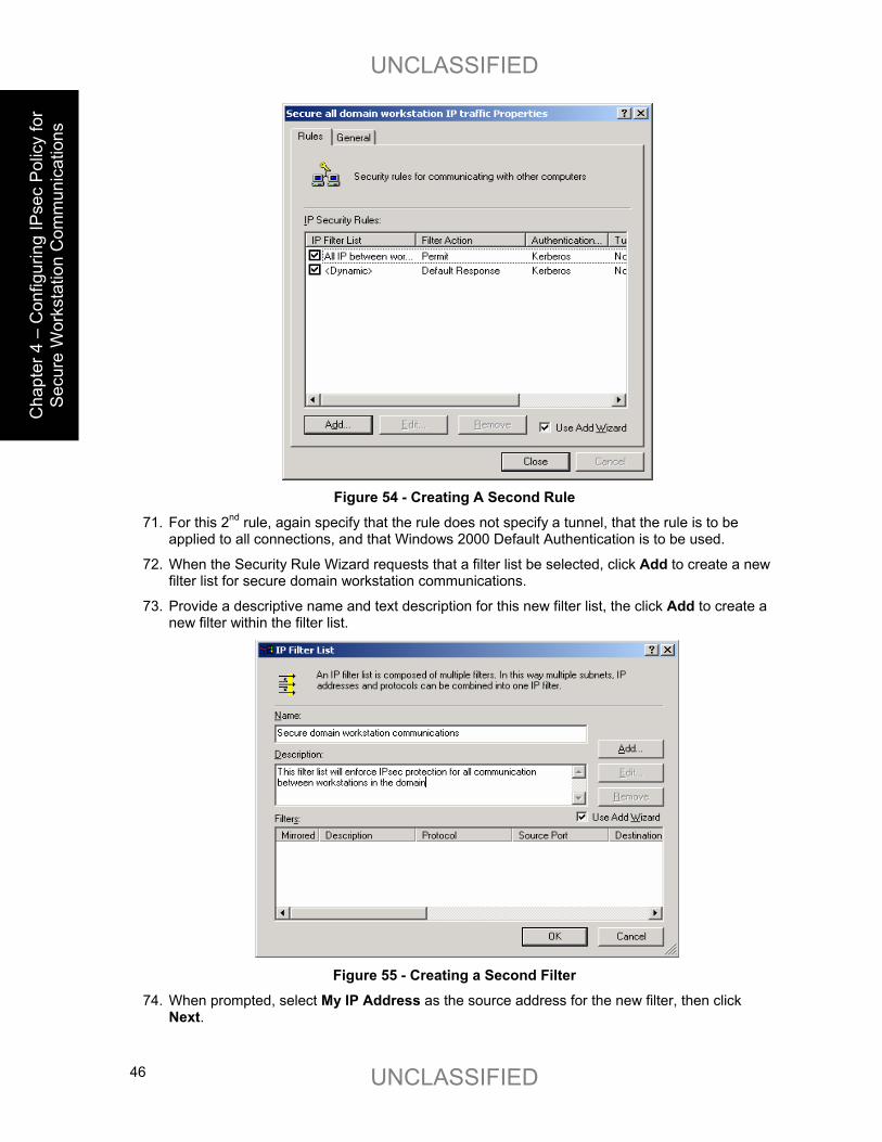
UNCLASSIFIED
UNCLASSIFIED 46
C
hapt
er 4
– C
onfig
urin
g IP
sec
Polic
y fo
r Se
cure
Wor
ksta
tion
Com
mun
icat
ions
Figure 54 - Creating A Second Rule
71. For this 2nd rule, again specify that the rule does not specify a tunnel, that the rule is to be applied to all connections, and that Windows 2000 Default Authentication is to be used.
72. When the Security Rule Wizard requests that a filter list be selected, click Add to create a new filter list for secure domain workstation communications.
73. Provide a descriptive name and text description for this new filter list, the click Add to create a new filter within the filter list.
Figure 55 - Creating a Second Filter
74. When prompted, select My IP Address as the source address for the new filter, then click Next.

UNCLASSIFIED
UNCLASSIFIED 47
C
hapter 4 – Configuring IPsec Policy for
Secure Workstation C
omm
unications
75. Select Any IP Address as the destination address for the new filter, then click Next. 76. Select Any for the protocol to which the new filter applies.
77. Then, via checking the Edit Properties box prior to clicking Finish, ensure that the Mirrored check box is selected. The filter list for this IPsec policy is now complete.
78. In the IP Filter List window, check to ensure that the filter has been created correctly (e.g., source address equals My IP Address and destination address equals Any IP Address. If correct, click Close.
Now that the filter list for secure workstation communication is complete, the next step is to select the filter action for this filter list.
79. Back in the Security Rule Wizard, select the radio button for the new filter list (“Secure domain workstation communications”), then click Next.
The security rule wizard will next prompt for the selection of a filter action (i.e., the action that is to be taken when an IP packet matches the filter). It is recommended that a new action be created for this policy.
80. Click on Add in the Security Rule Wizard Filter Action window.
Figure 56 – Adding a New Action
The filter action wizard will start and will request a name and description be provided for the new action.
81. Provide a descriptive name and sufficient description to understand how the action works, and click on Next.

UNCLASSIFIED
UNCLASSIFIED 48
C
hapt
er 4
– C
onfig
urin
g IP
sec
Polic
y fo
r Se
cure
Wor
ksta
tion
Com
mun
icat
ions
Figure 57 – Naming and Describing the New Action
82. Accept the default setting of Negotiate Security and click Next.
Figure 58 -- Setting the Filter Action Behavior
NOTE: The “Permit” option automatically allows the communication without invoking any IPsec security. The “Block” option automatically prevents the communication regardless of whether or not the parties are capable of communicating securely via IPsec.
In order to ensure that all workstation communication is done securely, no fallback to unsecured communication can be allowed.

UNCLASSIFIED
UNCLASSIFIED 49
C
hapter 4 – Configuring IPsec Policy for
Secure Workstation C
omm
unications
83. Accept the default setting Do not communicate with computers that do not support IPsec and click Next.
Figure 59 – Ensuring no Communication with Computers that don’t support IPsec
84. The next window will request that a security level be specified. Select the Custom, then click
on Settings.
Figure 60 – Specifying Security Level
85. Select the setting to provide both data integrity (via MD5) and encryption (via 3DES). Also, select the setting to generate a new encryption key every 3600 seconds (1 hour). Then click OK.

UNCLASSIFIED
UNCLASSIFIED 50
C
hapt
er 4
– C
onfig
urin
g IP
sec
Polic
y fo
r Se
cure
Wor
ksta
tion
Com
mun
icat
ions
Figure 61 - Customizing Security Level
86. Click Next to close the Security Method Wizard.
87. Select the Edit Properties box and click Finish to close the new filter action wizard.
88. Back in the new Filter Action Properties window, click Add.
89. Again, select Custom, the click Settings.
90. Specify SHA1, 3DES, and generate key every 3600 seconds, and click OK.
91. Click OK in the new Security Method window.
92. In the New Filter Action Properties window, the negotiate security radio button should be selected and the 3DES/MD5 and 3DES/SHA1 security methods should be listed.
93. Clear the Accept unsecured communication, but always respond using IPsec box.
94. If both actions are shown in the New Filter Action Properties window and the check box is cleared, click OK.
The new filter action is now created and can be selected for use in the IPsec filter.
95. Select the Demand Security radio button and click Next.

UNCLASSIFIED
UNCLASSIFIED 51
C
hapter 4 – Configuring IPsec Policy for
Secure Workstation C
omm
unications Figure 62 – Selecting the New Filter Action
96. Ensure that the Edit Properties box is selected and click Finish.
97. Review the new rule properties, ensuring that the new filter list is selected in the IP Filter List tab and the new action is selected in the Filter Action tab. If these are both true, click OK.
98. Ensure that all 3 security rules are selected in the IP Security Rules window. If this is true, click Close.
Figure 63 – Ensuring the New and Default Filter Lists are Selected
The Management Console should now look like Figure 64. The new IPsec policy for securing
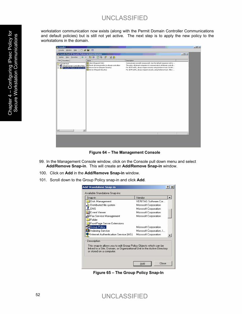
UNCLASSIFIED
UNCLASSIFIED 52
C
hapt
er 4
– C
onfig
urin
g IP
sec
Polic
y fo
r Se
cure
Wor
ksta
tion
Com
mun
icat
ions
workstation communication now exists (along with the Permit Domain Controller Communications and default policies) but is still not yet active. The next step is to apply the new policy to the workstations in the domain.
Figure 64 – The Management Console
99. In the Management Console window, click on the Console pull down menu and select
Add/Remove Snap-in. This will create an Add/Remove Snap-in window.
100. Click on Add in the Add/Remove Snap-in window.
101. Scroll down to the Group Policy snap-in and click Add.
Figure 65 – The Group Policy Snap-In

UNCLASSIFIED
UNCLASSIFIED 53
C
hapter 4 – Configuring IPsec Policy for
Secure Workstation C
omm
unications
102. Click Browse in the Select Group Policy Object window to search for the appropriate group policy object.
Figure 66 – Selecting the Group Policy Object
103. Select Default Domain Policy and click OK. Then click Finish.
Figure 67 – Selecting the Default Domain Policy
104. Close the Add Standalone Snap-in window.
105. Then close the Add/Remove Snap-in window by clicking OK.

UNCLASSIFIED
UNCLASSIFIED 54
C
hapt
er 4
– C
onfig
urin
g IP
sec
Polic
y fo
r Se
cure
Wor
ksta
tion
Com
mun
icat
ions
Figure 68 – Closing the Add/Remove Snap-In Window
106. Click on the Default Domain Policy line to expand the view to show details down through the Computer Configuration, Windows Settings, and Security Settings sub-levels.
107. Highlight the IP Security Policies on Active Directory entry.
The IPsec policies that are defined should appear in the right side window. All policies should show that they are not assigned (i.e., not active).
NOTE: While the “Permit all Communication to Domain Controllers” IPsec policy is active in the Default Domain Controllers Policy, that will not be indicated here.
Figure 69 – IP Security Policies on Active Directory
108. Highlight the new IPsec policy by clicking on it one time.

UNCLASSIFIED
UNCLASSIFIED 55
C
hapter 4 – Configuring IPsec Policy for
Secure Workstation C
omm
unications
Figure 70 – Highlighting the New IPsec Policy
109. Go to the Action pull down menu and select Assign.
Figure 71 – Assigning the New IPsec Policy
The status of the new policy, indicated under the Policy Assigned field, should change from No (unassigned, not active) to Yes (assigned, active).

UNCLASSIFIED
UNCLASSIFIED 56
C
hapt
er 4
– C
onfig
urin
g IP
sec
Polic
y fo
r Se
cure
Wor
ksta
tion
Com
mun
icat
ions
Figure 72 – Confirming the Policy has been Assigned
The new IPsec policy is now assigned (in effect) in the domain.
It may take some time for the new policy to propagate to all machines in the domain. However, after the propagation is complete, all communication among non-controller machines will be protected (confidentiality and integrity) by IPsec.
The last recommended step is to save the current instance of the management console. This will allow quick and easy access to IPsec settings in the future.
110. Click on the Console pull down menu and select Save as. Provide a name for this console instance (something along the lines of “IPsec policy management”) and save it on the desktop.

UNCLASSIFIED
UNCLASSIFIED 57
C
hapter 4 – Configuring IPsec Policy for
Secure Workstation C
omm
unications
Figure 73 – Confirming the Policy has been Assigned

UNCLASSIFIED
UNCLASSIFIED 58
This Page Intentionally Left Blank

UNCLASSIFIED
UNCLASSIFIED 59
C
hapter 5 – Configuring IPsec Policy for
Secure Dom
ain Controller C
omm
unications
Chapter
5 Configuring IPsec Policy for Secure Domain Controller Communications
This chapter presents step-by-step instructions for configuring IPsec policy for providing secured communications among all domain controller machines within a Windows 2000 domain. The policy will include protection from unwanted disclosure and modification through the provision of the encryption and integrity mechanisms provided by IPsec.
The procedures outlined in this chapter can be used as a guide from which different security needs can also be satisfied through the creation of different IPsec policies.
The procedures described in this chapter are very similar to the procedures in the examples in Chapter 4. However, for thoroughness, and to allow the chapter to stand on its own, the complete process, not just the differences, is presented. There are a number of important differences between the procedures for the example in Chapter 4 (IPsec policy for non-controller machines) and this chapter (IPsec policy for domain controller communications).
Setting up the IPsec Policy
This example was done with Windows 2000 versions (advanced server, server, and professional) loaded with Service Pack 1 and the High Encryption pack. These upgrades (i.e., Service Pack 1 and the High Encryption pack) must be loaded prior to creating the IPsec policy.
NOTE: The high encryption pack must be installed to use 3DES. If the high encryption pack is not installed, the system will log the fact that 3DES was not used and will automatically downgrade the IPsec encryption to DES.
1. To start the Management Console, select Run from the start menu, type mmc in the run window that appears, and click OK.

UNCLASSIFIED
UNCLASSIFIED 60
Cha
pter
5 –
Con
figur
ing
IPse
c Po
licy
for S
ecur
e D
omai
n C
ontro
ller C
omm
unic
atio
ns
Figure 73 – Starting the Management Console
2. A management console window will appear. Pull down the Console menu at the top of the
window, and select Add/Remove Snap-in.
Figure 74 – Selecting Add/Remove Snap-in
3. Click on Add in the Add/Remove Snap-in window to get the list of available snap-ins.

UNCLASSIFIED
UNCLASSIFIED 61
C
hapter 5 – Configuring IPsec Policy for
Secure Dom
ain Controller C
omm
unications
Figure 75 – Viewing Available Snap-Ins
4. In the Add Standalone Snap-in window, scroll down to and select IP Security Policy Management, and click the Add button.
Figure 76 – Selecting IP Security Policy Management
5. The next window will request specification of whether the IP Security Policy Management snap-in is for managing the IPsec policy for the local computer, for the domain in which this computer

UNCLASSIFIED
UNCLASSIFIED 62
Cha
pter
5 –
Con
figur
ing
IPse
c Po
licy
for S
ecur
e D
omai
n C
ontro
ller C
omm
unic
atio
ns
is a member, another domain, or another computer. Select Manage domain policy for this computer’s domain and click on the Finish button.
Figure 77 – Selecting Which Computer the Snap-in will Manage
6. Click Close in the Add Standalone Snap-in window, and click OK in the Add/Remove Snap-in window.
Figure 78 – Resulting Management Console
7. Highlight the IP Security Policies on Active Directory snap-in by clicking on it one time. Then go to the action tab and select Create IP Security Policy.

UNCLASSIFIED
UNCLASSIFIED 63
C
hapter 5 – Configuring IPsec Policy for
Secure Dom
ain Controller C
omm
unications Figure 79 – Creating an IP Security Policy
8. The IP Security Policy Wizard will start, click Next to get to the Policy Name Screen which will request a name for and description of the new policy. Provide a descriptive name that gives some indication of the function of the policy. Click Next when finished.
Figure 80 – Naming and Describing the New Security Policy
9. The IP Security Policy Wizard will then prompt for a response as to whether the default response rule should be activated. Make sure that the Activate the default response rule is selected. The default response rule will ensure that, in cases where a request for
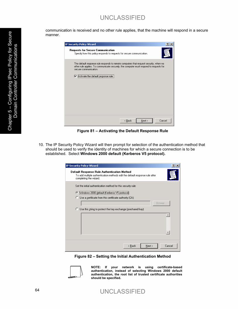
UNCLASSIFIED
UNCLASSIFIED 64
Cha
pter
5 –
Con
figur
ing
IPse
c Po
licy
for S
ecur
e D
omai
n C
ontro
ller C
omm
unic
atio
ns
communication is received and no other rule applies, that the machine will respond in a secure manner.
Figure 81 – Activating the Default Response Rule
10. The IP Security Policy Wizard will then prompt for selection of the authentication method that should be used to verify the identity of machines for which a secure connection is to be established. Select Windows 2000 default (Kerberos V5 protocol).
Figure 82 – Setting the Initial Authentication Method
NOTE: If your network is using certificate-based authentication, instead of selecting Windows 2000 default authentication, the root list of trusted certificate authorities should be specified.

UNCLASSIFIED
UNCLASSIFIED 65
C
hapter 5 – Configuring IPsec Policy for
Secure Dom
ain Controller C
omm
unications
NOTE: If your network includes non-Windows 2000 machines, authentication may need to be done via pre-shared, secret, character strings. This string must be known to all machines which must communicate to the non-Windows 2000 system securely using IPsec. However, unless absolutely necessary, it is not recommended that this authentication method be used.
11. Make sure that the Edit properties box is selected and click on Finish to complete the creation of the new IPsec policy.
12. The General properties of the new policy should be set first. Click on the General tab, and
then click on Advanced to set the configuration for Key Exchange.
Figure 83 – Setting the Configuration for Key Exchange
13. In the Key Exchange Settings window, parameters can be set to generate new Key Exchange
keys based on either time or number of sessions. The default settings are recommended.
14. However, the methods used to protect the exchange of keys may also be specified. To set these parameters, click on the Methods button.

UNCLASSIFIED
UNCLASSIFIED 66
Cha
pter
5 –
Con
figur
ing
IPse
c Po
licy
for S
ecur
e D
omai
n C
ontro
ller C
omm
unic
atio
ns
Figure 84 – Setting the Methods to Protect the Exchange of Keys
15. Remove the DES/SHA1 and DES/MD5 options from the list of acceptable methods of
protecting key exchange transactions.
Figure 85 – Further Configuration of Key Exchange Security Methods
16. Click OK in both the Key Exchange Security Methods and Key Exchange Settings boxes to
finish setting the General properties of the IPsec policy. Setting the General properties for the new IPsec policy is now complete.
17. Open the Rules tab in the IPsec policy properties window.
18. Click on Add to create a new IP security rule. After clicking the Add rule button in the policy properties window, the security rule wizard will prompt for responses to several questions.
19. First, whether or not this rule is for an IPsec tunnel endpoint must be specified. For
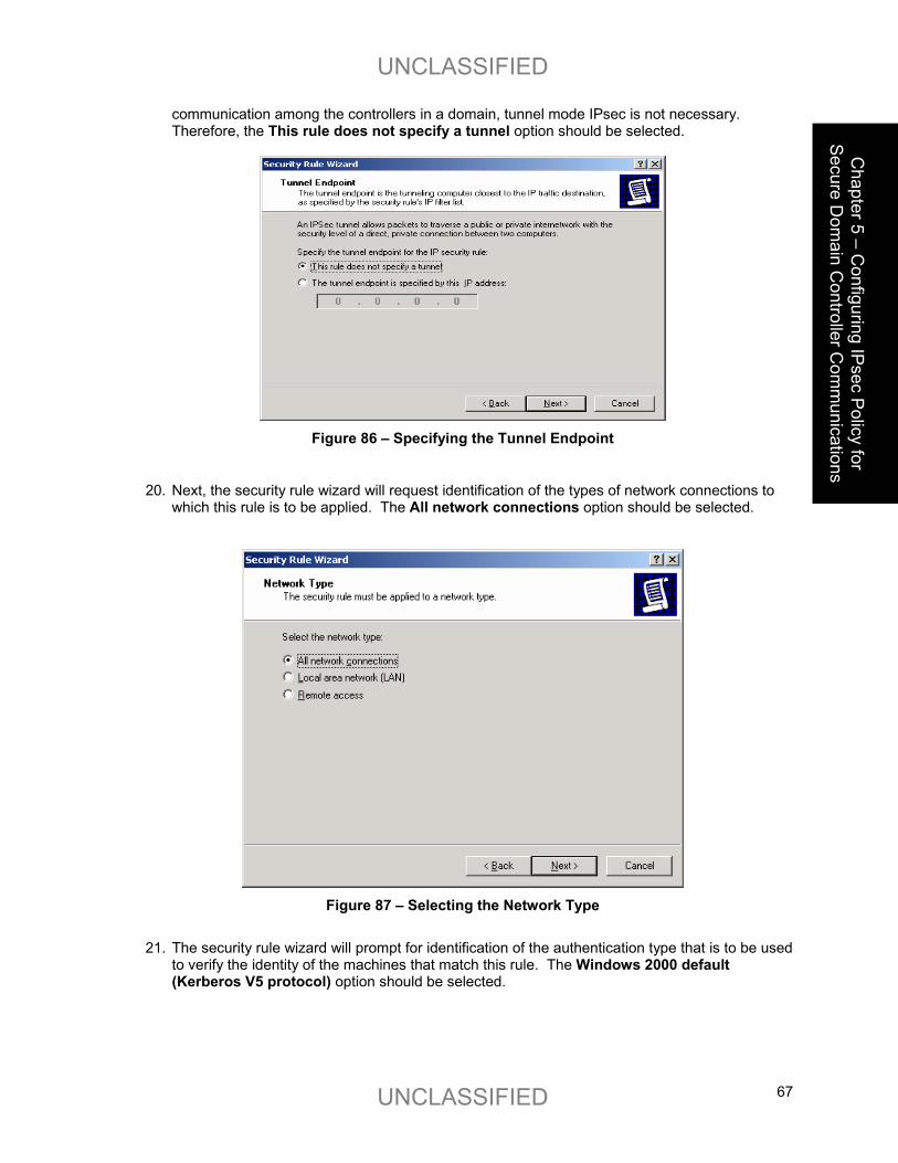
UNCLASSIFIED
UNCLASSIFIED 67
C
hapter 5 – Configuring IPsec Policy for
Secure Dom
ain Controller C
omm
unications
communication among the controllers in a domain, tunnel mode IPsec is not necessary. Therefore, the This rule does not specify a tunnel option should be selected.
Figure 86 – Specifying the Tunnel Endpoint
20. Next, the security rule wizard will request identification of the types of network connections to which this rule is to be applied. The All network connections option should be selected.
Figure 87 – Selecting the Network Type
21. The security rule wizard will prompt for identification of the authentication type that is to be used
to verify the identity of the machines that match this rule. The Windows 2000 default (Kerberos V5 protocol) option should be selected.

UNCLASSIFIED
UNCLASSIFIED 68
Cha
pter
5 –
Con
figur
ing
IPse
c Po
licy
for S
ecur
e D
omai
n C
ontro
ller C
omm
unic
atio
ns
Figure 88 – Selecting the Authentication Method
22. Next, the security rule wizard will request that a filter list be selected through which communications can be identified as to whether they will be subject to this IPsec policy. Click Add to create a new IP filter list for communication between domain controllers.
Figure 89 – Adding IP Filter List
23. The IP Filter List Wizard will request a name and description be supplied for this new filter list. Provide a descriptive name and add detail in the description area provided.
24. Then click on Add to create the new filter within the filter list. Then click Next to begin.

UNCLASSIFIED
UNCLASSIFIED 69
C
hapter 5 – Configuring IPsec Policy for
Secure Dom
ain Controller C
omm
unications Figure 90 – Naming and Adding the New Filter
The IP Filter Wizard will start and will act as a guide through the process of creating the necessary filters.
25. The first item that the IP Filter Wizard will request is the identification of the source address to
which this filter should be applied. For simplicity sake, the wildcard My IP Address should be selected. This will ensure that, when the IPsec policy is propagated to all domain controllers in the domain, the receiving machine will interpret this portion of the policy as applying to it. After selecting My IP Address, click Next.
Figure 91 – Selecting the Source Address for the IP Traffic
26. The IP Filter Wizard will then request that the destination address be identified. Here, the
option of “A specific IP Address” should be selected and the IP address of one of the domain controllers should be provided.

UNCLASSIFIED
UNCLASSIFIED 70
Cha
pter
5 –
Con
figur
ing
IPse
c Po
licy
for S
ecur
e D
omai
n C
ontro
ller C
omm
unic
atio
ns
Figure 92 – Selecting the Specific Destination Address for the IP Traffic
27. The IP Filter Wizard will then request identification of the protocol types to which this filter should be applied. Any should be specified as the protocol type to ensure that all IP communications are protected.
Figure 93 – Selecting a Protocol Type
The IP Filter Wizard is now complete. However, prior to clicking on Finish, be sure to select the Edit properties box so that a final step may be performed.
28. Verify that the Mirrored box is selected and click OK.

UNCLASSIFIED
UNCLASSIFIED 71
C
hapter 5 – Configuring IPsec Policy for
Secure Dom
ain Controller C
omm
unications
Figure 94 – Verifying that the Mirrored Option is Selected
Selecting the mirrored box instructs the IP Filter Wizard to configure the IPsec policy such that the same policy will be applied regardless of which domain controller initiates the communication.
The IP Filter List Wizard, which, if the filter was set correctly, should look like the following.
NOTE: The below window has been expanded beyond its default size to depict the relevant components of the IP filter. The default window size will not show the specific IP address designation for the destination address.
Figure 95 – Confirming the Filter is Set Correctly
29. The above procedure (steps 24-28) must now be repeated as many times as necessary to create a similar rule for each domain controller in the domain.
The following picture shows the IP filter list after the procedure has been repeated one time and shows the existence of filter lists for two domain controllers.

UNCLASSIFIED
UNCLASSIFIED 72
Cha
pter
5 –
Con
figur
ing
IPse
c Po
licy
for S
ecur
e D
omai
n C
ontro
ller C
omm
unic
atio
ns
Figure 96 – Example of Repeated Procedure
Once a filter exists for all domain controllers, the filter list for this IPsec policy is complete. Now that the filter list is complete, the next step is to select the new filter list as the one to be applied for this IPsec policy. Click Close to return to the Security Rule Wizard.
30. In the Security Rule Wizard, select the radio button for the new filter list, and then click Next.
Figure 97 – Reviewing the New Filter List
The security rule wizard will next prompt for the selection of a filter action (i.e., the action that is to be taken when an IP packet matches the filter). It is recommended that a new action be created for this policy.
31. Click on Add in the Security Rule Wizard Filter Action window.

UNCLASSIFIED
UNCLASSIFIED 73
C
hapter 5 – Configuring IPsec Policy for
Secure Dom
ain Controller C
omm
unications
Figure 98 – Adding a New Action
The filter action wizard will start and will request a name and description be provided for the new action.
32. Provide a descriptive name and sufficient description to understand how the action works, and
click on Next.
Figure 99 – Naming and Describing the New Action
33. Accept the default setting of Negotiate Security and click Next.

UNCLASSIFIED
UNCLASSIFIED 74
Cha
pter
5 –
Con
figur
ing
IPse
c Po
licy
for S
ecur
e D
omai
n C
ontro
ller C
omm
unic
atio
ns
Figure 100 – Setting the Filter Action Behavior
NOTE: The “Permit” option automatically allows the communication without invoking any IPsec security. The “Block” option automatically prevents the communication regardless of whether or not the parties are capable of communicating securely via IPsec.
In order to ensure that all domain controllers will continue to communicate until the new policy is propagated to all domain controllers in the domain, fallback to unsecured communication should be selected. As will be seen in a later step, after sufficient time has passed that the policy has been pushed down to all domain controllers, the fallback to unsecured communication option should be removed.
34. Select the Fallback to unsecured communication setting and click Next.
Figure 101 – Ensuring Continued Communication
35. The next window will request that a security level be specified. Select the Custom radio button, and then click on Settings.

UNCLASSIFIED
UNCLASSIFIED 75
C
hapter 5 – Configuring IPsec Policy for
Secure Dom
ain Controller C
omm
unications
Figure 102 – Specifying Security Level
36. Select the setting to provide both data integrity (via MD5 or SHA) and encryption (via
3DES). Also, select the setting to generate a new encryption key every 3600 seconds (1 hour). Click OK to return to the Security Method Wizard and click Next to continue.
Figure 103 – Customizing Security Level
37. Select the Edit Properties box and click Finish to complete the creation of the new filter
action.
38. Clear the Accept unsecured communication, but always respond using IPsec box, leaving only the Allowed unsecured communication with non IPsec-aware computers selected. Click OK.

UNCLASSIFIED
UNCLASSIFIED 76
Cha
pter
5 –
Con
figur
ing
IPse
c Po
licy
for S
ecur
e D
omai
n C
ontro
ller C
omm
unic
atio
ns
Figure 104 – Further Configuration of Security Methods
The new filter action is now created and can be selected for use in the IPsec filter.
39. Select the Require security for DCs radio button and click Next.
Figure 105 – Selecting the Filter Action for the Security Rule
40. Ensure that the Edit Properties box is selected and click Finish.
41. Review the new rule properties, ensuring that the new filter list is selected in the IP Filter List tab and the new action is selected in the Filter Action tab. If these are both true, click OK.

UNCLASSIFIED
UNCLASSIFIED 77
C
hapter 5 – Configuring IPsec Policy for
Secure Dom
ain Controller C
omm
unications
Figure 106 – Ensuring the Filter List and Action are Selected
42. After returning to the policy properties window, ensure that both the new (All IP Between
Domain Controllers) and default (Default Response) filter lists are selected in the IP Security Rules window. If this is true, click Close.
Figure 107 – Ensuring the New and Default Filter Lists are Selected
The Management Console should now look like Figure 108. The new IPsec policy for securing domain controller communications now exists (along with the three default policies). The next step of the process is to apply the new policy to the controllers in the domain.
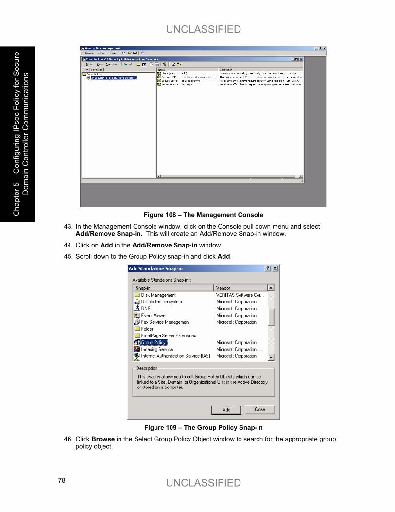
UNCLASSIFIED
UNCLASSIFIED 78
Cha
pter
5 –
Con
figur
ing
IPse
c Po
licy
for S
ecur
e D
omai
n C
ontro
ller C
omm
unic
atio
ns
Figure 108 – The Management Console
43. In the Management Console window, click on the Console pull down menu and select Add/Remove Snap-in. This will create an Add/Remove Snap-in window.
44. Click on Add in the Add/Remove Snap-in window.
45. Scroll down to the Group Policy snap-in and click Add.
Figure 109 – The Group Policy Snap-In
46. Click Browse in the Select Group Policy Object window to search for the appropriate group policy object.

UNCLASSIFIED
UNCLASSIFIED 79
C
hapter 5 – Configuring IPsec Policy for
Secure Dom
ain Controller C
omm
unications
Figure 110 – Selecting the Group Policy Object
47. Select Domain Controllers folder by double clicking on it. Then select the Default Domain Policy and click OK. Then click Finish.
Figure 100 - Selecting the Default Domain Policy
48. Close the Add Standalone Snap-in window. 49. Then close the Add/Remove Snap-in window by clicking OK.

UNCLASSIFIED
UNCLASSIFIED 80
Cha
pter
5 –
Con
figur
ing
IPse
c Po
licy
for S
ecur
e D
omai
n C
ontro
ller C
omm
unic
atio
ns
Figure 111 – Closing the Add/Remove Snap-in Window
The resulting management console window should look like the following:
Figure 112 – Resulting Management Console Window

UNCLASSIFIED
UNCLASSIFIED 81
C
hapter 5 – Configuring IPsec Policy for
Secure Dom
ain Controller C
omm
unications
50. Click on the Default Domain Controllers Policy line and expand the view to show details
down through the Computer Configuration, Windows Settings, and Security Settings sub-levels.
51. Highlight the IP Security Policies on Active Directory entry.
The IPsec policies that are defined (three default policies and the new one which was just created) should appear in the right side window. All policies should show that they are not assigned (i.e., not active).
Figure 113 – IP Security Policies on Active Directory
52. Highlight the new IPsec policy by clicking on it one time.

UNCLASSIFIED
UNCLASSIFIED 82
Cha
pter
5 –
Con
figur
ing
IPse
c Po
licy
for S
ecur
e D
omai
n C
ontro
ller C
omm
unic
atio
ns
Figure 114 – Highlighting the New IPsec Policy
53. Go to the Action pull down menu and select Assign.
Figure 105 - Assigning the New IPsec Policy

UNCLASSIFIED
UNCLASSIFIED 83
C
hapter 5 – Configuring IPsec Policy for
Secure Dom
ain Controller C
omm
unications
The status of the new policy, indicated under the “Policy Assigned” field, should change from “No” (unassigned, not active) to “Yes” (assigned, active).
Figure 115 – Confirming the Policy has been Assigned
The new IPsec policy is now assigned (in effect) in the domain.
It may take several minutes for the new policy to propagate to all domain controllers in the domain. However, after the propagation is complete, all communication among domain controller machines will be protected (via encryption and integrity) by IPsec.
If communication between a domain controller that has received the new policy and one that has not received it is required, the fallback to unsecured option will allow the controllers to communicate. This is only an interim situation until all domain controllers receive the new IPsec policy.
54. Click on the Console pull down menu and select Save as. Provide a name for this console instance (something along the lines of “IPsec policy management”) and save it on the desktop.
Figure 116 – Saving and Naming the Console
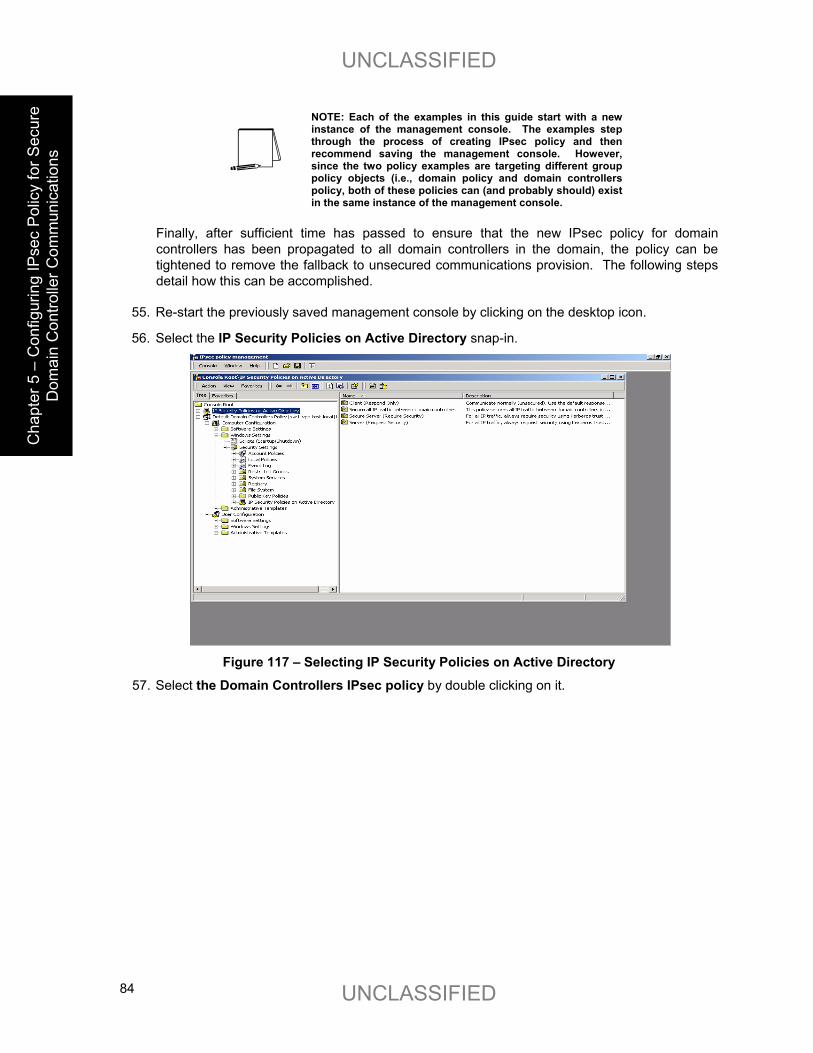
UNCLASSIFIED
UNCLASSIFIED 84
Cha
pter
5 –
Con
figur
ing
IPse
c Po
licy
for S
ecur
e D
omai
n C
ontro
ller C
omm
unic
atio
ns
NOTE: Each of the examples in this guide start with a new instance of the management console. The examples step through the process of creating IPsec policy and then recommend saving the management console. However, since the two policy examples are targeting different group policy objects (i.e., domain policy and domain controllers policy, both of these policies can (and probably should) exist in the same instance of the management console.
Finally, after sufficient time has passed to ensure that the new IPsec policy for domain controllers has been propagated to all domain controllers in the domain, the policy can be tightened to remove the fallback to unsecured communications provision. The following steps detail how this can be accomplished.
55. Re-start the previously saved management console by clicking on the desktop icon.
56. Select the IP Security Policies on Active Directory snap-in.
Figure 117 – Selecting IP Security Policies on Active Directory
57. Select the Domain Controllers IPsec policy by double clicking on it.
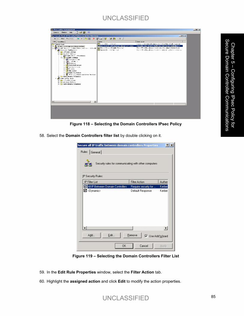
UNCLASSIFIED
UNCLASSIFIED 85
C
hapter 5 – Configuring IPsec Policy for
Secure Dom
ain Controller C
omm
unications
Figure 118 – Selecting the Domain Controllers IPsec Policy
58. Select the Domain Controllers filter list by double clicking on it.
Figure 119 – Selecting the Domain Controllers Filter List
59. In the Edit Rule Properties window, select the Filter Action tab.
60. Highlight the assigned action and click Edit to modify the action properties.

UNCLASSIFIED
UNCLASSIFIED 86
Cha
pter
5 –
Con
figur
ing
IPse
c Po
licy
for S
ecur
e D
omai
n C
ontro
ller C
omm
unic
atio
ns
Figure 120 – Modifying Action Properties
61. Un-select the Allow unsecured communication with non IPsec-aware computers option.
Then click OK.
Figure 121 – Not Allowing Unsecured Communication
62. Then click Close in both the Edit Rule Properties and policy properties windows.

UNCLASSIFIED
UNCLASSIFIED 87
C
hapter 5 – Configuring IPsec Policy for
Secure Dom
ain Controller C
omm
unications
The new settings for the IPsec policy will be propagated to all domain controllers through the normal policy propagation process. This may take several minutes but, once complete, all domain controller communications will then be completely secured.

UNCLASSIFIED
UNCLASSIFIED 88
This Page Intentionally Left Blank
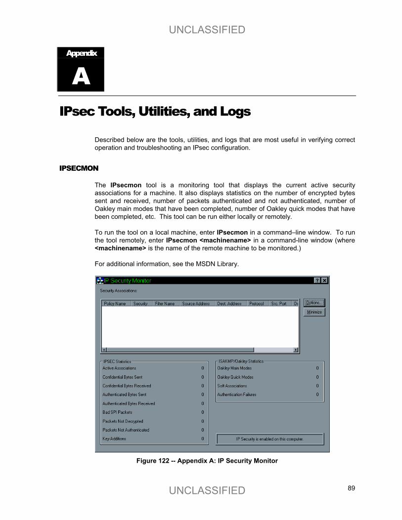
UNCLASSIFIED
UNCLASSIFIED 89
Appendix
A IPsec Tools, Utilities, and Logs
Described below are the tools, utilities, and logs that are most useful in verifying correct operation and troubleshooting an IPsec configuration.
IPSECMON
The IPsecmon tool is a monitoring tool that displays the current active security associations for a machine. It also displays statistics on the number of encrypted bytes sent and received, number of packets authenticated and not authenticated, number of Oakley main modes that have been completed, number of Oakley quick modes that have been completed, etc. This tool can be run either locally or remotely.
To run the tool on a local machine, enter IPsecmon in a command–line window. To run the tool remotely, enter IPsecmon <machinename> in a command-line window (where <machinename> is the name of the remote machine to be monitored.)
For additional information, see the MSDN Library.
Figure 122 -- Appendix A: IP Security Monitor

UNCLASSIFIED
UNCLASSIFIED 90
NETDIAG
Netdiag is a utility that can be used to test networking and connectivity capability on a machine. Although this utility has additional functionality, it can be used specifically to check whether or not IPsec is enabled on the machine, and if so, to display the IPsec policies in place for the machine.
Netdiag is not automatically installed on a machine. This utility must be loaded from the \Support\Tools directory of a Windows 2000 operating system CD. For detailed instructions on installing and running this tool, see the sreadme.doc file located in the \Support\Tools directory.
Once netdiag has been installed, it can be used to provide detailed information on a variety of network and connectivity related items, including IPsec. To run a check on the status of IPsec on a machine, go to the Start menu, and select Programs->Windows 2000 Support Tools -> Tools -> Command Prompt.
In the command-line window that appears, type netdiag /test:IPsec /v and hit enter. A listing will be given showing detailed information about the machine’s network connection, domain information, and IPsec policy (if one is enabled.) Included in the information about the policy will be the name of the policy, statistics about packets passed since the policy was enabled, the encryption being used, etc.
This utility is mainly useful for verifying the appropriate policy has been assigned to each machine, and for verifying details of the policy that was enabled, including which filters in the policy apply to that machine, and what those filters look like.
Netdiag must be run locally on the machine being checked.
Oakley Logs
It is possible to enable detailed logging of the IKE dialogue between machines when a security association is being established. This logging is enabled on a single machine, and a log of every IKE transaction between that machine and any other machine is logged. The log created is the Oakley log, and it can be a useful tool in verifying that SAs are being established correctly, and in troubleshooting when SA establishment is failing unexpectedly.
Enabling the Oakley log requires an administrator to modify the registry.
WARNING: modification of the registry must be done with extreme caution, as an incorrect modification can render the system inoperable, requiring a complete reload of the operating system. The administrator should back up the registry before making any modifications to it. The administrator should also update the Emergency Repair Disk prior to making these modifications.
Event Logs/Auditing
A limited amount of information about the status of an IPsec configuration is automatically logged in the event logs when IPsec is enabled on a system.

UNCLASSIFIED
UNCLASSIFIED 91
1. The base standard, Security Architecture for the Internet Protocol, is documented in IETF RFC 2401 (http://www.ietf.org/rfc/rfc2401.txt).
2. More information on the definition of the AH protocol and its security services can be found in IP Authentication Header, IETF RFC 2402, http://www.ietf.org/rfc/rfc2402.txt.
3. More information on the definition of the ESP protocol and its security services can be found in IP Encapsulating Security Payload (ESP), IETF RFC 2406, http://www.ietf.org/rfc/rfc2406.txt.
4. More information on the definition of the IKE protocol and its security services can be found in The Internet Key Exchange (IKE), http://www.ietf.org/rfc/rfc2409.txt.
5. The Internet IP Security Domain of Interpretations for ISAKMP, http://www.ietf.org/rfc/rfc2407.txt
6. Internet Security Association and Key Management Protocol, http://www.ietf.org/rfc/rfc2408.txt.
Appendix
B Further Information

UNCLASSIFIED
UNCLASSIFIED 92
This Page Intentionally Left Blank

UNCLASSIFIED
UNCLASSIFIED 93
1. IPsec – The New Security Standard for the Internet, Intranets, and Virtual Private Networks, N. Doraswamy and D. Harkins, Prentice-Hall, 1999.
2. Windows 2000 Virtual Private Networking, T. Fortenberry, New Riders, 2001.
3. Security Architecture for the Internet Protocol, S. Kent and R. Atkinson, Internet Engineering Task Force RFC 2401, 1998.
4. IP Authentication Header, S. Kent and R. Atkinson, Internet Engineering Task Force RFC 2402, 1998.
5. IP Encapsulating Security Payload (ESP), S. Kent and R. Atkinson, Internet Engineering Task Force RFC 2406, 1998.
6. The Internet Key Exchange (IKE), D. Harkins and D. Carrel, Internet Engineering Task Force RFC 2409, 1998.
7. The Internet IP Security Domain of Interpretation for ISAKMP, D. Piper, Internet Engineering Task Force RFC 2407, 1998.
8. Internet Security Association and Key Management Protocol (ISAKMP), D. Maughan, M. Schertler, M. Schneider and J. Turner, Internet Engineering Task Force RFC 2408, 1998.
9. Julie M. Haney, “Guide to Securing Windows 2000 Group Policy,” Version 1.1, National Security Agency, September 13, 2001.
Appendix
C References

UNCLASSIFIED
UNCLASSIFIED 94
This Page Intentionally Left Blank