microsens poe injector
DESCRIPTION
POE InjectorTRANSCRIPT
MS400900M
24-Port PoE Injector
User’s Manual
Beta 1.02
May 2007
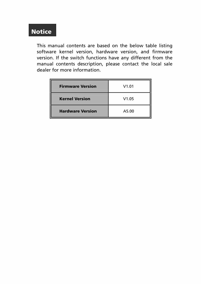
This manual contents are based on the below table listing software kernel version, hardware version, and firmware version. If the switch functions have any different from the manual contents description, please contact the local sale dealer for more information.
Firmware Version V1.01
Kernel Version V1.05
Hardware Version A5.00
Notice
24-Port PoE Injector User’s Manual Page 1/40
FCC Warning
This Equipment has been tested and found to comply with the limits for a Class-A
digital device, pursuant to Part 15 of the FCC rules. These limits are designed to
provide reasonable protection against harmful interference in a residential
installation. This equipment generates uses and can radiate radio frequency
energy and, if not installed and used in accordance with the instructions, may
cause harmful interference to radio communications. However, there is no
guarantee that interference will not occur in a particular installation. If this
equipment does cause harmful interference to radio or television reception, which
can be determined by turning the equipment off and on, the user is encouraged to
try to correct the interference by one or more of the following measures:
Reorient or relocate the receiving antenna.
Increase the separation between the equipment and receiver.
Connect the equipment into an outlet on a circuit different from that to which
the receiver is connected.
Consult the dealer or an experienced radio/TV technician for help.
CE Mark Warning
This is a Class-A product. In a domestic environment this product may cause radio
interference in which case the user may be required to take adequate measures.
MICROSENS GmbH & Co. KG · Kueferstraße 16 · 59067 Hamm / Germany · Tel. +49 23 81/94 52-0 · FAX -100 · www.microsens.com
24-Port PoE Injector User’s Manual Page 2/40
Content
FCC Warning................................................................................................................. 1
CE Mark Warning ......................................................................................................... 1
Content ................................................................................................................................ 2
Introduction......................................................................................................................... 4
Features ........................................................................................................................ 5
Package Contents......................................................................................................... 6
Hardware Description ......................................................................................................... 7
Physical Dimension....................................................................................................... 7
Front Panel ................................................................................................................... 7
LED Indicators............................................................................................................... 7
Rear Panel..................................................................................................................... 9
Power On...................................................................................................................... 9
Network Application.................................................................................................. 10
Console Management ....................................................................................................... 12
Connecting to the Console Port ................................................................................ 12
Login in the Console Interface .................................................................................. 13
CLI Management ........................................................................................................ 14
Web-Based Management.................................................................................................. 15
About Web-based Management............................................................................... 15
Preparing for Web Management .............................................................................. 15
System Login............................................................................................................... 16
Main menu ........................................................................................................................ 17
System......................................................................................................................... 17
System Information............................................................................................. 17
Console Port Information ................................................................................... 18
System IP Configuration ..................................................................................... 19
Security Manager ................................................................................................ 20
System Log........................................................................................................... 21
PoE .............................................................................................................................. 21
PoE Status ............................................................................................................ 22
Controller Temperature ...................................................................................... 23
PoE Power Manage............................................................................................. 23
PoE Port Configuration....................................................................................... 25
PoE Port Status .................................................................................................... 26
MISC Configuration.................................................................................................... 27
Power Status........................................................................................................ 27
SNTP Configuration ............................................................................................ 28
MICROSENS GmbH & Co. KG · Kueferstraße 16 · 59067 Hamm / Germany · Tel. +49 23 81/94 52-0 · FAX -100 · www.microsens.com
24-Port PoE Injector User’s Manual Page 3/40
SNMP Configuration ........................................................................................... 30
System Options ............................................................................................ 31
Community Strings ...................................................................................... 31
Trap Managers .................................................................................................... 31
Email Alert........................................................................................................... 32
IP Security ............................................................................................................ 33
TFTP Firmware Upgrade ............................................................................................ 34
Configuration Backup................................................................................................ 34
Save Configuration .................................................................................................... 35
Factory Default........................................................................................................... 35
System Reboot............................................................................................................ 36
Appendix A........................................................................................................................ 39
Console Port Pin Assignments ................................................................................... 39
RJ-45 pin assignment of non-802.3af standard PD with Mid-Spain POE INJECTOR
RJ-45 pin assignment ................................................................................................. 40
MICROSENS GmbH & Co. KG · Kueferstraße 16 · 59067 Hamm / Germany · Tel. +49 23 81/94 52-0 · FAX -100 · www.microsens.com
24-Port PoE Injector User’s Manual Page 4/40
Introduction Power-over-Ethernet (PoE) eliminates the need to run 100/240 VAC power to
other devices on a wired LAN. Using Power-over-Ethernet system installers need to
run only a single CAT5 Ethernet cable that carries both power and data to each
device. This allows greater flexibility in the locating of network devices and
significantly decreasing installation costs in many cases.
There are two system components in PoE – the Power Sourcing Equipment (PSE)
initiates the connection to the second component, the Powered Device (PD). The
current is transmitted over two of the four twisted pairs of wires in a Category-5
cable.
Power-over-Ethernet follows the IEEE 802.3af and is completely compatible with
existing Ethernet switches and networked devices. Because the Power Sourcing
Equipment (PSE) tests whether a networked device is PoE-capable, power is never
transmitted unless a Powered Device is at other end of the cable. It also continues
to monitor the channel. If the Powered Device does not draw a minimum current,
because it has been unplugged or physically turned off, the PSE shuts down the
power to that port. Optionally, the standard permits Powered Devices to signal to
the PSEs exactly how much power they need.
MICROSENS GmbH & Co. KG · Kueferstraße 16 · 59067 Hamm / Germany · Tel. +49 23 81/94 52-0 · FAX -100 · www.microsens.com
24-Port PoE Injector User’s Manual Page 5/40
Features
24port Power-over-Ethernet Injector with 1x10/100TX for system management
400W Fully Power support
Support 802.3af pre-standard PD
Support power feeding priority
Temperature monitoring
Power limit setting
TFTP firmware update
System log
Configuration up-load and down-load
SNMP / Web/Console/Telnet management
Circuit short protect
Confirms to IEEE802.3 10BASE-T, 802.3u 100BASE-TX and 802.3af
Power-over-Ethernet
Support Redundant Power
Simple Network Time Protocol (SNTP)
Simple Mail Transfer Protocol (SMTP)
DHCP Client support
SNMP Trap support
Management IP address security
Fan fail detect
Command line support
Power overloading protect
Fan detect
MICROSENS GmbH & Co. KG · Kueferstraße 16 · 59067 Hamm / Germany · Tel. +49 23 81/94 52-0 · FAX -100 · www.microsens.com
24-Port PoE Injector User’s Manual Page 6/40
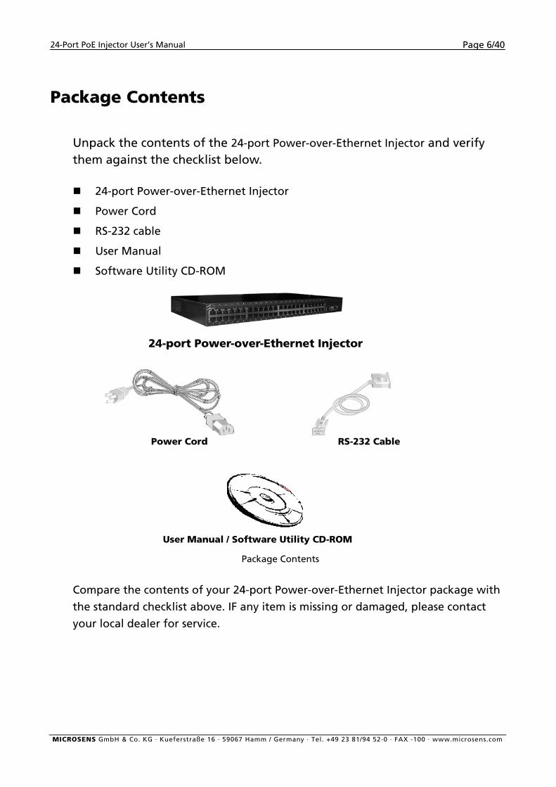
Package Contents
Unpack the contents of the 24-port Power-over-Ethernet Injector and verify them against the checklist below. 24-port Power-over-Ethernet Injector
Power Cord
RS-232 cable
User Manual
Software Utility CD-ROM
24-port Power-over-Ethernet Injector
Power Cord RS-232 Cable
User Manual / Software Utility CD-ROM
Package Contents
Compare the contents of your 24-port Power-over-Ethernet Injector package with
the standard checklist above. IF any item is missing or damaged, please contact
your local dealer for service.
MICROSENS GmbH & Co. KG · Kueferstraße 16 · 59067 Hamm / Germany · Tel. +49 23 81/94 52-0 · FAX -100 · www.microsens.com
24-Port PoE Injector User’s Manual Page 7/40
Hardware Description This Section mainly describes the hardware of the 24-port Power-over-Ethernet
Injector, and gives a physical and functional overview.
Physical Dimension
The 24-port Power-over-Ethernet Injector physical dimension is:
440mm x 225mm x 44mm (W x D x H)
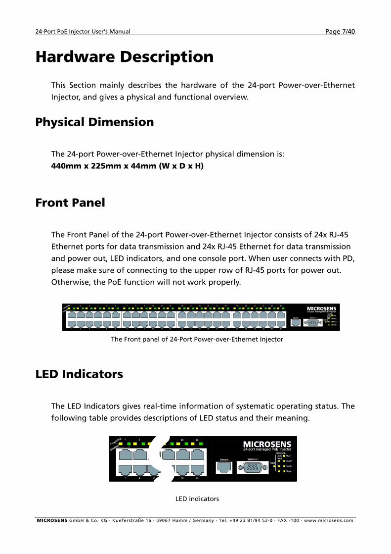
Front Panel
The Front Panel of the 24-port Power-over-Ethernet Injector consists of 24x RJ-45
Ethernet ports for data transmission and 24x RJ-45 Ethernet for data transmission
and power out, LED indicators, and one console port. When user connects with PD,
please make sure of connecting to the upper row of RJ-45 ports for power out.
Otherwise, the PoE function will not work properly.
The Front panel of 24-Port Power-over-Ethernet Injector
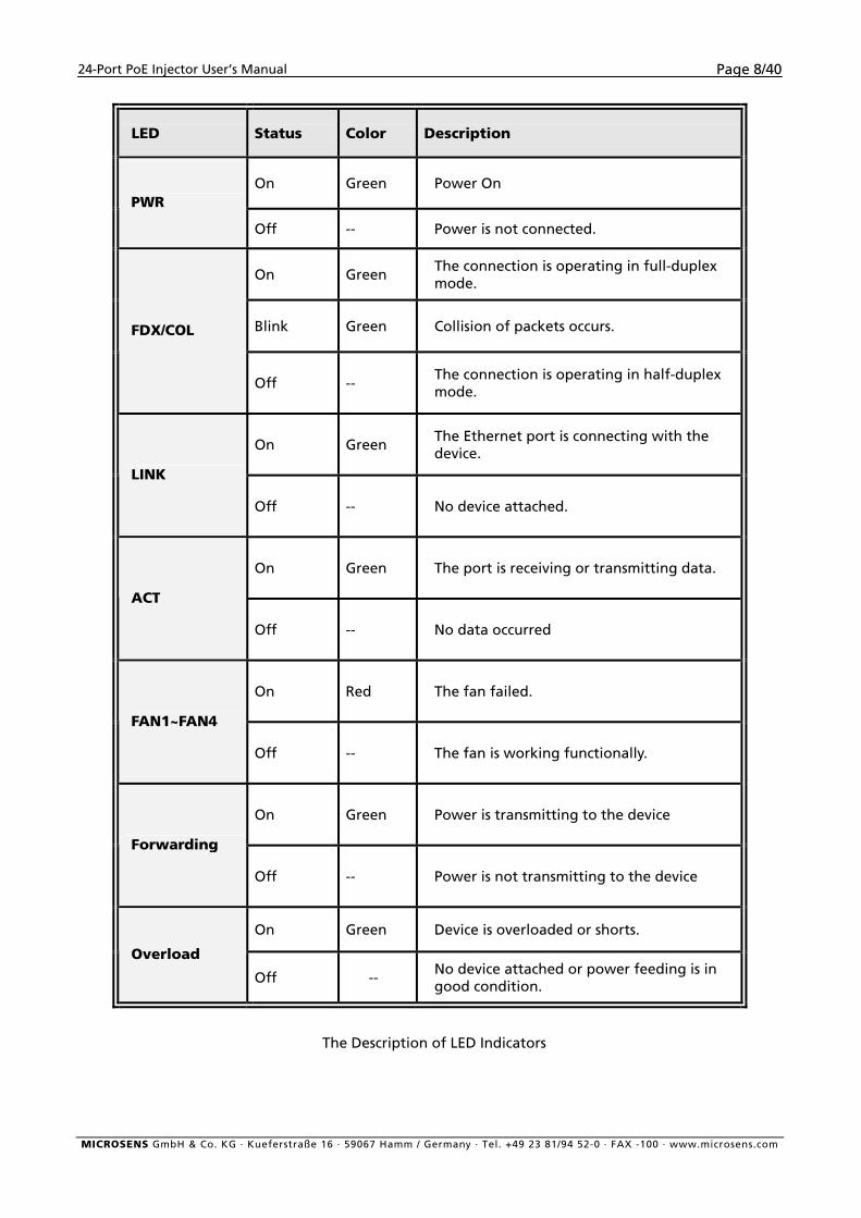
LED Indicators
The LED Indicators gives real-time information of systematic operating status. The
following table provides descriptions of LED status and their meaning.
LED indicators
MICROSENS GmbH & Co. KG · Kueferstraße 16 · 59067 Hamm / Germany · Tel. +49 23 81/94 52-0 · FAX -100 · www.microsens.com
24-Port PoE Injector User’s Manual Page 8/40
LED Status Color Description
On Green Power On PWR
Off -- Power is not connected.
On Green The connection is operating in full-duplex mode.
Blink Green Collision of packets occurs. FDX/COL
Off -- The connection is operating in half-duplex mode.
On Green The Ethernet port is connecting with the device.
LINK
Off -- No device attached.
On Green The port is receiving or transmitting data.
ACT
Off -- No data occurred
On Red The fan failed.
FAN1~FAN4
Off -- The fan is working functionally.
On Green Power is transmitting to the device
Forwarding
Off -- Power is not transmitting to the device
On Green Device is overloaded or shorts.
Overload
Off -- No device attached or power feeding is in good condition.
The Description of LED Indicators
MICROSENS GmbH & Co. KG · Kueferstraße 16 · 59067 Hamm / Germany · Tel. +49 23 81/94 52-0 · FAX -100 · www.microsens.com
24-Port PoE Injector User’s Manual Page 9/40
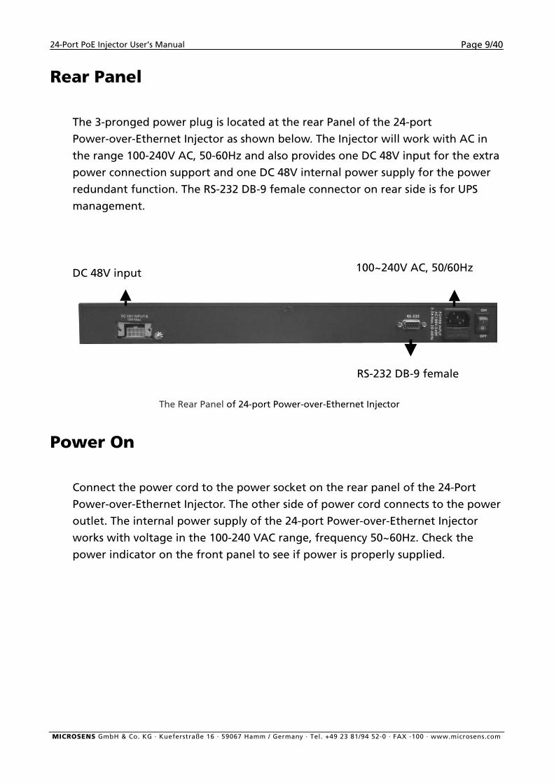
Rear Panel
The 3-pronged power plug is located at the rear Panel of the 24-port
Power-over-Ethernet Injector as shown below. The Injector will work with AC in
the range 100-240V AC, 50-60Hz and also provides one DC 48V input for the extra
power connection support and one DC 48V internal power supply for the power
redundant function. The RS-232 DB-9 female connector on rear side is for UPS
management.
100~240V AC, 50/60Hz DC 48V input
RS-232 DB-9 female
The Rear Panel of 24-port Power-over-Ethernet Injector
Power On
Connect the power cord to the power socket on the rear panel of the 24-Port
Power-over-Ethernet Injector. The other side of power cord connects to the power
outlet. The internal power supply of the 24-port Power-over-Ethernet Injector
works with voltage in the 100-240 VAC range, frequency 50~60Hz. Check the
power indicator on the front panel to see if power is properly supplied.
MICROSENS GmbH & Co. KG · Kueferstraße 16 · 59067 Hamm / Germany · Tel. +49 23 81/94 52-0 · FAX -100 · www.microsens.com
24-Port PoE Injector User’s Manual Page 10/40
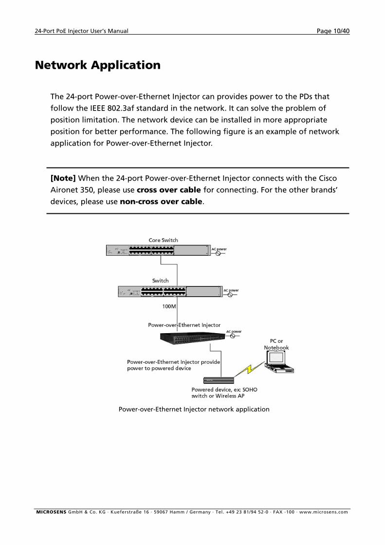
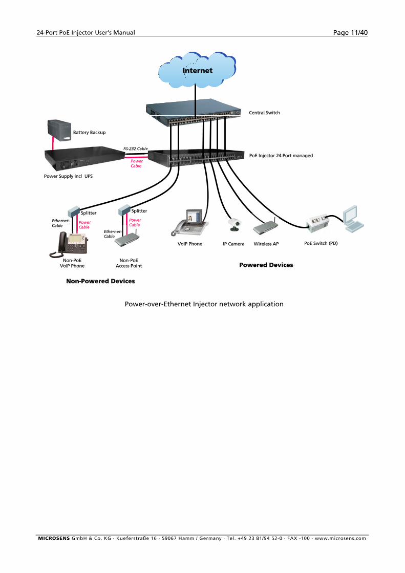
Network Application
The 24-port Power-over-Ethernet Injector can provides power to the PDs that
follow the IEEE 802.3af standard in the network. It can solve the problem of
position limitation. The network device can be installed in more appropriate
position for better performance. The following figure is an example of network
application for Power-over-Ethernet Injector.
[Note] When the 24-port Power-over-Ethernet Injector connects with the Cisco
Aironet 350, please use cross over cable for connecting. For the other brands’
devices, please use non-cross over cable.
Power-over-Ethernet Injector network application
MICROSENS GmbH & Co. KG · Kueferstraße 16 · 59067 Hamm / Germany · Tel. +49 23 81/94 52-0 · FAX -100 · www.microsens.com
24-Port PoE Injector User’s Manual Page 11/40
Power-over-Ethernet Injector network application
MICROSENS GmbH & Co. KG · Kueferstraße 16 · 59067 Hamm / Germany · Tel. +49 23 81/94 52-0 · FAX -100 · www.microsens.com
24-Port PoE Injector User’s Manual Page 12/40
Console Management
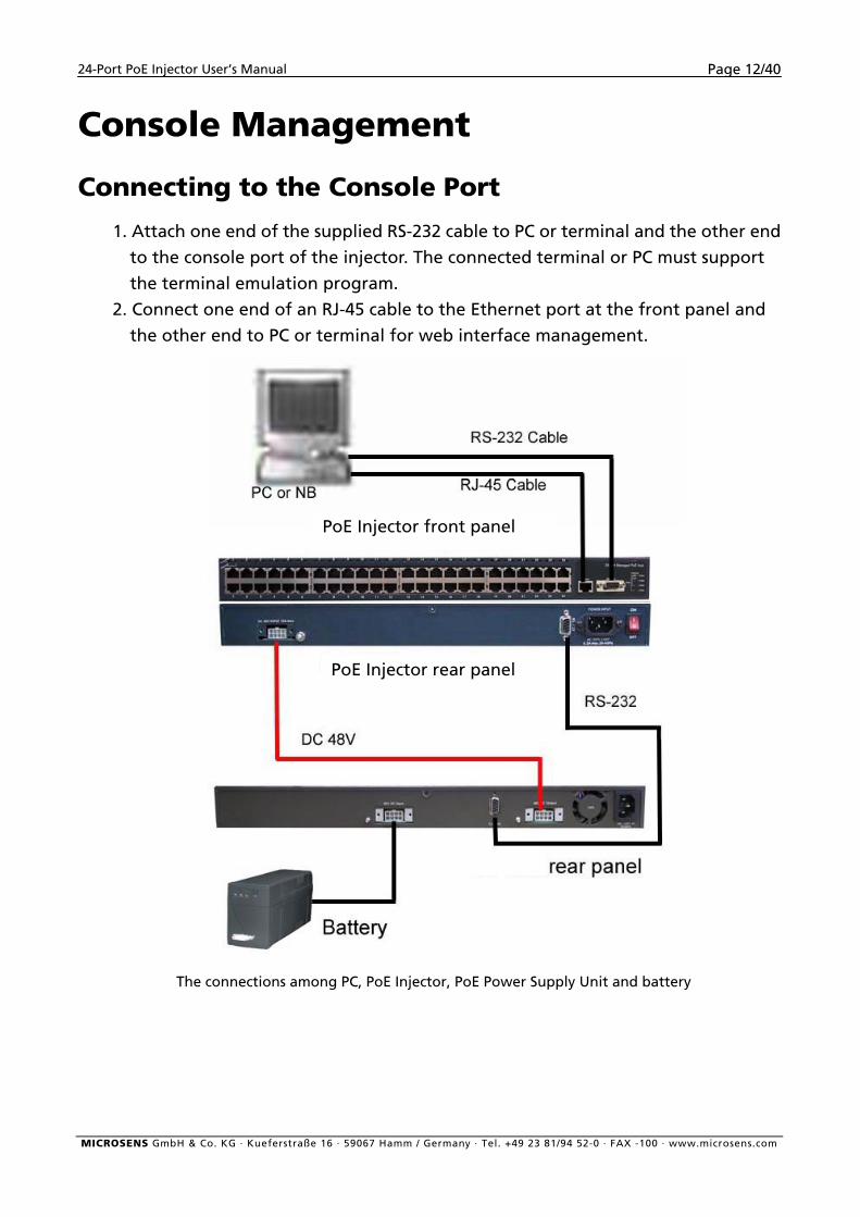
Connecting to the Console Port
1. Attach one end of the supplied RS-232 cable to PC or terminal and the other end
to the console port of the injector. The connected terminal or PC must support
the terminal emulation program.
2. Connect one end of an RJ-45 cable to the Ethernet port at the front panel and
the other end to PC or terminal for web interface management.
Label1
PoE Injector front panel
PoE Injector rear panel
The connections among PC, PoE Injector, PoE Power Supply Unit and battery
MICROSENS GmbH & Co. KG · Kueferstraße 16 · 59067 Hamm / Germany · Tel. +49 23 81/94 52-0 · FAX -100 · www.microsens.com
24-Port PoE Injector User’s Manual Page 13/40
Login in the Console Interface
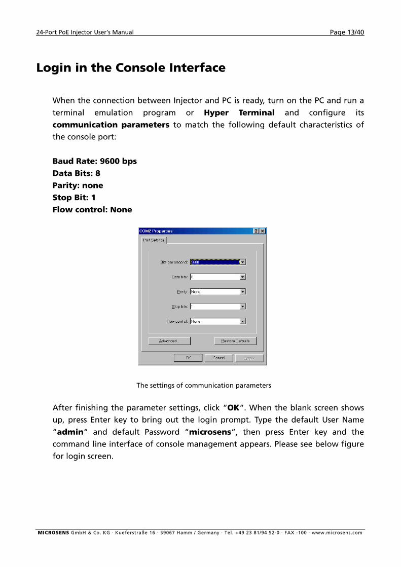
When the connection between Injector and PC is ready, turn on the PC and run a
terminal emulation program or Hyper Terminal and configure its
communication parameters to match the following default characteristics of
the console port:
Baud Rate: 9600 bps Data Bits: 8 Parity: none Stop Bit: 1 Flow control: None
The settings of communication parameters
After finishing the parameter settings, click “OK“. When the blank screen shows
up, press Enter key to bring out the login prompt. Type the default User Name
“admin“ and default Password “microsens“, then press Enter key and the
command line interface of console management appears. Please see below figure
for login screen.
MICROSENS GmbH & Co. KG · Kueferstraße 16 · 59067 Hamm / Germany · Tel. +49 23 81/94 52-0 · FAX -100 · www.microsens.com
24-Port PoE Injector User’s Manual Page 14/40
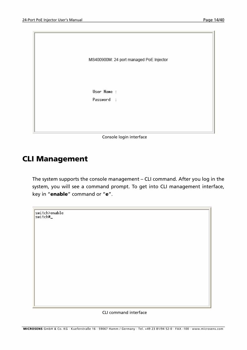
Console login interface
CLI Management
The system supports the console management – CLI command. After you log in the
system, you will see a command prompt. To get into CLI management interface,
key in “enable” command or “e”.
CLI command interface
MICROSENS GmbH & Co. KG · Kueferstraße 16 · 59067 Hamm / Germany · Tel. +49 23 81/94 52-0 · FAX -100 · www.microsens.com
24-Port PoE Injector User’s Manual Page 15/40
Web-Based Management
This section introduces the configuration and functions of the Web-Based
management.
About Web-based Management
On CPU board of the injector there is an embedded HTML web site residing in flash
memory, which offers advanced management features and allow users to manage
the injector from anywhere on the network through a standard browser such as
Microsoft Internet Explorer.
The Web-Based Management supports Internet Explorer 5.0. And, it is applied for
Java Applets for reducing network bandwidth consumption, enhance access speed
and present an easy viewing screen.
[NOTE] By default, IE5.0 or later version does not allow Java Applets to activate
sockets. In fact, the user has to explicitly modify the browser setting to enable Java
Applets to operate network ports.
Preparing for Web Management
Before using web management, install the Injector on the network and make sure
that any one of the PCs on the network can connect with the Injector through the
web browser. The Injector default of IP, subnet mask, user name and password are
as follows:
IP Address: 192.168.16.1
Subnet Mask: 255.255.255.0
Default Gateway: 192.168.16.254
User Name: admin
Password: microsens
MICROSENS GmbH & Co. KG · Kueferstraße 16 · 59067 Hamm / Germany · Tel. +49 23 81/94 52-0 · FAX -100 · www.microsens.com
24-Port PoE Injector User’s Manual Page 16/40
System Login
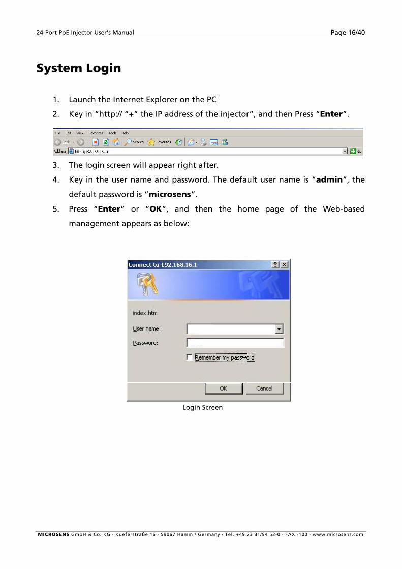
1. Launch the Internet Explorer on the PC
2. Key in “http:// “+” the IP address of the injector”, and then Press “Enter”.
3. The login screen will appear right after.
4. Key in the user name and password. The default user name is “admin”, the
default password is “microsens”.
5. Press “Enter” or ”OK”, and then the home page of the Web-based
management appears as below:
Login Screen
MICROSENS GmbH & Co. KG · Kueferstraße 16 · 59067 Hamm / Germany · Tel. +49 23 81/94 52-0 · FAX -100 · www.microsens.com
24-Port PoE Injector User’s Manual Page 17/40
Main menu
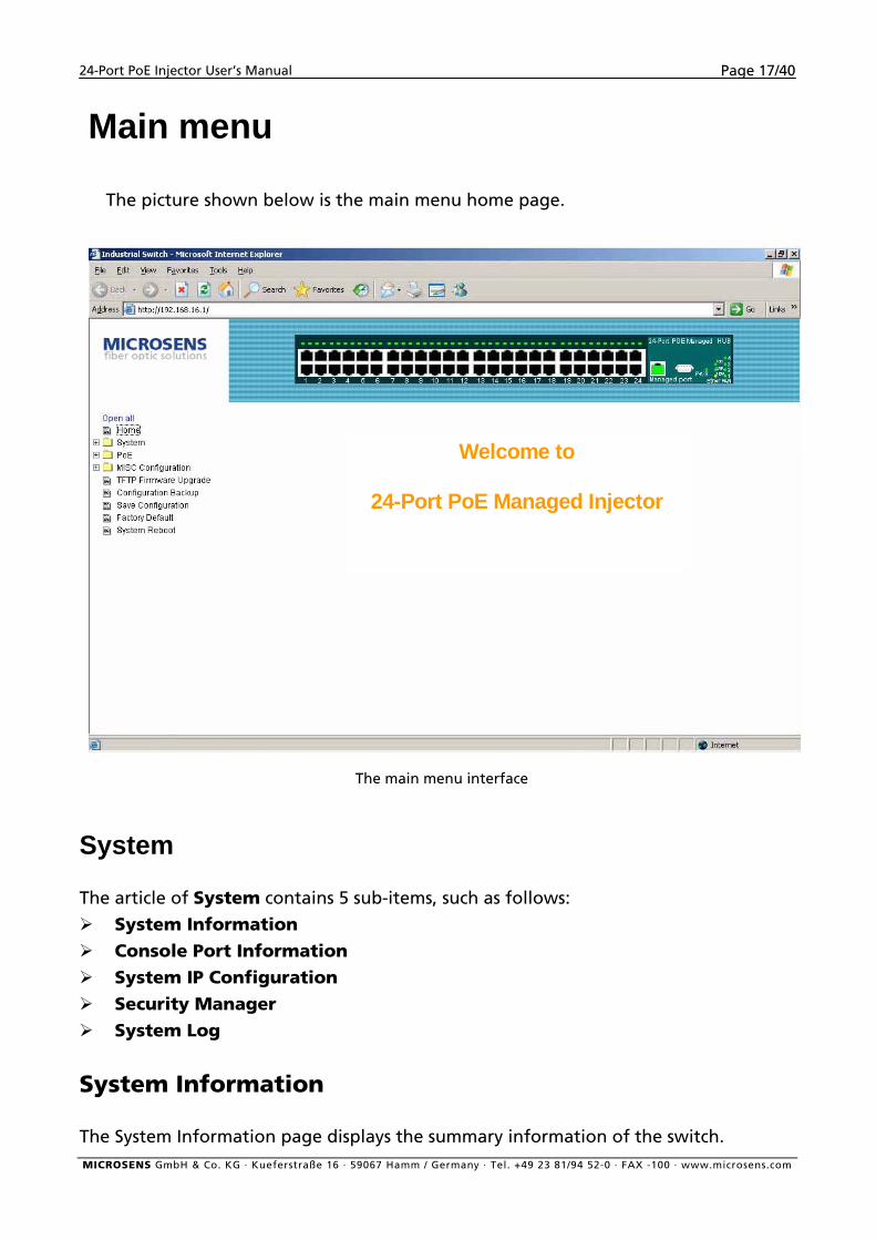
The picture shown below is the main menu home page.
Welcome to
24-Port PoE Managed Injector
The main menu interface
System
The article of System contains 5 sub-items, such as follows:
System Information Console Port Information
System IP Configuration
Security Manager
System Log
System Information
The System Information page displays the summary information of the switch. MICROSENS GmbH & Co. KG · Kueferstraße 16 · 59067 Hamm / Germany · Tel. +49 23 81/94 52-0 · FAX -100 · www.microsens.com
24-Port PoE Injector User’s Manual Page 18/40
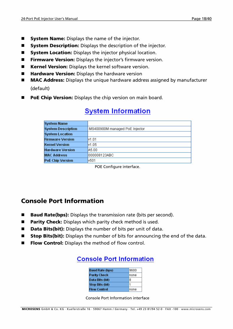
System Name: Displays the name of the injector.
System Description: Displays the description of the injector.
System Location: Displays the injector physical location. Firmware Version: Displays the injector’s firmware version.
Kernel Version: Displays the kernel software version.
Hardware Version: Displays the hardware version MAC Address: Displays the unique hardware address assigned by manufacturer
(default)
PoE Chip Version: Displays the chip version on main board.
POE Configure interface.
Console Port Information
Baud Rate(bps): Displays the transmission rate (bits per second).
Parity Check: Displays which parity check method is used.
Data Bits(bit): Displays the number of bits per unit of data.
Stop Bits(bit): Displays the number of bits for announcing the end of the data.
Flow Control: Displays the method of flow control.
Console Port Information interface
MICROSENS GmbH & Co. KG · Kueferstraße 16 · 59067 Hamm / Germany · Tel. +49 23 81/94 52-0 · FAX -100 · www.microsens.com
24-Port PoE Injector User’s Manual Page 19/40
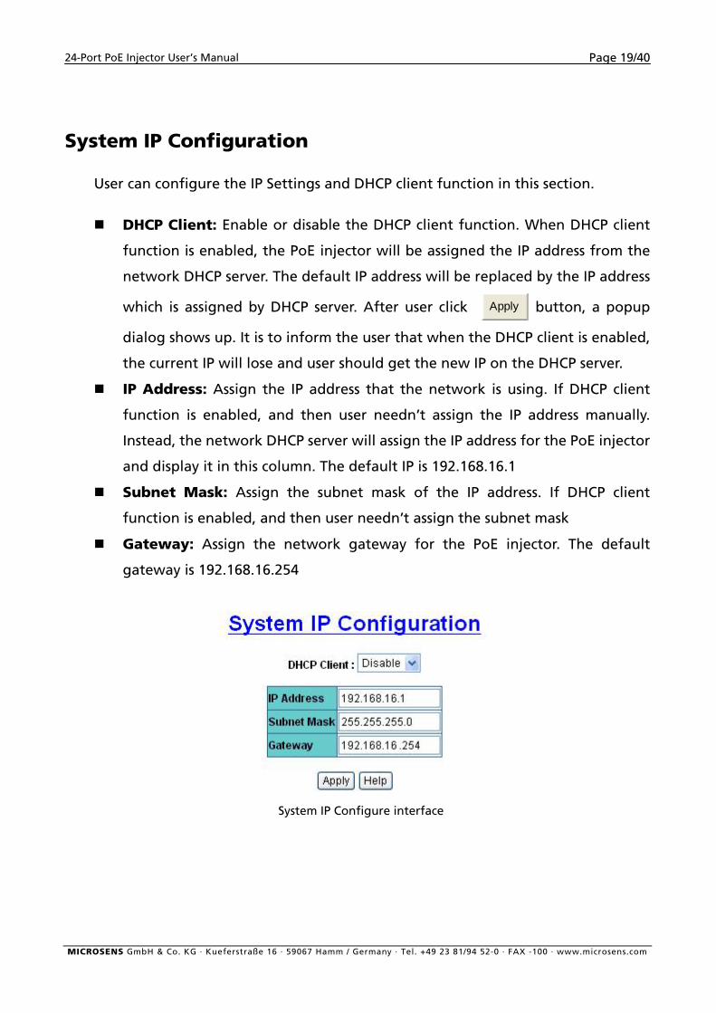
System IP Configuration
User can configure the IP Settings and DHCP client function in this section.
DHCP Client: Enable or disable the DHCP client function. When DHCP client
function is enabled, the PoE injector will be assigned the IP address from the
network DHCP server. The default IP address will be replaced by the IP address
which is assigned by DHCP server. After user click Apply button, a popup
dialog shows up. It is to inform the user that when the DHCP client is enabled,
the current IP will lose and user should get the new IP on the DHCP server.
IP Address: Assign the IP address that the network is using. If DHCP client
function is enabled, and then user needn’t assign the IP address manually.
Instead, the network DHCP server will assign the IP address for the PoE injector
and display it in this column. The default IP is 192.168.16.1
Subnet Mask: Assign the subnet mask of the IP address. If DHCP client
function is enabled, and then user needn’t assign the subnet mask
Gateway: Assign the network gateway for the PoE injector. The default
gateway is 192.168.16.254
System IP Configure interface
MICROSENS GmbH & Co. KG · Kueferstraße 16 · 59067 Hamm / Germany · Tel. +49 23 81/94 52-0 · FAX -100 · www.microsens.com
24-Port PoE Injector User’s Manual Page 20/40
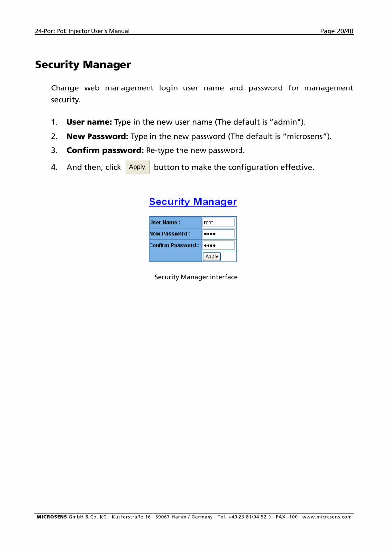
Security Manager
Change web management login user name and password for management
security.
1. User name: Type in the new user name (The default is “admin”).
2. New Password: Type in the new password (The default is “microsens”).
3. Confirm password: Re-type the new password.
4. And then, click Apply button to make the configuration effective.
Security Manager interface
MICROSENS GmbH & Co. KG · Kueferstraße 16 · 59067 Hamm / Germany · Tel. +49 23 81/94 52-0 · FAX -100 · www.microsens.com
24-Port PoE Injector User’s Manual Page 21/40
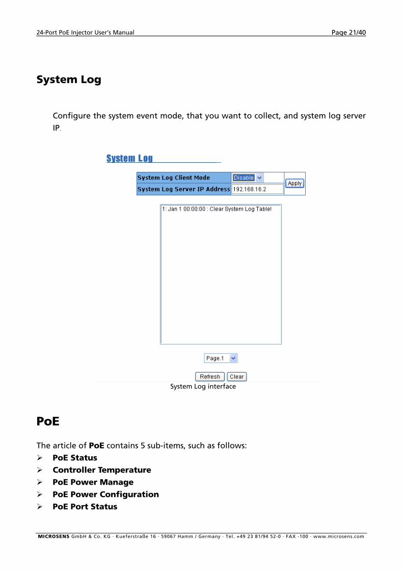
System Log
Configure the system event mode, that you want to collect, and system log server
IP.
System Log interface
PoE
The article of PoE contains 5 sub-items, such as follows:
PoE Status Controller Temperature
PoE Power Manage
PoE Power Configuration
PoE Port Status
MICROSENS GmbH & Co. KG · Kueferstraße 16 · 59067 Hamm / Germany · Tel. +49 23 81/94 52-0 · FAX -100 · www.microsens.com
24-Port PoE Injector User’s Manual Page 22/40
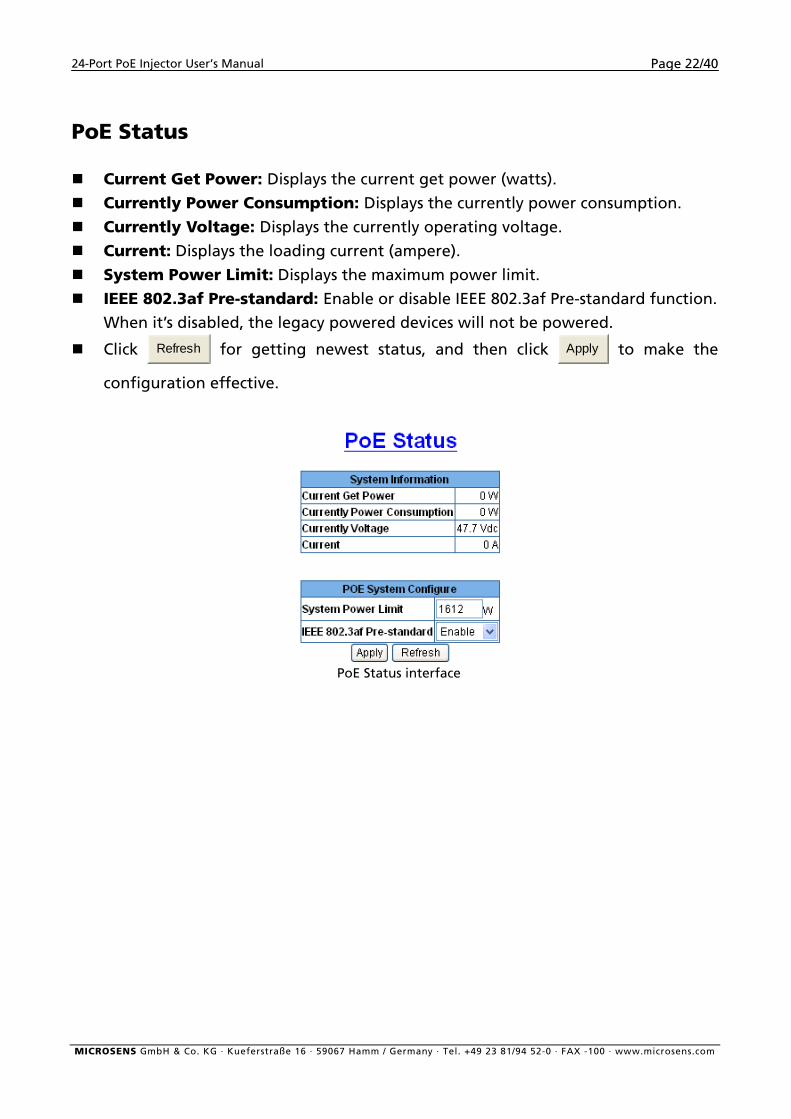
PoE Status
Current Get Power: Displays the current get power (watts).
Currently Power Consumption: Displays the currently power consumption. Currently Voltage: Displays the currently operating voltage.
Current: Displays the loading current (ampere).
System Power Limit: Displays the maximum power limit.
IEEE 802.3af Pre-standard: Enable or disable IEEE 802.3af Pre-standard function.
When it’s disabled, the legacy powered devices will not be powered.
Click Refresh for getting newest status, and then click Apply to make the
configuration effective.
PoE Status interface
MICROSENS GmbH & Co. KG · Kueferstraße 16 · 59067 Hamm / Germany · Tel. +49 23 81/94 52-0 · FAX -100 · www.microsens.com
24-Port PoE Injector User’s Manual Page 23/40
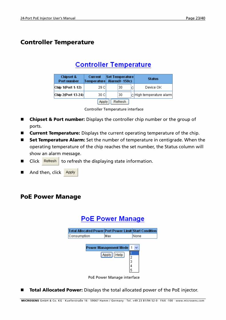
Controller Temperature
Controller Temperature interface
Chipset & Port number: Displays the controller chip number or the group of
ports.
Current Temperature: Displays the current operating temperature of the chip. Set Temperature Alarm: Set the number of temperature in centigrade. When the
operating temperature of the chip reaches the set number, the Status column will
show an alarm message.
Click Refresh to refresh the displaying state information.
And then, click Apply
PoE Power Manage
PoE Power Manage interface
Total Allocated Power: Displays the total allocated power of the PoE injector.
MICROSENS GmbH & Co. KG · Kueferstraße 16 · 59067 Hamm / Germany · Tel. +49 23 81/94 52-0 · FAX -100 · www.microsens.com
24-Port PoE Injector User’s Manual Page 24/40
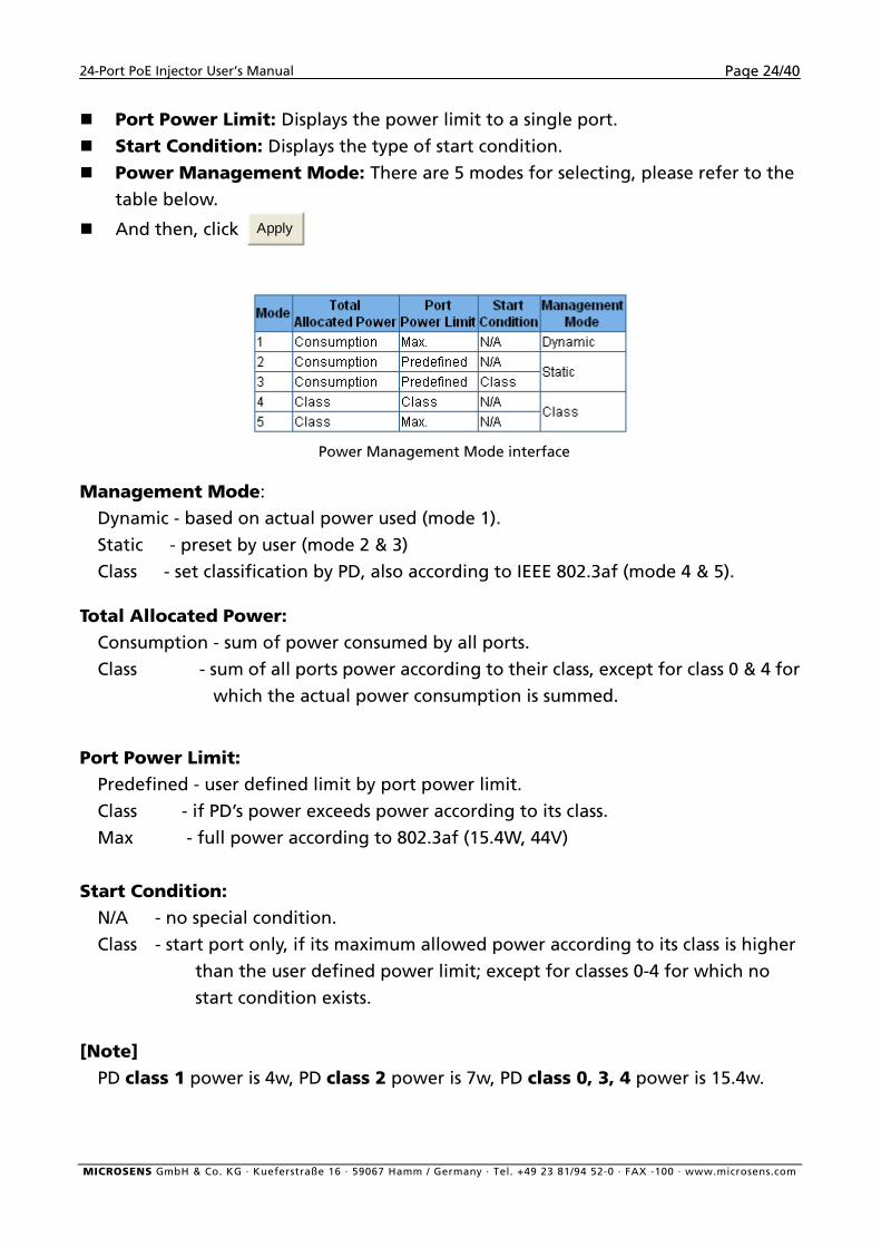
Port Power Limit: Displays the power limit to a single port.
Start Condition: Displays the type of start condition.
Power Management Mode: There are 5 modes for selecting, please refer to the
table below.
And then, click Apply
Power Management Mode interface
Management Mode:
Dynamic - based on actual power used (mode 1).
Static - preset by user (mode 2 & 3)
Class - set classification by PD, also according to IEEE 802.3af (mode 4 & 5).
Total Allocated Power: Consumption - sum of power consumed by all ports.
Class - sum of all ports power according to their class, except for class 0 & 4 for
which the actual power consumption is summed.
Port Power Limit: Predefined - user defined limit by port power limit.
Class - if PD’s power exceeds power according to its class.
Max - full power according to 802.3af (15.4W, 44V)
Start Condition: N/A - no special condition.
Class - start port only, if its maximum allowed power according to its class is higher
than the user defined power limit; except for classes 0-4 for which no
start condition exists.
[Note] PD class 1 power is 4w, PD class 2 power is 7w, PD class 0, 3, 4 power is 15.4w.
MICROSENS GmbH & Co. KG · Kueferstraße 16 · 59067 Hamm / Germany · Tel. +49 23 81/94 52-0 · FAX -100 · www.microsens.com
24-Port PoE Injector User’s Manual Page 25/40
PoE Port Configuration
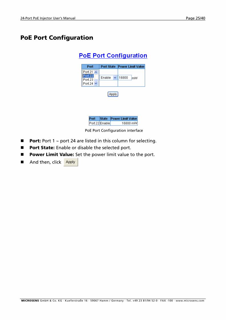
PoE Port Configuration interface
Port: Port 1 ~ port 24 are listed in this column for selecting.
Port State: Enable or disable the selected port.
Power Limit Value: Set the power limit value to the port.
And then, click Apply
MICROSENS GmbH & Co. KG · Kueferstraße 16 · 59067 Hamm / Germany · Tel. +49 23 81/94 52-0 · FAX -100 · www.microsens.com
24-Port PoE Injector User’s Manual Page 26/40
PoE Port Status
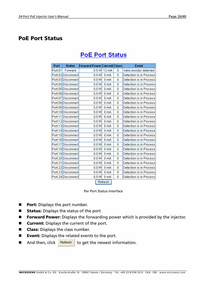
Per Port Status interface
Port: Displays the port number.
Status: Displays the status of the port.
Forward Power: Displays the forwarding power which is provided by the injector.
Current: Displays the current of the port.
Class: Displays the class number.
Event: Displays the related events to the port.
And then, click Refresh to get the newest information.
MICROSENS GmbH & Co. KG · Kueferstraße 16 · 59067 Hamm / Germany · Tel. +49 23 81/94 52-0 · FAX -100 · www.microsens.com
24-Port PoE Injector User’s Manual Page 27/40
MISC Configuration
The article of MISC Configuration contains 5 sub-items:
Power Status SNTP Configuration SNMP Configuration Email Alert IP Security
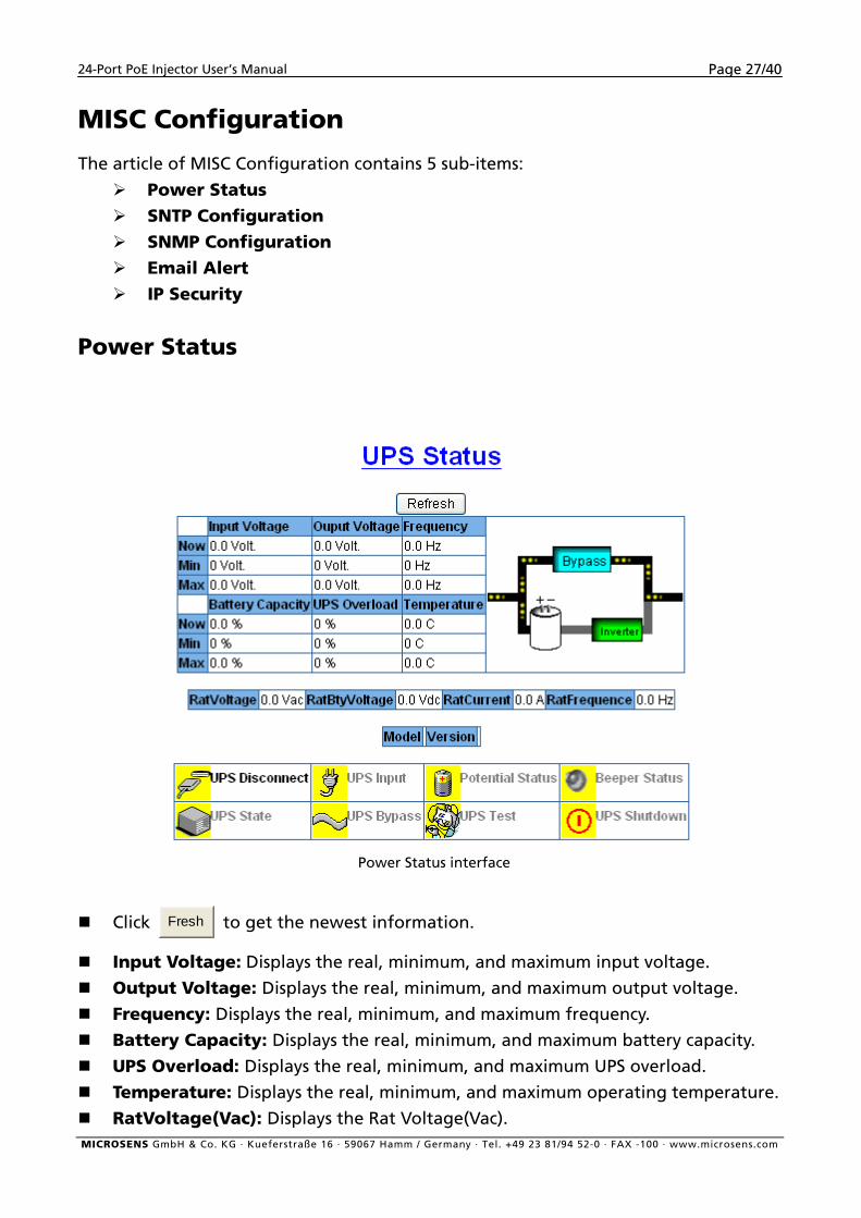
Power Status
Power Status interface
Click Fresh to get the newest information.
Input Voltage: Displays the real, minimum, and maximum input voltage.
Output Voltage: Displays the real, minimum, and maximum output voltage.
Frequency: Displays the real, minimum, and maximum frequency.
Battery Capacity: Displays the real, minimum, and maximum battery capacity.
UPS Overload: Displays the real, minimum, and maximum UPS overload.
Temperature: Displays the real, minimum, and maximum operating temperature.
RatVoltage(Vac): Displays the Rat Voltage(Vac). MICROSENS GmbH & Co. KG · Kueferstraße 16 · 59067 Hamm / Germany · Tel. +49 23 81/94 52-0 · FAX -100 · www.microsens.com
24-Port PoE Injector User’s Manual Page 28/40
RatVoltage(Vdc): Displays the Rat Voltage(Vdc).
RatCurrent: Displays the RatCurrent.
RatFrequence: Displays the RatFrequence.
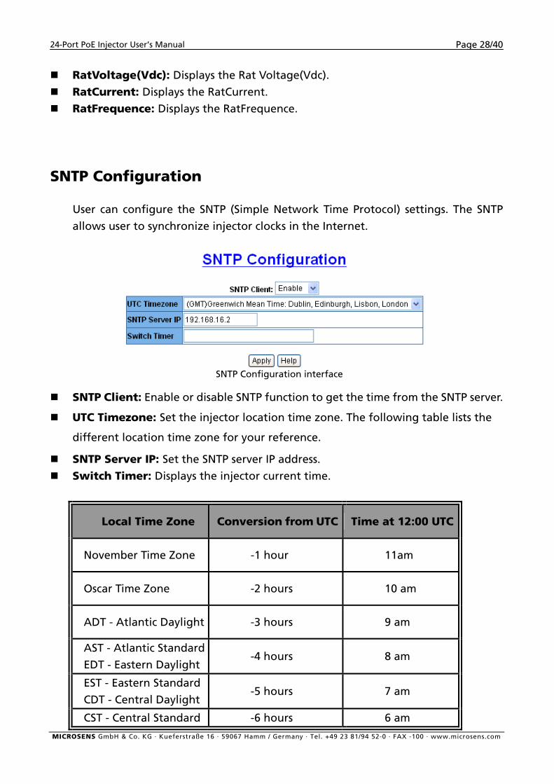
SNTP Configuration
User can configure the SNTP (Simple Network Time Protocol) settings. The SNTP
allows user to synchronize injector clocks in the Internet.
SNTP Configuration interface
SNTP Client: Enable or disable SNTP function to get the time from the SNTP server.
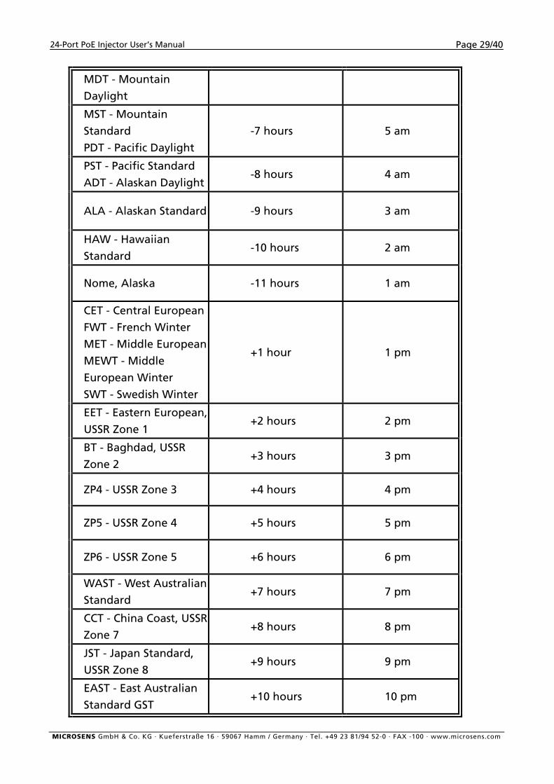
UTC Timezone: Set the injector location time zone. The following table lists the
different location time zone for your reference.
SNTP Server IP: Set the SNTP server IP address.
Switch Timer: Displays the injector current time.
Local Time Zone Conversion from UTC Time at 12:00 UTC
November Time Zone -1 hour 11am
Oscar Time Zone -2 hours 10 am
ADT - Atlantic Daylight -3 hours 9 am
AST - Atlantic Standard
EDT - Eastern Daylight -4 hours 8 am
EST - Eastern Standard
CDT - Central Daylight -5 hours 7 am
CST - Central Standard -6 hours 6 am MICROSENS GmbH & Co. KG · Kueferstraße 16 · 59067 Hamm / Germany · Tel. +49 23 81/94 52-0 · FAX -100 · www.microsens.com
24-Port PoE Injector User’s Manual Page 29/40
MDT - Mountain
Daylight MST - Mountain
Standard
PDT - Pacific Daylight -7 hours 5 am
PST - Pacific Standard
ADT - Alaskan Daylight -8 hours 4 am
ALA - Alaskan Standard -9 hours 3 am
HAW - Hawaiian
Standard -10 hours 2 am
Nome, Alaska -11 hours 1 am
CET - Central European
FWT - French Winter
MET - Middle European
MEWT - Middle
European Winter
SWT - Swedish Winter
+1 hour 1 pm
EET - Eastern European,
USSR Zone 1 +2 hours 2 pm
BT - Baghdad, USSR
Zone 2 +3 hours 3 pm
ZP4 - USSR Zone 3 +4 hours 4 pm
ZP5 - USSR Zone 4 +5 hours 5 pm
ZP6 - USSR Zone 5 +6 hours 6 pm
WAST - West Australian
Standard +7 hours 7 pm
CCT - China Coast, USSR
Zone 7 +8 hours 8 pm
JST - Japan Standard,
USSR Zone 8 +9 hours 9 pm
EAST - East Australian
Standard GST +10 hours 10 pm
MICROSENS GmbH & Co. KG · Kueferstraße 16 · 59067 Hamm / Germany · Tel. +49 23 81/94 52-0 · FAX -100 · www.microsens.com
24-Port PoE Injector User’s Manual Page 30/40
Guam Standard, USSR
Zone 9 IDLE - International
Date Line
NZST - New Zealand
Standard
NZT - New Zealand
+12 hours Midnight
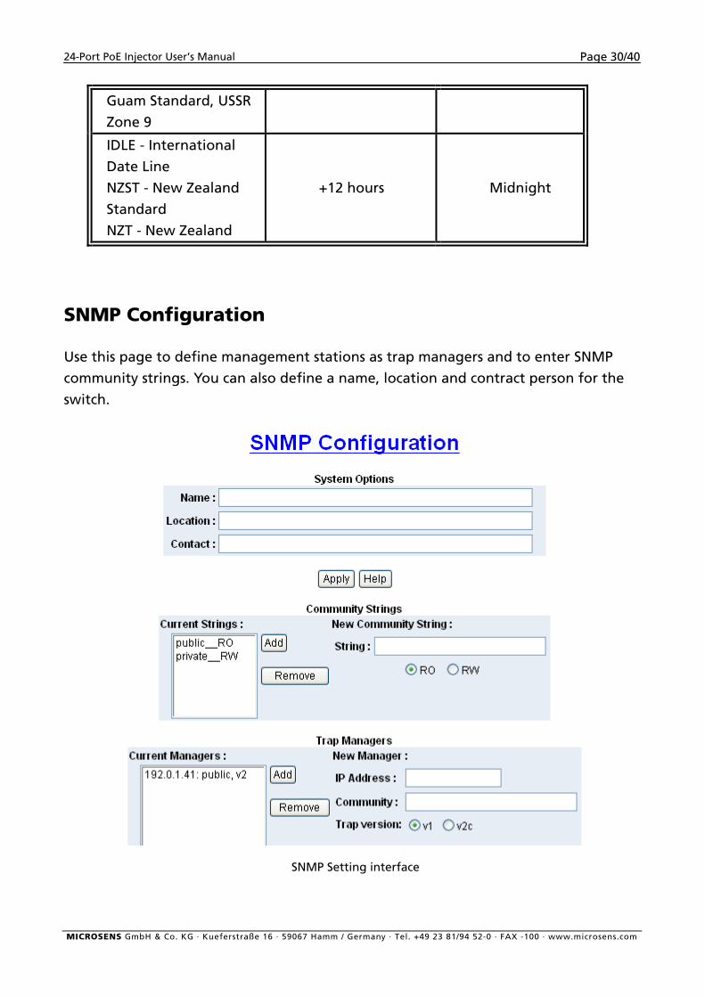
SNMP Configuration
Use this page to define management stations as trap managers and to enter SNMP
community strings. You can also define a name, location and contract person for the
switch.
SNMP Setting interface
MICROSENS GmbH & Co. KG · Kueferstraße 16 · 59067 Hamm / Germany · Tel. +49 23 81/94 52-0 · FAX -100 · www.microsens.com
24-Port PoE Injector User’s Manual Page 31/40
System Options
Enter the following information about the injector, as needed:
Name: Enter a name to be used for the injector.
Location: Enter the location of the PoE injector
Contact: Enter the name of contact person or organization.
Community Strings
Community strings serve as password and can be entered as one of the following:
Current Strings: User can remove the current strings or add new community
strings.
New Community Strings: Fill the column with name of string. Click Add .
To remove the community string, select the community string that you have
defined and click Remove . You cannot remove the default community string set.
RO: Read only. Enables requests accompanied by this string to display MIB-object
information.
RW: Read/write. Enables requests accompanied by this string to display MIB-object
information and to set MIB objects.
Trap Managers
A trap manager is a management station that receives traps. The management
station then generates alerts based on the received traps. If no trap manager is
defined, no traps will be issued. Create a trap manager by entering the IP address
of the station, a community string, and selects the SNMP version.
IP Address: Enter the IP address of trap manager.
Community: Enter the community string.
Trap version: Select the SNMP trap version type – v1 or v2c
MICROSENS GmbH & Co. KG · Kueferstraße 16 · 59067 Hamm / Germany · Tel. +49 23 81/94 52-0 · FAX -100 · www.microsens.com
24-Port PoE Injector User’s Manual Page 32/40
Email Alert
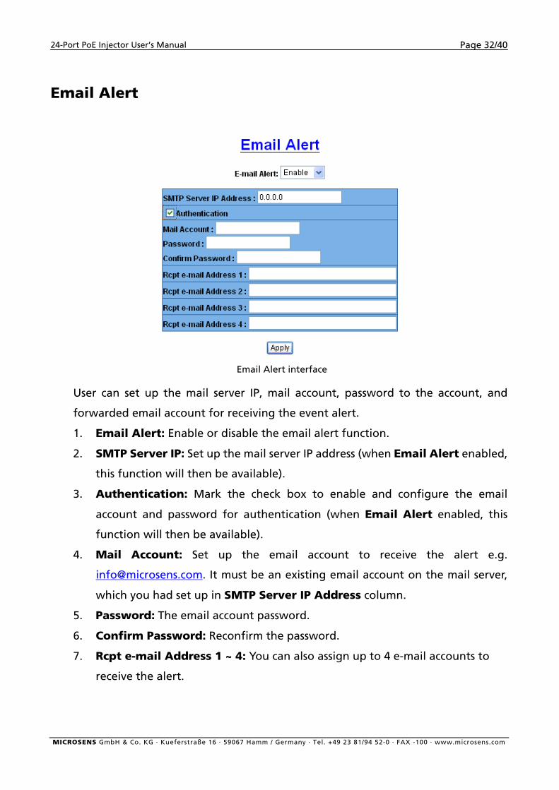
Email Alert interface
User can set up the mail server IP, mail account, password to the account, and
forwarded email account for receiving the event alert.
1. Email Alert: Enable or disable the email alert function.
2. SMTP Server IP: Set up the mail server IP address (when Email Alert enabled,
this function will then be available).
3. Authentication: Mark the check box to enable and configure the email
account and password for authentication (when Email Alert enabled, this
function will then be available).
4. Mail Account: Set up the email account to receive the alert e.g.
[email protected]. It must be an existing email account on the mail server,
which you had set up in SMTP Server IP Address column.
5. Password: The email account password.
6. Confirm Password: Reconfirm the password.
7. Rcpt e-mail Address 1 ~ 4: You can also assign up to 4 e-mail accounts to
receive the alert.
MICROSENS GmbH & Co. KG · Kueferstraße 16 · 59067 Hamm / Germany · Tel. +49 23 81/94 52-0 · FAX -100 · www.microsens.com
24-Port PoE Injector User’s Manual Page 33/40
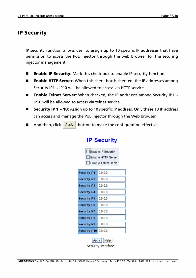
IP Security
IP security function allows user to assign up to 10 specific IP addresses that have
permission to access the PoE Injector through the web browser for the securing
injector management.
Enable IP Security: Mark this check box to enable IP security function.
Enable HTTP Server: When this check box is checked, the IP addresses among
Security IP1 ~ IP10 will be allowed to access via HTTP service.
Enable Telnet Server: When checked, the IP addresses among Security IP1 ~
IP10 will be allowed to access via telnet service.
Security IP 1 ~ 10: Assign up to 10 specific IP address. Only these 10 IP address
can access and manage the PoE injector through the Web browser
And then, click Apply button to make the configuration effective.
IP Security interface
MICROSENS GmbH & Co. KG · Kueferstraße 16 · 59067 Hamm / Germany · Tel. +49 23 81/94 52-0 · FAX -100 · www.microsens.com
24-Port PoE Injector User’s Manual Page 34/40
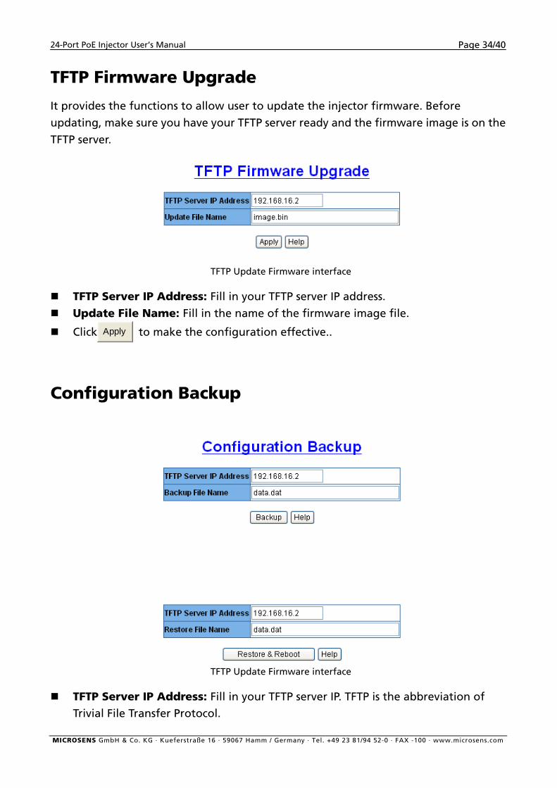
TFTP Firmware Upgrade
It provides the functions to allow user to update the injector firmware. Before
updating, make sure you have your TFTP server ready and the firmware image is on the
TFTP server.
TFTP Update Firmware interface
TFTP Server IP Address: Fill in your TFTP server IP address.
Update File Name: Fill in the name of the firmware image file.
Click Apply to make the configuration effective..
Configuration Backup
TFTP Update Firmware interface
TFTP Server IP Address: Fill in your TFTP server IP. TFTP is the abbreviation of
Trivial File Transfer Protocol.
MICROSENS GmbH & Co. KG · Kueferstraße 16 · 59067 Hamm / Germany · Tel. +49 23 81/94 52-0 · FAX -100 · www.microsens.com
24-Port PoE Injector User’s Manual Page 35/40
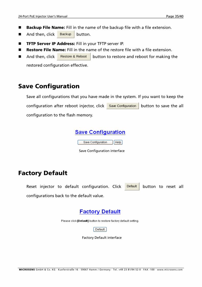
Backup File Name: Fill in the name of the backup file with a file extension.
And then, click Backup button.
TFTP Server IP Address: Fill in your TFTP server IP.
Restore File Name: Fill in the name of the restore file with a file extension.
And then, click Restore & Reboot button to restore and reboot for making the
restored configuration effective.
Save Configuration
Save all configurations that you have made in the system. If you want to keep the
configuration after reboot injector, click Save Configuration button to save the all
configuration to the flash memory.
Save Configuration interface
Factory Default
Reset injector to default configuration. Click Default button to reset all
configurations back to the default value.
Factory Default interface
MICROSENS GmbH & Co. KG · Kueferstraße 16 · 59067 Hamm / Germany · Tel. +49 23 81/94 52-0 · FAX -100 · www.microsens.com
24-Port PoE Injector User’s Manual Page 36/40
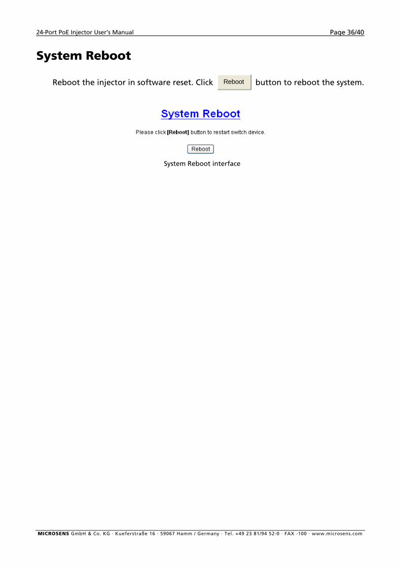
System Reboot
Reboot the injector in software reset. Click Reboot button to reboot the system.
System Reboot interface
MICROSENS GmbH & Co. KG · Kueferstraße 16 · 59067 Hamm / Germany · Tel. +49 23 81/94 52-0 · FAX -100 · www.microsens.com
24-Port PoE Injector User’s Manual Page 37/40
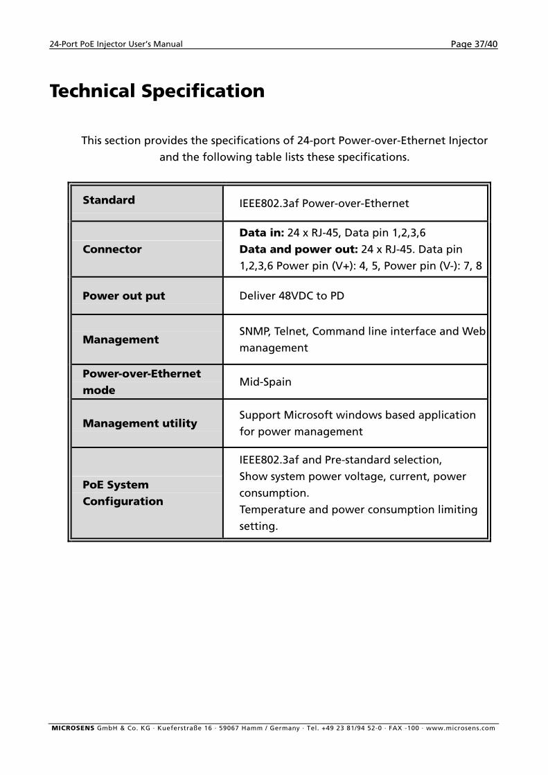
Technical Specification
This section provides the specifications of 24-port Power-over-Ethernet Injector
and the following table lists these specifications.
Standard IEEE802.3af Power-over-Ethernet
Connector Data in: 24 x RJ-45, Data pin 1,2,3,6
Data and power out: 24 x RJ-45. Data pin
1,2,3,6 Power pin (V+): 4, 5, Power pin (V-): 7, 8
Power out put Deliver 48VDC to PD
Management SNMP, Telnet, Command line interface and Web
management
Power-over-Ethernet mode
Mid-Spain
Management utility Support Microsoft windows based application
for power management
PoE System Configuration
IEEE802.3af and Pre-standard selection,
Show system power voltage, current, power
consumption.
Temperature and power consumption limiting
setting.
MICROSENS GmbH & Co. KG · Kueferstraße 16 · 59067 Hamm / Germany · Tel. +49 23 81/94 52-0 · FAX -100 · www.microsens.com
24-Port PoE Injector User’s Manual Page 38/40
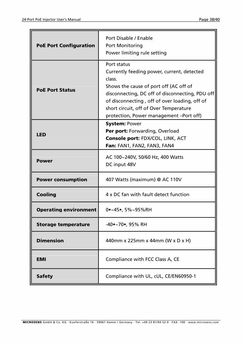
PoE Port Configuration
Port Disable / Enable
Port Monitoring
Power limiting rule setting
PoE Port Status
Port status
Currently feeding power, current, detected
class.
Shows the cause of port off (AC off of
disconnecting, DC off of disconnecting, PDU off
of disconnecting , off of over loading, off of
short circuit, off of Over Temperature
protection, Power management –Port off)
LED
System: Power
Per port: Forwarding, Overload
Console port: FDX/COL, LINK, ACT Fan: FAN1, FAN2, FAN3, FAN4
Power AC 100~240V, 50/60 Hz, 400 Watts
DC input 48V
Power consumption 407 Watts (maximum) @ AC 110V
Cooling 4 x DC fan with fault detect function
Operating environment 0•~45•, 5%~95%RH
Storage temperature -40•~70•, 95% RH
Dimension 440mm x 225mm x 44mm (W x D x H)
EMI Compliance with FCC Class A, CE
Safety Compliance with UL, cUL, CE/EN60950-1
MICROSENS GmbH & Co. KG · Kueferstraße 16 · 59067 Hamm / Germany · Tel. +49 23 81/94 52-0 · FAX -100 · www.microsens.com
24-Port PoE Injector User’s Manual Page 39/40
Appendix A
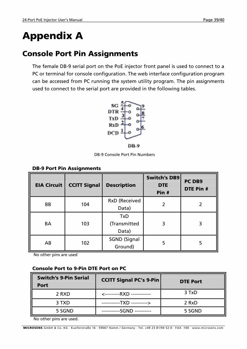
Console Port Pin Assignments
The female DB-9 serial port on the PoE injector front panel is used to connect to a
PC or terminal for console configuration. The web interface configuration program
can be accessed from PC running the system utility program. The pin assignments
used to connect to the serial port are provided in the following tables.
DB-9 Console Port Pin Numbers
DB-9 Port Pin Assignments
EIA Circuit CCITT Signal Description Switch’s DB9
DTE Pin #
PC DB9 DTE Pin #
BB 104 RxD (Received
Data) 2 2
BA 103
TxD
(Transmitted
Data)
3 3
AB 102 SGND (Signal
Ground) 5 5
No other pins are used
Console Port to 9-Pin DTE Port on PC
Switch’s 9-Pin Serial Port
CCITT Signal PC’s 9-Pin DTE Port
2 RXD <---------RXD ------------ 3 TxD
3 TXD -----------TXD ----------> 2 RxD
5 SGND -----------SGND ---------- 5 SGND
No other pins are used.
MICROSENS GmbH & Co. KG · Kueferstraße 16 · 59067 Hamm / Germany · Tel. +49 23 81/94 52-0 · FAX -100 · www.microsens.com
24-Port PoE Injector User’s Manual Page 40/40
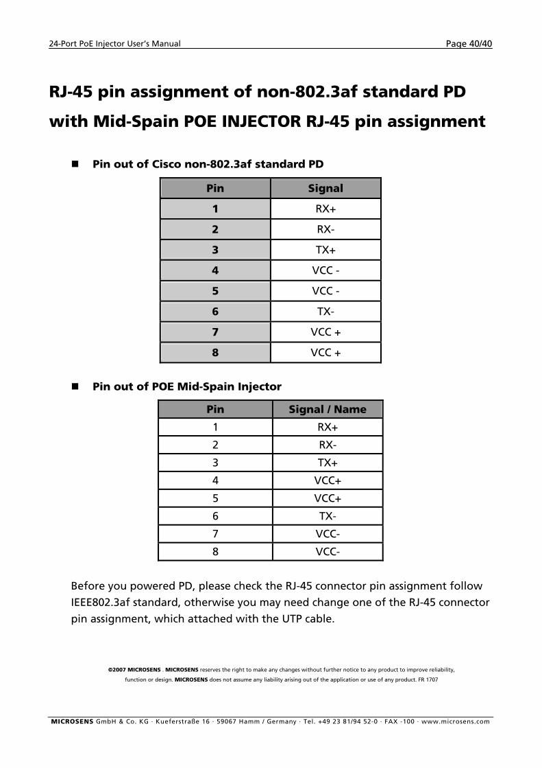
RJ-45 pin assignment of non-802.3af standard PD
with Mid-Spain POE INJECTOR RJ-45 pin assignment
Pin out of Cisco non-802.3af standard PD
Pin Signal
1 RX+
2 RX-
3 TX+
4 VCC -
5 VCC -
6 TX-
7 VCC +
8 VCC +
Pin out of POE Mid-Spain Injector
Pin Signal / Name
1 RX+
2 RX-
3 TX+
4 VCC+
5 VCC+
6 TX-
7 VCC-
8 VCC-
Before you powered PD, please check the RJ-45 connector pin assignment follow
IEEE802.3af standard, otherwise you may need change one of the RJ-45 connector
pin assignment, which attached with the UTP cable.
©2007 MICROSENS . MICROSENS reserves the right to make any changes without further notice to any product to improve reliability,
function or design. MICROSENS does not assume any liability arising out of the application or use of any product. FR 1707
MICROSENS GmbH & Co. KG · Kueferstraße 16 · 59067 Hamm / Germany · Tel. +49 23 81/94 52-0 · FAX -100 · www.microsens.com