micro/nanotechnology for picosatellites
TRANSCRIPT

1© 2008 The Aerospace Corporation
Micro/Nanotechnology for Picosatellites
Siegfried W. Janson
August 13, 2008
SSC08-VII-6

2
Small Satellite Classification
Microsatellite: 10-to-100 kgNanosatellite: 1-to-10 kgPicosatellite: 0.1-to-1 kgFemtosatellite: 10-to-100 gAttosatellite: 1-to-10 g
Zeptosatellite: 0.1-to-1 g
Yoctosatellite: 10-to-100 mgXennosatellite: 1-to-10 mg
On-Orbit
Possible
Way Out

3
Passive SatellitesActive Satellites
PicosatelliteEra
Picosatellite Flight History
ERS-5, -6
Calsphere-1 Calsphere-3, -4, -5,2-meter Mylar balloon ODERACS
spheres
OPALpicosatellites
Cube-Sats

4
The Aerospace Corporation Picosatellites• Two on OPAL
- Ejected February 6, 2000• Two on MightySat II.1
- Ejected September 7, 2001• 65-mW transmitter
- 150’ dia. receive antenna• MEMS payload
-RF Switches by Rockwell Scientific• 10-W-hr primary battery
• Tethered together- 100-foot long tether- Gold dipoles for increased RCS
• Smallest active satellites ever flown- 1” x 3” x 4”- 275-gram mass
Photo by The Aerospace Corporation
5
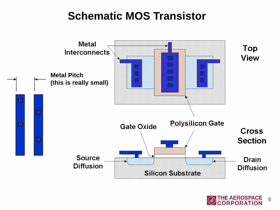
Schematic MOS Transistor
Metal Pitch(this is really small)

6
Micro/Nanoelectronics:The Evolution of a Revolution
Year: ½-Pitch(nm)
Die Size(mm2)
Billions of Bitsper Dice
Die Size(mm2)
Dynamic RAM: High Volume μPs:Billions of
Transistors
2007 65 93 2.15 280 0.7732008 57 74 2.15 222 0.7732010 45 93 4.29 280 1.5462012 36 59 4.29 353 3.0922015 25 59 8.59 353 6.184
2020 14 74 34.4 222 12.37
From the International Technology Roadmap for SemiconductorsExecutive Summary: http://www.itrs.net/Links/2007ITRS/ExecSum2007.pdf

7
Spacecraft Computing Requirements
• Traditional spacecraft requirements 1- Command and telemetry processing: 0.010 MIPS- Attitude sensor processing: 0.025 MIPS- Attitude determination and control: 0.105 MIPS- Power management: 0.005 MIPS- Thermal control: 0.003 MIPS- Kalman filter: 0.080 MIPS
• Image processing requirements 2- QCIF (174 x 144) encoding @ 10 frame/s: 0.03 - 0.1 GIPS- CIF (352 x 288) encoding @ 30 frame/s: 0.5 - 5 GIPS
• Power requirements- 1.6 mW for 1 MIPS (Atmel AT91R40807 processor)
1- L. Jane Hansen, chapter 16 “Spacecraft Computer Systems,” in Space Mission Analysis and Design by W.L. Larson and J.R. Wertz, Microcosm Inc, 1995
2- Hon-Sup Philip Wong et al, “Nanoscale CMOS,” Proceedings of the IEEE, 87 # 4, April 1999

8
A Really Small Command and Control System
The 80286 microprocessor: ~1 MIPS @ 6 MHz134,000 transistors1.5-micron technology~8-mm square
DRAM
Processor A small satellite command and control computer, with 1 MB DRAM, can now fit on a sub 1-mm2 die.
Projections based on ITRS scaling

9
Custom CMOS
• The Metal Oxide Semiconductor Implementation Service (MOSIS) - Combines chip designs from multiple users into a single mask set- Users split non-recurring costs (like the mask set)- CMOS processes: 1.5-μm through 65-nm- SiGe BiCMOS processes: 0.5-μm through 0.13-μm- ~$1100 for 5 copies of a 2-mm square, 1.5-μm rule design
• Advantages of Custom CMOS:- Variable size and shape photodetectors for 400 to 1100-nm light- Variable size and shape microbolometers using MEMS post-processing- Inertial and other sensors are possible using MEMS post-processing- Radiation tolerance can be designed into transistors, amplifiers, etc.
• Disadvantages of Custom CMOS:- Design mistakes can be costly- Some processes are available only every 3 months- You can’t use their packaging service for optical detectors
10
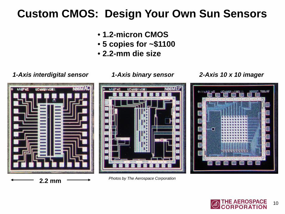
Custom CMOS: Design Your Own Sun Sensors
1-Axis binary sensor
2.2 mm
The
Aero
spac
e C
orpo
ratio
n
2-Axis 10 x 10 imager1-Axis interdigital sensor
• 1.2-micron CMOS• 5 copies for ~$1100• 2.2-mm die size
Photos by The Aerospace Corporation

11
Custom CMOS: Design Your Own Microbolometers
12 x 12 diode array6 x 6 thermocouple array
• 1.2-micron CMOS• 5 copies for ~$1100• 2.2-mm die size• Post-processing chemical etch required
6 x 6 thermocouple array
Photos by The Aerospace Corporation

12
Commercial Imagers for Picosatellites
Photo by The Aerospace Corporation
• Active pixel CMOS imagers are now cheap- Expensive CCD technology rarely needed
• Image compression chips are available• Megapixel imagers are common

13
Near Infrared Imaging with a CMOS Camera
Normal camera view Camera with RT-830 filter
• CMOS cameras respond to light between 300 and 1100-nm• Visible light ranges from ~400 to 700-nm• Remaining 700 to 1100-nm near-IR range can be useful
- Vegetation is very bright• Even color imagers can see 700 to 1100-nm range
Photos by The Aerospace Corporation

14
CMOS Imagers for Star Trackers
• Cannon EOS-20D• 18-mm f/3.5 lens
- 5.1-mm effective aperture• 2-second exposure• CMOS Star Camera:
- 1” diameter optic- 0.1-s exposure time- Stars to 4th magnitude
Photo by The Aerospace Corporation

15
Simple Sun Sensor for a CubeSat
• Apertured position sensitive detector (PSD)- Hamamatsu S7848 detector (4.8 x 4.1 x 1.8-mm)- PSD are is 2-mm square- 200-micron diameter aperture- 500-micron aperture-PSD seperation
• Simple, robust concept- Flown on AMSAT Phase 3D satellite- Will fly on AMSAT Eagle and KiwiSat
• BK-7 glass window in this design- Radiation shielding- UV light cutoff below 350-nm wavelength
(protects plastic from UV degradation)

16
Simple Sun Sensor for a CubeSat
PSD with Aperture Plate Sun and Earth Sensor PC Board
• Sun sensor and single infrared detector on same board • PC board size is 3.3 x 2.5-cm
Photo by The Aerospace Corporation
Photo by The Aerospace Corporation

17
Sun Sensor for a CubeSat: Ground Data
• Tested at AM0 conditions- SpectraLabs X-25 simulator
• Total range: +/- 50o
• Linear range: +/- 30o
- Plastic index of refractionimportant beyond 30o inc.
- Raw accuracy: +/- 2o

18
Micro/Nano/Picosatellite Attitude Sensors
• Sun sensors:- PSD-based sensors can be small and simple.- Custom CMOS sensors can have better performance, but will cost more.- CMOS imager-based sensors will have best performance when coupled
with algorithms that perform Earth light rejection and centroid analysis
• Earth and horizon sensors:- Single temperature sensors operating in the 5 to 12-micron range exist.- Microbolometer infrared detectors are available for a few thousand dollars.- Custom CMOS microbolometer arrays can be made for a few hundred dollars
(recurring costs assuming 5 copies at $1100 total)
• Magnetic field sensors:- Giant magnetoresistive sensors readily available, sensitive, and cheap.- Picosatellite magnetometers usually swamped by nearby currents and batteries.
• MEMS rate sensors:- Noise density of 0.05o/s/Hz1/2 available; e.g., from Analog Devices.- MEMS sensors are O.K. for several minutes, but not for navigation.

19
COTS MEMS Rate Gyro Performance levelsProvider Model Max. Rate
(deg/s)Noise
(deg/sec/Hz1/2)
AnalogDevices
ADXRS150 150 0.05
SiliconSensingSys.
CRS02 300 0.75
CRS03-02 100 0.05 (3-10 Hz)
CRS04 150 1.2
Kionix KGF01-075 75 0.14
AnalogDevices
ADIS16255 80 to 320 0.05

20
The Analog Devices ADXL202/210 Accelerometers
• Integrated 2-axis Accelerometers- ADXL202: +/- 2 g range- ADXL210: +/- 10g range
• Low Power- 3 to 5.25 V- Less than 0.6 mA
• Wide Frequency Response- DC to 5 kHz
• Low Noise- 500 μg/(Hz)1/2 noise floor
• Analog and Digital Outputs
• Good for monitoring thrusters
Pho
to b
y Th
e A
eros
pace
Cor
pora
tion
21
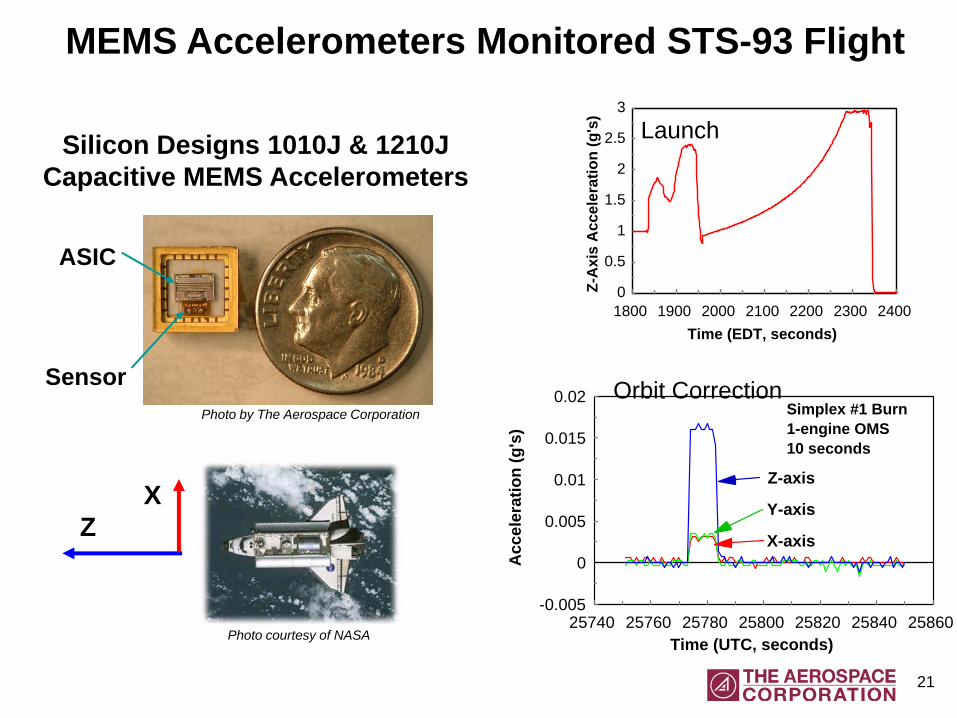
MEMS Accelerometers Monitored STS-93 Flight
Silicon Designs 1010J & 1210JCapacitive MEMS Accelerometers
0
0.5
1
1.5
2
2.5
3
Z-A
xis
Acc
eler
atio
n (g
's)
1800 1900 2000 2100 2200 2300 2400 Time (EDT, seconds)
Launch
Orbit Correction
-0.005
0
0.005
0.01
0.015
0.02
Acc
eler
atio
n (g
's)
25740 25760 25780 25800 25820 25840 25860 Time (UTC, seconds)
Z-axis
Y-axis
X-axis
Simplex #1 Burn1-engine OMS10 seconds
ZX
Sensor
ASIC
Photo by The Aerospace Corporation
Photo courtesy of NASA

22
Summary• Until the year 2000, only 2 active picosatellites were launched
- Most picosatellites were passive objects
• The picosatellite era started with Stanford’s OPAL satellite- Six picosatellites ejected in 2000- Two picosatellites ejected in 2001- CubeSats dominate starting in 2003
• Evolving micro/nanoelectronics and MEMS enabled intelligentpicosatellites
• Digital micro/nanoelectronics is not really a problem for picosatellites- Microprocessor performance of ~1000 MIPS/W is available- Gigabytes of data can be stored in a 1-cm2 memory card
• Miniaturized attitude sensors are needed for capable picosatellites- Pointing of sensors and optics- Pointing of medium to high gain antennas to increase downlink rates
• These sensors are either available or can be custom-fabricated usingCMOS prototyping services

23
I gratefully acknowledge The Aerospace Corporation’s Independent Research and Development program and its former Corporate Research Initiative in MEMS and Microtechnology for funding the development of CMOS-based sensors.
I also want to thank The Aerospace Institute for sponsoring my chapters “The History of Small Satellites” and “The Future of Small Satellites” in the upcoming AIAA/Aerospace Institute book Small Satellites: Past, Present and Future to be published in Nov/Dec 2008.
Acknowledgements