micromechanics of recycled composites for …. oral... · s. pimenta*, s.t. pinho, p. robinson...
TRANSCRIPT
18TH
INTERNATIONAL CONFERENCE ON COMPOSITE MATERIALS
1 Introduction
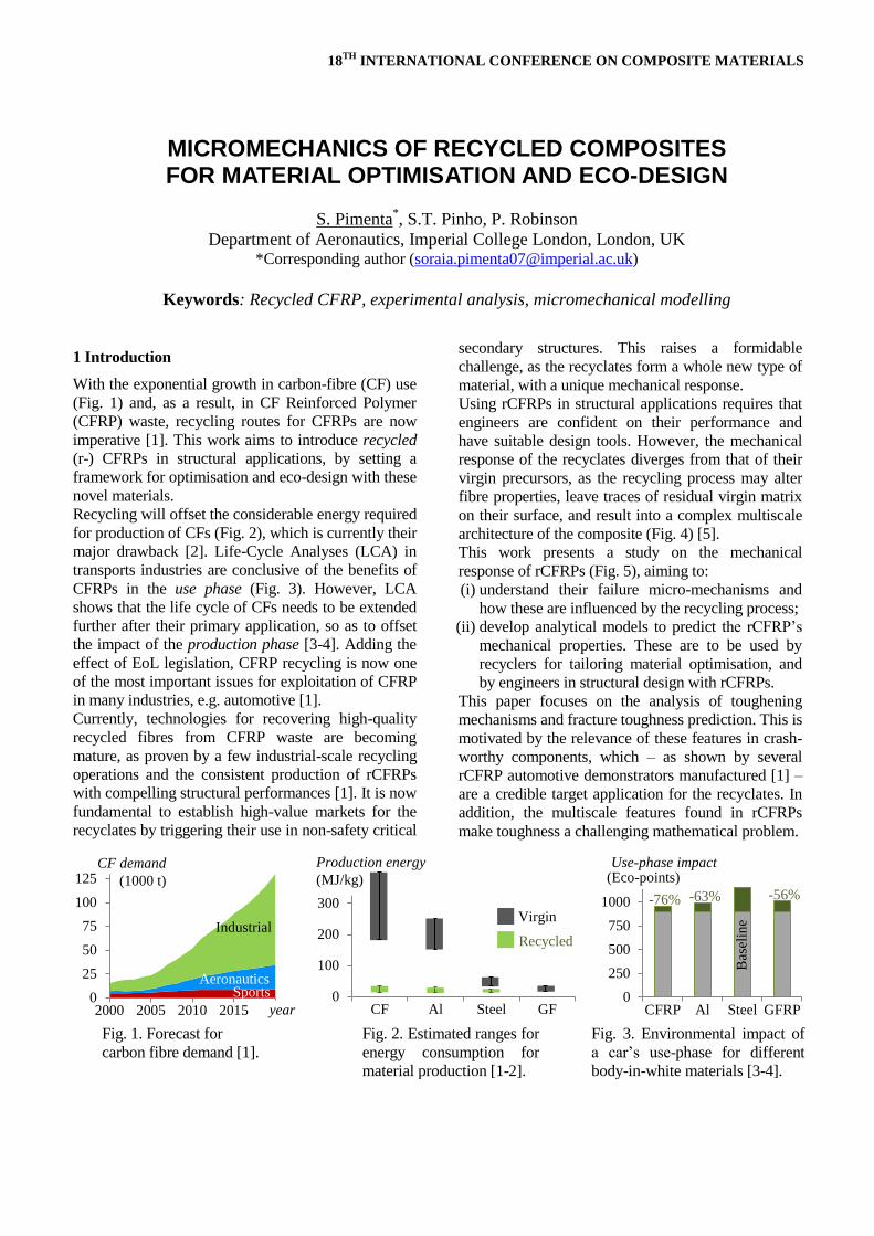
With the exponential growth in carbon-fibre (CF) use
(Fig. 1) and, as a result, in CF Reinforced Polymer
(CFRP) waste, recycling routes for CFRPs are now
imperative [1]. This work aims to introduce recycled
(r-) CFRPs in structural applications, by setting a
framework for optimisation and eco-design with these
novel materials.
Recycling will offset the considerable energy required
for production of CFs (Fig. 2), which is currently their
major drawback [2]. Life-Cycle Analyses (LCA) in
transports industries are conclusive of the benefits of
CFRPs in the use phase (Fig. 3). However, LCA
shows that the life cycle of CFs needs to be extended
further after their primary application, so as to offset
the impact of the production phase [3-4]. Adding the
effect of EoL legislation, CFRP recycling is now one
of the most important issues for exploitation of CFRP
in many industries, e.g. automotive [1].
Currently, technologies for recovering high-quality
recycled fibres from CFRP waste are becoming
mature, as proven by a few industrial-scale recycling
operations and the consistent production of rCFRPs
with compelling structural performances [1]. It is now
fundamental to establish high-value markets for the
recyclates by triggering their use in non-safety critical
secondary structures. This raises a formidable
challenge, as the recyclates form a whole new type of
material, with a unique mechanical response.
Using rCFRPs in structural applications requires that
engineers are confident on their performance and
have suitable design tools. However, the mechanical
response of the recyclates diverges from that of their
virgin precursors, as the recycling process may alter
fibre properties, leave traces of residual virgin matrix
on their surface, and result into a complex multiscale
architecture of the composite (Fig. 4) [5].
This work presents a study on the mechanical
response of rCFRPs (Fig. 5), aiming to:
(i) understand their failure micro-mechanisms and
how these are influenced by the recycling process;
(ii) develop analytical models to predict the rCFRP’s
mechanical properties. These are to be used by
recyclers for tailoring material optimisation, and
by engineers in structural design with rCFRPs.
This paper focuses on the analysis of toughening
mechanisms and fracture toughness prediction. This is
motivated by the relevance of these features in crash-
worthy components, which – as shown by several
rCFRP automotive demonstrators manufactured [1] –
are a credible target application for the recyclates. In
addition, the multiscale features found in rCFRPs
make toughness a challenging mathematical problem.
Fig. 1. Forecast for
carbon fibre demand [1].
Fig. 2. Estimated ranges for
energy consumption for
material production [1-2].
Fig. 3. Environmental impact of
a car’s use-phase for different
body-in-white materials [3-4].
0
25
50
75
100
125
2000 2005 2010 2015 2020
AeronauticsSports
Industrial
CF demand
(1000 t)
year0
100
200
300
CF Al Steel GF
Virgin
Recycled
Production energy
(MJ/kg)
0
250
500
750
1000
1250
CFRP Al Steel GFRP
Use-phase impact
-56%-63%-76%
Bas
elin
e
(Eco-points)
MICROMECHANICS OF RECYCLED COMPOSITES FOR MATERIAL OPTIMISATION AND ECO-DESIGN
S. Pimenta*, S.T. Pinho, P. Robinson
Department of Aeronautics, Imperial College London, London, UK *Corresponding author ([email protected])
Keywords: Recycled CFRP, experimental analysis, micromechanical modelling

In this paper, Section 2 summarises the experimental
analysis of rCFRPs, which forms the physical basis
for model development and validation in Section 3.
The outcomes of this work are discussed in Section 4,
and the main conclusions summarised in Section 5.
2 Experimental analysis of recycled CFRP
2.1 Materials and experimental procedures
Three different rCFRPs ( , and ) were thoroughly
analysed experimentally; all materials had an epoxy
resin reinforced by rCFs (reclaimed by pyrolysis) in a
discontinuous and multidirectional architecture. The
reinforcement scales (from single fibres to large
bundles) were very different in all materials, due to
the different recycling routes used (Table 1).
The experimental study [5] covers a comprehensive
set of procedures to fully characterise the recyclates at
the micro, meso and macro scales, so as to provide an
in-depth understanding for model development as
well as providing the required input properties:
Single Fibre Tensile Tests (SFTT) and Single Fibre
Pull-Out tests, for mechanical characterisation of
fibres and fibre-resin interfaces;
Scanning Electron Microscopy (SEM) of fibres, for
morphology and diameter characterisation;
Optical Microscopy (OM) of rCFRP samples for
studying the reinforcement architecture, including
the statistical characterisation of length, orientation
and width distributions of fibres and bundles;
Mechanical testing of rCFRP, for characterisation
of elastic properties and strength;
Compact Tension (CT) tests, for measurement of
fracture toughness and R-curves for the rCFRPs;
Analysis of failure and toughening mechanisms,
using in-situ OM and fracture surface SEM.
2.2 Experimental results
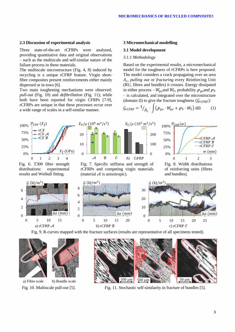
Single-fibre analyses showed very mild effects of the
pyrolysis process, as the rCF performance was close
to that of the virgin (v-) precursors (fibre morphology
in Fig. 4, fibre strength in Fig. 6). The rCFRPs also
compared well with Aluminium and phenolic Glass-
Fibre Reinforced Polymer (GFRP) (Fig. 7).
The rCFRPs featured multiscale reinforcements (Fig.
4) ranging from Ø5 μm rCFs to 7 mm wide bundles.
As shown by width Cumulative Density Functions
(CDFs, Fig. 8), material had most fibres dispersed,
while material featured the widest bundles.
The CT tests showed bundles arresting crack growth
and locally toughening the rCFRPs through pull-out
and defibrilation (Fig. 9). As architectures get coarser
( ), fracture surfaces become more
irregular, crack propagation stabilises, and the rCFRP
toughness increases considerably.
The analysis of failure and toughening mechanisms
showed self-similar features throughout the scales:
fibres and bundles are similarly pulled-out (Fig. 10),
and the defibrillation within fibre bundles presents
stochastic fractal patterns (Fig. 11).
Table 1: Description of the rCFRPs analysed
rCFRP Waste source Recycler Remanufacturer Fibre type Matrix type
Manuf. waste RCF Ltd U. Nottingham Toray T300 ACG MTM57
Manuf. waste MIT Boeing Toray T300 HexFlow RTM 6
EoL component MIT Boeing Toray T800 HexFlow RTM 6
Fig. 4. rCFRP multiscale reinforcement, featuring
dispersed fibres – originated from clean rCFs – and
large bundles – held together by residual matrix [5].
Fig. 5. Overall methodology for the analysis of
recycled composites for material optimisation and
eco-design.
500 μm
fibre bundle
dispersed phase
clean rCFs
residual matrixClosing the loop in the
CFRP life cycle
Guidelines for material optimisation
Design tools for structural applications
Predicting performance
Analytical modelling
Experimental study
Understanding response
FE analysis
3
MICROMECHANICS OF RECYCLED COMPOSITES
2.3 Discussion of experimental analysis
Three state-of-the-art rCFRPs were analysed,
providing quantitative data and original observations
– such as the multiscale and self-similar nature of the
failure process in these materials.
The multiscale microstructure (Fig. 4, 8) induced by
recycling is a unique rCFRP feature. Virgin short-
fibre composites present reinforcements either mainly
dispersed or in tows [6].
Two main toughening mechanisms were observed:
pull-out (Fig. 10) and defibrillation (Fig. 11); while
both have been reported for virgin CFRPs [7-9],
rCFRPs are unique in that these processes occur over
a wide range of scales in a self-similar manner.
3 Micromechanical modelling
3.1 Model development
3.1.1 Methodology
Based on the experimental results, a micromechanical
model for the toughness of rCFRPs is here proposed.
The model considers a crack propagating over an area
, pulling out or fracturing every Reinforcing Unit
(RU, fibres and bundles) it crosses. Energy dissipated
in either process – and , probability and
– is calculated, and integrated over the microstructure
(domain ) to give the fracture toughness :
⁄ ∫( ) (1)
Fig. 6. T300 fibre strength
distributions: experimental
results and Weibull fitting.
Fig. 7. Specific stiffness and strength of
rCFRPs and competing virgin materials
(material is anisotropic).
Fig. 8. Width distributions
of reinforcing units (fibres
and bundles).
a) rCFRP b) rCFRP c) rCFRP
Fig. 9. R-curves mapped with the fracture surfaces (results are representative of all specimens tested).
a) Fibre scale b) Bundle scale
Fig. 10. Multiscale pull-out [5]. Fig. 11. Stochastic self-similarity in fracture of bundles [5].
0%
25%
50%
75%
100%
0 1 2 3 4
v
RCF
MIT
f GPa
f
vCFrCF rCF
0
10
20
0
100
200
GFRPAl0%
25%
50%
75%
100%
0 1 2 3
rCFRP rCFRP rCFRP
mm
0
2
4
6
0 5 10 15 20 25 30 35
0
2
4
6
8
0 5 10 15 20 25 30 35
0
10
20
30
0 5 10 15 20 25 30 35
50 μm500 μm100 μm

3.1.2 Pull-out work of reinforcing units
The model for (Fig. 12) assumes a unilaterally
debonded RU (length ), being pulled-out at an
angle from an elastic foundation with stiffness .
The pulled-out length is progressively increased,
until either the RU is completely pulled ( ,
=0) or fails during the process (at , =1).
Four energy dissipation sources are considered:
Friction (coefficient ) due to residual interfacial
stresses at the fibre-matrix interface, . This
acts along the RU’s effective perimeter generating a pull-out force:
(2)
Friction due to the snubbing effect [8] from the
RU’s deflection on the foundation (Fig. 12b).
This creates a distributed force e
on the supported side, generating a pull-out force:
∫ | |
(3)
where results from the sinusoidal distribution of
contact stresses on the RU’s surface.
Sudden release of bending energy at the end of
pull-out. This is represented by:
∫ ⌋
(4)
where for complete pull-out (Fig. 12c) or
for RU failure during pull-out (Fig. 12b).
Fracture energy of the RU ( ), included if the
RU maximum stresses reach its strength ( =1).
Finally, the pull-out work of a RU is given by:
∫ (
)
(5)
3.1.3 Fracture of reinforcing units
The multiscale rCFRP architecture promotes a size
effect in the strength and toughness of RUs; these
may fail before debonding (with a probability
) or during the pull-out.
Weilbull’s theory – with associated fibre strength
distribution [10] – is here extended to the
analysis of embedded fibres. In a discontinuous CFRP
with a plastic interface (strength ), the stress field
in a fibre during debonding is linear, so the strength
distribution of the debonding fibre is:
a) Before pull-out b) During pull-out c) Complete pull-out
Fig. 12. Pull-out model for reinforcing units (fibres or bundles).
Fig. 13. Strength scaling model:
sequence of fibre failures leading
to level-1 bundle failure.
Fig. 14. Idealised stochastic fractal
fracture surface of bundles.
Fig. 15. Geometric model for
integration of energies over
the rCFRP’s architecture.
(∏[
(
)]
) (6)
bonded fibre-end
debonded fibre-end
macroscopic crack
elastic foundation
crack faces
=
anti-symmetry line
=
crack faces
1st fibre failure
2a
1
2b
IF 2nd fibre survives
2
1
macroscopic crack

5
MICROMECHANICS OF RECYCLED COMPOSITES
Expanding Eq. 6, the probability of fibre failure
before debonding ( in Eq. 1) becomes:
For scaling the strength of fibres to bundles, an
extension of a hierarchical model for dry bundles [11]
is proposed. The main original contribution is the
inclusion of a plastic matrix, which results into (i)
stress concentrations around a break being limited to
the recovery length (Fig. 13), and (ii) only fibre
breaks closer than result in final bundle failure.
The strength distribution of a level-1 bundle is
derived from the failure sequence of its 2 fibres (Fig.
13); a hierarchical failure process is then continued,
until the entire bundle section has failed (Fig. 14).
3.1.4 Integration over the reinforcement architecture
The probabilities for the variables in the integration
domain {( )} are related to the
experimentally measured Probability Density
Functions (PDFs) of length, orientation and width of
RUs – respectively , and (Fig. 15):
{ ( )
(8)
Assuming , and to be independent, then:
( ) (9)
The total number of RUs in the composite is
related to the reinforcement fraction by [6]:
( ̅ )̅ ⁄ (10)
Substituting Eq. 8-10 in Eq. 1 fully defines the
integration scheme for calculating .
3.2 Modelling results
The predictions for fibre pull-out work ( po 5 μm,
varying orientations ) are shown in Fig. 16, together
with literature [7] and FE (Fig. 17) results.
The results from the hierarchical fracture model for
the effect of filament count in bundle strength are
shown in Fig. 18. As the bundle size increases, both
the average strength and the variability are reduced.
Analytical and experimental fracture toughness
results are compared in Fig. 19. Parametric studies are
shown in Fig. 19b for the coefficient of friction , and
in Fig. 20 for micromechanical fibre properties.
( ) [
(
)
] (7)
Fig. 16. Predictions for fibre pull-
out work: analytical model vs. FE
and literature [6] results.
Fig. 17. Detail of the Finite Elements
(FE) analysis for validation of the
pull-out model.
Fig. 18. Strength distributions
for bundles with different
filament counts.
a) Experimental R-curves and predictions b) Anisotropy of experimental results
and modelling predictions for rCFRP Fig. 20. Sensitivity study on the
effect of fibre properties at the
toughness of rCFRP . Fig. 19. Model predictions vs. experimental results.
k = 20Gpak = 9.5 Gpak = 4 Gpa
0
1
2
0 20 40 60
Wf (FE)
Fu & Lauke
Current model:
FE results
Fu & Lauke [7]
e 20 GPa e 9.5 GPa e 4.0 GPa
crack faces
fibre
epoxy layer
rCFRP foundation
0%
25%
50%
75%
100%
0 5 10
18
1K
8K33K
GPa
0
10
20
30
0 10 20 30 40 50
experimentspredictions
0
1
2
3
4
0 30 60 90
Series1
experimentspredictions
1.00
0.50
0.75
0.25
-75%
-50%
-25%
0%
25%
50%
-50% -25% 0% 25%
E (Gpa)
X (Gpa)
4 Discussion
Following an extensive experimental investigation, an
analytical model to predict the fracture toughness of
multiscale rCFRPs was developed. This was based on
the pull-out and fracture of fibres and bundles, acting
over the entire range of reinforcement scales.
The new pull-out model was able to capture the
response predicted by very complex 3D FE models
(Fig. 16 and 17), showing an improvement over
literature models [7]. The hierarchical scaling laws
proposed for the strength of fibres and bundles (Fig.
18) also reproduce the response reported for virgin
composites [10], and extend the applicability of dry
fibre bundle models [11] to composites.
These new approaches – and their novel combination
in a multiscale model – were applied to the rCFRPs
studied. Comparing the predictions with experimental
results is extremely encouraging, as toughnesses one
order of magnitude apart are reproduced accurately by
the model (Fig. 19a). For the anisotropic material
(Fig. 19b), the model is able to capture the variation
of toughness with crack orientation .
Several sensitivity studies were performed. The fibre-
matrix friction coefficient is key for the toughness
of dispersed rCFRPs ( , Fig. 19b), while fibre
strength is critical for coarser materials ( , Fig. 20).
5 Conclusions
This paper presented in-depth analysis and modelling
of toughening mechanisms of rCFRPs.
The experimental programme revealed a unique and
complex multiscale architecture in the recyclates,
with a critical role on their mechanical response. This
study showed that residual matrix is not necessarily a
recycling defect, as it actually enhances the fracture
toughness of rCFRPs. A thorough characterisation,
showing properties consistently reaching those of
conventional materials and detailing load transfer and
failure mechanisms, is raising confidence on rCFRPs
within the industry, especially the automotive one.
A physically-based analytical model, which provides
a unique tool for the prediction of properties of the
recyclates, was developed. The focus on the fracture
toughness, while requiring many challenging features
– e.g. a frictional pull-out model, strength scaling
laws, integration over a multiscale architecture – can
support the optimisation of recycling processes
towards crash-worthy materials, and their application
for eco-design of non-safety-critical structures.
Further development of design methodologies,
together with quality control of recycling processes,
are now vital for the application of rCFRPs in
structural components. Overcoming these challenges
will firmly establish the recyclates as green and high-
performance materials, and finally close the loop in
the CFRP life-cycle.
Acknowledgments
The funding provided by FCT under the project
SFRH/BD/44051/2008 is gratefully acknowledged.
The authors are also thankful to K.H. Wong and
S.J. Pickering (U. Nottingham), S. Line and S. Alsop
(RCF Ltd.), and P. George and W. Carberry (Boeing),
for providing recycled materials and relevant data.
References
[1] Pimenta S. and Pinho S.T., “Recycling carbon fibre reinforced polymers for structural applications”. Waste
Management, Vol. 31, pp. 378-392, 2011.
[2] Song Y.S. et al., “Life cycle energy analysis of fiber-
reinforced composites”. Composites Part-A, Vol. 40,
pp. 1257-1265, 2009.
[3] Duflou J.R. et al., “Environmental impact analysis of
composite use in car manufacturing”. CIRP Annals –
Manufact. Technol., Vol. 58, pp 9-12, 2009.
[4] Das S., “Life cycle assessment of carbon fiber-
reinforced polymer composites”. Int. J. Life Cycle
Assess., Vol. 16, pp 268-282, 2011.
[5] Pimenta S. et al., “Mechanical analysis and toughening
mechanisms of a multiphase recycled CFRP”,
Compos. Sci. Technol., Vol. 70, pp. 1713-1725, 2010.
[6] Harper L.T., “Discontinuous carbon fibre composites for automotive applications”. U. Nottingham, 2006.
[7] Fu S.Y. and Lauke B., “The fibre pull-out energy of
misaligned short fibre composites”. J. Materials
Science, Vol. 32, pp. 1985-1993, 1997.
[8] Leung C.K.Y. and Li V.C., “Effect of fiber inclination on crack bridging stress in brittle fiber reinforced
brittle matrix composites”. J. Mech. Phys. Solids, Vol.
40, pp. 1333-1362, 1992.
[9] Laffan M.J. et al., “Measurement of the in situ ply
fracture toughness associated with mode I fibre tensile
failure in FRP. Part II”. Compos. Sci. Technol., Vol.
70, pp. 614-621, 2010.
[10] Wisnom M.R., “Size effects in the testing of fibre-
composite materials”. Compos. Sci. Technol., Vol. 59,
pp. 1937-1957, 1999.
[11] Newman W.I. and Gabrielov A.M., “Failure of
hierarchical distributions of fibre bundles”. Int. J.
Fracture, Vol. 50, pp. 1-14, 1991.