microfuge 20 series centrifuges instructions for use · the centrifuge weighs 13 kg/28.6 lb...
TRANSCRIPT
Instructions For Use
Microfuge 20 Series
Centrifuges
May 2013
Beckman Coulter, Inc.
250 S. Kraemer Blvd.
Brea, CA 92821 U.S.A.
B30162AA

Microfuge 20/20R
Centrifuges
PN B30162AA (May 2013)
Copyright ©2013 Beckman Coulter, Inc.
All rights reserved
No part of this document may be reproduced
or transmitted in any form or by any means,
electronic, mechanical, photocopying, recording, or
otherwise, without prior written permission from
Beckman Coulter, Inc.
Beckman Coulter and the stylized logo are trademarks of
Beckman Coulter, Inc. and are registered in the USPTO.
All other trademarks, service marks, products, or services
are trademarks or registered trademarks of their
respective holders.
Find us on the World Wide Web at:
www.beckmancoulter.com
Beckman Coulter Ireland, Inc.Mervue Business Park, Mervue Galway, Ireland 353 91 774068
Made in Germany
Printed in the U.S.A.

Revision Status
Initial Issue, 05/2013
Microfuge 20 Series Centrifuges Instructions for Use, version B30162AA
B30162AA iii

Revision Status
B30162AAiv

Safety Notice
Read all product manuals and consult with Beckman Coulter-trained personnel before attempting to operate the instrument. Do not attempt to perform any procedure before carefully reading all instructions. Always follow product labeling and manufacturer’s recommendations. If in doubt as to how to proceed in any situation, contact your Beckman Coulter Representative.
Alerts for Danger, Warning, Caution, Important, and Note
DANGER
DANGER indicates an imminently hazardous situation which, if not avoided,
will result in death or serious injury.
WARNING
WARNING indicates a potentially hazardous situation which, if not avoided,
could result in death or serious injury.
CAUTION
CAUTION indicates a potentially hazardous situation, which, if not avoided,
may result in minor or moderate injury. It may also be used to alert against unsafe
practices.
IMPORTANT IMPORTANT is used for comments that add value to the step or procedure being performed.
Following the advice in the Important adds benefit to the performance of a piece of equipment or to a
process.
NOTE NOTE is used to call attention to notable information that should be followed during installation, use,
or servicing of this equipment.
Safety During Installation and/or Maintenance
The centrifuge weighs 13 kg/28.6 lb (nonrefrigerated model) without rotor, or 32 kg/70.5 lb (refrigerated model) without rotor. DO NOT attempt to lift or move one of them without assistance from another person.
Any servicing of this equipment that requires removal of any covers can expose parts which involve the risk of electric shock or personal injury. Make sure that the power switch is turned off and the instrument is disconnected from the main power source by removing the Mains (power) plug from the outlet receptacle, and refer such servicing to qualified personnel.
Do not replace any centrifuge components with parts not specified for use on this instrument.
B30162AA v

Safety Notice
Electrical Safety
Electrical Safety
To reduce the risk of electrical shock, this equipment uses a three-wire electrical cord and plug to connect this equipment to earth-ground. To preserve this safety feature:
• Make sure that the matching wall outlet receptacle is properly wired and earth-grounded. Check that the line voltage agrees with the voltage listed on the name-rating plate affixed to the instrument.
• Never use a three-to-two wire plug adapter.
• Never use a two-wire extension cord or a two-wire non-grounding type of multiple-outlet receptacle strip.
• Do not place containers holding liquid on or near the chamber door. If they spill, liquid may get into the instrument and damage electrical or mechanical components.
• Work on the power supply system must be performed by certified electricians.
• Inspect the electrical equipment of the unit regularly. Defects such as loose or burnt cables must be eliminated immediately.
Safety Against Risk of Fire
This centrifuge is not designed for use with materials capable of developing flammable or explosive vapors. Do not centrifuge such materials (such as chloroform or ethyl alcohol) in this centrifuge nor handle or store them within the 30 cm (12 inches) clearance envelope surrounding the centrifuge. Do not use the centrifuge within hazardous locations.
Mechanical Safety
For safe operation of the equipment, observe the following:
• Use only the rotors and accessories designed for use in this centrifuge.
• Before starting the centrifuge, make sure that the rotor tie-down screw is securely fastened.
• Do not exceed the maximum rated speed of the rotor in use.
• NEVER attempt to slow or stop the rotor by hand.
• NEVER attempt to override the door interlock system while the rotor is spinning.
• Maintain a 30 cm (12 inches) clearance envelope around the centrifuge while it is running. During operation you should come within the envelope only to adjust instrument controls, if necessary.
• Never bring any flammable substances within the 30 cm (12 inches) area surrounding the centrifuge.
• Never operate the instrument without a rotor installed.
B30162AAvi

Safety Notice
Chemical and Biological Safety
• If the instrument housing becomes damaged do not use the instrument. Contact Beckman Coulter Field Service (1-800-742-2345 in the United States; outside the U.S. contact your local Beckman Coulter office or visit us at http://www.beckmancoulter.com).
Chemical and Biological Safety
Normal operation may involve the use of solutions and test samples that are pathogenic, toxic, or radioactive. Such materials should not be used in this instrument unless all necessary safety precautions are taken.
• Observe all cautionary information printed on the original solution containers prior to their use.
• Handle body fluids with care because they can transmit disease. No known test offers complete assurance that they are free of micro-organisms. Some of the most virulent—Hepatitis (B and C) and HIV (I–V) viruses, atypical mycobacteria, and certain systemic fungi—further emphasize the need for aerosol protection. Handle other infectious samples according to good laboratory procedures and methods to prevent spread of disease. Because spills may generate aerosols, observe proper safety precautions for aerosol containment. Do not run toxic, pathogenic, or radioactive materials in this centrifuge without taking appropriate safety precautions. Biosafe containment should be used when Risk Group II materials (as identified in the World Health Organization Laboratory Biosafety Manual) are handled; materials of a higher group require more than one level of protection.
• Dispose of all waste solutions according to appropriate environmental health and safety guidelines.
• Do not centrifuge materials that could result in a hazardous chemical reaction.
It is your responsibility to decontaminate the centrifuge and accessories before requesting service by Beckman Coulter.
B30162AA vii

Safety Notice
Chemical and Biological Safety
B30162AAviii

Contents
Revision Status, iii
Safety Notice, v
Introduction, xv
CHAPTER 1: Description, 1-1
Introduction, 1-1
Centrifuge Function and Safety Features, 1-1Centrifuge Function, 1-1Models, 1-2Safety Features, 1-3
Chassis, 1-3Housing, 1-3Door, 1-3Rotor Chamber, 1-4Drive, 1-4
Temperature Sensing and Control (refrigerated models only), 1-4
Controls and Indicators, 1-5Power Switch, 1-5Control Panel, 1-5
System Keys, 1-5Program Keys, 1-6Digital Displays, 1-6
Name Rating Plate, 1-7
Microfuge 20 Nonrefrigerated Model Specifications, 1-8
Microfuge 20R Refrigerated Model Specifications, 1-9
Available Rotors, 1-10
CHAPTER 2: Operation, 2-1
Introduction, 2-1
Run Procedure, 2-2Preparation and Loading, 2-2
ix
Contents
Entering Run Parameters, 2-4Menu Key Sequence, 2-4Setting Run Speed, 2-5To set the speed, 2-5Setting Run Time, 2-5To set a timed run, 2-6To start a continuous run, 2-6To stop a continuous run, 2-7Setting Run Temperature (Microfuge 20R refrigerated models
only), 2-7To set the run temperature, 2-7Rotor Code Selection, 2-8To select the correct rotor, 2-8Precooling the centrifuge (20R refrigerated models only), 2-8To precool the centrifuge, 2-8Setting Acceleration and Deceleration Rates, 2-9To activate both Soft-start and Soft-stop functions , 2-9To activate only the Soft-stop function , 2-10To deactivate both Soft-start and Soft-stop functions , 2-10
Starting a Run, 2-10To start a run, 2-10
Short Run (Quick Run) Function, 2-11To perform a quick run on the non-refrigerated Microfuge
20, 2-11To perform a quick run on the refrigerated Microfuge 20R, 2-12
Changing Parameters During a Run, 2-12To change the speed during a run, 2-12To change the run time during a run, 2-13To change the temperature during a run (Microfuge 20R
only), 2-13Stopping a Run, 2-13
To stop a run in progress, 2-13
Unloading, 2-14
Summary of Run Procedures, 2-14
Saving and Using Programs, 2-16Saving Settings, 2-16
To save settings into a program, 2-16To run a saved program, 2-17To change a saved program, 2-17
CHAPTER 3: Troubleshooting, 3-1
Introduction, 3-1
User Messages, 3-1To clear the problem or error, 3-2
Other Possible Problems, 3-5
Accessing the Centrifuge in Case of Power Failure, 3-6
x

Contents
To gain emergency access the centrifuge, 3-6
CHAPTER 4: Care and Maintenance, 4-1
Introduction, 4-1
Maintenance, 4-2Preventive Maintenance, 4-2
Cleaning, 4-2
Decontamination, 4-4
Sterilization and Disinfection, 4-4
Storage and Transport, 4-4Storage, 4-4
Notes on Transport, 4-4Returning a Centrifuge, 4-5
Supply List, 4-5Replacement Parts, 4-5Other, 4-5
APPENDIX A: Installation, A-1
Introduction, A-1
Installing the Instrument, A-1To install the centrifuge, A-2
Electrical Requirements, A-3
Test Run, A-5
APPENDIX B: Table of Hazardous Substance’sName and Concentration, B-1
Beckman Coulter, Inc.Microfuge 20 Series Centrifuge Warranty
Related Documents
xi

xii
Illustrations
Illustrations
1.1 Microfuge 20 (A) and Microfuge 20R (B) Front View, 1-1
1.2 Microfuge 20R (A) and Microfuge 20 (B) Rear view, 1-2
1.3 Interior View of the Rotor Chamber, 1-4
1.4 Microfuge 20 and Microfuge 20R Control Panels, 1-5
1.5 Digital Display showing all possible displays, Microfuge 20R shown, 1-7
2.1 Tapered Sleeve Side View, 2-3
2.2 Default Parameters on First-Time Use, Microfuge 20R shown, 2-4
3.1 Error message example, 3-2
3.2 Removing the Emergency Access Plug, 3-7
3.3 Manually releasing the door lock with the Allen wrench, 3-7
A.1 Dimensions of the Non-Refrigerated Centrifuge, A-3
A.2 Dimensions of the Refrigerated Centrifuge, A-4

Tables
Tables
1.1 Display Definitions, 1-7
2.1 Acceleration and Deceleration Rates by Rotor (in minutes:seconds), 2-9
3.1 Error Message Chart, 3-3
3.2 Troubleshooting Chart, 3-5
xiii

Tables
xiv

Introduction
Certification
Beckman Coulter Microfuge 20 series centrifuges are manufactured in a facility that maintains certifications to ISO 9001:2008 or ISO 13485:2003. They have been designed and tested to be compliant (when used with Beckman Coulter rotors) with the the safety requirements for electrical equipment for laboratory use of applicable regulatory agencies. Declarations of conformity and certificates of compliance are available at www.beckmancoulter.com.
Scope of Manual
This manual is designed to familiarize you with the Beckman Coulter Microfuge 20 series centrifuges, their functions, specifications, operation, and routine operator care and maintenance. Beckman Coulter recommends that you read this entire manual, especially the Safety Notice section and all safety-related information, before operating the centrifuge or performing instrument maintenance.
The following introductory pages contain the instrument specifications, as well as space, electrical, and temperature conditions required for optimal centrifuge performance. A list of available rotors is also included.
• CHAPTER 1, Description provides a brief physical and functional description of the centrifuge, the operating controls and indicators, and system specifications.
• CHAPTER 2, Operation contains centrifuge operating procedures.
• CHAPTER 3, Troubleshooting lists diagnostic messages and other possible malfunctions, together with probable causes and suggested corrective actions.
• CHAPTER 4, Care and Maintenance contains procedures for routine operator care and maintenance, as well as a brief list of supplies and replacement parts.
• APPENDIX A, Installation contains instructions for installing and connecting the centrifuge.
• APPENDIX B, Table of Hazardous Substance’s Name and Concentration contains information required by Electronic Industry Standards of the People’s Republic of China.
NOTE If the centrifuge is used in a manner other than specified in this manual, the safety and performance of this equipment could be impaired. Further, the use of any equipment other than that recommended by Beckman Coulter has not been evaluated for safety. Use of any equipment not specifically recommended in this manual and/or the applicable rotor manual is the sole responsibility of the user.
B30162AA xv

Introduction
Conventions
Conventions
Certain symbols are used in the product labeling to call out safety-related and other important information. These international symbols may also be displayed on the centrifuge and are reproduced on the inside of the back cover of this manual.
Typographic Conventions
Certain typographic conventions are used throughout this manual to distinguish names of user interface components, such as keys and displays.
• Key names (for example, OPEN or START) and display names (for example, TEMP°C or SPEED) appear in bold type.
• Cursor keys, used to increment values up or down when setting parameters, are shown as up and
down arrows (� or �).
CFC-Free Centrifugation
To ensure minimal environmental impact, no CFCs are used in the manufacture or operation of Microfuge 20 series centrifuges.
Symbols and Labels
This section provides information for some labels and symbols appearing on the Microfuge 20 instrument housing. These labels and symbols may be associated with user-serviceable procedures. Individual hazards associated with a specific procedure in this manual may use these labels and symbols, and are included in Warnings or Cautions within the procedures for that task.
Biohazard
This caution symbol indicates biohazardous risk from possible patient specimen contamination.
B30162AAxvi

Introduction
Symbols and Labels
Caution Symbol
This symbol indicates a caution message and appears adjacent to an explanation or other symbols that define the caution.
High Voltage Danger
This symbol indicates high voltage is present or that there is a risk of electric shock when working in this area. Operation, replacement or servicing of any components where contact with bare, live hazardous parts could occur, possibly resulting in electric shock, should only be performed by your Beckman Coulter representative.
Protective Ground
This symbol is used to indicate a protective ground. This instrument must be properly grounded. Do not under any circumstances operate the instrument unless it is properly grounded.
Recycling Label
This symbol is required in accordance with the Waste Electrical and Electronic Equipment (WEEE) Directive of the European Union. The presence of this marking on the product indicates:
• the device was put on the European Market after August 13, 2005 and
A28219-AA
B30162AA xvii

Introduction
Symbols and Labels
• the device is not to be disposed of via the municipal waste collection system of any member state of the European Union.
It is very important that customers understand and follow all laws regarding the proper decontamination and safe disposal of electrical equipment. For Beckman Coulter products bearing this label, please contact your dealer or local Beckman Coulter office for details on the take-back program that will facilitate the proper collection, treatment, recovery, recycling and safe disposal of the device.
Risk of Fire Warning
Before replacing fuses, shut off power and disconnect the power cord. Failure to do so can cause electric shock and/or equipment damage. Replace fuses only with approved type and rating replacement fuse.
Electric Shock Warning
Operation, replacement or servicing of any components where contact with electronic components could occur can result in electric shock, and should only be performed by your Beckman Coulter representative.
Rotor Rotation
This label indicates the direction of the rotor rotation.
B30162AAxviii

Introduction
Symbols and Labels
China RoHS Caution Label
This label and materials declaration table (the Table of Hazardous Substance’s Name and Concentration) are to meet People’s Republic of China Electronic Industry Standard SJ/T11364-2006 “Marking for Control of Pollution Caused by Electronic Information Products” requirements.
This logo indicates that this electronic information product contains certain toxic or hazarous elements, and can be used safely during its environmental protection use period. The number in the middle of the logo indicates the environmental protection use period for the product. The outer circle indicates that the product can be recycled. The logo also signifies that the product should be recycled immediately after its environmental protection use period has expired. The date on the label indicates the date of manufacture.
Australian EMC Compliance Label
The C-Tick mark is intended for use on products that comply with Australian Communication Authority (ACA) EMC Requirements.
TUV-GS Label
The GS seal indicates that a product has been inspected in a national testing center and that production facilities have undergone an initial, as well as on ongoing, inspection. Only companies that meet these high standards may attach the GS seal next to the CE seal or CE label.
B30162AA xix

Introduction
Symbols and Labels
CE Label
This label indicates conformance to various directives set forth under European Union law.
Consult IFU Label
This label indicates that the Instructions for Use should be referred to for more information.
RoHS Conform Label
This label indicates that the product is compliant with the EU RoHS directive (2002/95/EC) pertaining to the Restriction of Hazardous Substances in Electrical and Electronic Equipment (EEE).
TUV-NRTL Label
This label indicates recognition by a Nationally Recognized Test Laboratory (NRTL) that the instrument has met the relevant product safety standards.
B30162AAxx

CHAPTER 1
Description
Introduction
This chapter provides a brief physical and functional description of Beckman Coulter Microfuge 20 series centrifuges. The operating controls and indicators are also described; instructions for their use are in CHAPTER 2, Operation. Chemical compatibilities of materials listed in this manual can be found in Chemical Resistances (publication IN-175). Refer to the applicable rotor manuals for rotor descriptions.
Centrifuge Function and Safety Features
Centrifuge Function
Figure 1.1 Microfuge 20 (A) and Microfuge 20R (B) Front View
1. Door
2. Display
3. Emergency Door Release
B30162AA 1-1
Description
Centrifuge Function and Safety Features
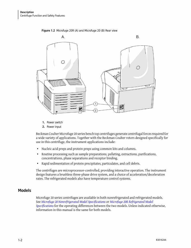
Figure 1.2 Microfuge 20R (A) and Microfuge 20 (B) Rear view
Beckman Coulter Microfuge 20 series bench top centrifuges generate centrifugal forces required for a wide variety of applications. Together with the Beckman Coulter rotors designed specifically for use in this centrifuge, the instrument applications include:
• Nucleic acid preps and protein preps using common kits and columns.
• Routine processing such as sample preparations, pelleting, extractions, purifications, concentrations, phase separations and receptor binding.
• Rapid sedimentation of protein precipitates, particulates, and cell debris.
The centrifuges are microprocessor-controlled, providing interactive operation. The instrument design features a brushless three-phase drive system, and a choice of acceleration/deceleration rates. The refrigerated models also have temperature control systems.
Models
Microfuge 20 series centrifuges are available in both nonrefrigerated and refrigerated models. See Microfuge 20 Nonrefrigerated Model Specifications or Microfuge 20R Refrigerated Model Specifications for the operating differences between the two models. Unless indicated otherwise, information in this manual is the same for both models.
1. Power switch
2. Power input
B30162AA1-2

Description
Chassis 1
Safety Features
Microfuge 20 series centrifuges have been designed and tested to operate safely indoors at altitudes up to 2000 m (6562 ft).
Instrument safety features include:
• An electromechanical door-locking mechanism to prevent operator contact with spinning rotors. When the door is closed it locks automatically. It can be unlocked only by pressing the OPEN key, and opened only when the power is on and the rotor is at rest.
• The centrifuge can only be started when the door is properly closed. The electrical lock must be locked. The door can only be opened when the rotor has stopped. If the door is opened by way of the emergency release system during operation, the centrifuge will immediately switch off and decelerate brakeless. If the door is open, the drive is completely separated from the mains power supply, that is, the centrifuge cannot be started.
• A steel barrier surrounds the rotor chamber to provide full operator protection.
• An overspeed system continuously monitors the rotor during centrifugation. The system includes a magnetic sensor on the drive motor. Throughout the run, checks are made to ensure that the rotor does not exceed set speed.
• The centrifuge feet, made of rubber, have been designed to minimize possible rotation in the event of a rotor mishap.
• An internal system continually monitors the sensor signals to confirm that they are within the expected values. Malfunctions are indicated by error messages with a number in the speed/RCF display. See Troubleshooting.
• For the Microfuge 20R, if the temperature inside the rotor chamber rises above 50 °C, the drive system will be switched off automatically. The centrifuge cannot be restarted until it has cooled.
Chassis
Housing
The centrifuge housing is made of high-performance engineered plastic, finished with urethane paint. The control panel is covered by a protective overlay made of coated polycarbonate.
Door
The door is made of a solid sheet of steel, encased in foam molding. In the center of the door is a window for strobe viewing. An electromechanical door lock system prevents a run initiation unless the door is shut and latched. The door is locked when a run is in progress and can be opened only when the rotor is stopped. In the event of a power failure, the door lock can be manually released for sample recovery (see CHAPTER 3, Troubleshooting).
B30162AA 1-3

Description
Temperature Sensing and Control (refrigerated models only)
Rotor Chamber
The rotor chamber is shown in Figure 1.3. The drive shaft and rubber boot surrounding the drive shaft are visible in the chamber bottom. A gasket system around the chamber opening ensures sealing. (Instrument gaskets have not been designed as bioseals for aerosol containment.)
Figure 1.3 Interior View of the Rotor Chamber
Drive
The asynchronous three-phase direct-drive motor is brushless for clean, quiet operation. A tie-down screw is used to attach the rotor to the drive shaft. The resilient suspension ensures that loads are not disturbed by vibration, and prevents damage to the drive shaft if an imbalance occurs during centrifugation. Maximum braking may be selected to reduce deceleration time, allowing fast processing of samples; alternately, delicate gradients may be preserved using slower deceleration.
Temperature Sensing and Control (refrigerated models only)
With the power on, the temperature control system is activated when the door is closed. The run temperature can be set between –10 and +40°C in refrigerated models. If no set temperature is entered, the centrifuge automatically selects the last entered temperature. (For the first run of a new centrifuge, the instrument selects 20°C as its operating temperature.) A thermistor in the rotor chamber continuously monitors chamber temperature. The micro-processor calculates the required chamber temperature to maintain the selected rotor temperature.
NOTE In the unlikely event of a complete cooling system failure, the drive switches off if the chamber
temperature goes above 50°C. Restarting the centrifuge is not possible until the chamber is cooled.
1. Drive Shaft
2. Boot
3. Gasket
B30162AA1-4

Description
Controls and Indicators 1
Controls and Indicators
Power Switch
The power switch is located on the centrifuge back panel (see Figure 1.2). This two-position rocker switch (I, on; O, off) controls electrical power to the centrifuge.
NOTE The power must be turned on before the chamber door can be opened.
Control Panel
The control panel is mounted at an angle on the front of the centrifuge and includes system keys, programming keys, and digital displays (see Figure 1.4).
Figure 1.4 Microfuge 20 and Microfuge 20R Control Panels
System Keys
The centrifuge operation is controlled through the system keys.
B30162AA 1-5

Description
Controls and Indicators
Program Keys
The program keys are used to set run parameters (a program consists of all of the parameters for a run). Except for the cursor keys, program keys show the parameters as they are input.
Digital Displays
Digital displays indicate rotor speed, run time, rotor chamber temperature, and the selected acceleration and deceleration profiles (see Figure 1.5). When the power is turned on, they show the operating parameters of the most recent run performed before the power was turned off. The displays serve a dual purpose.
• When the run parameters are being set (the input mode), the displays show the set values (those selected by the operator). When a run- parameter key (for example, MENU) is pressed, the appropriate display flashes to indicate that data can be entered.
START/STOP Pressing the START/STOP key causes a centrifuge run to begin. This key can also be
used to abort a deceleration process and restart the centrifuge.
The START/STOP key can be pressed to end a run. The centrifuge decelerates to a
complete stop according to the preselected deceleration curve. Deceleration can be
terminated and the centrifuge restarted by pressing START again.
OPEN Pressing the OPEN key unlatches the centrifuge door lock and allows the door to be
opened. The centrifuge accepts this command only when the rotor is completely
stopped.
QUICK RUN Manually pressing this key initiates a short run for as long as the key is pressed (applies
only to Microfuge 20).
� �
(cursor keys)
The cursor keys are up and down arrow keys, which can be pressed to increment
values up or down when setting parameters.
PROG Use this key to recall a previously saved program or to enter program mode to save
run parameters as a program.
PRECOOL
(refrigerated
model only)
Use this key to cool the rotor at a slow speed before a run starts. See Precooling the
centrifuge (20R refrigerated models only)for instructions on using this function.
MENU Use this key to scroll through and highlight the different run parameters. The
MENU key is pressed until the appropriate time, speed, or temperature display
function flashes. The parameter is set with the cursor keys.
B30162AA1-6

Description
Name Rating Plate 1
• The actual (real-time) operating conditions of the centrifuge are displayed during the run, after START is pressed.
NOTE The Error Message Chart also appear on the displays, when applicable. The centrifuge emits a series
of audible tones to alert the user to an error condition.
Figure 1.5 Digital Display showing all possible displays, Microfuge 20R shown
Name Rating Plate
The name rating plate is affixed to the rear of the centrifuge. Check that the line voltage agrees with the voltage listed on this name rating plate before connecting the centrifuge. Always mention the serial number and the model number shown when corresponding with Beckman Coulter regarding your centrifuge.
Table 1.1 Display Definitions
Display Description
Soft-Stop/Start Off Acceleration and Deceleration settings.
Short Run Displays while the Quick Run button (Microfuge 20 only) is pressed or when the
Start button is pressed and held (Microfuge 20R only).
Prog Displays to show the saved program number.
Set Displayed when the speed, run time or temperature is being set.
Actual Displayed to show the actual speed, run time and temperature.
Speed/RCF Displays the speed in either RPMs or RCF (� g)
Time Displays the time to be set for the run or the actual time while running.
Temperature Displays the temperature to be set for the run or the actual temperature while
running (Microfuge 20R only)
Rotor code Code 1: Not used
Code 2: FA241.5
Code 3: FA241.5P
Code 4: FA4x8.2P
Code 5: FA361.5
Code 6: Not used
B30162AA 1-7
Description
Microfuge 20 Nonrefrigerated Model Specifications
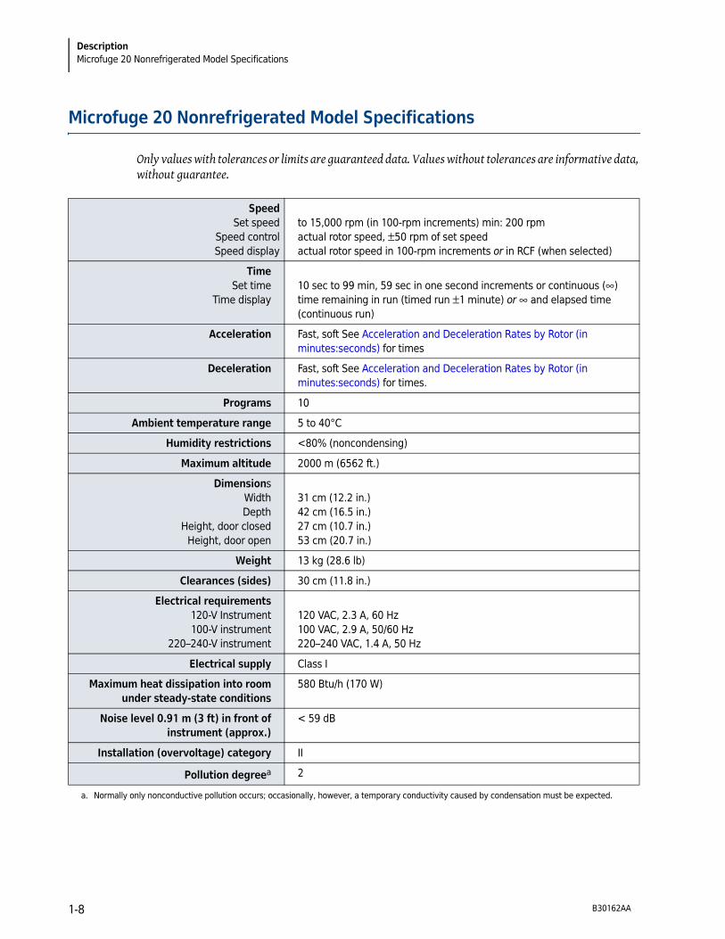
Microfuge 20 Nonrefrigerated Model Specifications
Only values with tolerances or limits are guaranteed data. Values without tolerances are informative data, without guarantee.
Speed
Set speed
Speed control
Speed display
to 15,000 rpm (in 100-rpm increments) min: 200 rpm
actual rotor speed, �50 rpm of set speed
actual rotor speed in 100-rpm increments or in RCF (when selected)
Time
Set time
Time display
10 sec to 99 min, 59 sec in one second increments or continuous (�)
time remaining in run (timed run �1 minute) or � and elapsed time
(continuous run)
Acceleration Fast, soft See Acceleration and Deceleration Rates by Rotor (in
minutes:seconds) for times
Deceleration Fast, soft See Acceleration and Deceleration Rates by Rotor (in
minutes:seconds) for times.
Programs 10
Ambient temperature range 5 to 40°C
Humidity restrictions <80% (noncondensing)
Maximum altitude 2000 m (6562 ft.)
Dimensions
Width
Depth
Height, door closed
Height, door open
31 cm (12.2 in.)
42 cm (16.5 in.)
27 cm (10.7 in.)
53 cm (20.7 in.)
Weight 13 kg (28.6 lb)
Clearances (sides) 30 cm (11.8 in.)
Electrical requirements
120-V Instrument
100-V instrument
220–240-V instrument
120 VAC, 2.3 A, 60 Hz
100 VAC, 2.9 A, 50/60 Hz
220–240 VAC, 1.4 A, 50 Hz
Electrical supply Class I
Maximum heat dissipation into room
under steady-state conditions
580 Btu/h (170 W)
Noise level 0.91 m (3 ft) in front of
instrument (approx.)
< 59 dB
Installation (overvoltage) category II
Pollution degreea 2
a. Normally only nonconductive pollution occurs; occasionally, however, a temporary conductivity caused by condensation must be expected.
B30162AA1-8
Description
Microfuge 20R Refrigerated Model Specifications 1
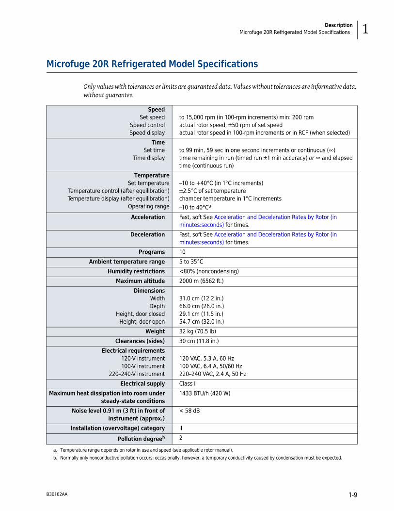
Microfuge 20R Refrigerated Model Specifications
Only values with tolerances or limits are guaranteed data. Values without tolerances are informative data, without guarantee.
Speed
Set speed
Speed control
Speed display
to 15,000 rpm (in 100-rpm increments) min: 200 rpm
actual rotor speed, �50 rpm of set speed
actual rotor speed in 100-rpm increments or in RCF (when selected)
Time
Set time
Time display
to 99 min, 59 sec in one second increments or continuous (�)
time remaining in run (timed run �1 min accuracy) or � and elapsed
time (continuous run)
Temperature
Set temperature
Temperature control (after equilibration)
Temperature display (after equilibration)
Operating range
–10 to +40°C (in 1°C increments)
�2.5°C of set temperature
chamber temperature in 1°C increments
–10 to 40°Ca
Acceleration Fast, soft See Acceleration and Deceleration Rates by Rotor (in
minutes:seconds) for times.
Deceleration Fast, soft See Acceleration and Deceleration Rates by Rotor (in
minutes:seconds) for times.
Programs 10
Ambient temperature range 5 to 35°C
Humidity restrictions <80% (noncondensing)
Maximum altitude 2000 m (6562 ft.)
Dimensions
Width
Depth
Height, door closed
Height, door open
31.0 cm (12.2 in.)
66.0 cm (26.0 in.)
29.1 cm (11.5 in.)
54.7 cm (32.0 in.)
Weight 32 kg (70.5 lb)
Clearances (sides) 30 cm (11.8 in.)
Electrical requirements
120-V instrument
100-V instrument
220–240-V instrument
120 VAC, 5.3 A, 60 Hz
100 VAC, 6.4 A, 50/60 Hz
220–240 VAC, 2.4 A, 50 Hz
Electrical supply Class I
Maximum heat dissipation into room under
steady-state conditions
1433 BTU/h (420 W)
Noise level 0.91 m (3 ft) in front of
instrument (approx.)
< 58 dB
Installation (overvoltage) category II
Pollution degreeb 2
a. Temperature range depends on rotor in use and speed (see applicable rotor manual).
b. Normally only nonconductive pollution occurs; occasionally, however, a temporary conductivity caused by condensation must be expected.
B30162AA 1-9
Description
Available Rotors
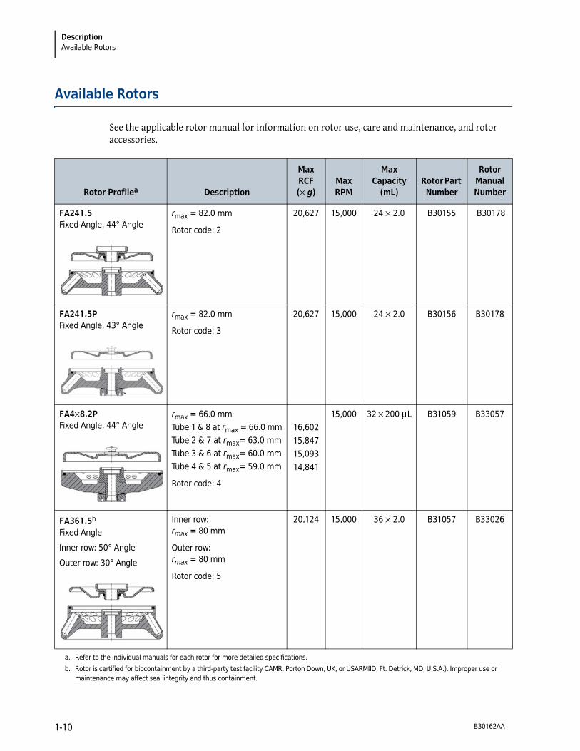
Available Rotors
See the applicable rotor manual for information on rotor use, care and maintenance, and rotor accessories.
Rotor Profilea Description
Max
RCF
(� g)
Max
RPM
Max
Capacity
(mL)
Rotor Part
Number
Rotor
Manual
Number
FA241.5
Fixed Angle, 44° Angle
rmax = 82.0 mm
Rotor code: 2
20,627 15,000 24 � 2.0 B30155 B30178
FA241.5P
Fixed Angle, 43° Angle
rmax = 82.0 mm
Rotor code: 3
20,627 15,000 24 � 2.0 B30156 B30178
FA4�8.2P
Fixed Angle, 44° Angle
rmax = 66.0 mm
Tube 1 & 8 at rmax = 66.0 mm
Tube 2 & 7 at rmax= 63.0 mm
Tube 3 & 6 at rmax= 60.0 mm
Tube 4 & 5 at rmax= 59.0 mm
Rotor code: 4
16,602
15,847
15,093
14,841
15,000 32 � 200 �L B31059 B33057
FA361.5b
Fixed Angle
Inner row: 50° Angle
Outer row: 30° Angle
Inner row:
rmax
= 80 mm
Outer row:
rmax
= 80 mm
Rotor code: 5
20,124 15,000 36 � 2.0 B31057 B33026
a. Refer to the individual manuals for each rotor for more detailed specifications.
b. Rotor is certified for biocontainment by a third-party test facility CAMR, Porton Down, UK, or USARMIID, Ft. Detrick, MD, U.S.A.). Improper use or
maintenance may affect seal integrity and thus containment.
B30162AA1-10
CHAPTER 2
Operation
Introduction
This section contains operating procedures for the centrifuge, using the rotor designed for use in these centrifuges. Refer to the applicable rotor manual for instructions on preparing the rotor for centrifugation. To prevent condensation, keep the centrifuge door closed and the power turned off (O) when the centrifuge is not in use.
NOTE If the centrifuge is used in a manner other than that specified in this manual, the safety and
performance of this equipment could be impaired.
WARNING
Normal operation may involve the use of solutions and test samples that are
pathogenic, toxic, or radioactive. Operator error or tube failure may generate
aerosols. Do not run potentially hazardous materials in this centrifuge unless all
appropriate safety precautions are taken. Always use the appropriate rotors and
adapters.
Handle all infectious samples according to good laboratory practices and methods
to prevent the spread of disease. Ask your laboratory safety officer to advise you
about the level of containment required for your application and about the proper
decontamination or sterilization procedures to follow if fluids escape from
containers. Biosafe containment should be used when Risk Group II materials (as
identified in the World Health Organization Laboratory Biosafety Manual) are
handled; materials of a higher group require more than one level of protection.
Because spills may generate aerosols, observe proper safety precautions
for aerosol containment.
B30162AA 2-1

Operation
Run Procedure
WARNING
Risk of personal injury or property damage. The centrifuge must not be used in the
vicinity of flammable liquids or vapors, and such materials should not be run in the
centrifuge. During operation you should come within the 30 cm (12 in.) clearance
envelope only to adjust the instrument controls, if necessary. Never bring any
flammable substances within the 30 cm (12 in.) area surrounding the centrifuge.
Do not lean on the centrifuge or place items on the centrifuge while it is operating.
Run Procedure
The following detailed operating procedures are summarized at the end of this section. If you are an experienced user of this centrifuge, you can turn to the summary for a quick review of operating steps.
Preparation and Loading
NOTE Before installing the rotor, lubricate it following the instructions in the rotor manual.
1 Check the name rating plate for the correct voltage, then plug the power cord into the wall
receptacle.
2 Press the power switch to on (I).
3 Press the OPEN key and lift the door up; it remains in the open position.
4 Use the T-handle wrench to turn the rotor tie-down screw to the left (counterclockwise).
a. Remove the tie-down screw.
5 Remove the rotor.
B30162AA2-2
Operation
Run Procedure 2
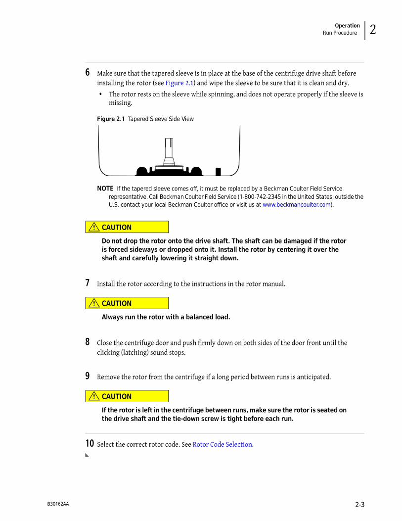
6 Make sure that the tapered sleeve is in place at the base of the centrifuge drive shaft before
installing the rotor (see Figure 2.1) and wipe the sleeve to be sure that it is clean and dry.
• The rotor rests on the sleeve while spinning, and does not operate properly if the sleeve is missing.
Figure 2.1 Tapered Sleeve Side View
NOTE If the tapered sleeve comes off, it must be replaced by a Beckman Coulter Field Service
representative. Call Beckman Coulter Field Service (1-800-742-2345 in the United States; outside the
U.S. contact your local Beckman Coulter office or visit us at www.beckmancoulter.com).
CAUTION
Do not drop the rotor onto the drive shaft. The shaft can be damaged if the rotor
is forced sideways or dropped onto it. Install the rotor by centering it over the
shaft and carefully lowering it straight down.
7 Install the rotor according to the instructions in the rotor manual.
CAUTION
Always run the rotor with a balanced load.
8 Close the centrifuge door and push firmly down on both sides of the door front until the
clicking (latching) sound stops.
9 Remove the rotor from the centrifuge if a long period between runs is anticipated.
CAUTION
If the rotor is left in the centrifuge between runs, make sure the rotor is seated on
the drive shaft and the tie-down screw is tight before each run.
10 Select the correct rotor code. See Rotor Code Selection.
B30162AA 2-3

Operation
Run Procedure
Entering Run Parameters
When the power is applied for the initial use (no previous runs), default values are displayed (see Figure 2.2). After the initial use, the parameters of the latest previous run are displayed when power is applied.
When run parameters for a rotor have been entered, as described below, they are retained in the centrifuge memory. The recalled program can then be used for the current run or altered as required. See Saving Settings.
Figure 2.2 Default Parameters on First-Time Use, Microfuge 20R shown
Menu Key Sequence
Pressing the MENU key starts the parameter change sequence. Repeatedly pressing the MENU key steps through parameter sequence. When the parameter units (rpm, rcf, m & s, soft-off,soft stop/start on, soft stop on) flash, press � or � to change that parameter. The entire parameter change sequence follows these steps:
1. Speed
a. in RPM
b. in RCF
2. Time in minutes and seconds
3. Temperature (for Microfuge 20R only)
4. Acceleration/Deceleration Options
a. Soft off
b. Soft-stop/start on
c. Soft-stop on
1. 15,000 rpm
2. 2 min duration
3. temperature: 20°C
4. no soft acceleration
B30162AA2-4
Operation
Run Procedure 2
Setting Run Speed
The RCF value is determined by the rotor geometry and speed. The RCF and speed values, therefore, depend on each other. If one of the two values is entered, the other value will be set automatically.
Centrifuge speed can be set for the maximum rated speed of the selected rotor. Either revolutions per minute (RPM) or relative centrifugal field (RCF) can be used to select speed. During centrifugation, the SPEED display indicates the actual run speed (RPM) of the rotor.
To set the speed
1 Press the MENU key until the speed unit flashes on the display.
• The RPM unit on the SPEED display flashes, indicating that the RPM can be entered (in 100-RPM increments) with the cursor keys.
• To enter the speed in RCF, press the MENU key again. The speed in RCF flashes.
• Program mode ends if no other keys are pressed within 15 seconds.
2 Press the � or � arrow key until the required RPM or RCF speed is displayed.
• The corresponding RCF is automatically calculated by the centrifuge, but the RPM value is displayed during the run.
• You can check the RCF during the run by pressing the � or � key while the centrifuge is running.
3 Press the MENU key until all screen functions stop flashing, to confirm the selection.
• The speed setting will be saved after approximately 20 seconds if no other key is pressed within this time period.
Setting Run Time
The run time is displayed in the middle line of the display. During centrifugation, the remaining run time is displayed. The run time of the centrifuge can be set at one-second intervals up to 99 minutes and 59 seconds.
Run time can be set for either a timed run or continuous operation.
Timed Run
Time can be set for up to 99 minutes and 59 seconds (if the seconds parameter entered exceeds 59, it is automatically converted into minutes). During centrifugation, the TIME display begins counting down when the rotor starts to spin and continues the count-down until deceleration begins. The TIME display shows the time remaining in the run, in minutes and seconds. When the time display reaches zero, the run ends.
B30162AA 2-5

Operation
Run Procedure
Continuous Run
During a continuous run, the run time of the centrifuge is unlimited and must be stopped manually. The centrifuge accelerates during the continuous run until the set speed is reached. During centrifugation the TIME display begins counting up, when the rotor starts to spin.
To set a timed run
1 Press the MENU key until the time unit flashes on the display.
Program mode ends if no other keys are pressed within 15 seconds.
2 Press the � or � cursor key until the required run duration is displayed. Pressing and holding
either key causes the parameter to change more rapidly.
3 Press the MENU key until all screen functions stop flashing, to confirm the selection.
The time setting will be saved after approximately 15 seconds if no other key is pressed within this time period.
To start a continuous run
1 Press the MENU key until the time unit flashes on the display.
Program mode ends if no other keys are pressed within 15 seconds.
2 Press the � cursor key until the display switches from 00:10 to --:--�.
After 99 minutes and 59 seconds, any additional run time will no longer be displayed, but the centrifugation will continue.
3 Press the MENU key until all screen functions stop flashing, to confirm the selection.
The time setting will be saved after approximately 15 seconds if no other key is pressed within this time period.
4 Close the centrifuge door and push firmly down on both sides of the door front until the
clicking (latching) sound stops.
5 Press the START/STOP key. The continuous run will start.
During centrifugation the TIME display begins counting up when the rotor starts to spin.
B30162AA2-6

Operation
Run Procedure 2
To stop a continuous run
1 Press the START/STOP key.
Deceleration begins immediately. The elapsed time shows during deceleration. The run ends.
Setting Run Temperature (Microfuge 20R refrigerated models only)
Run temperature can be set between –10 and +40°C. The typical operating range is from +2°C to 40°C, depending on the rotor and speed selected.
The temperature in the rotor chamber is displayed in the lower third of the centrifuge display. The display alternates between the set temperature and the actual temperature. The actual temperature is marked by the word “actual” in front of the temperature value.
NOTE The actual temperature flashes at 10 second intervals. When changing the temperature parameter,
be careful not to confuse the flashing of the actual temperature with the menu unit that also flashes.
NOTE Temperatures may vary slightly between instruments. If sample temperature is crucial, test
temperature settings on your instrument using water samples.
To set the run temperature
1 Press the MENU key until the temperature unit flashes on the display.
The TEMP°C display flashes, indicating that the temperature can be entered with the cursor keys.
Program mode ends if no other keys are pressed within 15 seconds.
2 Press the � or � cursor key until the required run temperature is displayed.
NOTE For runs at other than room temperature, refrigerate or warm the rotor beforehand for fast
equilibration.
3 Press the MENU key until all screen functions stop flashing, to confirm the selection.
The temperature setting will also be accepted and saved after approximately 15 seconds if no other key is pressed within this time period.
NOTE Opening the door turns refrigeration off. Closing the door restarts refrigeration.
B30162AA 2-7

Operation
Run Procedure
Rotor Code Selection
Select the installed rotor to allow for the correct RCF value to be selected and displayed.
NOTE All of the available rotors for the Microfuge 20 and Microfuge 20R have the same rated speed
of 15,000 RPMs.
To select the correct rotor
1 Press and hold the MENU key until the rotor unit flashes on the display.
2 Press the � or � cursor key until the correct rotor is displayed.
Rotor codes
• Code 1: Not used
• Code 2: FA241.5
• Code 3: FA241.5P
• Code 4: FA4x8.2P
• Code 5: FA361.5
• Code 6: Not used
3 Press the MENU key to confirm the selection.
The rotor code setting will be saved after approximately 15 seconds if no other key is pressed within this time period.
4 Install the rotor. See the specific rotor manual for complete information.
Precooling the centrifuge (20R refrigerated models only)
To maintain sample integrity during low temperature runs it is recommended to precool the empty rotor and instrument prior to the run. This centrifuge has a special program that precools the centrifuge under defined conditions.
NOTE Once the precooling program is loaded, the set temperature can only be set to values below the actual
temperature. If the limits of the setting range are reached during the setting process, the temperature
display flashes for approximately one second.
To precool the centrifuge
1 Press the PRECOOL key to load the precooling program. Precool on displays.
The display shows 1/3 of the maximum rotor speed and the corresponding RCF value. The runtime field indicates ‘�’ (continuous run). The set temperature cannot be higher than the actual temperature.
B30162AA2-8
Operation
Run Procedure 2
2 Press the START/STOP key.
Once the rotor reaches 1/3 of the maximum rotor speed (5000 RPM) and the precool temperature value is reached and remains stable for one minute, the program ends with the indication Precool OK.
NOTE If the precooling program is selected and then deselected without actually being started, the set
temperature will be reset to the old value. If, however, the precooling run is started, the limited set
temperature will also be used for the following runs, but it will not be saved in the program.
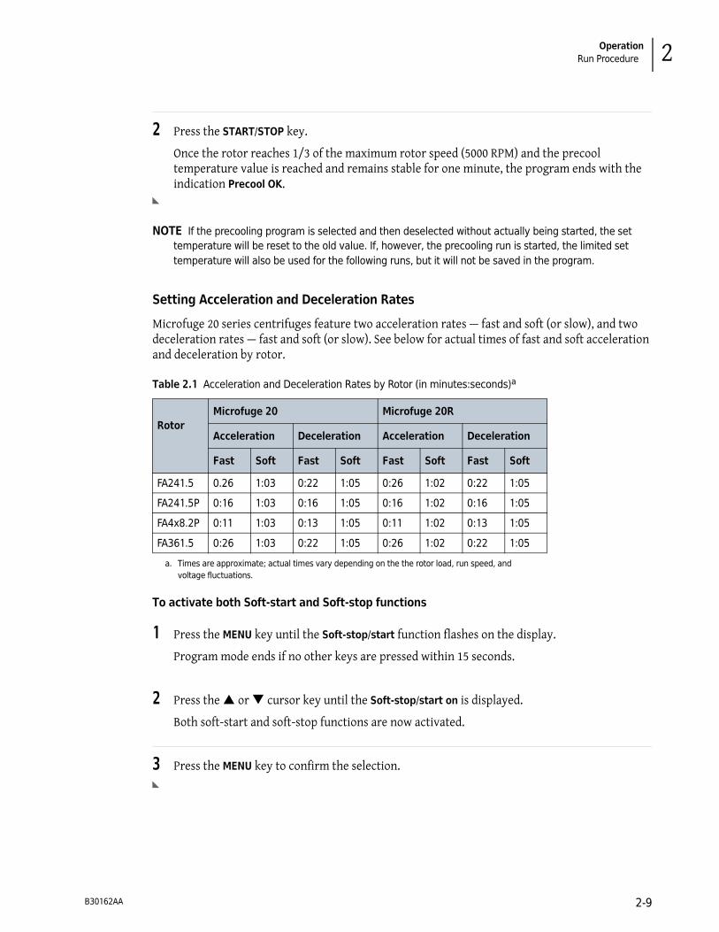
Setting Acceleration and Deceleration Rates
Microfuge 20 series centrifuges feature two acceleration rates — fast and soft (or slow), and two deceleration rates — fast and soft (or slow). See below for actual times of fast and soft acceleration and deceleration by rotor.
To activate both Soft-start and Soft-stop functions
1 Press the MENU key until the Soft-stop/start function flashes on the display.
Program mode ends if no other keys are pressed within 15 seconds.
2 Press the � or � cursor key until the Soft-stop/start on is displayed.
Both soft-start and soft-stop functions are now activated.
3 Press the MENU key to confirm the selection.
Table 2.1 Acceleration and Deceleration Rates by Rotor (in minutes:seconds)a
a. Times are approximate; actual times vary depending on the the rotor load, run speed, and
voltage fluctuations.
Rotor
Microfuge 20 Microfuge 20R
Acceleration Deceleration Acceleration Deceleration
Fast Soft Fast Soft Fast Soft Fast Soft
FA241.5 0.26 1:03 0:22 1:05 0:26 1:02 0:22 1:05
FA241.5P 0:16 1:03 0:16 1:05 0:16 1:02 0:16 1:05
FA4x8.2P 0:11 1:03 0:13 1:05 0:11 1:02 0:13 1:05
FA361.5 0:26 1:03 0:22 1:05 0:26 1:02 0:22 1:05
B30162AA 2-9
Operation
Run Procedure
To activate only the Soft-stop function
1 Press the MENU key until the Soft-stop/start function flashes on the display.
Program mode ends if no other keys are pressed within 15 seconds.
2 Press the � or � cursor key until the Soft stop on is displayed.
The soft-stop function is now activated.
3 Press the MENU key to confirm the selection.
To deactivate both Soft-start and Soft-stop functions
1 Press the MENU key until the Soft-stop/start function flashes on the display.
Program mode ends if no other keys are pressed within 15 seconds.
2 Press the � or � cursor key until the Soft off is displayed.
Both soft functions are now deactivated.
3 Press the MENU key to confirm the selection.
Starting a Run
The run can be started using the parameters in memory from a previous run, or using new or changed parameters that you enter using the procedures described above.
To start a run
1 Check that all parameters are correct and the door is closed and latched.
2 Press the START/STOP key.
• An actual set speed greater than the rotor’s maximum permitted speed, results in an error code and the centrifuge shuts down.
— See CHAPTER 3, Troubleshooting for information on error codes.
B30162AA2-10

Operation
Run Procedure 2
— Throughout the run, checks are made to ensure that the rotor does not exceed set speed.
• The SPEED display indicates the actual rotor speed in RPMs.
— The RCF can be displayed by pressing he � or � cursor key.
— This display also shows the time remaining in the run (or � and elapsed time for continuous operation).
• The TEMP display indicates the actual temperature of the rotor.
WARNING
Do not attempt to override the door interlock system while the rotor is spinning.
CAUTION
Do not lift or move the centrifuge while the rotor is spinning. Do not place items
on the centrifuge during operation.
Short Run (Quick Run) Function
During a short run, the centrifuge accelerates at a maximum rate until the set speed is reached. The short run function, accessed by pressing the QUICK RUN key, is used for short-duration runs as follows:
NOTE The Microfuge 20R Refrigerated centrifuge does not have a dedicated QUICK RUN button,
but pressing and holding the START/STOP button serves the same function.
• When the QUICK RUN key is pressed, the rotor accelerates at a maximum rate to the set speed and continues to spin as long as long as the QUICK RUN key is pressed. (The current run time, acceleration, and deceleration settings are overridden by the short run function.) When the QUICK RUN key is released, the rotor begins decelerating to 0 RPM using maximum deceleration.
• When the QUICK RUN key is pressed, the TIME display begins displaying the elapsed seconds. When the QUICK RUN key is released, the seconds stop accumulating.
• The centrifuge memory retains the parameters of the last run performed before the QUICK RUN key was pressed. At the end of a quick run, after the centrifuge door is opened and closed the previous run parameters are displayed.
To perform a quick run on the non-refrigerated Microfuge 20
1 Close the centrifuge door and push firmly down on both sides of the door front until the
clicking (latching) sound stops.
2 For the Microfuge 20, press and hold the QUICK RUN key.
The message Short Run and the duration of the quick run is displayed.
B30162AA 2-11

Operation
Run Procedure
3 Release the QUICK RUN key.
• When the QUICK RUN key is released, the centrifuge decelerates at maximum rate to a standstill.
• After the quick run and the centrifuge has come to a complete stop, the door unlocks automatically and the program that was set beforehand is displayed again.
To perform a quick run on the refrigerated Microfuge 20R
1 Close the centrifuge door and push firmly down on both sides of the door front until the
clicking (latching) sound stops.
2 For the Microfuge 20R, press and hold the START/STOP key.
The message Short Run and the duration of the quick run is displayed.
3 Release the START/STOP key.
• When the START/STOP key is released, the centrifuge decelerates at maximum rate to a standstill.
• After the quick run and the centrifuge has come to a complete stop, the door unlocks automatically and the program that was set beforehand is displayed again.
Changing Parameters During a Run
While a run is in progress, speed, time and temperature (Microfuge 20R only) run parameters can be altered without stopping the run. Run duration can also be changed from continuous to a specified time period, or from a specified time period to continuous.
NOTE The deceleration rate cannot be changed after deceleration starts.
To change the speed during a run
1 Press the MENU key until the desired speed function flashes on the display.
• The last digit on the SPEED display flashes, indicating that the RPM or RCF can be raised or lowered with the cursor keys.
2 Press the � or � cursor key until the required RCF or RPM is displayed.
The new parameter take effect immediately.
B30162AA2-12
Operation
Run Procedure 2
To change the run time during a run
1 Press the MENU key until the time function flashes on the display.
• The last digit on the TIME display flashes, indicating that the time can be raised or lowered with the cursor keys.
2 Press the � or � cursor key until the required run time is displayed.
The new parameter takes effect immediately.
NOTE If the run time is changed during the run, the centrifuge will run for the entire new time and will
disregard the previous runtime that has already elapsed.
To change the temperature during a run (Microfuge 20R only)
1 Press the MENU key until the temperature function flashes on the display.
• The last digit on the TEMPERATURE display flashes, indicating that the temperature can be raised or lowered with the cursor keys.
2 Press the � or � cursor key until the required temperature is displayed.
The new parameter takes effect immediately.
Stopping a Run
A timed run ends automatically when the TIME display counts down to zero.
To stop a run in progress
1 Press the START/STOP key for normal deceleration or the deceleration selected for the run.
2 After the rotor stops spinning, press the OPEN key to release the door latches, then open the door.
NOTE For Microfuge 20R refrigerated centrifuges: To prevent chamber icing, use a sponge to wipe
condensation out of the chamber bowl between runs.
B30162AA 2-13
Operation
Unloading
Unloading
NOTE When you remove the rotor, make sure that the tapered sleeve from the centrifuge drive shaft
does not come out with the rotor. If the tapered sleeve is inside the rotor drive hole, call
Beckman Coulter Field Service at 1-800-742-2345 (U.S.A or Canada); outside the U.S. contact your local
Beckman Coulter office or visit us at www.beckmancoulter.com).
After completing a run, unload the rotor following the instructions in the applicable rotor manual.
CAUTION
If disassembly reveals evidence of leakage, you should assume that some fluid
escaped the rotor. Apply appropriate decontamination procedures to the
centrifuge and accessories.
Summary of Run Procedures
For runs at other than room temperature, refrigerate or warm the rotor beforehand for fast equilibrium. For low-temperature runs, precool the centrifuge by running a 30-minute cycle (with a precooled rotor installed) at the required temperature with the speed set at 2000 rpm.
1 Press the POWER switch to on (I).
a. Open the centrifuge door (press the OPEN key and lift the door up).
2 Make sure that the tapered sleeve is in place at the base of the centrifuge drive shaft before
installing the rotor.
• The rotor does not operate properly if the sleeve is missing.
3 Install the rotor according to the instructions in the applicable rotor manual.
CAUTION
Always run the rotor with a balanced load.
4 Close the centrifuge door and push firmly down on both sides of the door front until the
clicking (latching) sound stops.
B30162AA2-14

Operation
Summary of Run Procedures 2
5 Enter run parameters:
• Set run speed — MENU until RPM or RCF displays, use � or � until correct speed displays.
• Set run duration — MENU until time displays, use � or � until correct time displays.
• Set run temperature (Microfuge 20R only) — MENU until temperature displays, use � or � until correct temperature displays.
• Set acceleration/deceleration — MENU until the Soft-stop/start on, soft-stop on, or soft off
displays, use � or � until correct deceleration displays.
6 Check that all parameters are correct and the door is shut and latched, then press the
START/STOP key.
WARNING
Never attempt to override the door interlock system while the rotor is spinning.
CAUTION
Do not lift or move the centrifuge while the rotor is spinning.
7 Wait for the set time to count down to zero, or end the run by pressing or holding the
START/STOP key.
8 After the rotor stops spinning, press the OPEN key to release the door latch; open the door.
9 Unload the rotor according to instructions in the applicable rotor manual.
CAUTION
If disassembly reveals evidence of leakage, you should assume that some fluid
escaped the rotor. Apply appropriate decontamination procedures applied to the
centrifuge and accessories.
B30162AA 2-15

Operation
Saving and Using Programs
Saving and Using Programs
The program is used to save or load certain recurring settings of the centrifuge. Ten separate programs can be saved and reused.
NOTE The precooling program does not occupy any storage location and cannot be deleted. It is used only
to cool the centrifuge without vessels. See Precooling the centrifuge (20R refrigerated models only).
Saving Settings
The following parameters that are set to be run can be saved as part of a reusable program:
• Speed
• Run time
• Temperature (Microfuge 20R only)
• Acceleration
• Deceleration
• Rotor type/code
To save settings into a program
1 Press the PROG key.
2 Press the � or � cursor key to scroll and select an unused program number.
The display Prog ## flashes (# represents numbers 01 through 10).
NOTE Scrolling through the programs causes the parameters of each program to display.
NOTE Program numbers that are already occupied will be overwritten with the current data.
NOTE The programs that are not in use display the default settings. See Entering Run Parameters for
the default settings.
3 Using the MENU key and the � or � cursor keys, change speed, time, temperature, and/or
acceleration parameters. See Entering Run Parameters for details.
4 Press the MENU key to confirm the selections and the program. The program is saved.
B30162AA2-16

Operation
Saving and Using Programs 2
To run a saved program
1 Press the PROG key.
2 Press the � or � cursor key to scroll and select the program number to be run.
3 Press PROG until Prog ## stops flashing.
4 Close the centrifuge door and push firmly down on both sides of the door front until the
clicking (latching) sound stops.
5 Press the START/STOP key.
To change a saved program
1 Press the PROG key.
2 Press the � or � cursor key to scroll and select the desired program number to be changed.
3 Using the MENU key and the � or � cursor keys, change speed, time, temperature, and/or
acceleration parameters.
4 Press the MENU key to confirm the selections and the program. The program is changed.
5 Close the centrifuge door and push firmly down on both sides of the door front until the
clicking (latching) sound stops.
6 Press the START/STOP key.
B30162AA 2-17

Operation
Saving and Using Programs
B30162AA2-18
CHAPTER 3
Troubleshooting
Introduction
This section lists possible malfunctions, together with probable causes and corrective actions required. Maintenance procedures are contained in CHAPTER 4, Care and Maintenance. For any problems not covered here contact Beckman Coulter Field Service.
NOTE It is your responsibility to decontaminate the centrifuge, as well as any rotors and accessories,
before requesting service by Beckman Coulter.
User Messages
If a problem occurs during operation, the rotor decelerates to a stop, an error code appears on the SPEED display. Such problems may result from incorrect input or from an equipment malfunction. Refer to Table 3.1 to determine the cause of the problem and recommended actions. If you are unable to correct the problem, call Beckman Coulter Field Service. To help diagnose and correct the problem, gather as much information about the situation as you can:
• Write down the error number that appears on the display.
• Note the operating situation when the error occurred (rotor in use, speed, load type, etc.).
• Note any unusual environmental and/or operating conditions (ambient temperature, voltage fluctuations, etc.).
• Add any other information that may be helpful.
Malfunctions are indicated by error messages with a number in the speed/RCF display. See Figure 3.1 for an example.
B30162AA 3-1

Troubleshooting
User Messages
Figure 3.1 Error message example
In the event of a fatal error (for example, a defective door lock), a certain safety time will be counted down on the display. During this time, ERR and SAFE flash alternately on the display. When the time is up, OFF will be displayed.
CAUTION
Do not switch the centrifuge off until the word ‘OFF’ is displayed! This is necessary
to ensure that the rotor is at a complete standstill.
To clear the problem or error
1 Eliminate the source of the problem (see Table 3.1 and Table 3.2 below).
2 Press the door key to acknowledge and clear the error message.
B30162AA3-2

Troubleshooting
User Messages 3
Table 3.1 Error Message Chart
Error Number Problem Recommended Action Explanation
1 through 9, System error After rotor comes to a complete
stop, turn the power off (O),
then back on (I) to reset.
All of these errors stop
the centrifuge or
cause it to decelerate
brakeless.
10 through 19, Speedometer error After rotor comes to a complete
stop, turn the power off (O),
then back on (I) to reset.
20 through 29 Motor error Turn the power off (O). Ensure
ventilation.
30 through 39 EEPROM error After rotor comes to a complete
stop, turn the power off (O),
then back on (I) to reset.
Errors 34, 35 and 36
will cause the
centrifuge to stop;
Errors 37 and 38 will
not cause the
centrifuge to stop,
these errors will only
return error messages.
40 through 45 Temperature error
(applies only to
Microfuge 20R
refrigerated
centrifuges)
• Allow to slow down
• Power off
• Allow to cool down
• Provide better ventilation
46 through 49 Imbalance error • Allow to slow down
• Power off
• Allow to cool down
50 through 59 Door error • Press door key
• Close door
• Remove foreign matter
from the opening of the
door lock device
Errors 50 and 51 will
cause the centrifuge
to stop.
60 through 69 Process error • Allow to slow down
• Cycle power
“With error 60
message “power
failure during run”,
with error 61, the
message “stop after
power on”
70 through 79 Communication error • Allow to slow down
• Cycle power
B30162AA 3-3
Troubleshooting
User Messages
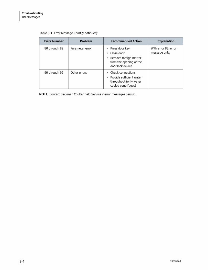
NOTE Contact Beckman Coulter Field Service if error messages persist.
80 through 89 Parameter error • Press door key
• Close door
• Remove foreign matter
from the opening of the
door lock device
With error 83, error
message only.
90 through 99 Other errors • Check connections
• Provide sufficient water
throughput (only water
cooled centrifuges)
Table 3.1 Error Message Chart (Continued)
Error Number Problem Recommended Action Explanation
B30162AA3-4
Troubleshooting
Other Possible Problems 3
Other Possible Problems
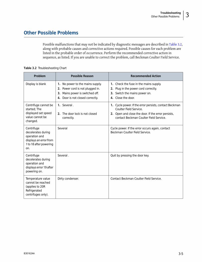
Possible malfunctions that may not be indicated by diagnostic messages are described in Table 3.2, along with probable causes and corrective actions required. Possible causes for each problem are listed in the probable order of occurrence. Perform the recommended corrective action in sequence, as listed. If you are unable to correct the problem, call Beckman Coulter Field Service.
Table 3.2 Troubleshooting Chart
Problem Possible Reason Recommended Action
Display is blank 1. No power to the mains supply.
2. Power cord is not plugged in.
3. Mains power is switched off.
4. Door is not closed correctly.
1. Check the fuse in the mains supply.
2. Plug in the power cord correctly.
3. Switch the mains power on.
4. Close the door.
Centrifuge cannot be
started; The
displayed set speed
value cannot be
changed.
1. Several .
2. The door lock is not closed
correctly.
1. Cycle power. If the error persists, contact Beckman
Coulter Field Service.
2. Open and close the door. If the error persists,
contact Beckman Coulter Field Service.
Centrifuge
decelerates during
operation and
displays an error from
1 to 18 after powering
on.
Several Cycle power. If the error occurs again, contact
Beckman Coulter Field Service.
Centrifuge
decelerates during
operation and
displays error 19 after
powering on.
Several . Quit by pressing the door key.
Temperature value
cannot be reached
(applies to 20R
Refrigerated
centrifuges only).
Dirty condenser. Contact Beckman Coulter Field Service.
B30162AA 3-5

Troubleshooting
Accessing the Centrifuge in Case of Power Failure
Accessing the Centrifuge in Case of Power Failure
If the facility power fails only momentarily, the centrifuge resumes operation when power is restored and the rotor returns to set speed. However, if the rotor comes to a complete stop the centrifuge run must be restarted when the power is restored. In the event of an extended power failure, you may have to trip the door-locking mechanism manually to remove the rotor and retrieve your sample.
WARNING
Any maintenance procedure requiring removal of a panel exposes the operator to
the possibility of electrical shock and/or mechanical injury. Therefore, turn the
power off and disconnect the instrument from the main power source by removing
the Mains (power) plug from the outlet receptacle and refer such maintenance to
qualified service personnel.
To gain emergency access the centrifuge
1 Turn the power switch to off (O) and disconnect the power cord from the main power source
by removing its power plug from the receptacle.
WARNING
Never attempt to override the door interlock system while the rotor is spinning.
DANGER
Never try to slow or stop the rotor by hand.
2 Make sure that the rotor is not spinning.
CAUTION
Do not proceed if there is any sound or vibration coming from the drive.
3 Remove the plug from the front panel. See Figure 3.2.
B30162AA3-6

Troubleshooting
Accessing the Centrifuge in Case of Power Failure 3
Figure 3.2 Removing the Emergency Access Plug
4 Insert the supplied 4 mm (P/N B33985) Allen wrench horizontally into the hole and turn it
counterclockwise until it stops. You should hear the door lock release. See Figure 3.3.
NOTE If the door is opened via the emergency door release system during a centrifuge run, the
centrifuge will be switched off immediately and decelerate with no brake.
Figure 3.3 Manually releasing the door lock with the Allen wrench
5 Reinsert the emergency access plug.
1. Emergency access plug and position of the opening for the
emergency door release
1. Manual release of the door lock
B30162AA 3-7

Troubleshooting
Accessing the Centrifuge in Case of Power Failure
B30162AA3-8

CHAPTER 4
Care and Maintenance
Introduction
For maintenance not covered in this manual, contact Beckman Coulter Field Service. User messages are discussed in CHAPTER 3, Troubleshooting. Refer to the applicable rotor manual and to Chemical Resistances (publication IN-175) for instructions on the care of rotors and their accessories.
NOTE It is your responsibility to decontaminate the centrifuge, as well as any rotors and accessories, before
requesting service by Beckman Coulter Field Service.
WARNING
Any maintenance procedure or servicing of this equipment that requires removal
of any covers can expose parts which involve the risk of electric shock or personal
injury. Make sure that the power switch is off (O) and the centrifuge is
disconnected from the main power source by removing the Mains (power) plug
from the outlet receptacle and refer such servicing to qualified service personnel.
Do not use alcohol or other flammable substances in or near operating
centrifuges.
WARNING
Risk of personal injury or contamination. If you do not properly shield yourself
while performing service, maintenance, and troubleshooting procedures, residual
fluids in the instrument could injure or contaminate you. Beckman Coulter
recommends barrier protection, such as appropriate safety glasses, lab coat, and
gloves, be worn throughout the performance of service, maintenance, and
troubleshooting procedures to avoid contact with cleaners and/or residual fluids
in the instrument.
The centrifuge, rotor and accessories are subject to high mechanical stresses. Thorough and diligent maintenance performed by the user extends the service life of the centrifuge and prevents premature failure.
NOTE If corrosion or other damage occurs due to improper care, the manufacturer cannot be held liable or
subject to any warranty claims.See the Beckman Coulter, Inc. Microfuge 20 Series Centrifuge Warranty.
B30162AA 4-1

Care and Maintenance
Maintenance
Maintenance
Preventive Maintenance
The following procedures should be performed regularly to ensure continued performance and long service life of the centrifuge.
1 Regularly inspect the interior of the rotor chamber for accumulations of sample, dust, or
glass particles from broken sample tubes.
a. Clean as required (see Cleaning, below), as these accumulations can result in rotor vibrations.
2 Regularly check the air intake and exhaust vents for obstructions.
a. Keep vents clear and clean.
3 To prevent the rotor from sticking, lubricate the drive shaft with Spinkote at least once a
month, and after each cleaning.
Cleaning
Frequent cleaning is recommended to prolong the life of the centrifuge. Always clean up spills when they occur to prevent corrosives or contaminants from drying on component surfaces.
NOTE Before using any cleaning or decontamination methods, except those recommended by the
manufacturer, users should check with the manufacturer that the proposed methods will not damage the
equipment.
1 To prevent accumulations of sample, dust, and/or glass particles from broken sample tubes,
keep the interior of the rotor chamber clean and dry by frequent wiping with a cloth or paper towel.
2 Clean the drive shaft, shaft cavity, threads, and the tie-down screw at least once a week using a
mild detergent such as Solution 555 and a soft brush.
a. Dilute the detergent with water (10 parts water to 1 part detergent).
b. Rinse thoroughly and dry completely.
c. Lubricate the drive shaft with Spinkote after cleaning.
B30162AA4-2

Care and Maintenance
Cleaning 4
3 Wash the bowl using a mild detergent such as diluted Solution 555.
a. Rinse thoroughly and dry completely.
b. If a cleaning solution other than Solution 555 is used, consult Chemical Resistances (publication IN-175) or contact the cleaning-solution vendor to verify that the solution will not damage the centrifuge.
4 Clean the centrifuge case and door by wiping with a cloth dampened with diluted Solution 555.
Dilute the detergent with water (10 parts water to 1 part detergent). Do not use acetone or other solvents.
� If the centrifuge has been contaminated with toxic, radioactive or pathogenic substances, clean the rotor chamber immediately with a suitable decontamination agent (depending on the type of contamination).
WARNING
Risk of personal injury or contamination. If you do not properly shield yourself
while performing service, maintenance, and troubleshooting procedures, residual
fluids in the instrument could injure or contaminate you. Beckman Coulter
recommends barrier protection, such as appropriate safety glasses, lab coat, and
gloves, be worn throughout the performance of service, maintenance, and
troubleshooting procedures to avoid contact with cleaners and/or residual fluids
in the instrument.
� Immediately rinse off the rotor, buckets or accessories under running water if they have come into contact with any liquids that may cause corrosion. Use a brush for test tubes to clean the bores of angle rotors. Turn the rotor upside down and allow it to dry completely.
� Clean the accessories outside the centrifuge once per week or preferably after each use. Adapters should be removed, cleaned and dried.
� If the rotors or accessories have been contaminated with toxic, radioactive or pathogenic substances, clean them immediately with a suitable decontamination agent (depending on the type of contamination). Take suitable precautions for your own safety if there is a risk of toxic, radioactive or pathogenic contamination.
� Dry accessories with a soft cloth or in a drying chamber at approximately 50°C.
� The chemical resistance of plastic decreases with rising temperatures. If solvents, acids or alkaline solutions have been used, clean the plastic accessories thoroughly.
� Aluminum parts are especially susceptible to corrosion. Avoid the use of cleaning agents that contain acid or that are alkaline on aluminum parts.
� Microfuge 20R refrigerated units only: Vacuum the vents once every six months.
B30162AA 4-3

Care and Maintenance
Decontamination
Decontamination
If the centrifuge and/or accessories are contaminated with radioactive or pathogenic solutions, perform appropriate decontamination procedures. Refer to Chemical Resistances (IN-175) to be sure the decontamination method will not damage any part of the centrifuge.
Sterilization and Disinfection
The centrifuge is finished with urethane paint. Ethanol (70%) may be used on this surface. See Chemical Resistances for more information regarding chemical resistance of centrifuge and accessory materials.
CAUTION
Ethanol is a flammability hazard. Do no use it in or near operating centrifuges.
While Beckman Coulter has tested these methods and found that they do not damage the centrifuge, no guarantee of sterility or disinfection is expressed or implied. When sterilization or disinfection is a concern, consult your laboratory safety officer regarding proper methods to use.
Storage and Transport
Storage
Before storing a centrifuge for an extended period, return it to its original shipping container to protect it from dust and dirt. Reinsert the shipping foam (removed at time of centrifuge installation) into the chamber, making sure the drive shaft is stabilized in the hole in the foam. Temperature and humidity conditions for storage should meet the environmental requirements described in the specifications given in CHAPTER 1, Description.
The centrifuge can be stored in its original packaging for up to one year.
• Store the centrifuge only in dry rooms.
• The storage temperature must be above –20°C.
• If the centrifuge needs to be stored for more than one year or needs to be shipped overseas, contact Beckman Coulter Customer Service.
Notes on Transport
• When lifting the centrifuge always reach under the centrifuge from the side.
• Use suitable packaging and, if possible, use the original packaging.
• Retain the packaging for possible future transport of the centrifuge.
B30162AA4-4

Care and Maintenance
Supply List 4
Returning a Centrifuge
Before returning a centrifuge or accessory for any reason, prior permission must be obtained from Beckman Coulter, Inc. Contact your local Beckman Coulter office to obtain the authorization form and for packaging and shipping instructions.
To protect our personnel, it is the customer’s responsibility to ensure that all parts are free from pathogens and/or radioactivity. Sterilization and decontamination must be done before returning the parts.
All parts must be accompanied by a signed note, plainly visible on the outside of the box, stating that they are safe to handle and that they are not contaminated with pathogens or radioactivity. Failure to attach this notification will result in return or disposal of the items without review of the reported problem.
Supply List
Contact Beckman Customer Service or visit www.beckmancoulter.com for information about ordering parts, supplies, and publications. For your convenience, a partial list is given below.
Refer to the applicable rotor manual for materials and supplies needed for rotors.
Replacement Parts
Other
NOTE For MSDS information, go to the Beckman Coulter website at www.beckmancoulter.com.
Description Part Number
Rotor tie-down screw 365806
T-handle wrench 365636
Allen wrench B33985
Description Part Number
Spinkote lubricant (2 oz) 306812
Silicone vacuum grease (1 oz) 335148
Solution 555 (1 qt) 339555
B30162AA 4-5

Care and Maintenance
Supply List
B30162AA4-6
APPENDIX A
Installation
Introduction
This chapter contains instructions for installing and connecting the centrifuge. Check that required clearances and electrical power are available.
WARNING
Risk of personal injury. Each centrifuge weighs 13 kg/29 lb (nonrefrigerated
model) or 32 kg/71 lb (refrigerated model.) DO NOT attempt to lift or move one of
them without assistance from a lifting device or another person.
Installing the Instrument
WARNING
Risk of fire. Do not place the centrifuge near areas containing flammable reagents
or combustible fluids. Vapors from these materials could enter the centrifuge air
system and be ignited by the motor.
WARNING
Maintain a 30 cm (12 in) clearance envelope around the centrifuge while it
is running. No persons should be within this clearance boundary while the
centrifuge is operating. Do not handle or store hazardous materials within the
30 cm (12 in) area surrounding the centrifuge.
Considerations to make before installation
• Operate the centrifuge only in closed and dry rooms.
• All of the energy supplied to the centrifuge is converted into heat and emitted to the ambient air.
• Ensure sufficient ventilation.
• Allow at least a 30 cm envelope around all sides of the centrifuge so that the vents in the centrifuge remain fully effective.
B30162AA A-1

Installation
Installing the Instrument
• Do not subject the centrifuge to thermal stress. For example, do not position the centrifuge near a source of heat.
• Do not position the centrifuge where it receives direct sunlight (UV radiation).
• The table or bench that the centrifuge is installed on must be stable and have a solid, flat surface.
• After moving the centrifuge from cold to warmer rooms, condensation may collect inside the centrifuge. It’s important to allow at least 24 hours for drying before using the centrifuge again.
To install the centrifuge
1 The centrifuge ships in a cardboard box. For easy access, remove the top of the box, the foam
insert on top of the centrifuge, and then the upper part (sides) of the box and set them aside.
a. Then, with the help of another person, move the centrifuge to its final position.
• (Note the warning above regarding centrifuge weight.)
2 Position the centrifuge on a level surface, such as a sturdy table or laboratory bench that is able
to support the weight of the centrifuge and resist vibration.
• Refer to Microfuge 20 Nonrefrigerated Model Specifications or Microfuge 20R Refrigerated Model Specifications in CHAPTER 1 for weight.
a. Make sure that the centrifuge front feet are fully supported on the table.
b. Locate the centrifuge in an area with sufficient ventilation to allow for heat dissipation.
c. Check that there are 30 cm (12 in.) clearances at the sides of the centrifuge to ensure sufficient air circulation.
Dimensions are shown in Figure A.1 or Figure A.2.
The centrifuge must have adequate air ventilation to ensure compliance to local requirements for vapors produced during operation.
For ambient temperature ranges see Microfuge 20R Refrigerated Model Specifications and Microfuge 20 Nonrefrigerated Model Specifications.
NOTE During transport between areas with varying temperatures, condensation may occur inside
the centrifuge. Allow sufficient drying time before running the centrifuge.
B30162AAA-2

Installation
Electrical Requirements A
Electrical Requirements
See the Microfuge 20 Nonrefrigerated Model Specifications or Microfuge 20R Refrigerated Model Specifications in CHAPTER 1 for centrifuge electrical requirements.
Make sure the voltage and frequency imprinted on the name rating plate affixed to the back of the centrifuge agree with the line voltage and frequency of the outlet used. Refrigeration does not function properly if the frequency [Hz] does not match the name rating plate. Plug in both ends of the centrifuge power cord. If there is any question about voltage, have a qualified service person measure it under load while the drive is operating.
A 1.8-m (6-ft) power cord with grounded plug is supplied with the centrifuge. Make sure that the matching wall outlet is located near the centrifuge and is easily accessible.
NOTE The power plug serves as the Disconnecting Device and must remain easily accessible.
Figure A.1 Dimensions of the Non-Refrigerated Centrifuge
B30162AA A-3

Installation
Electrical Requirements
Figure A.2 Dimensions of the Refrigerated Centrifuge
WARNING
To reduce the risk of electrical shock, this equipment uses a three-wire electrical
cord and plug to connect the centrifuge to earth-ground. To preserve this safety
feature:
• Make sure that the matching wall outlet receptacle is properly wired and
earth-grounded. Check that the line voltage agrees with the voltage listed on
the name rating plate affixed to the centrifuge.
• Never use a three-to-two wire plug adapter.
• Never use a two-wire extension cord or a two-wire non-grounding type of
multiple-outlet receptacle strip.
B30162AAA-4

Installation
Test Run A
Test Run
NOTE The centrifuge must be plugged in and the power switch turned to the on position (I) before the door
can be opened.
Beckman Coulter recommends that you make a test run to ensure that the centrifuge is in proper operating condition following shipment. See CHAPTER 2, Operation for instructions on operating the centrifuge.
After completing the test run, log on to www.beckmancoulter.com to register the centrifuge. This validates the centrifuge warranty and ensures that you receive any further information regarding new accessories and/or modifications as they become available.
B30162AA A-5

Installation
Test Run
B30162AAA-6

APPENDIX B
Table of Hazardous Substance’sName and Concentration
This materials declaration table (the Table of Hazardous Susbtance’s Name and Concentration) and the China RoHS Caution Label are to meet People’s Republic of China Electronic Industry Standard SJ/T11364-2006 “Marking for Control of Pollution Caused by Electronic Information Products” requirements.
B30162AA B-1

B30162AA
B-2 T
ab
le o
f Ha
za
rdo
us S
ub
sta
nce
’s N
am
e a
nd
Co
nce
ntr
atio
n
Series, Benchtop Centrifuge
质或元素
bstances Name
价铬
r6+
多溴联苯
PBBB
多溴二苯醚
PBDE
O O O
O O O
O O O
O O O
O O O
O O O
in this part is
.
有毒有害物质名称及含量的标识格式
Table of Hazardous Substance’s Name and Concentration
电子信息产品号码 EIP Part Number:
B31602
B31606
B31610
B31614
产品名称 Product Name: Microfuge 20
产品型号Product Model Number:
Microfuge 20 220V-240V/50 Hz
Microfuge 20 IVD 220V-240V/50 Hz
Microfuge 20R 220V-240V/50 Hz
Microfuge 20R IVD 220V-240V/50 Hz
部件名称
Component Name
有毒有害物
Hazardous Su
铅
Pb
汞
Hg
镉
Cd
六
C
印刷电路板组件 Printed Circuit Board Sub Assemblies O O O
电缆组件 Cable Sub Assemblies O O O
塑料部件 Plastic Parts O O O
钣金部件 Sheet Metal O O O
连接部件(螺丝,螺栓等) Hardware (screws, bolts, etc.) O O O
电源组件 Power Supply Sub Assembly O O O
O: 表示该有毒有害物质在该部件所有均质材料中的含量均在 SJ/T 11363-2006 标准规定的限量要求以下
X: 表示该有毒有害物质至少在该部件的某一均质材料中的含量超出 SJ/T 11363-2006 标准规定的限量要求
(企业可在此处,根据实际情况对上表中打“X”的技术原因进行进一步说明)
O: Indicates that the toxic or hazardous substances contained in all of the homogeneous materials for this part is
below the limit requirements in SJ/T 11363-2006.
X: Indicates that the toxic or hazardous substances contained in at least one of the homogeneous materials used
above the limit requirements in SJ/T 11363-2006.
(Enterprise may further provide in this box technical explanation for marking “X” based on their actual conditions)

Beckman Coulter, Inc.Microfuge 20 Series Centrifuge Warranty
Subject to the exceptions and upon the conditions specified below, Beckman Coulter agrees to correct, either by repair, or, at its election, by replacement, any defects of material or workmanship which develop within two (2) years after delivery of the Microfuge 20 Series centrifuge (the product), to the original Buyer by Beckman Coulter or by an authorized representative provided that investigation and factory inspection by Beckman Coulter discloses that such defect developed under normal and proper use.
Some components and accessories by their nature are not intended to and will not function for as long as one (1) year. A complete list of such components or accessories is maintained at the factory and at each Beckman Coulter District Sales Office. The lists applicable to the products sold hereunder shall be deemed to be part of this warranty. If any such component or accessory fails to give reasonable service for a reasonable period of time, Beckman Coulter will repair or, at its election, replace such component or accessory. What constitutes either reasonable service and a reasonable period of time shall be determined solely by Beckman Coulter.
Replacement
Any product claimed to be defective must, if requested by Beckman Coulter, be returned to the factory, transportation charges prepaid, and will be returned to Buyer with the transportation charges collect unless the product is found to be defective, in which case Beckman Coulter will pay all transportation charges.
Conditions
Beckman Coulter shall be released from all obligations under all warranties either expressed or implied, if the product(s) covered hereby are repaired or modified by persons other than its own authorized service personnel, unless such repair in the sole opinion of Beckman Coulter is minor, or unless such modification is merely the installation of a new Beckman Coulter plug-in component for such product(s).
Disclaimer
IT IS EXPRESSLY AGREED THAT THE ABOVE WARRANTY SHALL BE IN LIEU OF ALL WARRANTIES OF FITNESS AND OF THE WARRANTY OF MERCHANTABILITY AND THAT NEITHER BECKMAN COULTER, INC. NOR ITS SUPPLIERS SHALL HAVE ANY LIABILITY FOR SPECIAL OR CONSEQUENTIAL DAMAGES OF ANY KIND WHATSOEVER ARISING OUT OF THE MANUFACTURE, USE, SALE, HANDLING, REPAIR, MAINTENANCE, OR REPLACEMENT OF THE PRODUCT.
B30162AA Warranty-1

Beckman Coulter, Inc. Microfuge 20 Series Centrifuge Warranty
B30162AAWarranty-2
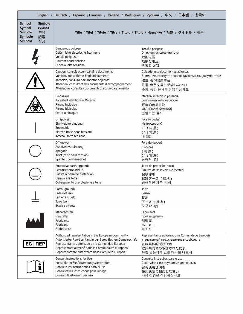
English / Deutsch / Español / Français / Italiano / Portugués / Русский / 中文 / 日本語 / 한국어
Symbol
Symbol
Simbolo
Symbole
Simbolo
Simbole
символ
符号
記号
상징
Title / Titel / Titulo / Titre / Titolo / Titulo / Название / 标题 / タイトル / 제목
Dangerous voltage
Gefährliche electrische Spannung
Voltaje peligroso
Courant haute tension
Pericolo: alta tensione
Tensão perigosaОпасное напряжение тока
危险电压危険な電圧위험한 전압
Caution, consult accompanying documents
Vorsicht, konsultieren Begleitdokumente
Atención, consulta documentos adjuntos
Attention, consultent des documents d'accompagnement
Attenzione, consulta i documenti di accompagnamento
Cuidado, ulta documentos adjuntos
Внимание, советует с сопроводительными документами
注意, 咨询附属单证
注意, 伴う文書に相談しなさい
주의, 동반 문서를 상담하십시오
Biohazard
Potentiell infektiösem Material
Riesgo biológico
Risque biologiqu
Pericolo biologico
Material infeccioso potencial
биологической опасности
可能的传染性物潜在的な感染性物質전염하는 물자
On (power)
Ein (Netzverbindung)
Encendido
Marche (mise sous tension)
Acceso (sotto tensione)
Fora (o poder)
На (мощности)
开 (电源)ン (電源)에 (힘)
Off (power)
Aus (Netzverbindung)
Apagado
Arrêt (mise sous tension)
Spento (fuori tensione)
Fora de (poder)
С (сила)(电源)ン (電源)떨어져 (힘)
Protective earth (ground)
Schutzleiteranschluß
Puesta a tierra de protección
Liaison à la terre
Collegamento di protezione a terra
Terra de proteção (terra)
Защитное заземление (земля)
保护接地保護アース (接地)방어적인 지구 (지상)
Earth (ground)
Erde (Masse)
La tierra (suelo)
Terre (sol)
Scarica a terra
Terra
Земли
接地アース (接地)지구 (지상)
Manufacturer
Hersteller
Fabricante
Fabricant
Fabbricante
Fabricante
производитель
制造商メーカー제조자
Authorized representative in the European Community
Autorisierter Repräsentant in der Europäischen Gemeinschaft
Representante autorizado en la Comunidad Europea
Représentant autorisé dans le Communauté européen
Rappresentante autorizzato nella Comunità Europea
Representante autorizado na Comunidade Européia
Утверженный представитель в сообществ
在欧共体的授权代表欧州共同体の承認された代表유럽 공동체에 있는 허가한 대표자
Consult Instructions for Use
Konsultieren Sie Anwendungsvorschriften
Consulte las instrucciones para el uso
Consultez les instructions pour l'usage
Consulti le istruzioni per uso
Consulte instruções para o uso
Советуйте с инструкциями для пользы
咨询使用说明书使用説明に相談しなさい사용 설명을 상담하십시오

© 2013 Beckman Coulter, Inc.
All Rights Reserved
www.beckmancoulter.com
Related Documents
Chemical Resistances for Beckman Coulter
Centrifugation Products
PN IN-175
Available in hard copy or electronic pdf by request.
Available at www.beckmancoulter.com