microfilmed from best - nasa · nome>on uuch l& )lapus to inmstigxtc t3e problem noticed in...
TRANSCRIPT

MICROFILMED
FROM B E S T
AVA i LA B 1 E
COPY
https://ntrs.nasa.gov/search.jsp?R=19930086918 2019-02-17T09:49:31+00:00Z


A' It is indecd possible, by ma= 01 the ~ a e c z y 0:: the "ideal
fluidA ta aake a fairly th~mugb imestk-tion of t3e actior; OS
eurrents Droducir~ 6c L i € t i q force. The question of the origin
cf such currents axxi t he cause of the resistance or C q CELL,
bow2ver, be sa3icfaStorily answered only by m a ~ c of Prandtlt s
u+,3eory of marenal layers-a The latter %fie6337 is a160 able Xci
explain the n%epus effectJU the nature of wrhich n s so tbomugh-
l y investimted at the G-ttingen Aerodynamic ZxperiEental Insti-
tute, that Flettncr rras straightaway &le to util ize Y-3 results
obtain& at d t t i r g c n for the propalsion of &ips.
Theoretical Sect io-tl.
Thanks to the successfui trial runs of the Flettner Rntor
ship %ickausn a hyirodynmdc phemneEon, shich, xitier the n a m e
of % a p s effectsq has b.Jec known for 3 long time, has 8uddexilg
acqcired practical importance.
been much discussed i n rciect i f ic literature aad has soEe5in;es
&en insorrectly presentd, it nay mt be amiss to state tbe
fac ts c l e a r l y in the present article.
Since this ?hemmenon has not
A short but very able description, of recent date, is m n - - From "Zeitsshzift des Vcreznes dmtechcr Inpriieure,n 'Jznuary 3,
1325, pp* 9-14.

3 U
The phaom,enon of the E a p u s effect canrjsts in tbe fact
that a ~evoIv+-ng body mving relatively t o t 5 e su r ro -d ing fluid
(air) i s subject& not onlv So drag ( i - e . , a force asti= in a
direction opposi%e to that c,' thc airzction of motion), bat zlso
to a lift, that i s to sey, a force acting at rigat -ingles to the
c,rectioo of mtian- The l i f t 5 s direct& tom& the side where
the re-ktive velocity betveczi thc fluid &-ad the sirface of the
revolving bcdy :s sLaIlest, ttat- is, t h e side where t3e peripn-
exal &-tion, sue to rotation, is ir? the dirzction s< f low of the C-
fluit? ( L e . , the sir), as i l lustrated i n Fiy. 1, i n xhich d b- &J
dicates the angular ve',oci+,y,
volving body, w the drag, and A the lifi.
v t>e formr6 velocity o€ the re-
apart from the experirnerits of Xapus, the effect rras con-
stantly noticed in thz form of tke deviation of a r t i l l c r y pro-
jectiles f r m their tn ie t ra jectory. Ir, f ac t , it m s t h i s pbe-

nome>on uuch l& )lapus to inmstigxtc t3e problem
noticed in the s t r a n ~ l p curved trajectory af temis axi other
halls usGd in p n c s [Fig. 2) (See LcrC €kyh2g?P s paper: "On
tke Irrsgular F l i g M of. a Tennis B a l l , " - "Scientific papers,"
It IELB alta
Qol- I, t o 344.)
Be%re r.? endeavor to eqlaia hoa the H a p s effect is pro-
awe?., it ai11 be w e l l to look a l i t t l e mre=cLosely into the
terms "liftc md uI!rwa an6 thi? causes producing thece forces.
If we &ve a body ; ~ i g . 1) a velocity of v, we =st, in
order t o sycrcome tbe drag V, produce, .aery seeon&, a power
equal Bo Fv. The lift A, on the other har?d, CCUC for TY) ex-
penaiture of energy, since it is at right angles t o v. In an
"ideal fluid,a i3 uhic5 there is no lose of ensr-, a body mving
at a uniform rate uould m e e t w i t h QO resistance, but there would
probably be a liftfng force.
nected with t h h l i f t fng force i n general, we can, therefore,
base OUT inquiries on the processes in an ideal f luid (i -eo , a f l u i d which, in flowing, loses none of its parer).
ne l 9 a n a great deal &out the connectSon betasen the f low and
In Qmestigathg the procesa con-
In this way,
the l i f t , but thit question as to how and why, in a given case,
t h i s particular flow should be cornected with the lift prduced,
still remaics u.riLs?JIswered.
In th2 case of an airplane having norm21 w i n g s with a sharp
trailing &go, knoaing, as rre do, that the fluid docs ,kjt flaw
zyouna s b z edges, wc can 685' maething abut t h e l i f t t o be ex- s

pectd.
sharp t x l q ~ is as yet not c l e a r l y k r ~ o m ~ t h i s insthod of r a s o n h g
fai ls , when the d y e is m t s ~ ~ a r p , tikt iforc or less sound-&.
SU?, since the re3son wny K ~ S liquid does m+ flog aroud
To enable us tc follon the discxssion in thc prcscrit essay
more clearly, lct us 3riefly,exa,aine the ;?roccssas p i p 5 03 in
lees1 f lulds, th? so-c;r.llej. "pc tzntial a126 then incpl re
into thc -crc c o p l e x cmses of drag s& l i f t , as c x p k i n d 5jy
For a'mdy to be subjected to a l i f t , 1: is necessary that
there shoul& be, r ) ~ an merag:, a higher Dressire 011 the lower
side than on tba ugex . Irnsmtch, howerzrr, as the pressure p
and the velocity v are connected with each other by the rela-
wbich . p denctes the density ef the f lg id ) , if there is a l i f t
at a l l , then the velocity must be, on zn axrerage, greater above
than below. - Following up this l ine of reacmtAng, w e find, that
the best pla-n i s to take the C i r c U k t i O n
I
r - as the 6ta3&ard for
t h i s difference in velocity, xhich we arrive at as follows:
After d-awing the l ine 8 (Fig. 3 ) , around the moving
body, w e assume tk t the velocity at a certain point of s is
v and that the component of 8 , , touching this ;mint in the di-
rectfon of the tangent to s, is W . The? tlie c i rcu la t ion is
nhcreby the i.nte%;Tal I i s to be coptiriucd clcay arcund thc 2
l ine . For the lift A, we the: Tet the sicrple equation (Kutta- Jf

- Sg&&ossky formula) s = i, v rl . Hcre again Q i; the density
borly; and i , thc: lcnsth of t k %oCy at right ansles to ';be
plane of the erawing. The c i r cu la t ion is assumed as coi,sta;3t.
thmuzaout t n e vhole length.
T e can i;;lz?.,gjne 2 current r;itn a - l i f t , as b z h g c o ~ o s e d of
two rations i i t h c n t lift. Ir, one of them t he c i r cu la t ion f is
0, but there ie the velocity V relative to the body a-t a s e a t
d i s t a n c e from it (Fig. 4). IF, t h e oIhez, kovmer, there is ocly
a circulat ion current I', but EO forward velcrcity e (Fig. 5)
Both cur rmts arc Fossible as potent ia l m t i o n s . Xow, i€ Be
sapcrposc t h e t ra curre-nts, I.c. if, a t cvery point, we combint.
<he two v e l o c i t i e s Tec tor ia l ly (like forcca i n a p a r a l l c l o g r m
of Zorces), we thcn once more g e t a p o t e c t i d motion, composed
of t he c i rculat ion I" of one niotian 2nd thc forward ve loc i ty T
of the other, resu l t ing i n a l i f t (Fig. 6) . The introducsion of the term :'circiilat,ion'' is w r y uzeful,
2 s an aid t;> t h e uix%erstarding of the connection betree2 t he
co-crse of thc flow ar,d t he l ift, but i t does not answer the ques-
t i o n as t o hog t h i s l ift is prodv-ccd. 3ltimately it redwcs t o
t h e qw.L%ion as to horn the %irculationl! is+prcr&ucd. Never tno
l c c s this me$hod can adwaiictj -as a l i t t l e . If t he f l u i d ( i . s . ,
c lea r t n a t the c i r c u l a t i o n mst be 0, since, of course, t h c
vc loc i ty throughout t h c cn t i r e length of 8 LE; 0. Then, if ~ J C

s e t the b a y i n motion, the E'ta3e oi t3e circulatioa c a , accord-
ing t o a l a w of hydrodynamics, undergo a change onXy when vorti-
ces o r eGCies Gtray outi'or in to +,ie ZOEE: ex iosod u2th4.n the
l i n e (Fig. 3) Irr this event, tile increase c-. decrmse i n the
cir+culatior: is exactly wal t o t h e sxpr 03 tbc circulation round
Of s
about the vo r t i ce s or edeiss corr;ing iz or goip.g ou t res>ectivelp,
(one direc-Lion of ro ta t ion t o be reckmed as positive, the oppo-
s i t e as n e e t i v e ) . We see, therefore, that the produc3on of a
c i r c u l a t i o n around a body sr-rrounded by a f luid which hitherto
has been a t rest, is pss ib le only tancn vortices or c d d i u arc
formed slmltaneously i n t he f luid. I n arr i5w.L f h i a this , as L,'
the very defi-ai+,ion implies, is an iqossibiltt3\ since, of
tmrse, the formation of 'vortices ar cddfcs is i&yarsbIy con-
nectcci w i t h loss of cnergy.
Srocesses which cause the formation Gf vortices or eddiee in
-- acvdal fluids
1.
We mist therefcrs n o m t & - ~ t o those
If a f lu id is set in motion by a di f fe rence i n pressure alotie,
a potent ia l motion is produced, as i n an ideal f luid. .
fluids, however, owing to their viscos i ty , there Ere add&, t o
the forts QI" ?ressre ? ( F i g . 7) shearing fo rces T, which
i m D z r t , a rotary motion to the p&rti;les of the @1uid and thus
produce eddies o r vor t ices .
Tihen the ve lcc i ty iricreascs a t r i g h t angles t o t h e d i r cc t ion of
t h e .i?-oi.r. Inside the i'luie t h e e f f e c t of these shearing forccs
is gcnezally of no consequence, since the v e h c i t y variationr;
a r e not very abrupt. I~O~:COVCXI, as we can provc, a3 long as thc
I n a c t u a l
ShearinfT forccs of t h i s kind appesr

ccrrent is of
erted ofi a particle of fluid (T, to T, i n F i g . 7 ) CoUlit6rbalm%
one anothsz. 0x1 the other hand, the egfect of these fofeas i s of
supreme importance, nhen the c z r e n t f i r ? W s past a firm wall or
surface,
potectial nature, the various ~ihearirig forces ex-
Ther?:. dt-hin a thin layer, there 3.s 2 transition from ,
the normal wirrent velocity t o zero ve loc fe on the mll ( F i g . 8)-
I+, is, thymefore, in th i s , the so-called "narginal lqrer," that
the viscosity, which d i s t i w i s h e s actual from idsal fluids,
plays an important part. .
In th i s layer marly a l l tbrree dhturb-
a m % l a v e their origin, yhich distingdish the f low of actual flu-
fds from a potential flow. Bs_Cax W k a8 twenty years ago,
Prandtl called attention to the imeportanco cf the ptocesses pfng
os within this marginal layer ani demonstrated their effee% by m e a of convincing experiments? The following remarks follow
close1.y the ori@nr3 arGments adduccd by Prsndtl.
quiries l e t us consider the f16.r around, a cylindrical body,
rrhich Interests us i n particular.
ever, apply d e 0 to bodies of other shapes.
In OUT in-
B e t of the argwcnb, how-
On the sidss of the cylinder (&om3 md below i n Flg. 4)
the lines of flm are more cl@selg crowdcd together. t'm else-
where.
s u l l e s t .
Here the velocity is the greatest anti +,he p r e s w e the
In a potential flow the velrrcjty is r e d u c ~ d axxi :ha c
pressure increases again. The kinetic energy of the ZPi3C ycrti-
d e s enables them to penetrate i n to the regiozr of hf.@or 2 - sure. In t h i s process, their velocity, under tts ~ ? ~ f I ' A C . S C ~

increasing pressure, i s retard* in precisely the sane measure
t i c l e of the xlazginal layar.
the r , o m l f lox outside t h i s lay;..
fore i-mi-<fizfZ,n_t- eneblc i t to penetrate into the zone of
higher prcswre- I t stops, before it gets tkerc, an3 r2vxfit"8
the Birection of its rrr>tLon. Howcrer, since new oargim layers
are consitatly flowing ou t of thc zone of lower pressme, mre
Zts v s b c i t y is lower tkan t h c t af
Its kicctic energy is t & r e
and mre margid-layer material E;.radua.lly aczumulates in the
region where the pressure i s incxeasing. This marginll-layer
material has two important pr3pcrties: P Its t o t s 1 enerr; (2 + 3 v2)
rest of the current.
1. is l ess than that of the
2. L t r ; indiwidual particles are rotstirrg.
The subsequent -stages i r s the developmcnt of the marginal
l s y e r accurmlatioas ore illustrate6 by Bigs. 9 to 11 (according
to experiments picture8 m d e by Prexdtl in 1904, and by
Rubach, at Prandtl's ifistitute i n 1913-14) The rnarsinal layer
-
material i s indicated by the stippled portiocs. When the mar-
ginal layer material ha8 bec'oae fa iz ly thick, i t i s carried
along by the ccrrent and f inal ly passes atvat i r r t h e form of vor-
t ices; whereupan the whole proceb6- is repealed. The eymnetry o f
t h e departing pairs of vortices is no5 stabte *and, consequsntly,
one vortex gets ahead of i t s conpanion. :;gr,,ce the mbscqient
f o r n x t i m Qf vort l icPs i s riot symmctrim1, but takcc 21acc d t o r -


peripheral notion of tbe cylinder i9 ir, the di-rection of She f l o w ,
LG acxglaal layer at all, or 0 5 l y a very .mcb tkiyx-er one, is
iar;rred- TXs zecpires muck =re t h e to zczunkte to %A& m CX-
teat, that ft carr f l o w off in the form of z vmtex. On tks oppo-
velocity, however, m e a n s t'ne fornation cf mre vorticss an6 53ce
versa. nt;: circula%ion, tkercfmsc, incrmsc-s - a t i L tkLe h f~u-
a c e aunterbalacces %he effec% of the rotation of the cyllngler

longer on t h i s sLie t Ln on f-ther. me;., it €fox of f , f%
has alredy acqnired, ca its uppcr sfde, a velocity which caxses-8
-etrong &ownmzrd gressue. On t'n* lower side, t3e up& dkviatior
of the ca-eet is much lese p ~ ~ m u n c a , because it parts company
with the cFlizder soonzr. On the whole, there is cansequentlp a
&omward daflection, ohich psduces an upward reactioc or lift.
T h k is still a third viewpoint, from ~ M c h we cau r e e d
the pro1 ;em.
der, I t s cnswsectiea f i&t ant--acted ezid tam expaadd, much
like P tube wit5 a cuDS-icted section ir; it.
As the =-aid ( L e m , %he air) flom past the cylin-
The piacess a% the
pofct, where the crose-se:tion e r g s azd mere velocity i s con- verted iE to pressure, is always attended tq- corisiderable l m ~ e s ,
* . e tp . _ the formation of nrt icec , eipecialhy wiien the expansion
t a k e s place rapidly, *ich is the a i s on the "-ax prtiorr of the
cylinder.
greatly increasH by the rotatim of the cy l ider , since feuerr
On one side the beneficial effezt of the expansion is
vortices are formed, and cpns*Qimtlp there id less loss 02 ener-
gy. Let LS imgine that ix a wind tmncl there are two constric-
tions side by side, th+ narrowest part of the constriction being
exactly of the same diameter in bot> cams, the ddening cf one
being a gentle slope (a i n F i g . L3) dt'a correspondingly ti@
efficieficy; the otter (b in F i g . 13), abrupt, with imor ef'ici-
ency. The Quantity of f lu id (eir) flowing thouah - the opeaing a
13
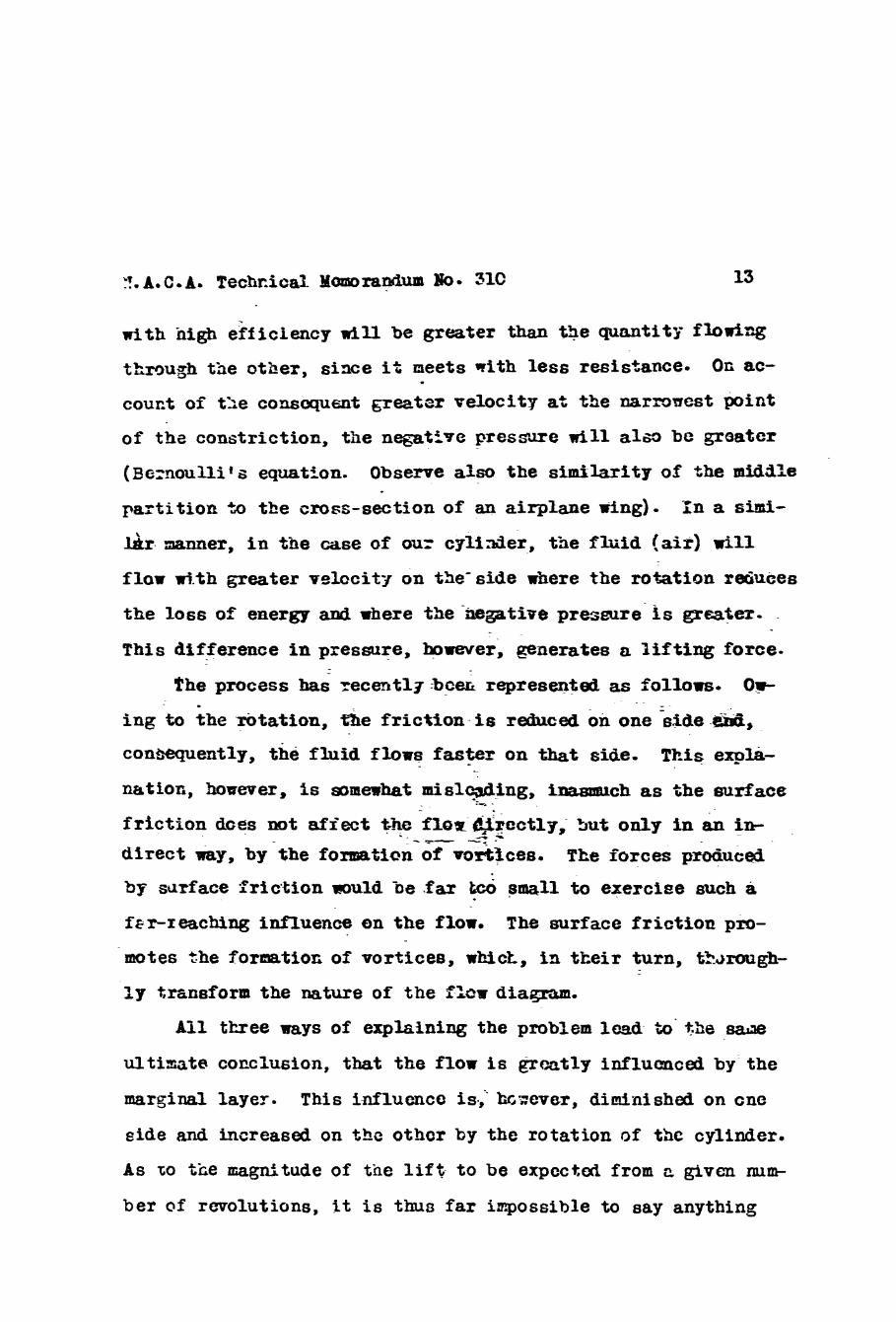
tkmu@ the other, s i x e i’; meets with less rer;is+,ance. O r ac-
couct of t L e corumquent greatsr velocity at the rzarmnest point
of the constriction, the negattfve pressure nil1 also be greater
(5cxoul l i t s equatfon.
partition ?XI tfre cross-section of an airplane ring).
Observe also the similarity of the midab In a s k i -
f l o w d . th greater velocity on the’sfde where the rotation raiuees
the loss of energy and where the kegative prffimre is gratia-
Phis dffference in pressure, however, generates a lifting force.
fhe process has recatlg-be- represented as follows- 01-
ing to the rotation, t3e friction i s reduced on one k d e m, con-ently, the fluid f l o w s faster on that side. This expla-
natior;, however, is s a m e a h a t mislcsding, inasmttcb as the surface --
direct way, by the formation of vorifces. by sclrface :friction mould be .far & small to exerciae such a
fEr-reaching influence on the flow.
The forces pm6uced
T h e surface friction pro-
motes the fornatiors of vortfces, whict, in their turn, tbraugh-
ly trsosform the nature of the f b a diaqrstm.
A i l tkree ways of explaining the problem l a d to’ %be sam
ultimate C O E C ~ U G ~ O ~ , that the flow is greatly influenced by the
marginal layer. This influcncc is,‘ hcvevar, diminished on cnc
eide and increased on tbc othcr by the rotation of the cylinder.
A s to tke -@tude of the l i f t to be expcctd from c given mrw
ber of revolutions, I t i s thus far inpossible to say anything

def id te an tne basis of t3is t?eorp, since t h s mthenaticd eal- - ctilatiop of t-hs forms pmiuceb, by the seprztion ph6mmna, d+
extremely diffioilt. In t 3 i s coracctim, Z wuld l i k e to point
oEt t'hax, fr; the technical press, the ciicxllation is so i~e t i~es
statu!, on the basis of iacorrect conceptions, to be equal +a
the gerlphcral vcl0cit)t m l t i p l i e d 37 t k circvmfcrcncc of the
cylizader, the l i f t being tkcc czlcihtal from 3 5 s product 3c-
cording t o S c h u ~ w 6 h - y ~ ~ fornuh. Tkrc is, horrcver, m justifi-
catinn fqr tkis purely a z b i t r c y m e t h c r L XCTOOVC.~, $he figures ._
The first eiperiornts, as ~lreaCy mentioned, were made by- :
the Beriin-pbgaicist tiagas, 13 1853- Thsy FZX& tlse exist- -

X - A s C . A s Technical Eenorandum NO. 310
the properties ~f a wing by the remective l i f t and drag coefficb-
P A = C, F xr2, and the d m g
- . The remltant force is
. In the above k a t i o n s F aeno-tes the *test projection
of thh ring mrface, p tne density of +be fluid iairj and V~
the ve-locity. For a good ting the highest attainable % is
about 1,2 t o 1-4. -. Unusual forms (slotted Kin@ and very highly
camber& aings) e v e vdlueG of % txp t o about 2. Lafay obtained4 . I a maxixium ca = 1.8 or cr = 2-4.
Cr. Wieselsberger, at the AemdyTnamic Exper5-menta3 Inrsti-'.utc
in dttingen, belonging to the Kai8er Bifaeln Gociety, attempted,
during the first years aftor the war, to fat'aom the &.~I-:IC efi'ect
by taking atact rneasurmerts. These eqcr;?rtents came t o nothing,
'5\
owing to technical difficulties, and were then- dr?pped, becmez
Dr.. Wiesclsberger left the Inst i tute . In 1923, an opportmity.
sa6 afforGed to carry oat the experiments n i t i a c h improved
means. Scveral small "igh-sped m9tors of comrat ive ly high
efficiency had been built at the Gttingen Exycrimental Ins t i tu te ,
t o &rive small proy>ellerc ori airplam mciels ~~spcni !cd fn thc
ooind tunnel f o r the purpose of taking meamrermnts, which pro-,cl-

lers had to he driven u d e z conditions approxiaatiq actaal COIF
dit ions 3s cZosely as pwsible- 8 Tkse rotors wcre hlgkly suita-
ble for drzvinz a cylirder zt high q~c;ed in tSe investigation of
the Yagnus effect. The dimeter of 3iicsc mtor9, in thcir p n s -
ent form, is 42 mn; lcngth, about 180 am; mrimum nizibcr of rem-
lutions, 30,Ccx) b . T . 3 . ; a3mt 1 =-- fhcsc motors arc map being .
b u i l t by t‘nc “Slektrosch=tltwerke B O G u i n &ttin.gen. For tbeo-
rc!tfcd. reasons, alreariy set forth, i t was to be expected that,
i n o@er to obtain a tpoaerful effect, peripheral velocititm
would be rapirai amimtiag to several tines t3c velocity cf the
rind. fioa if thc dianctcr of thc cylindor tic wind velocity w
*re to ’oc kept wit-d-n thc limits dcsira3le for tcc‘hnical rca-
sons, it m6 obvious $ha% the rcvokdtion rdmbcrs uoula hmic *Lo
B ;
be high. Tbcsc ncn motors aerc,. however, quite capable of ap -
plying them. Zwneer Bcteret rade use of this favonible oppor-
tunity to determine finally the-ragnitude of the 2iargn.m effect.
-The f i r s t experisental a2-!cratus was very siw+?s. - There was a
Rozxle 01: funnel 200 x 2330 mn2 i n cross-swtion (Fip. 14 and
15) -with two wooden d 1 s as extensions of t’re side walls ‘of the
funnel.’ Bctwczn t’hcsc tm d l s he f i t t cd‘a cylindzr a mm i - n
diameter, revolving on ball bearings azid driven frola outside
the rrclls by m e of the aforesaid high-speed motors.
air was blown out of the funnel against the cylinCer a t rmt , i t
flowed away behind the cylinder in a practically hoi izonta l di-
recfion.
men the
If, however, thc cyli-ndcr was rotatd (direct ion of

ro ta t ion as i-rrdica';eb ir, Fig. 14, K;lt ir the Liftiag force dircot-
shich can be easily cs l cuhtd by the las of ixrpilse mci since
this force can only have its origin in the cylimier, canclasions
couid be C r a m , as t o the rm,griitude of t'Ss force, froa the an-
gle 0: ief lcct icn (;fhicfi m s nearly 90 2 expcrigeot r c a u l t d ia an u~uxzxllg large l i f t , &out tbrec times
%-hat af a p o d 3jrplF.ne clw giviw the exact res ! l t s of these prelininrrry eqerime$s, as
c Bra th i s first crude
(<:a = 4) T3ere is no object in -L--.
they vere subseqcently repezted Tith irrrproved apparatus, tae re-
Glts bein!! e v s n jin Figs. 20 and 21. -
In order, hovievcr, to mcke q d t e sure that the dctcrilaation LI - of the lift fro% the dcflcction did aot lead to mng mn~ius-
lons, the *ole apparztus ( d l s , cylirder a motor) were fn- .-
G t a l l e d on a platfcrm b3lance in the 'cig vind tunriel of 4 n2
cross-secticn, at the Acrodynmic Experircmtal inst i tute , so fn2t
the lift mul& b-r! mzzsured. 3erc also the largo lift val-
ues wcre u3te ind .
These r e a l l y rcrx~r'cb3.e resi l ts were still unsatisfactory,
since the theory indiczted the poss ib i l i ty of o3tainirg far
greater l i f t ing forces (GI: = 4 n = 12.6). P,ltk.,ough it was t o be
expezted, on account of biaturbing influeaccs c o m e c t c d with the
forms%ion of vor t iccs :ad other rcamrls, that the maximam could
not be aatairied, ;;et the discrepancy vas too Cmat t o bc ex--

t h r d s in it, cho& th& the 1iftL-q force VELG conficed ctricfly
to t're middle porticn of the cylinder. Prandt l explain& this as
follows: Or; the suction s ide of
tiorally brgt? negatzve 'pzessure
ing force (H%th cy = o n, p-dn P
ca = 0, m n -XU be :3 L, v2).
tae cylinder there i s a?z e x e w
d-ae t o t h -msuallp greot lift-
W O G ~ C be - 15 va; with , ' . - c . ._
At the ends of the cylinder,
however, there i s zir-at - ordinary pressure, which is dram into
the negatfve przssure zona (Peg- 16)
auction o f the effect, by 4wing t h e s- effect as 2 tilick
interferes with the pro-
marginal. layer (Compc?re tke faregoizg cqXLpaation of the produce
The moden mlh, used i n the experiments, &mot prevent
the f l o w i ~ ~ in of outside air, since the marginal iayer 0x1 the - -
surface af these wcUa ia pcrtly drawn inw,.lrd towzrd the central
portion of the cylinder an& is partly separated from the w a l l s by
tae great differences i n pressure, thus emblirrg me outside air t o penetrate to the c y l i d e r ( F i g . 17).
c
swing , to this exte-.it, datained an insight into the condi- :-,
tions governing the process, i 5 becam possible t o dmise means
f o r effec-lly p r m e n b g the inflow of outside a i r , PraiiatL
suggested puttinz dtsks on the ends or' th&" cyliildcr, larger in
diaxetcr than the U t t e r aEd revolving vi th it (Fig. 18).
t o the ro ta ry motion, the mrgincl layer of them disks is tdb-
Wing

j e c t to awroxLm.tely tbe sape cor&i:iocs as t’3e marginal lazer
on tke smfsce sf the cylincier. Therefore, l i k e tha iatter, it
is not f3rccd to sexrate or, t 5 e s i c t ion sXe, but is acW2ly
hriveri outmud by the centrifugal force.
The subswpefit csporiocnts, carziecl out with a cylirdcr f i t -
t.eii with terminal Cieka, fully ccafiroed I’mndtl*s vfcws. The
lift incrwse t9
proximata3 tne theoretical maxirzm, that the differeace is no
c, = 5 (cr = 11). p h i s fiwre so clcsd-y a p / /
p r
longer s txange.
The disturbarice
inflow of air .$5 e the
m-:e -pronounced, the
ter. Xith very long
of_ the Sagnus eff e&, -caused by the la-;*-rsl
absence of t e i d n a 3 disks, b e c ~ s s a 3 . l the
shorter *e cp’ll-r?der is for a given dime- .
cylinders, the disturbs-me is relatively
smail and the terminal disks are r u t of such Teat inrpartance.
T h i s also explains why, at Gktir.Sm, we were able tc gez far
better resu’lts tW &fay, even without disks, since the cylinder
‘38ed by kfag was ahc-rtor tkin ours* A Ecbsequent t e s t , wdc
with a cylinder seek as ucod 5 y LaZay, conitirmd his rzsults.
9
.- As the result of thcse experiments, the ques-iAcn of the
Magnus effect &ad becn pra$tj.cally s O 1 P d , both 3 y clrperimnt and. - \
Eore .erfcct apparatus, in order t o bring tho results uq tc %he
high stardard of nzcwacy requked by the d t t i n g z n Icat.t,tW;;3.
-that time he was worki2s on the idea of replacin? the sai?s of a
shj: ;y rig?! Wing-shaped devices and vas having experiz9nts mJ8

for this puguse at the &ttir,gen Aer -Gynami~ Experimental .Irisfi-
tute- Yith his resm'kable icsight be immedia5ely recoipllzed the
-;yeciG cdhnificartce Crf these ne3 results for :lis pxr~3se of re-
placing the sstls of ships by 1 1 3 0 ~ miteklo devices. In tk? grcat
majority of cases, in which liftihg forces are used technically,
their production by m e a n s of the U g n ~ o effect mi133 require a
wry high revolution sped, irxolving, in its turn, such gwat
t i r d y w i p c l out. -
In tke case of a sailing ship, Kio coadi,tions arc wpeciallp
favorable.
efficiency are not high ( 5 t6 10 w'sec.-)
The wind velocitiae zequired t o produce the z m t i m i -
consequently, the .
about 30 m/sccc). Thc sylindcrs are always set'ora?. meters in di-
ameter, so tkt, men the g c a t e s t peripkzrd velocity reqiircs
only rmdcmtc revoluthn weeds, vhkh occasion 30 fear of &is-
greeablo re8onance phenomena. On the ot'iior f a d , the airantages /
L j / ; n e very greatv Owing 50 thc fact, t-Ut the mxima l i f 3 -g force
w i n d revalv%ng cylinder firivcn at LL sita31e *c?mbt?r of rci=rh~-
tions. Whereas. on an ofl inary sailing ship, the forms mst; be
adapted t o the v h o c k t y of the w i n d by setting or reefing tkre
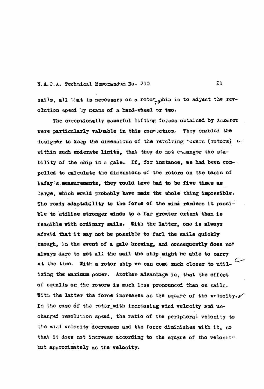
W t appro-xinratelp a3 tbe velocity.

be able t o revolve on the tearing at tte extrene right in Fig. l9,
an& could be prevented f r o m revclving caly by mazs of a 1Lmer
adjoiniq the balance.
Figs- 2C and 21.
the rotors on the shtp. For this pUi.066, a. &el of the skip
Scme of the results obtbimd are &own in
Other experiments hi t o dr, witb the actim of

getic cooneration - of e15ginserr Croseck, wbum . a e Flettner G o m y
sent to &ttingen.
the Oermaxwt Ship Tarhs at =el, whicC &&ably rc~lved the many
difffdt problem prermted- *.
men: desernes spgcia3 mention; > xm~ely, that a kotatioa of the
towers ( e c h aze 8.8 m in & M e r and 15 m
T& work t- 2l&ed w a ~ %en executed at
*-
One especisly remarkable achieve
m ~ v e at
the rate ei 220 R.P.X.) produces practically no noise nor vibra-
' i m p rrork. How that re are enjaping tbe harvest, let 3 s mt for-
get the seedtine, m r neglect tc provide the means for facilitat- ing t o tiie ut;aor;t the hemficent work of OUT scientific institu-
tions.
Translated in Office of I2Wm.l. Attache, ger'lin. Revised by Do- E. Ylaer, TJ. A. C o A 0

Fig, 3 ?liagr,.cm of circcicticn

a cyliridar
Fig. 6 “he flows f n Figs. 4 & li vsc- t a r i z l y combinad. The r 2 6 ~ l t m t flow produc.?s i! lift.

P i g , 7 Przssurz end skctr ing forcze in a viscous fl-xid.
Figs. 7 E 8

N . A . C . A . Techniosl Yewlracdcs IC. 310 Figs.3,10,ii dt 13
--- Fig. 12 Strean. l i nes ~ x i Ear- gkal layer in thz cas2 of a rotatirig cylinder, f r c s a phot@ by Prasdtl .

2LA.C ,A, lcchnicel Li3morpJLd’um No. 310
F i g . 13 F l o ~ through t r o conatricTicus
Pigs. 14 & 15 Experiaentai arra-agxent f o r dstermiaing the rm.gr..itu& cf the 2agm8 sffect .

W ’ r x q s . 16,17,18 &. 13
+ -e{- Fig. 16 - - - c- Effect cf a high negative pressure CL the air next t c :he cylindcr.
-Fig. 17 InZlc~ cf iieighboring air, in spite o f fixcd disks-
1
Fig. -
18 Inflow of neighboring air mevented by rota-
cylinder. b i q - d i s k s on ends Gf
n- ~ l g , 13 Rctating cyiinder with buil t - ix a c t o r for the more accurate w i n d tunnel t e s t s .

I I .' 1 2 3 4
u/v Fig. 20 Expcr,,. l-csults wish a rotating c y l i n d z r ,
d ime ta r 70 mm, length 330 a. W i n d velooi ty v = II rn/aZc.
9
8
7
6
c
3
c r
3
2
1
a
C crJ
Fig. 21 L i f t coe f f i c i en t s Gf EL rotating cylinder o f 7C mm dizneter axxi 330 Ern length, with- c u t erd disks and with end disks of 120 nnd 40 mrn d.inmoter,