microcontrollers: introduction -...
TRANSCRIPT

1
Microcontrollers: Introduction
Dott.Credits: Domenico BalsamoMichele Magno
Luca Benini

2
Embedded Systems
Embedded computing system: any device that includes a programmable computer but is not itself a general‐purpose computer.
One or more microcontrollers (MCU) hidden in a variety of devices and objects:
The MCU has to control and enhance the functionalities of the device
The MCU is a secondary characteristic and must have a small impact on resource consumption and costs.

3
Digital Electronic Integrated circuit
4
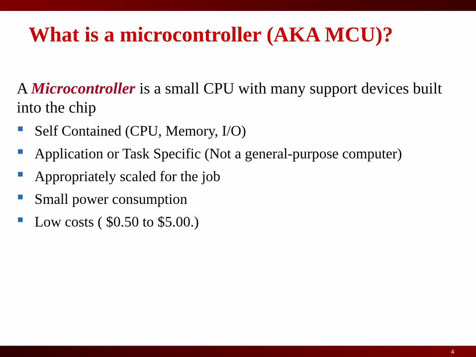
What is a microcontroller (AKA MCU)?
A Microcontroller is a small CPU with many support devices built into the chip
Self Contained (CPU, Memory, I/O)
Application or Task Specific (Not a general-purpose computer)
Appropriately scaled for the job
Small power consumption
Low costs ( $0.50 to $5.00.)

5
MCU-Based System Architecture
Flexible sensor interface
Ultralow power standby
Very Fast wakeup
Watchdog and Monitoring
Efficient wireless protocol primitives
Data SRAM is critical limiting resource
proc
DataSRAM pgm
EPROM
timersSensor Interface digital sensors
analog sensorsADC
Wireless NetInterface
Wired NetInterface
RFtransceiver
antenna
serial linkUSB,EN,…
Power supply-Standby & Wakeup
Flash Storage
pgm images
data logs
WD
6
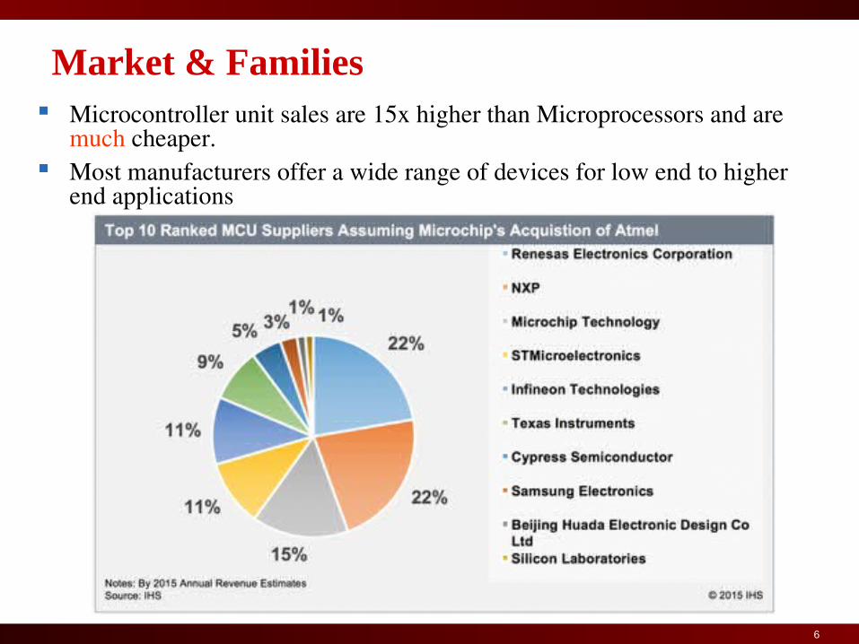
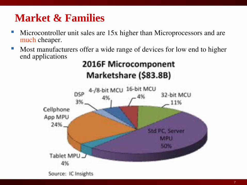
Market & Families Microcontroller unit sales are 15x higher than Microprocessors and are
much cheaper. Most manufacturers offer a wide range of devices for low end to higher
end applications
7
Market & Families Microcontroller unit sales are 15x higher than Microprocessors and are
much cheaper. Most manufacturers offer a wide range of devices for low end to higher
end applications
8
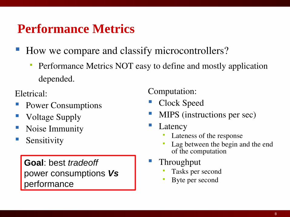
How we compare and classify microcontrollers? Performance Metrics NOT easy to define and mostly application
depended.
Performance Metrics
Computation: Clock Speed MIPS (instructions per sec) Latency
Lateness of the response Lag between the begin and the end
of the computation Throughput
Tasks per second Byte per second
Goal: best tradeoff power consumptions Vs performance
Eletrical: Power Consumptions Voltage Supply Noise Immunity Sensitivity
9
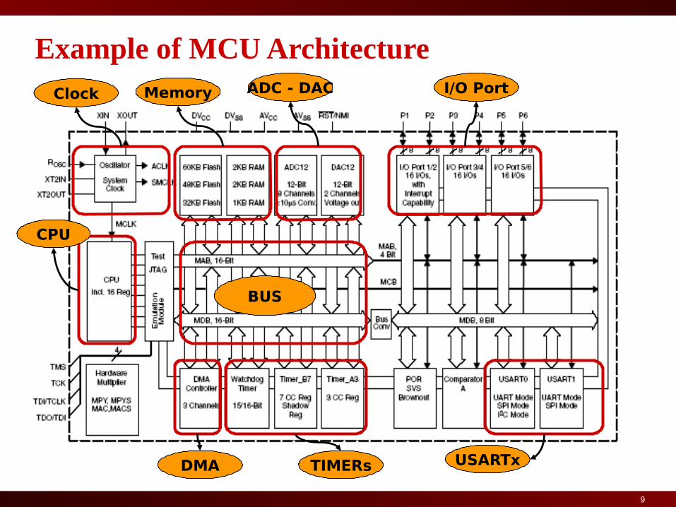
Example of MCU Architecture I/O PortADC - DAC
USARTxTIMERsDMA
MemoryClock
BUS
CPU

10
The MCU CORE An instruction processor
Characteristic Instruction set
- CISC Complex Instruction Set Computing (Intel x86 family; Motorola 680x0 Family)- RISC Reduced Instruction Set computer (AIM Power PC, ARM family, ATMEL AVR Family)
Architecture (respect integer operand maximum dimension)- 8 bit (Intel 8051, Motorola 6800, ATMEL AVR ) - 16 bit (Intel 8088, Motorola 68000, TI MSP430)- 32 bit (ARM v7, x86 family, Motorola 680x0 Family, Power PC)- 64 bit (ARM v8, x86-64 family, Power PC)

11
Datapath & Control
Datapath: Storage, FU, interconnect sufficient to perform the desired functions Inputs are Control Points Outputs are signals (such as overflow, negative, etc)
Controller: State machine to orchestrate operation on the data path Based on desired function and signals 11
Datapath Controller
Control Points
signals
12
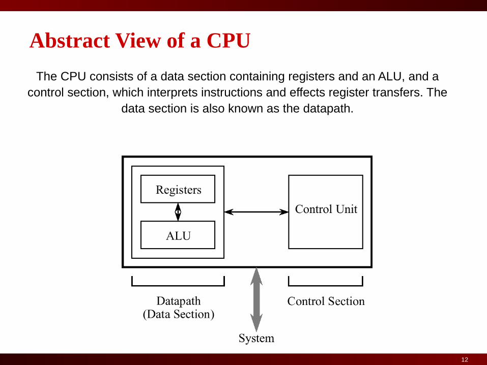
The CPU consists of a data section containing registers and an ALU, and a control section, which interprets instructions and effects register transfers. The
data section is also known as the datapath.
Abstract View of a CPU

13
The datapath usually consists of a collection of registers known as the register file and the arithmetic and logic unit (ALU).
An Example Datapath
14
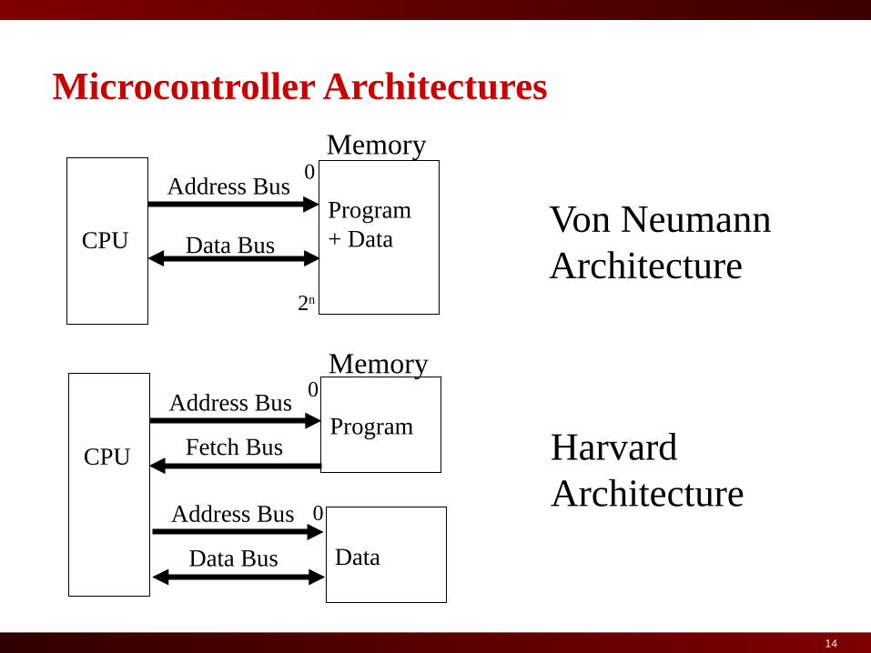
Microcontroller Architectures
CPUProgram + Data
Address Bus
Data Bus
Memory
Von NeumannArchitecture
CPUProgram
Address Bus
Data Bus
HarvardArchitecture
Memory
Data
Address Bus
Fetch Bus
0
0
0
2n

15
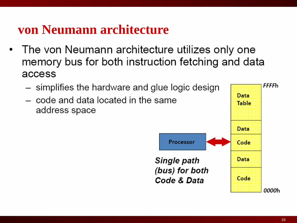
von Neumann architecture
Memory holds data, instructions.
Central processing unit (CPU) fetches instructions from memory. Separate CPU and memory distinguishes programmable computer.
CPU registers help out: program counter (PC), instruction register (IR), general-purpose registers, etc.
16
von Neumann architecture
17
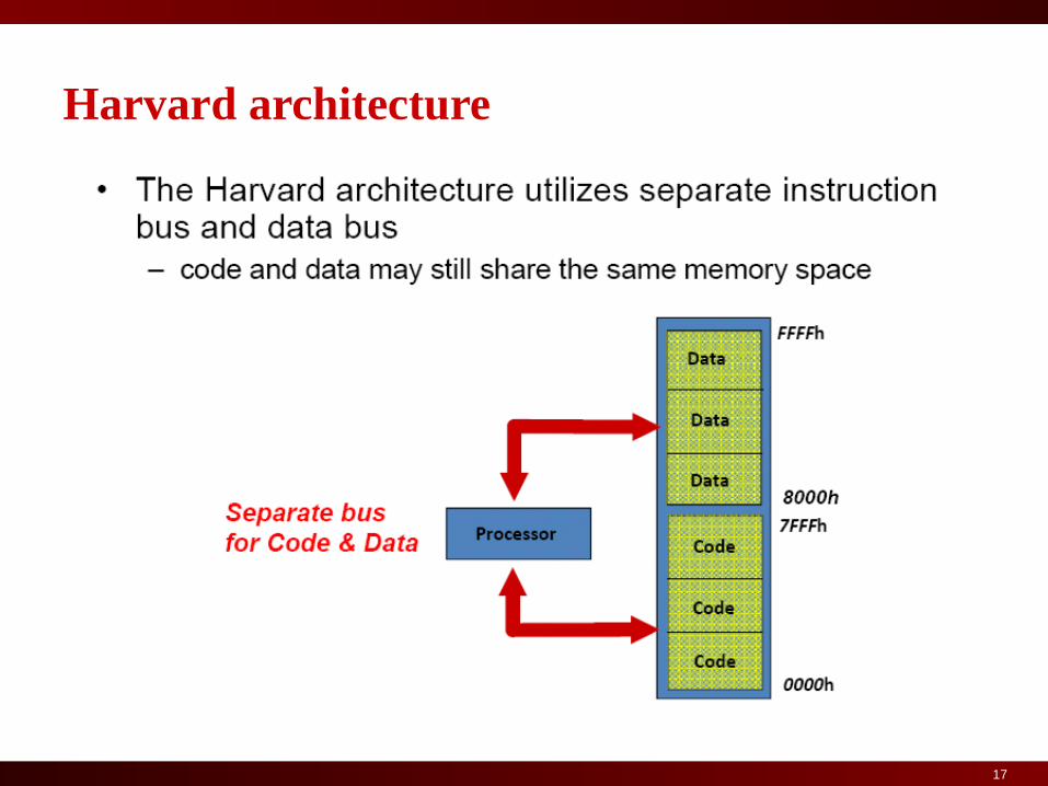
Harvard architecture
18
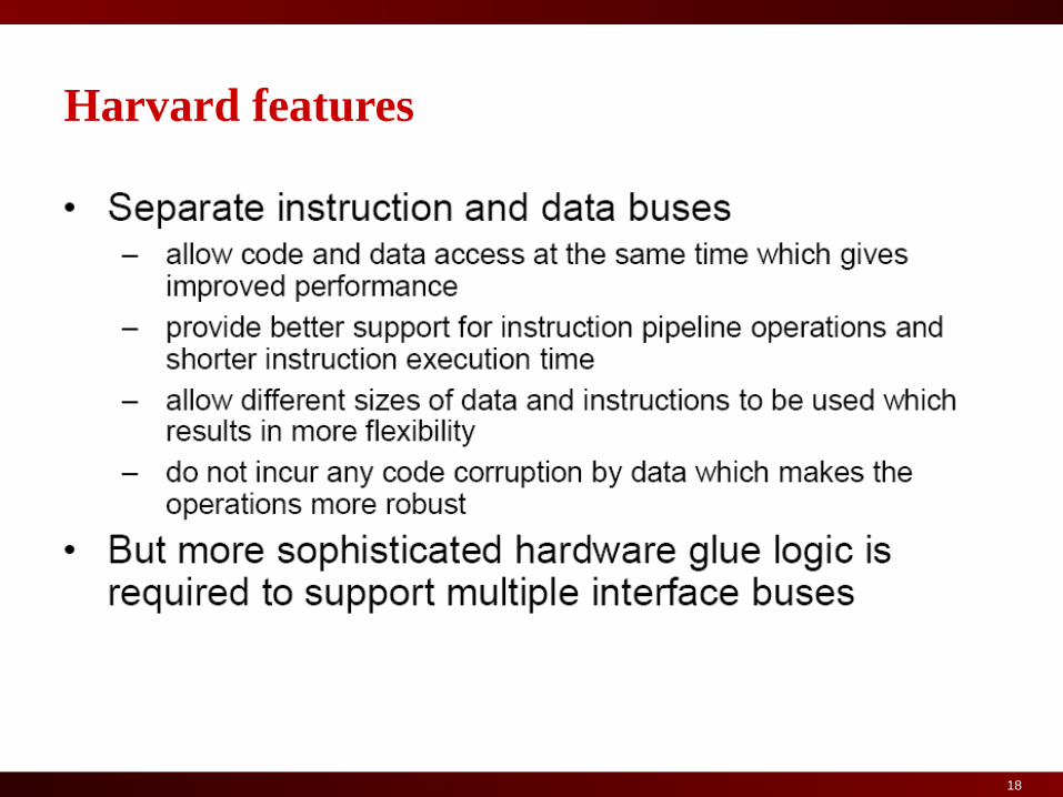
Harvard features

19
von Neumann vs. Harvard Harvard can’t use self-modifying code.
Harvard allows two simultaneous memory fetches.
Most DSPs use Harvard architecture for streaming data:
greater memory bandwidth;
more predictable bandwidth.
20
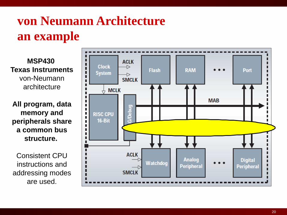
von Neumann Architecture an example
MSP430 Texas Instruments
von-Neumann architecture
All program, data memory and
peripherals share a common bus
structure.
Consistent CPU instructions and
addressing modes are used.

21
Harward Architecture Example
Cortex M3: The mainstream ARM
processor for microcontroller applications.
High performance and energy efficiency.
21

22
Architecture Variations
23
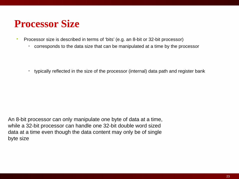
Processor Size Processor size is described in terms of ‘bits’ (e.g. an 8-bit or 32-bit processor)
- corresponds to the data size that can be manipulated at a time by the processor
- typically reflected in the size of the processor (internal) data path and register bank
An 8-bit processor can only manipulate one byte of data at a time, while a 32-bit processor can handle one 32-bit double word sized data at a time even though the data content may only be of single byte size

Universität Dortmund
• Multiple stages are involved in executing an instruction.– Example: 1) Fetching the instruction code
2) Decoding the instruction code
3) Executing the instruction code
• Hence multiple processor clock cycles are needed to execute one single instruction.
Fetch Instruction
Decode Instruction
Execute Instruction
time
Fetch Instruction
Decode Instruction
Execute Instruction
1st
2nd
Instruction Execution

Universität Dortmund
• The pipeline allows concurrent execution of multiple different instructions– execution of different stages of multiple instructions at the same time
• During a normal operation– while one instruction is being executed– the next instruction is being decoded– and a third instruction is being fetched from memory– allows effective throughput to increase to one instruction per clock cycle
Instruction Pipeline
Universität Dortmund
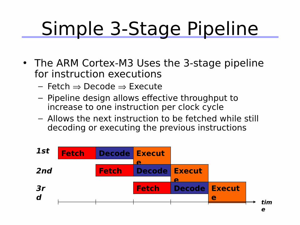
Simple 3-Stage Pipeline
• The ARM Cortex-M3 Uses the 3-stage pipeline for instruction executions– Fetch Decode Execute– Pipeline design allows effective throughput to
increase to one instruction per clock cycle– Allows the next instruction to be fetched while still
decoding or executing the previous instructions
Fetch Decode Execute
Fetch Decode Execute
Fetch Decode Execute
1st
2nd
3rd
time

27
Why Ultra-low Power Is so Important for MCUs?
Longer battery life
Smaller products
Simpler power supplies
Less EMI simplifies PCB
Permanent battery
Reduced liability

28
Power as a Design Constraint
Why worry about power? Battery life in portable and mobile platforms Power consumption in desktops, server farms
- Cooling costs, packaging costs, reliability, timing- Power density: 30 W/cm2 in Alpha 21364 (3x of typical hot plate)
Where does power go in CMOS?
Dynamic power consumption
Power due to short-circuit current during transition
Power due to leakage current
leakshort2 VIfAVIfACVP

29
Dynamic Power Consumption
A Activity of gates How often on average do wires switch?
f – clock frequencyTrend: increasing ...
V – Supply voltage Trend: has been dropping with each successive fab
C – Total capacitance seen by the gate’s outputsFunction of wire lengths,transistor sizes, ...
Reducing Dynamic Power1) Reducing V has quadratic effect; Limits?2) Lower C shrink structures, shorten wires3) Reduce switching activity Turn off unused parts or
use design techniques to minimize number of transitions
fACV2
30
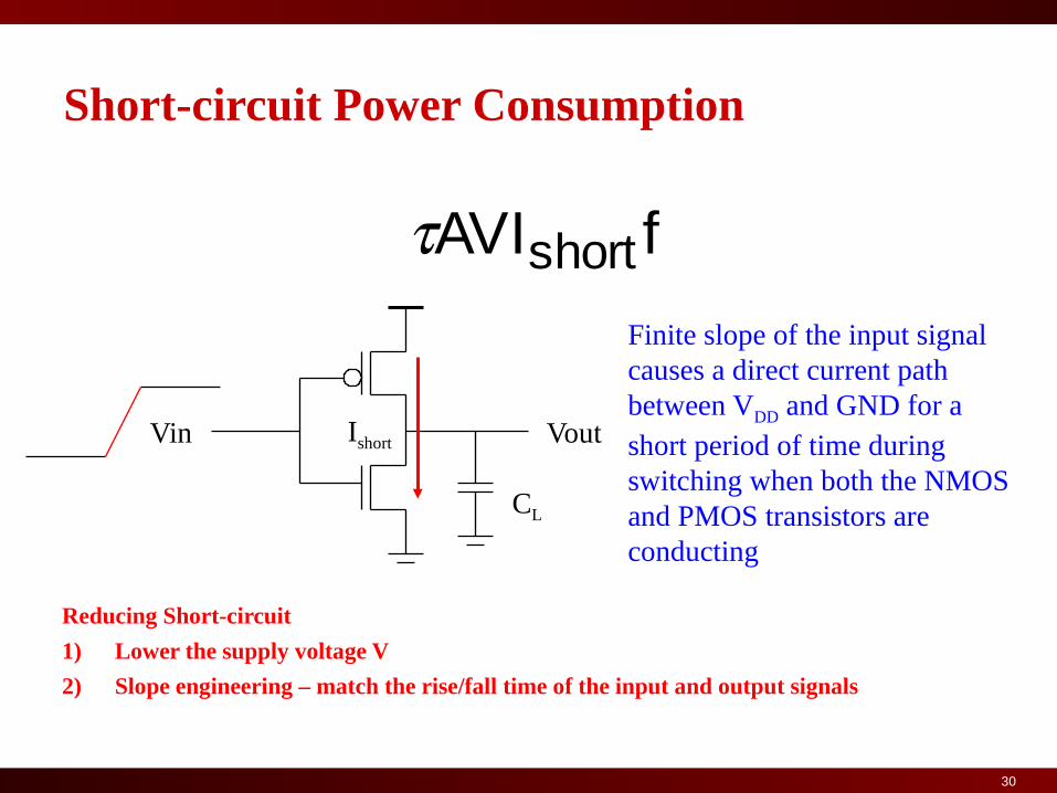
Short-circuit Power Consumption
Finite slope of the input signal causes a direct current path between VDD and GND for a short period of time during switching when both the NMOS and PMOS transistors are conducting
Vin Vout
CL
Ishort
Reducing Short-circuit
1) Lower the supply voltage V
2) Slope engineering – match the rise/fall time of the input and output signals
fAVIshort

31
Leakage Power
Sub-threshold current grows exponentially with increases in temperature and decreases in Vt
Sub-threshold current
leakVI

32
How can we reduce power consumption?
Dynamic power consumption Reduce the rate of charge/discharge of highly loaded nodes Reduce spurious switching (glitches) Reduce switching in idle states (clock gating) Decrease frequency Decrease voltage (and frequency)
Static power Consumption Smaller area (!) Reduce device leakage through power gating Reduce device leakage through body biasing Use higher-threshold transistors when possible
Power performance tradeoffs!

33
Typical Ultra-Low Power MCU Architecture
System Clock
Generator
ACLK
SMCLK
MCLK
CPU
Key Feature
• MCLK Main clock provided to the CPU
• SMCLK SubMain clock provided to the peripherals
• ACLK Auxiliary clock at low frequency provided to
the peripherals
• Peripherals can work at High and Low frequency
• Each Clock can be disabled (Clock Gating, reducing
dynamic power) by setting the status register SR.
• The CPU can be disabled (reducing Leakage power)
by setting the SR.
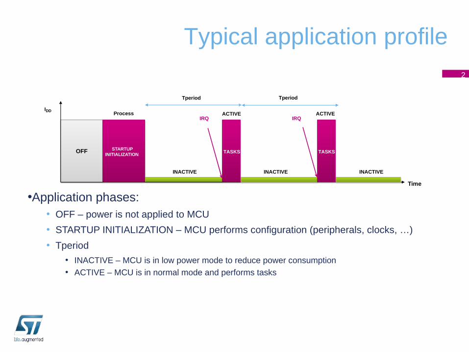
Typical application profile
Time
•Application phases:• OFF – power is not applied to MCU
• STARTUP INITIALIZATION – MCU performs configuration (peripherals, clocks, …)
• Tperiod
• INACTIVE – MCU is in low power mode to reduce power consumption• ACTIVE – MCU is in normal mode and performs tasks
2
OFF STARTUP INITIALIZATION
IRQ
IDD
IRQ
TASKS
Process ACTIVE
INACTIVE
Tperiod Tperiod
TASKS
ACTIVE
INACTIVE INACTIVE
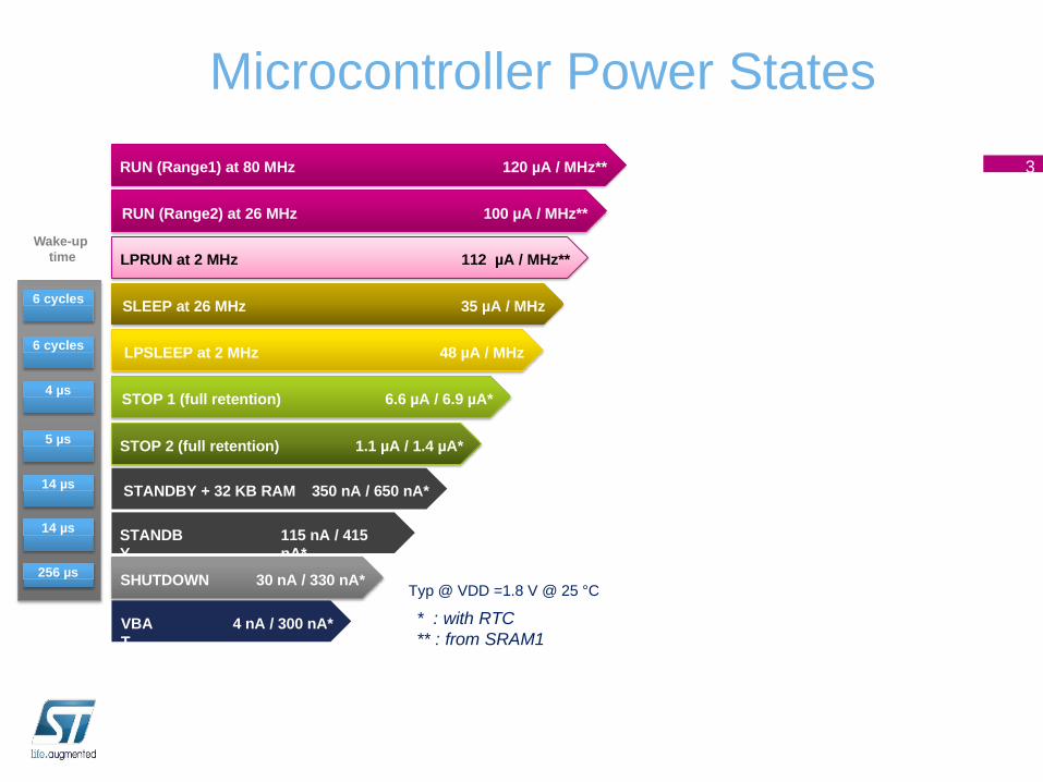
Microcontroller Power States
3RUN (Range1) at 80 MHz 120 µA / MHz**
STANDBY
115 nA / 415 nA*
VBAT
4 nA / 300 nA*
SHUTDOWN 30 nA / 330 nA*
STANDBY + 32 KB RAM 350 nA / 650 nA*
256 µs
14 µs
14 µs
5 µs
6 cycles
Wake-up time
4 µs
STOP 2 (full retention) 1.1 µA / 1.4 µA*
LPSLEEP at 2 MHz 48 µA / MHz
RUN (Range2) at 26 MHz 100 µA / MHz**
STOP 1 (full retention) 6.6 µA / 6.9 µA*
Typ @ VDD =1.8 V @ 25 °C
* : with RTC** : from SRAM1
6 cycles SLEEP at 26 MHz 35 µA / MHz
LPRUN at 2 MHz 112 µA / MHz**

Universität Dortmund
ARM Processors Families
36

Universität Dortmund
• Key attributes: Implementation size, performance, and very low power.
• Architectures types:– ARMv4T architecture introduced the 16-bit Thumb® instruction
set alongside the 32-bit ARM instruction set.– ARMv5TEJ architecture introduced arithmetic support for digital
signal processing (DSP) algorithms.– ARMv6 architecture introduced an array of new features including
the Single Instruction Multiple Data (SIMD) operations.– ARMv7 architecture implementsThumb-2 technology.
• Cortex-A implements a virtual memory system architecture based on an MMU, an optional NEON processing unit for multimedia applications and advanced hardware Floating Point.
• Cortex-R – implements a protected memory system architecture based on an MPU (memory protection unit).
• Cortex-M – Microcontroller profile designed for fast interrupt processing.
– ARMv8 implementing 64bit instruction set
ARM Processors Architectures (2)
37Alberto Macii - Politecnico di Torino
Universität Dortmund
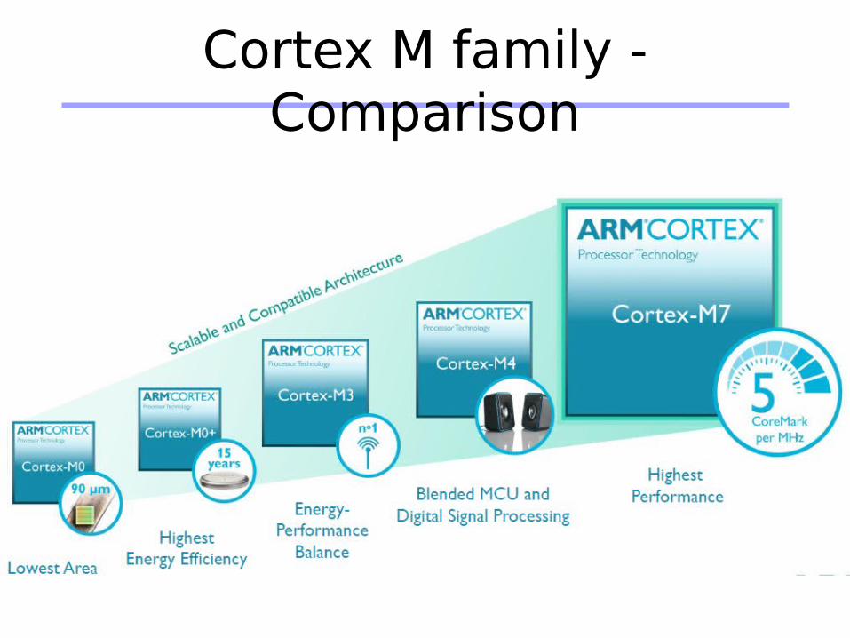
Cortex M family - Comparison

Universität Dortmund
Embedded ARM Cortex Processors
• Cortex M0:– Ultra low gate count
(less that 12 K gates).
– Ultra low-power (3 µW/MHz ).
– 32-bit processor.
39
Universität Dortmund
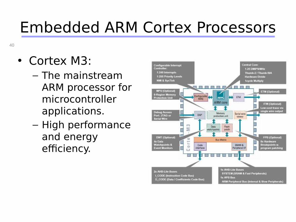
Embedded ARM Cortex Processors
• Cortex M3:– The mainstream
ARM processor for microcontroller applications.
– High performance and energy efficiency.
40

Universität Dortmund
Cortex M3 Central Core
• Harvard architecture:– Separate Instruction & Data buses
enable parallel fetch & store.
• Advanced 3-Stage Pipeline:– Includes Branch Forwarding &
Speculation
• Additional Write-Back via Bus Matrix.
41
Alberto Macii - Politecnico di Torino
Universität Dortmund
Embedded ARM Cortex Processors (4)
42
Cortex M4Embedded processor for DSP with FPU

Universität Dortmund
Cortex M7
2x Perf of M4

Universität Dortmund
ARMv8 64bit
• Premium smartphones
• Enterprise servers
• Home server• Wireless
Infrastructure• Digital TV

Universität Dortmund
Cortex A57 Block Diagram
Universität Dortmund
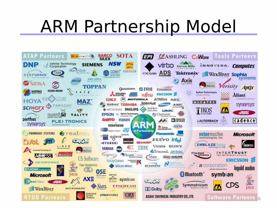
ARM Partnership Model
46Alberto Macii - Politecnico di Torino
High-performance Cortex™-M4 MCU
STM32 F4 series
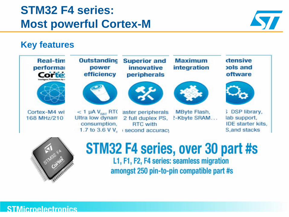
STM32 F4 series: Most powerful Cortex-M
Key features
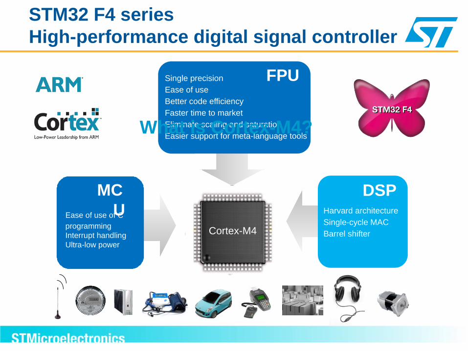
STM32 F4 seriesHigh-performance digital signal controller
Single precisionEase of use
Better code efficiency
Faster time to market
Eliminate scaling and saturationEasier support for meta-language tools
FPU
Harvard architecture
Single-cycle MACBarrel shifter
DSPEase of use of C programmingInterrupt handlingUltra-low power
MCU
Cortex-M4
What is Cortex-M4?
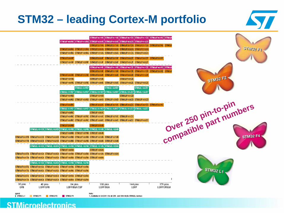
STM32 – leading Cortex-M portfolio
Over 250 pin-to-pin
compatible part numbers
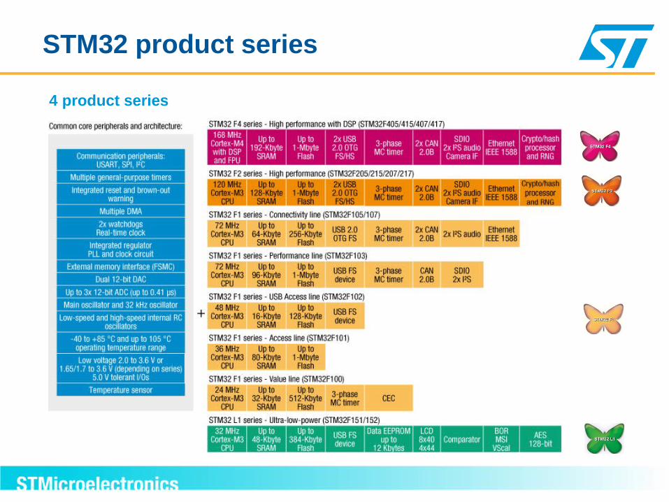
STM32 product series
4 product series

STM32 F4 portfolio
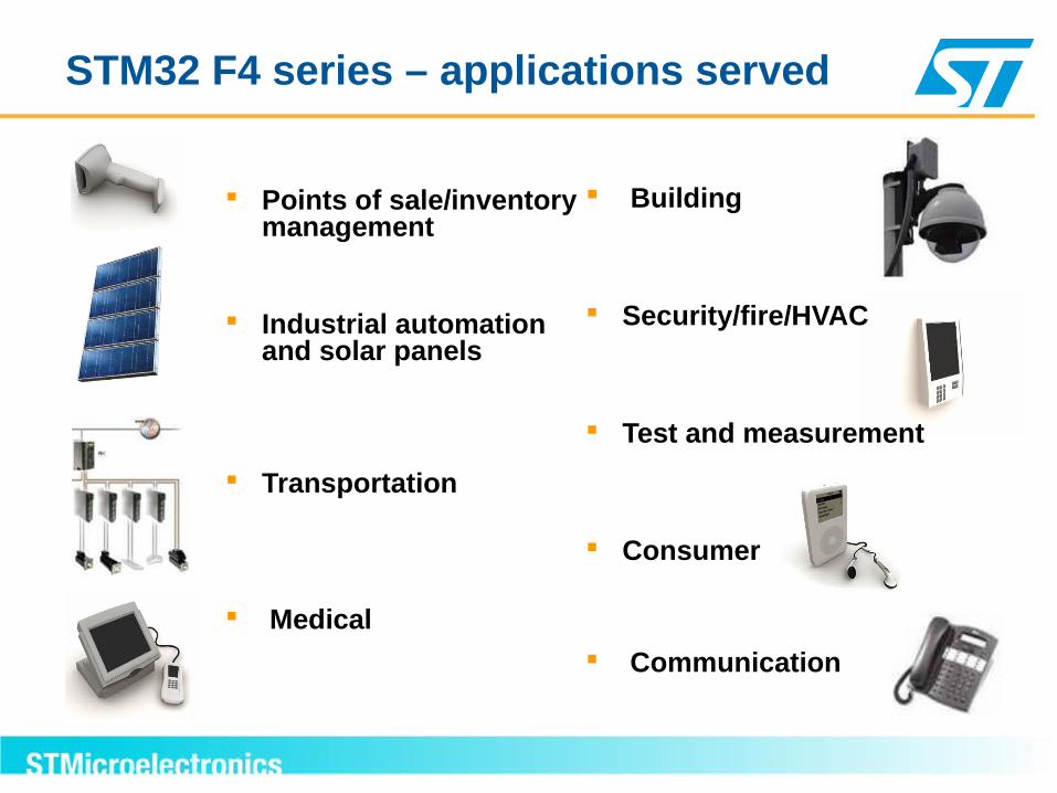
STM32 F4 series – applications served
Points of sale/inventory management
Industrial automation and solar panels
Transportation
Medical
Building
Security/fire/HVAC
Test and measurement
Consumer
Communication
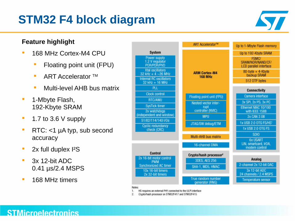
STM32 F4 block diagram
Feature highlight
168 MHz Cortex-M4 CPU
Floating point unit (FPU)
ART Accelerator TM
Multi-level AHB bus matrix
1-Mbyte Flash, 192-Kbyte SRAM
1.7 to 3.6 V supply
RTC: <1 µA typ, sub second accuracy
2x full duplex I²S
3x 12-bit ADC 0.41 µs/2.4 MSPS
168 MHz timers

51/82/114/140 I/Os
USB 2.0 OTGFS/HS
Encryption**
Camera Interface
3x 12-bit ADC24 channels / 2Msps
3x I2C
Up to 16 Ext. ITs
Temp Sensor
2x6x 16-bit PWMSynchronized AC Timer
2x Watchdog(independent& window)
5x 16-bit Timer
XTAL oscillators32KHz + 8~25MHz
Power Supply Reg 1.2V
POR/PDR/PVD
2x DAC + 2 Timers
2 x USART/LIN
1 x SPI
1 x Systic Timer
PLLClock Control
RTC / AWU
4KB backup RAM
Ethernet MAC 10/100, IEEE1588
USB 2.0 OTG FS
4x USART/LIN
1x SDIO
Int. RC oscillators32KHz + 16MHz
3 x 16bit Timer
2x 32-bit Timer
2x CAN 2.0B
2 x SPI / I2S
HS requires an external PHY connected to ULPI interface,** Encryption is only available on STM32F415 and STM32F417 4
STM32F4xx Block Diagram vith details Cortex-M4 w/ FPU, MPU and ETM Memory
Up to 1MB Flash memory 192KB RAM (including 64KB
CCM data RAM FSMC up to 60MHz
New application specific peripherals USB OTG HS w/ ULPI interface Camera interface HW Encryption**: DES, 3DES,
AES256-bit, SHA-1 hash, RNG. Enhanced peripherals
USB OTG Full speed ADC: 0.416µs conversion/2.4Msps,
up to 7.2Msps in interleaved triplemode
ADC/DAC working down to 1.8V Dedicated PLL for I S precision Ethernet w/ HW IEEE1588 v2.0 32-bit RTC with calendar 4KB backup SRAM in VBAT
domain 2 x 32bit and 8 x 16bit Timers high speed USART up to 10.5Mb/s high speed SPI up to 37.5Mb/s
2
RDP (JTAG fuse) More I/Os in UFBGA 176
package
AR
M ®
32-
bit
mu
lti-A
HB
bu
s m
atri
x A
rbite
r (m
ax 1
68M
Hz) F
lash
I/F
CORTEX-M4 CPU + FPU + MPU168 MHz
128KB SRAM
DMA16 Channels
Bridge
Bridge APB1 (max 42MHz)
JTAG/SW Debug
ETM
Nested vect IT Ctrl
512kB- 1MBFlash Memory
External Memory Interface
AHB1
(max 168MHz)
AHB2 (max 168MHz)
AP
B2
(m
ax 8
4MH
z)
64KB CCM data RAM
D-bus
I-bus
S-bus

Evaluation board for full product feature evaluation Hardware evaluation platform for all interfaces Possible connection to all I/Os and all
peripherals Discovery kit for cost-effective evaluation and
prototyping
Large choice of development IDE solutions from the STM32 and ARM ecosystem
Extensive tools and SW
STM32F4DISCOVERY $14.90
STM3240G-EVAL
$349

57
How to Read Datasheets
Manufacturers of electronic components provide datasheets containing the specifications detailing the part/device characteristics;
Datasheets give the electrical characteristics of the device and the pinout functions, but without detailing the internal operation;
More complex devices are provided with documents that aid the development of applications, such as: Application notes; User's guides; Designer's guides; Package drawings, etc…

58
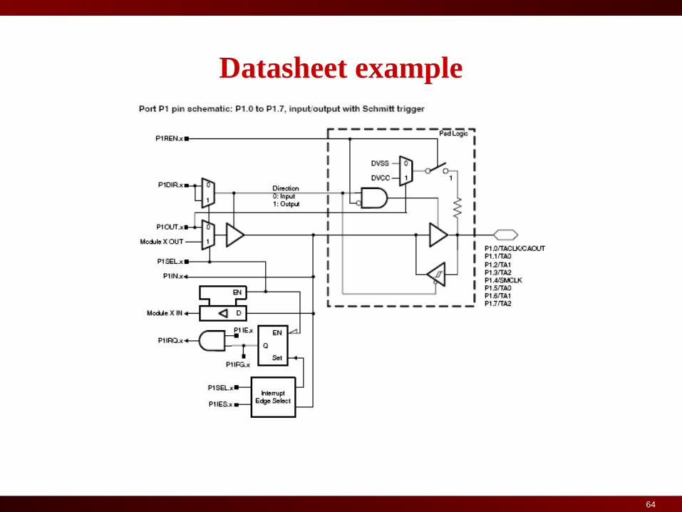
Datasheet example

59
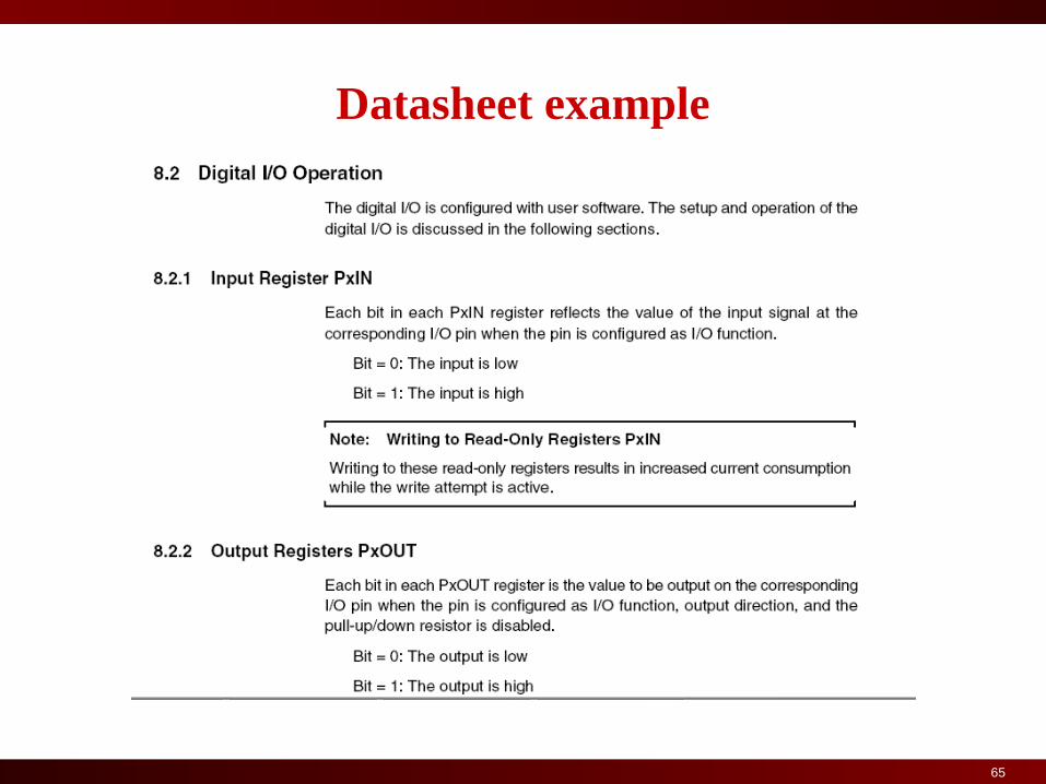
Datasheet example

60
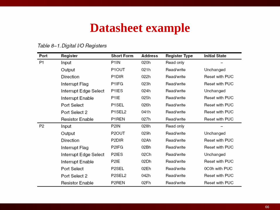
Datasheet example
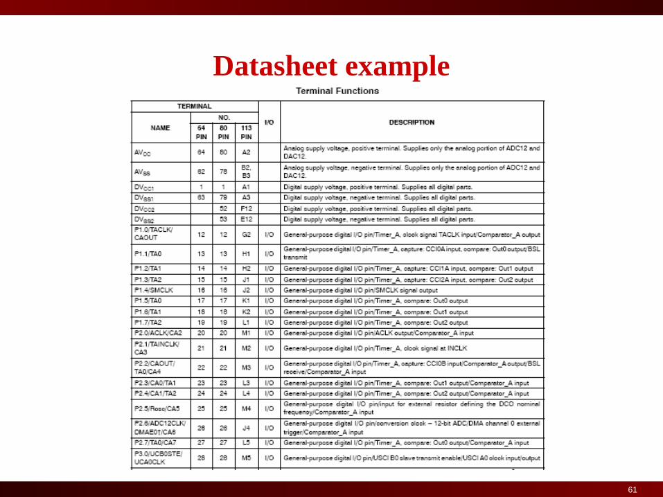
61
Datasheet example

62
Datasheet example

63
Datasheet example
64
Datasheet example
65
Datasheet example
66
Datasheet example