microcontroller systems for a uav - urad.online.fr · microcontroller systems ... this report...
TRANSCRIPT
1
Monday, 09 December 2002
Bachelor of Science Degree Thesis
Supervisor : Prof. Thomas LindbladOral presentation: 4th December 2002
Microcontroller Systemsfor a UAV
Auto Piloting and Camera Trigger System
Alexandros Skafidas
TRITA-FYS 2002:51ISSN 0280-316 XISRN KTH/FYS/--02:51-SE

2
A. Abstract ..................................................................................................................3B. Acknowledgements ................................................................................................3C. Objective ................................................................................................................31. Introduction............................................................................................................42. What is a Microcontroller ......................................................................................4
2.1. What is a UAV? .............................................................................................52.2. Software development for microcontrollers...................................................52.3. Servos.............................................................................................................72.4. GPS Unit & NMEA Protocol.........................................................................72.5. SPI Protocol....................................................................................................8
3. Camera Trigger Unit ..............................................................................................93.1. Details of Camera Trigger Unit....................................................................10
3.1.1. Camera .................................................................................................103.1.2. External EEPROM IC ..........................................................................11
3.2. Camera Trigger Program Flow....................................................................113.2.1. ICP Interrupt.........................................................................................113.2.2. Timer Interrupt .....................................................................................123.2.3. UART Interrupt....................................................................................123.2.4. Saving picture information to the EEPROM.......................................133.2.5. Uploading picture information to a PC ................................................14
4. Waypoint Direction Finder Unit ..........................................................................164.1. Waypoint Direction Finder Program Flow...................................................174.2. Future improvements....................................................................................17
5. Altimeter / Altitude Hold Unit .............................................................................185.1. Pressure Sensor ............................................................................................185.2. Analogue to Digital Converter .....................................................................195.3. Altimeter Program Flow...............................................................................205.4. Altitude from Pressure .................................................................................205.5. Accuracy.......................................................................................................215.6. Signal Conditioning......................................................................................215.7. Future Improvements ...................................................................................22
D. Conclusion............................................................................................................23E. Abbreviations .......................................................................................................24F. Sources.................................................................................................................25G. Internet Links .......................................................................................................25I. Appendix (Program Flow Charts)........................................................................26
a. Camera Trigger Unit ........................................................................................26b. Waypoint Direction Finder Unit ......................................................................26c. Altimeter / Altitude Hold Unit .........................................................................26
J. Appendix (C-Code)..............................................................................................35a. Altitude Hold ....................................................................................................35b. Waypoint Direction Finder Unit ......................................................................39c. Camera Trigger Unit ........................................................................................43d. Common Subroutines (LCD, Delay)................................................................49e. NMEA field extracting code ............................................................................51
K. Appendix (Schematics)........................................................................................53L. Appendix (PCB)...................................................................................................56

3
A. AbstractThis report describes the development of three electronic devices, primarily designedfor use aboard an unmanned aerial vehicle (UAV). Descriptive names were given tothese devices (also called units) to emphasize their function.These devices are:ð“Camera Trigger Unit”ð “Waypoint Direction Finder Unit”ð “Altimeter / Altitude Hold Unit”
The first device connects to a camera and a commercial Global PositioningSystem (GPS) receiver. A photograph can be snapped manually from the ground witha receiver / transmitter, or automatically when the GPS overflies a preprogrammedlocation.
Secondly the waypoint direction finder unit is used to guide/steer the aircrafttowards a preprogrammed waypoint or a route of waypoints. This is achieved partlywith help of the onboard GPS
Finally the altimeter unit is used for measuring altitude. Indications are givenabout how it can be further developed into an “altitude hold unit”.
Each device is built with various electronic components, but they all have onething in common. Each device has a special kind of microprocessor, called amicrocontroller which is the “heart” of the device. Most of the work for this projectinvolved the development of software for these microcontrollers. As a result thisreport gives a detailed description of the program flow. A description of the variousphysical parts that make up these units is also given. The production phase wascompleted with the design and manufacturing of printed circuit boards, thus makingthese units truly stand alone electronic devices.
All the units met the requirements and some units even offered additionalfeatures not included in the original plans. The project proved to be very educative, asit involved all sorts of debugging, from hardware to software. Theory was always putto test in the constant interaction between theory and practice. In addition it offered agood understanding of the development stages of an electronic product from a roughsketch to a working device.
B. AcknowledgementsI would like to thank the following people for their financial, as well as theireducational support.• Thomas Lindblad, KTH (Royal Institute of Technology)• Nils Hollman, NDH Marketing• Sten Hollman, NDH Marketing• Johan Puscov
C. ObjectiveThe objective is to produce a number of electronic microcontroller based devices forintegration into the autopiloting and payload system of an unmanned aerial vehicle.The autopiloting unit should be responsible for steering the aircraft towards apredefined waypoint, or along a route of waypoints. It should also attempt to stabilizethe aircraft to a certain altitude. Another device should be able to trigger the UAV’spayload, which consists of a digital camera.
4
1. IntroductionThe given assignment was to construct a number of electronic devices to be usedaboard a UAV. These devices are as previously mentioned: a “camera trigger unit”, a“waypoint direction finder unit” and an “altimeter/altitude hold unit”.
The easiest way to meet the requirements specified by the project’s objectivewith a limited amount of hardware was by the use of a microcontroller. But thedecreased complexity in hardware offered by the microcontroller results in increasedcomplexity in the software within it. It was natural to expect that this project wouldrequire a considerable amount of software, but also hardware skills. Before going intodetails about these three units, a description of all the components used to build themwill be given.
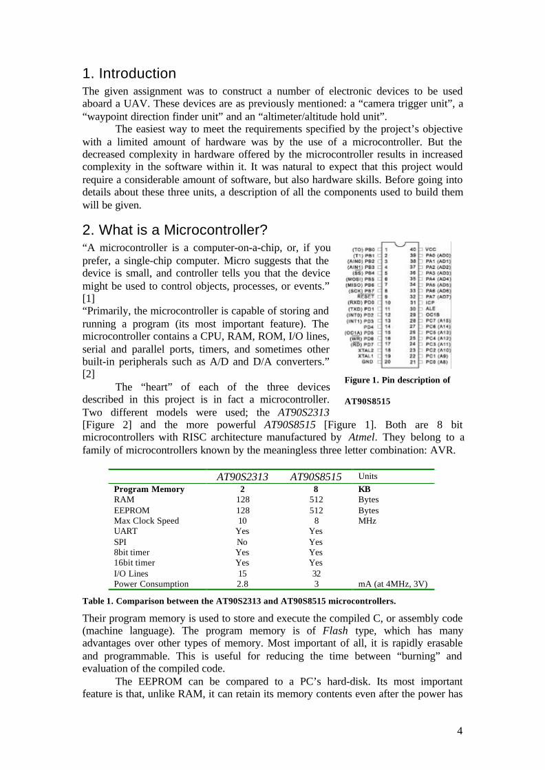
2. What is a Microcontroller?“A microcontroller is a computer-on-a-chip, or, if youprefer, a single-chip computer. Micro suggests that thedevice is small, and controller tells you that the devicemight be used to control objects, processes, or events.”[1]“Primarily, the microcontroller is capable of storing andrunning a program (its most important feature). Themicrocontroller contains a CPU, RAM, ROM, I/O lines,serial and parallel ports, timers, and sometimes otherbuilt-in peripherals such as A/D and D/A converters.”[2]
The “heart” of each of the three devicesdescribed in this project is in fact a microcontroller.Two different models were used; the AT90S2313[Figure 2] and the more powerful AT90S8515 [Figure 1]. Both are 8 bitmicrocontrollers with RISC architecture manufactured by Atmel. They belong to afamily of microcontrollers known by the meaningless three letter combination: AVR.
AT90S2313 AT90S8515 UnitsProgram Memory 2 8 KBRAM 128 512 BytesEEPROM 128 512 BytesMax Clock Speed 10 8 MHzUART Yes YesSPI No Yes8bit timer Yes Yes16bit timer Yes YesI/O Lines 15 32Power Consumption 2.8 3 mA (at 4MHz, 3V)
Table 1. Comparison between the AT90S2313 and AT90S8515 microcontrollers.
Their program memory is used to store and execute the compiled C, or assembly code(machine language). The program memory is of Flash type, which has manyadvantages over other types of memory. Most important of all, it is rapidly erasableand programmable. This is useful for reducing the time between “burning” andevaluation of the compiled code.
The EEPROM can be compared to a PC’s hard-disk. Its most importantfeature is that, unlike RAM, it can retain its memory contents even after the power has
Figure 1. Pin description of
AT90S8515

5
been turned off. In microcontroller applications it is used for saving initialization orcalibration information. It is important to point out that the EEPROM also has twomain disadvantages. Unlike RAM memory, this kind of memory has a limited lifeexpectancy. The memory gets “worn out” after around 100,000 read/write cycles.Therefore the program should be written so that it makes little use of the EEPROM,and if possible, no use at all. The second disadvantage is that the “write time” can be5ms, but since programs rarely write to the EEPROM, if ever, this does usually notpose a problem.
The clock speed basically decides how fast the codegets executed. Most of the simple assembler instructionscan be executed in a single clock cycle. This means that,at least theoretically, at 8MHz the microcontroller isexecuting 8 MIPS.
The full duplex UART is one of the mostexploited microcontroller features in this project. Polledor interrupt mode can be used to check for incomingcharacters. To reduce the load on the program, theinterrupt mode was chosen. Every incoming characterfires an interrupt which redirects the program flow to a
part of the code responsible for handling the incoming characters. In the UARTinterrupt subroutines the program usually waits for a special sequence of characters,in other words, it filters the incoming stream. Requested characters are temporarilystored in a string in RAM memory.
The I/O ports are of course essential to a microcontroller, for its ability to tocontrol. The AT90S8515 delivers four ports with 8 pins each, a total of 32 I/O pins.Any pin can be configured as an input or an output, and this pin assignment does nothave to remain static but can change dynamically in runtime. Very few peripheraldevices were used in this project, and such a big number of I/O pins was not required.
All signal levels are digital, so the microcontroller can connect only to digitaldevices. The pressure sensor used in the altimeter unit is an analogue device.Therefore for it to interact with the microcontroller, an ADC was used, to convertfrom analogue to digital signal levels.
Two timers/counters an 8bit and a 16bit, are available in both microcontrollersfor counting and timing purposes. The number of bits determines the accuracy of themeasurement. A timer is for example used for measuring the width of a pulse in theCamera Trigger Unit.
2.1. What is a UAV?The acronym UAV stands for Unmanned Aerial Vehicle. A UAV is usually a smallsized aircraft, able to fly autonomously thanks to advanced electronics aboard. It is avehicle which, with no external input, can control itself and perform given tasks. Itcan essentially be seen as a robot that can fly.
There is no one ‘regular’ shape or size for UAVs, They are usually designedspecifically for a task, and that task only. Some of the more common current UAVtasks involve aerial surveillance, aerial surveying and meteorological measurement.
2.2. Software development for microcontrollersProgramming a microcontroller normally involves the following steps:
• Coding / Debugging in a high level language (such as C, or Java) or assembler.
Figure 2. Pin description
for the AT90S2313
6
This is the most time consuming step. A compiler for a high level language helps toreduce production time. To program the microcontrollers the ICCAVR PRO v6 C-compiler from Imagecraft was used. Although inline assembly was possible, theprogramming was done strictly in the C language. The source code has beencommented to facilitate any occasional future improvement and maintenance.• Compiling the code into machine language.The machine language file (.hex) does not make any sense to the layman, (or even toan experienced programmer) when examined with a text editor. But it is the onlything the microcontroller will understand, because it contains the original programcode converted into a hexadecimal format. During this step the programmer will bewarned about eventual errors in the program. An interesting feature in theprofessional version of the ICCAVR program (in which the code was written) was theso called Code-compressor option, which allowed more code to be packed into theprogram memory. When the program seems to be complete and free of errors theprogrammer can move to the next step.• Burning the machine language (hex) file into the microcontroller’s programmemory.
This is achieved with a dedicated programmer, which attaches to a PC’speripheral (such as a COM, or a parallel port). In this project the STK500 programmertransferred the machine language file into the microcontroller’s program memory.Part of this project involved debugging. The AVR Studio v4.0 software besides of
communicating with the programmer, itoffered advanced debugging options.Despite this, debugging was not done withthe traditional debugging software, but witha standard LCD to show variables ofinterest. Communications problems that arosebetween different integrated circuits (SPIcommunication), were resolved with adigital oscilloscope.
The microcontrollers wereprogrammed in approximately two secondswith a high speed programming mode. Theprogram memory which is of Flash type,
has, just like the EEPROM, a limited lifespan. On the AVR microcontroller family itmay be reprogrammed up to a thousand times without any risk of data corruption.• EvaluationIf the microcontroller performs all the required tasks and behaves as expected thesoftware development phase is over. If not, the whole procedure will have to berepeated again.
Most of the work with this project involved the above steps, repeated in acircular fashion, until evaluation of the unit revealed if the requirements werefulfilled.
One of the difficulties of programming microcontrollers is the limited amountof resources the programmer has to deal with. In PCs resources such as RAM andprocessing speed are basically limitless when compared to microcontrollers. Incontrast to a PC, the code on microcontrollers should be as low on resources aspossible.
Figure 3. The "circle" of software
development
7
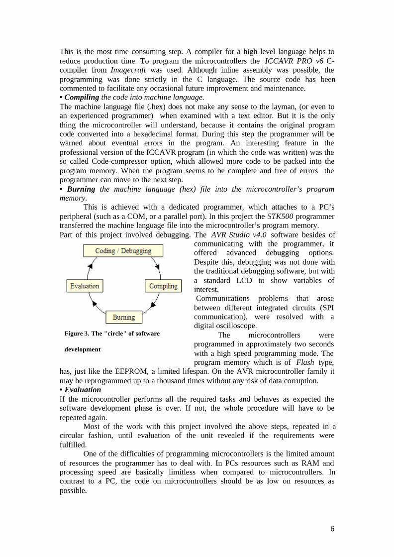
2.3. ServosServos like the one in the picture [Figure 4] are widely used in hobbyrelated constructions. Most of the moving parts of a UAV arecontrolled by these servos, which in turn, are controlled by atransmitter from the ground. The lever position on a servo iscontrolled by a square pulse (Pulse Width Modulation) signal. Theperiod of the pulse regulates the lever position. The period variesbetween one and two milliseconds. A 1ms pulse sets the lever on oneend and a 2ms pulse sets the lever on the opposite end. The
relationship between the lever position and the pulse period is linear; from thisfollows that a 1.5ms pulse is required to place the lever in the central position. If theservo is of the latest generation, known as the “digital” servo, then the signal does nothave to be repeated. But these servos are at present time still not so common.A typical servo requires a constant pulse train to guarantee that its lever will stay inthe same position. Therefore the receivers that connect to these servos will regeneratethe pulse every 20ms.
Figure 5. Timing characteristics of the PWM signal, used to control servos.
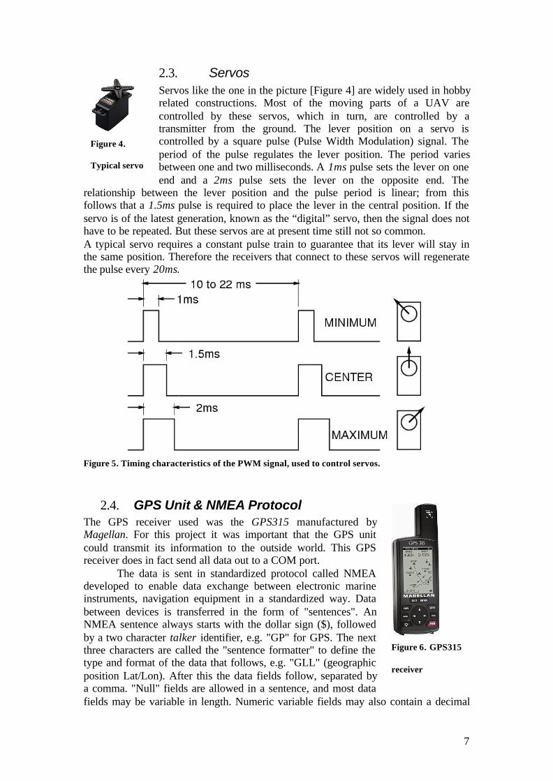
2.4. GPS Unit & NMEA ProtocolThe GPS receiver used was the GPS315 manufactured byMagellan. For this project it was important that the GPS unitcould transmit its information to the outside world. This GPSreceiver does in fact send all data out to a COM port.
The data is sent in standardized protocol called NMEAdeveloped to enable data exchange between electronic marineinstruments, navigation equipment in a standardized way. Databetween devices is transferred in the form of "sentences". AnNMEA sentence always starts with the dollar sign ($), followedby a two character talker identifier, e.g. "GP" for GPS. The nextthree characters are called the "sentence formatter" to define thetype and format of the data that follows, e.g. "GLL" (geographicposition Lat/Lon). After this the data fields follow, separated bya comma. "Null" fields are allowed in a sentence, and most datafields may be variable in length. Numeric variable fields may also contain a decimal
Figure 6. GPS315
receiver
Figure 4.
Typical servo

8
point and leading/trailing zeros. A sentence should be concluded by an "*" followedby a valid checksum.
Example of an NMEA sentence:$GPAPB,A,A,0.0,L,N,A,,357.3,M,SIM002,347.8,M,,,*6A
2.5. SPI ProtocolSPI (Serial Peripheral Interface) is a synchronous serial link used for exchange of databetween integrated circuits on printed circuit boards (PCBs). It is designed for highspeeds and a minimum of external components. An SPI system consists of two datalines and two control lines.
Master Out Slave In (MOSI)This data line supplies the output data from the master which is shifted into theinput(s) of the slave(s).Master In Slave Out (MISO)This data line supplies the output data from a slave to the input of the master. Theremay be no more than one slave which is transmitting data during any particulartransfer. (Guaranteed by the SS line, see below)Slave Select / Chip Select (SS or CS)This control line allows slaves to be turned on and off with hardware control.Normally only one slave can be activated at a given timeSerial Clock (SCLK)This control line is driven by the master and regulates the flow of the data bits. Themaster may transmit data at a variety of baud rates; the SCLK line cycles once foreach bit that is transmitted.
9
3. Camera Trigger Unit
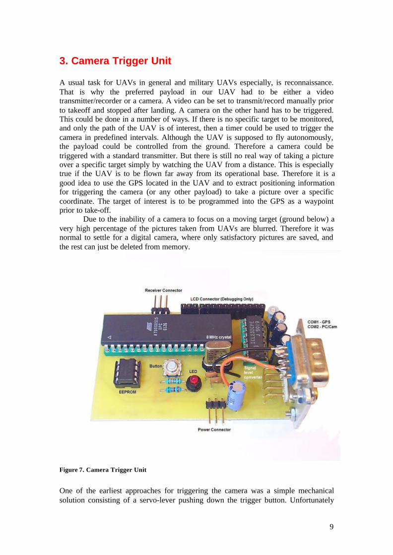
A usual task for UAVs in general and military UAVs especially, is reconnaissance.That is why the preferred payload in our UAV had to be either a videotransmitter/recorder or a camera. A video can be set to transmit/record manually priorto takeoff and stopped after landing. A camera on the other hand has to be triggered.This could be done in a number of ways. If there is no specific target to be monitored,and only the path of the UAV is of interest, then a timer could be used to trigger thecamera in predefined intervals. Although the UAV is supposed to fly autonomously,the payload could be controlled from the ground. Therefore a camera could betriggered with a standard transmitter. But there is still no real way of taking a pictureover a specific target simply by watching the UAV from a distance. This is especiallytrue if the UAV is to be flown far away from its operational base. Therefore it is agood idea to use the GPS located in the UAV and to extract positioning informationfor triggering the camera (or any other payload) to take a picture over a specificcoordinate. The target of interest is to be programmed into the GPS as a waypointprior to take-off.
Due to the inability of a camera to focus on a moving target (ground below) avery high percentage of the pictures taken from UAVs are blurred. Therefore it wasnormal to settle for a digital camera, where only satisfactory pictures are saved, andthe rest can just be deleted from memory.
Figure 7. Camera Trigger Unit
One of the earliest approaches for triggering the camera was a simple mechanicalsolution consisting of a servo-lever pushing down the trigger button. Unfortunately

10
this approach proved to be very unsatisfactory for various reasons, such as the need tofasten the camera and other mechanical parts in the payload box, but mainly due tothe unreliability of the “take picture” command sent from the ground which rarelyresulted in a picture being taken.
Another reason for choosing a digital camera was that it made the triggeringby electronic means much “safer”. Apart from their ability to communicate with PCsfor downloading pictures, many digital cameras have extra commands that allow themto execute extra, sometimes “hidden”, functions. One such command is usually the“take picture” command. Upon receiving this command the camera will be triggeredto take a picture. Therefore the next, and the final, approach was to trigger the cameraelectronically.
While triggering the camera automatically over specific coordinates(waypoints), it was considered a good idea to keep the capability to trigger the cameraupon request from the ground. The problem that arose now was that when the UAVreturned from its mission there was no way of linking the pictures to the programmedwaypoints, since sometimes the triggering was done “manually” from the ground. Ittherefore seemed a good idea to add an external memory device that could save thecoordinates of the locations over which the camera was triggered. A button was thenadded, than when pressed, would upload this information from the memory to a PCthrough the same communication port that the camera was connected to during flight.
3.1. Details of Camera Trigger UnitThe physical contact used by digital cameras is usually a COM or a USB port.Because just about every 8 bit microcontroller has a UART incorporated,communication with the RS-232 standard is relatively easy. Since the RS-232standard is used almost exclusively by COM ports, the first requirement was to use adigital camera with such a contact.
3.1.1. CameraThe camera model DC210 by Kodak [Figure 9] waschosen for this task. The next step was to try andunderstand the protocol used by the camera and itssoftware running on the PC. In other words the set ofrules and commands that govern the communicationbetween the PC and camera had to be partiallyunderstood, so that they could be simulated by themicrocontroller. This is normally a trivial step, sincemanufacturers rarely release such information to thepublic. Fortunately a few websites on the internet [3]revealed information on this subject. The camera did in fact have a “take picture”command, and it consisted of a sequence of 8 bytes sent to the camera at the defaultspeed of 9600 bps.
It is important to understand that this command only works with cameras of thismanufacturer (Kodak). For this unit to work with cameras from other manufacturers,
Take Picture 7C 00 00 00 00 00 00 1AStatus Request 7F 00 00 00 00 00 00 1A
Table 2. Two of the commands used to control the camera
Figure 8. Kodak DC210
camera

11
the command(s) used to trigger the particular camera have to be known andreprogrammed into the microcontroller.
If the camera receives this command while it is not in the busy state it willexecute it. A picture will be snapped and confirm that it has received the commandcorrectly by sending the single byte character 0xD1, which functions as anacknowledgement. On an older version of the code this acknowledgement was usedby the microcontroller to confirm that a picture had actually been taken.
3.1.2. External EEPROM ICFor saving picture information, such as picture number, time and coordinates amemory device had to be used. The EEPROM device M95256 manufactured by SGSThompson was chosen. It has a storage capacity of 32 kB. This device also has aspecial writing mode that allows up to 64 bytes to be written to the device at once,without additional control characters. This simplified programming a bit, reducedwrite-time and therefore this mode was chosen. Each time a picture is taken 64additional bytes are saved to the EEPROM.
The AT90S2313 microcontroller would have been perfect for this task, since ithas the right amount of program memory and supports UART. But unfortunately itdoes not support SPI, which is required for communicating with the EEPROMmemory. The SPI routines could have been programmed into this device, but insteadthe more powerful AT90S8515 microcontroller was chosen which already supportsthis mode.
After each mission it is time to upload the picture information to a PC. If a PC is notavailable immediately after landing the power can simply be disconnected from thecamera trigger unit without any risk of data loss. This thanks to the EEPROM whichhas a data retention capacity of 40 years. Uploading can be done at any suitableoccasion. Please note that a null-modem serial cable has to be used.
3.2. Camera Trigger Program FlowThe program starts with an initialization of internal devices, such as UART, SPI, andtimers. It also initializes the only external device, the EEPROM. After initializationthe program falls in an endless while loop.
Within this loop the “send to COM” button and the camera trigger state areconstantly checked. Basically the program is interrupt-driven, which means that themajority of the code gets executed only when an interrupts occurs. There are threeinterrupts that disrupt normal program execution, and all of them are highly active.
3.2.1. ICP Interrupt
This interrupt is of vital importance for the manual camera triggering option. Thesimplest way to trigger the camera from the ground is to use a free servo channel fromthe receiver aboard the UAV.
VectorNumber
Source
1 Reset4 Timer Capture (ICP)8 Timer0 OverFlow10 UART Rx Complete

12
Table 3. Four out of 15 interrupt vectors with the corresponding interrupt source used by theAT90S8515
Out of the three interrupts used the ICP has the highest priority (see Table 1). Its job isto constantly monitor activity on the ICP pin from an external signal source. Thesignal source in this case is the receiver’s servo channel output assigned for cameratriggering.
The first time, this pin is configured to trigger on the positive edge of anincoming signal. If an interrupt is not already being executed, then one will begenerated that will disrupt all normal program flow. Within this interrupt the edge-select trigger is changed from positive to negative, and the 16 bit timer used tomeasure the pulse period is cleared. The program then resumes normal execution atthe same time as the timer increments on every clock cycle. The next ICP interruptwill occur within one or two ms, at the end of the pulse. When this happens thecurrent value of the register is saved to a variable for later comparison to a thevariable “relaytrigger”, to deduct if a camera trigger request has being received.
3.2.2. Timer InterruptThe digital camera used, has a minimum time interval between which pictures can betaken, mainly due to the fact that digital cameras have to store the image in somevolatile memory, and this is usually a time consuming task. After a picture has beingtaken the microcontroller’s timer will start to countdown and a new “take picture”command will not be sent until the timer allows that. This camera in particular takesabout seven seconds to store a picture. During this time the camera is in a busy mode,and ignores every command sent to it from the COM port.
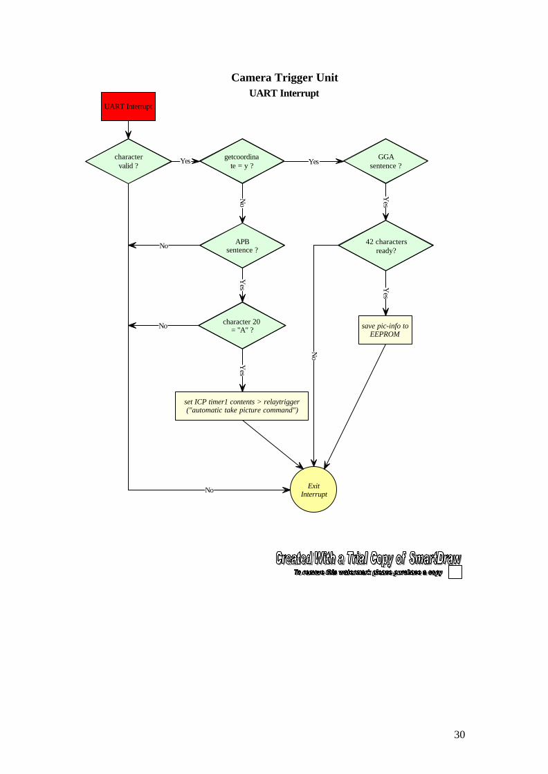
3.2.3. UART Interrupt
The UART interrupt contains one big part of the total code of the program. Thisinterrupt gets fired every time a character is received by the microcontroller. The GPSsends roughly 200 characters every second. Received characters are stored in strings(string is an array of chars with a terminating null character) and the code filters outonly specific parts of the GPS’s NMEA transmission. For the camera trigger unit thetwo NMEA sentences of interest are GGA and APB.
The APB sentence (Autopilot Sentence “B”)
The information extracted from this sentence tells the microcontroller if the UAV hasentered the “arrival circle”.
1 2 3 4 5 6 7 8 9 10 11 121314$GPAPB,A,A,0.0,L,N,A,,357.3,M,SIM002,347.8,M,,,*6A
1 Status2 Status3 Magnitude of XTE4 Direction to Steer (Left/Right)5 XTE units (N = Nautical Miles)6 A = Arrival Circle Entered7 A = Perpendicular Passed at Waypoint
8-9 Bearing origin to destination10 Destination waypoint ID

13
11-12 Bearing, present position to destination13-14 Heading to steer to destination waypoint
Table 4. The APB sentence contains information for navigation towards a specific waypoint.
This arrival circle has a radius of 50 m from the centre of the waypoint. When theGPS is within this imaginary circle it sets the character A in the 6th field of the APBsentence. The field filtered by the microcontroller is in this case only a character.When the APB sentence is detected the microcontroller awaits character number 20.It might seem unsafe to extract information this way, and in fact it is. But for thisparticular sentence, up to this field the number of characters remains always the same.The maximum value of the XTE field for example is 9.9.
Since some fields are variable width, or may be omitted, the receiver shouldlocate the desired data fields by counting commas, rather than by character positionwithin the sentence. Code for such a function has been written [Appendix 2 – NMEAField Extracting Code] but not used with the microcontroller.If the UAV has entered the “arrival circle” then a “camera trigger” request is sent. Ifthe timer allows a new picture to be taken the necessary command byte will be sent tothe camera’s COM port.
3.2.4. Saving picture information to the EEPROMImmediately after a picture has being taken, the (getcoordinate) flag is set, that willcause the first received GGA sentence to be saved on the EEPROM. In fact only thefirst five fields of the GGA sentence are saved.
The GGA sentence (GPS Fix Data)
Information exctracted from this sentence reveal the exact location of the GPSreceiver. 1 2 3 4 5 6 7 8 9$GPGGA,124706.59,5923.8146,N,01803.3650,E,1,04,2.0,-0026,M,,,,*38
1 UTC of Position2-3 Latitude – (North/South)4-5 Longitude – (East/West)6 GPS Quality Indicator7 Number of satellites in use8 Horizontal dilution of precision9 Antenna altitude above/below MSL10 Units of antenna altitude11 Geoidal Separation12 Units of geoidal separation (M = Meters)13 Age of Differential GPS Data14 Differential reference station ID
Table 5. The GGA sentence contains information about the present position of the GPS unit.
The data fields saved on the EEPROM contain: the sentence ID (always the same),the exact time, and the exact coordinates over which the picture was taken. When this

14
data has been saved the getcoordinate flag is reset and the microcontroller resumesnormal program execution.Each time a picture is taken 64 additional bytes are saved to the EEPROM. With32kB and 64 bytes per picture, a total of 512 data picture-information blocks can besaved to memory.
3.2.5. Uploading picture information to a PCThe picture information saved in the EEPROM since the camera trigger device waspowered can be sent to a PC at any time. Just disconnect the camera and connect anull-modem cable to a PC running a COM port monitoring program, such asHyperterminal. The data is sent at 9600 bps, with no parity and one stopbit. In the leftyou will see a number which corresponds to the picture number in the camera. Thisassumes that the camera has been cleared from all its pictures before each flight.
Future improvements of this program could utilize the picture numberinformation directly from the cameras reply on the “get status” command. A programthat establishes a real two way communication between the camera and PC was in factwritten. But it was later removed from the code, due to the difficulty of connectingboth the GPS and camera to the microcontroller’s single UART device.
Figure 10. Screenshot from the HyperTerminal, showing the pic-info uploaded from EEPROMto PC, by the press of a button. The red boxes indicate the fields of interest, and their content.
Figure 9. The two COM ports of the camera trigger unit

15
Figure 11. Pictures over a small airfield taken from an experimental UAV.

16
4. Waypoint Direction Finder Unit
This unit attempts to steer a UAV towards a pre-programmed waypoint or along aroute of waypoints. The program filters the NMEA sentences of interest and generatesthe required PWM signal. This signal controls a servo which in turn controls theaileron of the UAV.
The coordinates of interest are programmed in the GPS as sequentialwaypoints using the "route" function. The steering of the aircraft is not handled interms of absolute coordinates, but in terms of current heading and bearing. When theheading is equal to the bearing then aircraft is heading straight towards the waypoint.
The microcontroller’s task is twofold:• filter out the NMEA sentences of interest sent by the GPS.• use this information to generate a square wave (PWM) for a servo.
The microcontroller listens out for the RMB and the RMC sentences sent by the GPSreceiver once every second. The APB sentence could very probably also be used,because it contains the required information into a single sentence, thus makingfiltering a bit simpler.
The RMB sentence ( Generic Navigation Information )
The information extracted from this sentence includes direction to steer and bearing. 1 2 3 4 5 6 7 8 9$GPRMB,A,0.00,L,SIM001,SIM002,5923.8461,N,01803.3590,E,0010 11 12 13 140.0,350.,021.7,A*13
1 Status2-3 XTE in nautical miles – direction to steer4 Origin Waypoint ID5 Destination waypoint ID
6-7 Destination Waypoint Latitude (N/S)8-9 Destination Waypoint Longitude (E/W)10 Range nautical miles11 Bearing, True, Great Circle, Present Fix to Dest Wpt12 Closing velocity to destination (knots)13 Arrival (perpendicular at waypoint)14 Checksum
Table 6. Information extracted from the RMB sentence includes direction to steer and bearing.
The RMC sentence ( Transit Specific )
The only information extracted from this sentence is bearing. 1 2 3 4 5 6 7 8$GPRMC,124705.19,A,5923.8061,N,01803.3652,E,21.7,357.2,071002,03.,E*6F
1 Time, UTC of position fix

17
2 Status3-4 Latitude (N/S)5-6 Longitude (E/W)7 Speed over ground (knots)8 Course over ground (degrees)9 Date (ddmmyy)10 Magnetic Variation (degrees)11 Magnetic Variation (sense, E/W)12 Checksum
Table 7. Format of an RMC sentence.
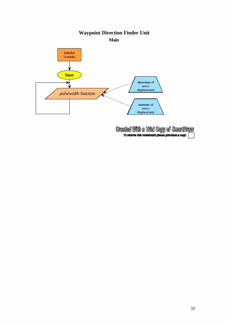
4.1. Waypoint Direction Finder Program FlowEvery second the GPS sends “bearing”, “heading” and “direction to steer”information through the COM port as NMEA sentences. The microcontroller receivesthese sentences and filters out only the required fields. These information fields aresent as parameters to the “degreestowpt” function which calculates the difference
in degrees betweenheading and bearing.The function thenreturns the resultwhich is used to judgehow much the servolever has to bedeviated from itscentral position inorder to change thecurrent heading of theUAV so that itmatches the bearing.Remember that whenheading and bearing
are equal, the aircraft is on the right path to its destination. The direction to steer is ofcourse used to decide in which direction to move the servo lever.The PWM signal generated on one of the microcontroller’s pins is linearlyproportional to the deviation from the waypoint. A deviation of more than 90 degrees,between heading and bearing, results in a full scale deviation of the servo lever.
4.2. Future improvementsIn the present design the (PWM) pulse is generated purely by software. Instead ofgenerating the PWM within the main’s while-loop, the microcontroller’s built inPWM support could be used. This will reduce the microcontroller’s load substantially,as well as increase the accuracy of the pulse.
Figure 12. Navigation principal for waypoint direction finder unit.

18
5. Altimeter / Altitude Hold Unit
This section describes how to construct an altimeter and explains how it could bemodified for stabilizing a UAV to a certain altitude. The theoretical accuracy of thealtimeter is calculated, and suggestions for increasing it are provided.
To illustrate the effects of pressure consider a diver, diving into the sea. As thedepth increases, the pressure exerted on the diver’s body increases. Similarly ouratmosphere could be compared to a gigantic sea of air, with a person standing at thesea bed. The sea bed in this example represents the earth. Air pressure is caused bythe weight of air pressing down on the earth. Earth’s gravity, of course, causes thedownward force that we know as “weight”. Since the pressure depends on the amountof air above the point where you are measuring the pressure, the pressure falls as yougo higher. Atmospheric pressure is inversely proportional to altitude. As altitudeincreases pressure decreases. The air pressure changes also with the weather. For agiven location during the course of the day the air pressure may change considerablydepending on the weather. An altimeter that measures altitude by measuring pressure,will therefore need to be calibrated in regular intervals.
This altimeter uses atmospheric pressure to calculate the altitude and it can becalibrated to correct for pressure variations. The interface to the user is three buttonsand an LCD. The buttons are used for calibration purposes. Two of the buttons allowthe sea level (reference) pressure to be increased, or decreased by steps of one hPa.When the power is disconnected this calibration is lost, unless the third “save” buttonis pressed. This button saves the reference pressure shown on the LCD to theEEPROM. The next time the unit is powered; the last saved sea-level pressure isretrieved from the EEPROM memory, displayed on the LCD and used for altitudecalculations. For measuring altitude a single calibration is not enough. Just likeairplane pilots, the latest sea level pressure for the area will have to be obtained andfed into the altimeter. This information for virtually any location can be obtained fromthe local weather station, or from web-based weather services. (See Internet Linkssection) The atmospheric pressure can vary quite a bit during a 24 hour period, and ifit is not kept up to date in the altimeter, the reading will be false.
At sea level the atmospheric pressure is on average 101.3 kPa. This value is notconstant, it can vary by approximately ±5% between so-called high and low pressuresystems.
5.1. Pressure SensorThe pressure sensor used is the MPX5100 manufactured byMotorola. [Figure 13] It can sense pressures from 115kPa to15kPa. The pressure can be measured indirectly at theoutput of the sensor as an analogue voltage which variesbetween 4.7V to 0.2 V. The linear equation which relatespressure to voltage is:
Since themicrocontroller cannot work with analogue levels, an ADconverter has to be used.
Figure 13. MPX5100AP
pressure sensor
Vout = 5(PÍ0.009-0.095) [5.1]

19
5.2. Analogue to Digital ConverterThe ADC used is the MAX187 manufactured by Maxim. It is a 12-bit successiveapproximation converter, used to convert an analogue voltage from the pressuresensor to a 12 bit serial stream. It is designed to interface and communicate with amicrocontroller, and is therefore suitable for this application. The result of eachconversion is sent upon request to the microcontroller through an SPI interface. Thepicture below shows the serial data stream going from the ADC to the microcontrollerin more detail. The 12 bit conversion result is read from the ADC, two bytes at thetime. The data is then processed as shown below by shifting various bits and storingthe final result in the variable “adcdig”.
Figure 14. Voltage Output from MPX5100 as a function of pressure
Volts

20
Table 8. Details of the SPI communication between ADC and microcontroller.
5.3. Altimeter Program FlowThis program is also interrupt driven, but with a single interrupt. Most of the time it isin an idle state, waiting for the timer interrupts to be fired. When an interrupt occurs itjumps to the timer interrupt handling routine. A sampling request is sent to the ADCthrough the SPI, which sends the result of the conversion back to the microcontrollerthrough the same interface. This sample is then added to a variable. Subsequentpressure samples are all added to the same variable. When fifteen samples have beenacquired the program flow is redirected to a part of the code that divides this variableby fifteen. The LCD then updates the local pressure and altitude. We now have theaverage value of fifteen samples all taken with evenly spaced intervals from eachother.
5.4. Altitude from PressureTo keep the UAV steady on a certain altitude, knowing the actual altitude, in meters,above the ground (or sea level) is not necessary. Pressure measurement is less trivialthan altitude measurement. Therefore since altitude and pressure are related, it isenough to try to stabilize the UAV to a certain pressure. Despite this, below anexplanation is given of how this conversion could be done.
The relationship between pressure and the voltage from the sensor output islinear. This makes the sensor a very accurate device for measuring atmosphericpressure over a vast altitude range. Unfortunately the relationship between altitudeand pressure is not linear, although at very low altitudes (below 1 km) it could beconsidered as such. For converting from local pressure (refered to as QFE inaeronautics) and sea level pressure (QNH) to altitude the following formula is used.Since the ratio of the two pressures is taken, any unit can be used.
−
×= 11.43634)(
190255.0
pressure
qnh
local
sealevelmaltitude
Equation 1. Converts sea level pressure and local pressure to an altitude

21
In C code this formula looks like this:
43634.1*(pow((qnh/pressure),0.190255)-1);
The “float pow(float x, float y)” math function, returns x raised to the powerof y. For the AT90S8515, the formula above, when compiled into machine language,results in a 30% increase of program memory.
5.5. AccuracyThe ½ km closest to the earth the pressure drops by 1 hpa for every increase inaltitude by eight meters. From the pressure sensor’s perspective a 1 hpa pressurevariation corresponds to a 4.5mV change. This in turn means that a one meter changein altitude causes an equivalent change in output voltage of roughly 0.6 mV.4.5/8 = 0.5625 mV/m.
If the ADC is set to convert voltages between zero and five volts: 5/0.006 =8333 levels would be required to be distinguished by an ADC if one meter accuracy isrequired. Since a 13bit ADC can distinguish between 2^13 = 8192 levels, a 13 bitADC is required if resolution of 1 meter is desired for the specified parameters
Accuracy can be increased in a number of ways. By looking at the table [Table 8]above, it would be easy to think that this can be done simply by substituting the 12-bitADC with a 14 or 16 bit ADC. Although simple, this approach is not recommended,not only because ADCs of such resolution are very expensive, but because there issomething that is fundamentally wrong with this setup, which doesn’t make full use ofthe resolution provided by the ADC.
5.6. Signal ConditioningThe problem is that for low level altitude measurements a very large part of theADC’s analogue conversion range (0 to 5V) is never used. A definitely cheaperapproach would be to keep the existing ADC and to use some analogue signalconditioning. The goal is to make full use of the 0-5 Volt span provided by the ADC.Signal conditioning consisting of basic amplifier circuits could be developed toenhance the part of the span that is mostly used, and “removing” part of the span that
ADC bitresolution
Theoretical accuracy inmeters
8 349 1710 8.711 4.312 2.1713 1.0814 0.515 0.2716 0.14
Table 9. Accuracy in meters for different ADCs, consideringADC voltage input varies between zero and five Volts, and
pressure sensor sensitivity is 4.5 mV per hPa.

22
is rarely or never used. This will mean that the altimeter would not be able to measureextremely low/high altitudes. But simultaneously the accuracy of the measuredaltitude within the new reduced altitude range would increase dramatically.
Unfortunately the construction of such a signal conditioning circuit is not verystraightforward, due to the nature of analogue electronics. The circuit has to besimulated repeated times. It must then be built with high precision components, andfinally verified with physical tests.
Figure 15. Theoretical explanation of how the accuracy could be increased with signalconditioning .
5.7. Future ImprovementsWhen the difficult task of acquiring the altitude (or pressure) is accomplished, it isrelatively easy to use this information to stabilize the UAV to a predefined altitude. Aservo arrangement similar to the one used with the “Waypoint Direction Finder Unit”could be used. This time instead of controlling the ailerons, the elevator on the tail ofthe UAV would have to be controlled. The microcontroller would have to repeatedlycompare the current altitude to the programmed altitude in a feedback loop, and fromthere deduct if it has to ascend or descend to reach the desired pre-programmedaltitude. Note that in a real aircraft, or UAV, all aircraft dynamics involved have tobe taken into consideration.
Figure 16. Basic description of altimeter altitude hold,feedback loop arrangement.
23
D. Conclusion.The camera triggering unit meets all requirements, as it offers not only manual, butalso an advanced automatic triggering option. An additional feature is the capabilityof saving the coordinates of locations photographed by the camera.
The waypoint direction finder unit also meets the requirements. Thedatastream sent from the GPS is successfully filtered. Extracted informationgenerates a signal which points the servo lever correctly towards the currentwaypoint.
The altimeter successfully determines the altitude. The requirements were fullymet though, as it does not (at present time) provide a way of stabilizing the aircraft toa certain altitude. However a description of how this could be accomplished is given.
This project proved to be very educative, because it covered many areas ofmodern electronic design. It did not deal strictly with software or hardware, but acombination of both. It was interesting follow the evolution of an electronic device inall its phases, from an idea to an actual product.
With modern electronic products becoming more and more digitalized,software development for microcontrollers is becoming an important aspect of theelectronics of today and tomorrow.

24
E. AbbreviationsADC Analog to Digital ConverterEEPROM Electronically Erasable Programmable Read Only MemoryGPS Global Positioning SystemICP Input Capture PinLCD Liquid Crystal DisplayMIPS Million Instructions Per SecondNMEA National Marine Electronics AssociationPC Personal ComputerPCB Printed Circuit BoardPWM Pulse Width ModulationQFE Local pressureQNH Sea level pressureRAM Random Access MemoryRISC Reduced Instruction Set ComputerSPI Synchronous Peripheral InterfaceUART Universal Asynchronous Receiver TransmitterUAV Unmanned Aerial VehicleXTE Cross Track Error

25
F. Sources1. Jan Axelson & Janet Louise Axelson, The Microcontroller Idea Book: Circuits,
Programs & Applications Featuring the 8052-Basic Single-Chip Computer, 1st edition(January 1997) p1.
2. John Iovine, PIC Microcontroller Project Book, (May 2000) p1.3. NMEA Sentence Information,
<http://home.mira.net/~gnb/gps/nmea.html>
4. Serial Peripheral Interface (SPI),<http://web.media.mit.edu/~fredm/papers/mb/node38.htmll>
5. Kodak DC3400 (Camera Protocol Information),<http://camcontroller.sourceforge.net/dc3400.html>
6. Digital Altimeter<http://www.qsl.net/ok2xdx/Altimeter/altimeter.html>
G. Internet LinksMicropilothttp://www.micropilot.com
RISC Architecturehttp://cse.stanford.edu/class/sophomore-college/projects-00/risc/
National Weather Service, Internet Weather Sourcehttp://weather.noaa.gov/index.html
Microcontrollers Overviewhttp://www.ami.bolton.ac.uk/courseware/micros/overview.html
CodeVision AVR – C-compliler for AVR Microcontrollershttp://www.hpinfotech.ro/
Digital Photography by Radio Controlhttp://www.rc-soar.com/tech/dwaerialphoto.htm
Weather Basicshttp://www.usatoday.com/weather/tg/whighlow/whighlow.htm
Ricoh RDC-2E Serial Line Protocol (not Kodak Protocol)http://www.netspace.net.au/~bmiller/linux/rdc2e/protocol.html
Altimeterhttp://home.t-online.de/home/Matthias.Stehr/hoehe.htm
H. Product SheetsThe latest product sheets for the microcontrollers used in this project can be obtainedfrom Atmel.Atmel 8 bit RISC AVR Microcontrollershttp://www.atmel.com/atmel/products/prod23.htm

26
I. Appendix (Program Flow Charts)
a. Camera Trigger UnitMainICP & Timer InterruptUART Interrupt
b. Waypoint Direction Finder UnitMainUART Interrupt
c. Altimeter / Altitude Hold UnitMainTimer Interrupt

27

28
InitializeVariables
ICP timer1content >
pulsetrigger?
Camera Trigger Unit
Yes
Main
No
send "take picture" command toCOM port
Start
"Send to PC"button pressed?
send picture information toCOM port
Yes
No

29
ICP Interrupt
fallingedge?
Camera Trigger Unit
Yes
ExitInterrupt
ICP Interrupt
No
save timer1 contentschange trigger to rising edge
clear timer1 contentschange trigger to falling edge
Timer0Interrupt
wait = 0 ?
Yes
ExitInterrupt
No
decrement wait
Timer0 Interrupt
30
UART Interrupt
charactervalid ?
Camera Trigger Unit
getcoordinate = y ?
APBsentence ?
character 20= "A" ?
Yes
No
Yes
set ICP timer1 contents > relaytrigger("automatic take picture command")
Yes
ExitInterrupt
YesGGA
sentence ?Y
es
42 charactersready?
save pic-info toEEPROM
Yes
UART Interrupt
No
No
No
No
31
InitializeVariables
Waypoint Direction Finder UnitMain
Start
pulsewidth function
amount ofservo
displacement
direction ofservo
displacement

32
UART Interrupt
charactervalid ?
Waypoint Direction Finder Unit
NMEA sentence= $xxxMx ?
No
NoExitInterrupt
Yes
Yes
exctractbearing
UART Interrupt
Yes
No
No
sentence =$GPRMC
NMEA sentence= $xxxxB ?
sentence =$GPRMB
have 34charactersarrived?
character = $?
Yes
exctractheading
degreestowpt function
amount ofservo
displacement
No
exctractdirection to
steer
direction ofservo
displacement
Yes

33
QNH- Buttonpressed?
Altitude MeterMain
QNH+ Buttonpressed?
Save QNHButton
pressed ?
No
No
showqnh function
Retrieve last QNH fromEEPROM and show on
LCD
InitializeVariables
Start
Yes saveqnh function
decrement QNHYes
updatelcd function
increment QNHYes
updatelcd function

34
Timer Interrupt
Altimeter / Altitude Hold UnitTimer Interrupt
timervar=255 ?
Yes
No
timervar =16,32,48,64,80,96,
112,128,144,160,176,192,208,224,240
?
save instantaneouspressure to var:" adcdigmean"
Yes
No
ExitInterrupt
15adcdigmean error
compensationshow pressure
on LCD
show altitudeon LCD
−
×= 11.43634)(
190255.0
pressure
qnh
local
sealevelmaltitude

35
J. Appendix (C-Code)
a. Altitude Hold
/* Altimeter v1.0CPU = AT90S8515XTAL = 8MHzPROG MEM USE = 62% (?%)PERIPHERALS 1. 12-bit ADC (MAX187) 2. pressure sensor (MPX5100AP)NOTES: Samples from ADC 15 times with equal intervals during a 2 secondperiodand then updates the LCD.IMPORTANT: use a small capacitor on pressure sensor outputsAUTHOR = Alex SkafidasUPDATE = 4 October 2002PINS:3 CPU - 1K res to gnd + switch4 CPU - 1 EEPROM (spi CS)5 CPU - 7 ADC (spi CS)6 CPU - 5 EEPROM (spi MOSI)7 CPU - 6 ADC - 2 EEPROM (spi MISO)8 CPU - 8 ADC - 6 EEPROM (spi clock)10 CPU - Vcc15 CPU - 6 LCD16 CPU - 4 LCD20 CPU - Gnd40 CPU - Vcc4 EEPROM - Gnd8 EEPROM - Vcc7 EEPROM - Vcc*/
#include <io8515v.h>#include <macros.h>#include <string.h>#include <stdlib.h>#include <math.h>#include <eeprom.h>
// interrupt vector number valid for 8515#pragma interrupt_handlertimer_interrupt:8
#define RW 4 // not used - connect to gnd#define E 5#define RS 6#define CS_ADC 4 // PB#define CS_EEP 3#define REFRESHRATE 0x04
/* Variables */char ready =1;char eepromdata;char bytehi;char bytelo;char timervar;char adcdigalpha[8];char eepromadress = 0;unsigned int qnh;signed int calc;unsigned int adcdig;unsigned int adcdigmean;

36
unsigned int pressure;
/* Prototypes */void LCD_init(void);void LCD_clear(void);void Delay(int times);void LCD_putstr(char* str);void LCD_goto(char y, char x);void LCD_putch(char rs, char rw, char data);void SpiInit(void);void port_init(void);void init_devices(void);void eepromread(void);char SpiReadByte(char spitx);void showqnh(void);void saveqnh(void);void updatelcd(void);
void main( void )init_devices();// Formatted for 4x20 LCDLCD_putstr("pressure hPa altitude m");LCD_goto(2,1);LCD_putstr("QNH: ");showqnh();SEI();while (1) if (((PIND & BIT(2)) == BIT(2) && ready ==1)) ready = 0; qnh = qnh + 10; updatelcd(); else if (((PIND & BIT(3)) == BIT(3) && ready ==1)) ready = 0; qnh = qnh -10; updatelcd(); else if (((PIND & BIT(4)) == BIT(4) && ready ==1)) TCCR0 |= 0x00; CLI(); EEPROM_WRITE(0x1,qnh); TCCR0 |= REFRESHRATE; SEI();
void updatelcd(void)itoa(adcdigalpha,qnh,10);adcdigalpha[4]='\0';LCD_goto(2,6);LCD_putstr(adcdigalpha);
void showqnh(void)EEPROM_READ(0x1,qnh);if ((qnh < 10000) || (qnh > 11500)) qnh = 10350; EEPROM_WRITE(0x1,qnh);

37
itoa(adcdigalpha,qnh,10);adcdigalpha[4]='\0';LCD_goto(2,6);LCD_putstr(adcdigalpha);
void timer_interrupt (void)TCCR0 |= 0x00;timervar++;if (timervar == 255) char decim; char i;
// pressure from ADC reading adcdigmean = adcdigmean / 15; pressure = ((((adcdigmean/4095.0)+0.095)/0.009)*100); pressure = pressure - 141; itoa(adcdigalpha,pressure,10);
// format pressure, with decimal point decim = adcdigalpha[4]; adcdigalpha[4]='\0'; // Bug if pressure is below 1000 hpa ? LCD_goto(1,10); LCD_putstr(adcdigalpha); LCD_putch(1,0,'.'); LCD_putch(1,0,decim);
// pressure to altitude calc = abs((43634.1*(pow(((qnh+1.0)/pressure),0.190255)-1)));
LCD_goto(3,10);
// Set sign for altitude if (qnh < pressure) LCD_putch(1,0,'-'); else LCD_putch(1,0,'+');
itoa(adcdigalpha,calc,10); LCD_putstr(adcdigalpha); LCD_putstr(" "); adcdigmean = 0; timervar = 0;
ready = 1; // enable buttons else if ((timervar & 0x0F) == 0x0F) PORTB &= ~BIT(CS_ADC); // turn off CS bytehi = SpiReadByte(0x00); // CS should NOT go LOW between thesereadings bytelo = SpiReadByte(0x00); PORTB |= BIT(CS_ADC); // turn on CS adcdig = ((int)(bytehi << 5) | (bytelo >> 3)); adcdig = adcdig - 0x1000;
adcdigmean = adcdigmean + adcdig; TCCR0 |= REFRESHRATE;
void init_devices(void) CLI(); port_init(); SpiInit();

38
UCR = 0x00; //disable while setting baud rate UBRR = 0x33; //set baud rate UCR = 0x08; //enable
LCD_init(); LCD_clear();
TCCR0 |= REFRESHRATE; TIMSK |= 0x02; // timer 0 overflow interrupt enable
void port_init(void) PORTA = 0xFF; // 7654 3210 DDRA = 0xFF; PORTB = 0xFB; // 1111 1011 DDRB = 0xFB; // 1111 1011 PORTC = 0xFF; DDRC = 0xFF; PORTD = 0xE3; // 1110 0011 DDRD = 0xE3; // 1110 0011
// SPI clock rate: 62500hz
void SpiInit(void) // SPI can ONLY use port B DDRB |= 0xB0; // Set SCK, MOSI & SS as outputs PORTB &= 0x5F; // clear bits MOSI, & SCK SPCR = 0x53; // + SPE + MSTR; Write to control register
/*** SpiReadByte() first writes a byte (a dummy, since** that byte is to generate clock signals to "poll" home** the byte from the slave. The function returns the** received byte.*/char SpiReadByte(char spitx) SPDR = spitx; while (!(SPSR & 0x80)); return SPDR;
For LCD and Delay subroutines see Appendix 2. Common Subroutines (LCD,Delay)

39
b. Waypoint Direction Finder Unit
/* Waypoint Direction Finder v1.0CPU = AT90S2313XTAL = 8MHzPROG MEM USE = 25% (22%)NOTES: MAJOR MODIFICATIONSAUTHOR = Alex SkafidasUPDATE = 30 July 2002
#include <io8515v.h>#include <macros.h>#include <string.h>#include <stdlib.h>
// always include math.h before calling any floating point functions// otherwise your program may not work
#pragma interrupt_handler UART_RX_interrupt:10
/* UART Buffer Defines */
#define DOLLAR '$'
#define FALSE 0#define TRUE 1
#define RS 6#define E 5#define RW 4
#define UART_RX_BUFFER_SIZE 33
/* Static Variables */
unsigned int charcount = 0;char UART_RxHead = 0;static char UART_RxBuf[UART_RX_BUFFER_SIZE];
char direction;int answer;
int headint;int bearint;
/* Prototypes */
void LCD_init(void);void LCD_clear(void);void Delay(char times);void LCD_goto(char y, char x);void LCD_putstr(char* str);unsigned char ReceiveByte( void );void InitUART( unsigned char baudrate );int degreestowpt(int, int);void LCD_putch(char rs, char rw, char data);void pulsewidth(int times);
void port_init(void) PORTA = 0xFF; DDRA = 0xFF; PORTB = 0xFF; DDRB = 0xFF; PORTC = 0xFF; DDRC = 0xFF;

40
PORTD = 0x7E; DDRD = 0x7E;
void InitUART( unsigned char baudrate ) unsigned char x; UBRR = baudrate; // set the baud rate // enable UART receiver, and receiveinterrupt UCR = ( (1<<RXCIE) | (1<<RXEN) ); x = 0; // flush receive buffer UART_RxHead = x;
/* interrupt handler */void UART_RX_interrupt( void ) unsigned char data; unsigned char tmphead;
char answer2[4]; static char bearing[4]; static char heading[4];
if ((USR & BIT(FE)) == BIT(FE) ) // if received byte is weird, discard return;
UCR &= ~BIT(RXCIE); // disable all interrupts
data = UDR; // read the received data UART_RxBuf[UART_RxHead] = data; // store received data in buffer
if ( UART_RxHead + 1 == UART_RX_BUFFER_SIZE) if (UART_RxBuf[4] == 'M') if (UART_RxBuf[5] == 'B') // RMB - bearing to waypoint UART_RxBuf[0] = '?'; UART_RxBuf[UART_RX_BUFFER_SIZE] = '\0';//LCD_putstr(UART_RxBuf); // print RMB sentence on LCD //arrived = UART_RxBuf[39]; direction = UART_RxBuf[14];
strncpy(bearing, UART_RxBuf + 28, 3); //LCD_goto(2,1); //LCD_putstr(bearing); // print bearing on LCD
bearing[3]='\0'; bearint = atoi(bearing);
UART_RxHead = 0; tmphead = 0; charcount = 0; else // RMC - heading //LCD_goto(1,1); UART_RxBuf[0] = '?'; UART_RxBuf[UART_RX_BUFFER_SIZE] = '\0';// place a nullcharacter at end //LCD_putstr(UART_RxBuf); // print RMCsentence on LCD

41
strncpy(heading, UART_RxBuf + 16, 3); //LCD_goto(2,7); //LCD_putstr(heading); // print heading on LCD
heading[3]='\0'; // put null on 4thcharacter for atoi function headint = atoi(heading); // atoi returns 0 onerror
answer = degreestowpt(headint, bearint); //itoa(answer2,answer,10); //LCD_goto(2,15); //LCD_putstr(answer2); //LCD_putch(1,0,direction); //LCD_putstr(" ");
UART_RxHead = 0; tmphead = 0; charcount = 0;
if ((answer > 50) && ((PIND & BIT(7)) != BIT(7))) answer = 50; // pulse 1.00 - 2.00 else if ((answer > 50) && ((PIND & BIT(7)) == BIT(7))) answer = 25; // pulse 1.25 - 1.75 else UART_RxHead = 0; tmphead = 0; charcount = 0; else if (UART_RxBuf[0] == DOLLAR) charcount++; if (charcount < 16 || charcount > 48) tmphead = ( UART_RxHead + 1 ); UART_RxHead = tmphead;
UCR |= BIT(RXCIE); // restore interrupts - cleared when UDR is read?
void main( void ) InitUART( 103 ); // for 4800 baud, UBR=51 for 4MHz, UBR=103 for 8MHz port_init(); // needed - specify inputs & outputs LCD_init(); LCD_clear(); LCD_putstr("check com port2");
_SEI(); // enable global interrupts => enable UART interrupts while ( 1 ) if (direction == 'L') pulsewidth( 150 - answer); else if (direction == 'R') pulsewidth( 150 + answer);
void pulsewidth(int times)

42
char a;unsigned b;int stabilize;char answer3[4];itoa(answer3,times,10);LCD_goto(4,1);LCD_putstr(answer3);for (stabilize = 0; stabilize < 5; stabilize++) UCR &= ~BIT(RXCIE); //dis UART interrupt PORTD |= BIT(PD3); for (a=0; a < times; a++) for (b=0; b < 5; b++); // 2 for 4MHz and 5 for 8MHz PORTD &= ~BIT(PD3); UCR |= BIT(RXCIE); // restore UART interrupts Delay(12);
int degreestowpt (int head, int bear)int deg2wpt;
if ( abs(head - bear) < 180) deg2wpt = abs(head - bear);else // if abs( HDG - BRG) > 180 if ( head > 180) deg2wpt = ((360 - head) + bear); else if (head < 180) deg2wpt = ((360 - bear) + head); return deg2wpt;
For LCD and Delay subroutines see Appendix 2. Common Subroutines (LCD,Delay)

43
c. Camera Trigger Unit
/* GPS & Pulse Camera Trigger v1.0CPU = AT90S8515XTAL = 8MHzPROG MEM USE = 25% (22%)PERIPHERALS 1. 32 KB EEPROM (M95256)NOTES: MAJOR MODIFICATIONSAUTHOR = Alex SkafidasUPDATE = 2 November 2002
interrupt vectors are for 8515 ONLY2313 to 8515-file header-int vector numbers-LCD port - & RS/E PINS !!!-PORT INIT !!!
count: array = 45 + 5 char = 7 int = 3 (*2) --------- 63 bytes of RAM ?*/
#include <io8515v.h>#include <macros.h>#include <string.h>#include <stdlib.h>
#pragmainterrupt_handlericp_interrupt:4#pragma interrupt_handler timer_overflow:8#pragma interrupt_handler UART_RX_interrupt:10
#define RW 4 // not used - connect to gnd#define E 5 // PD#define RS 6#define relaytriggerlow 230#define relaytriggerhigh 238#define DOLLAR '$'#define UART_RX_BUFFER_SIZE 45#define REFRESHRATE 0x05#define CS_EEP 3
char UART_RxBuf[UART_RX_BUFFER_SIZE];char timercountalpha[5];char ready = 1;char head;char drop = 0;char emptydata;char picturesleft = 99;char getcoordinate = 'n';char countdown = 6;char timercount1 = 150;char eepadrlow;char eepadrhig;unsigned int wait = 200;unsigned int eepromadress = 0;
void LCD_init(void);void LCD_clear(void);void Delay(int times);void LCD_goto(char y, char x);void LCD_putstr(char* str);unsigned char ReceiveByte(void);

44
void LCD_putch(char rs, char rw, char data);void init_devices(void);void inputcaptureinit(void);void icp_interrupt(void);void timer_overflow (void);void SpiInit(void);char SpiReadByte(char spitx);
void port_init(void) PORTA = 0xFF; // 7654 3210 DDRA = 0xFF; PORTB = 0xFB; // 1111 1011 DDRB = 0xFB; // 1111 1011 PORTC = 0xFF; DDRC = 0xFF; PORTD = 0xE7; // 1110 0111 DDRD = 0xE7; // 1110 0111
void timer_overflow (void)TCCR1B &= ~0x03; // stop timer - dangerous when return is executedif (wait == 0) PORTD &= ~BIT(PD2); TCCR1B |= 0x03; // restore timer return; else wait--; timercount1 = 111; PORTD |= BIT(PD2); TCCR1B |= 0x03; // restore timervoid InitUART( unsigned char baudrate )UBRR = baudrate;UCR = 0x98;
void inputcaptureinit(void)TIFR |= (1 << ICF1);TCCR1B |= (1 << CS11) | ( 1 << CS10) | (1 << ICNC1) | (1 << ICES1);TIMSK |= (1 << TICIE1);
void init_devices(void) CLI(); InitUART(51); port_init();
TCCR0 = REFRESHRATE; TIMSK |= 0x02; // timer0 overflow int enable
inputcaptureinit();
SpiInit();
LCD_init(); LCD_clear(); SEI();

45
void SpiInit(void)DDRB = 0xFD;PORTB = 0x00;SPCR = 0x53; // + SPE + MSTR; Write to control register
PORTB |= BIT(CS_EEP); // high toPORTB &= ~BIT(CS_EEP); // low transition for EEPROMPORTB |= BIT(CS_EEP);
void sendcommand (char command)putchar(command); // 0x7C = take pic, 0x7F = status requestputchar(0x00);putchar(0x00);putchar(0x00);putchar(0x00);putchar(0x00);putchar(0x00);putchar(0x1A);
void main( void ) init_devices(); LCD_goto(2,1); LCD_putstr("target: "); LCD_goto(1,1); LCD_putstr("pics: "); LCD_goto(1,10); LCD_putstr("trig: "); while(1) if ((PIND & BIT(3)) == BIT(3) ) char i; char j; char eepromdata; _CLI(); TCCR1B &= ~0x03; TCCR0 = 0x00; UCR &= ~BIT(RXCIE); // clear TIMSK &= ~BIT(TICIE1);
PORTB &= ~BIT(CS_EEP); // turn off CS SpiReadByte(0x03); // Read Data from Mem Array SpiReadByte(0x00); SpiReadByte(0x00);
for (j = 1; j < 10; j++) putchar(j + 0x30); putchar('='); for (i = 0; i <= 63; i++) eepromdata = SpiReadByte(0x00); putchar(eepromdata); putchar(0xA); // LF - LineFeed putchar(0xD); // CR – Carriage Return
PORTB |= BIT(CS_EEP); // turn on CS
ready = 0;
46
TCCR1B |= 0x03; TCCR0 = REFRESHRATE; TIMSK |= BIT(TICIE1); UCR |= BIT(RXCIE); _SEI();
if ( (timercount1 > relaytriggerlow) && (wait == 0) && (timercount1 < relaytriggerhigh)) //&& (picturesleft != 1) TCCR1B &= ~0x03; TCCR0 = 0x00; UCR &= ~BIT(RXCIE); TIMSK &= ~BIT(TICIE1);
sendcommand(0x7C); picturesleft--;
LCD_goto(1,7); itoa(timercountalpha,picturesleft,10); LCD_putstr(timercountalpha); LCD_goto(1,18); itoa(timercountalpha,timercount1,10); LCD_putstr(timercountalpha); LCD_goto(1,16); LCD_putch(1,0,' ');
wait = 300; getcoordinate = 'y'; timercount1 = 144;
TCCR1B |= 0x03; TCCR0 = REFRESHRATE; TIMSK |= BIT(TICIE1); UCR |= BIT(RXCIE);
void UART_RX_interrupt( void )TCCR1B &= ~0x03; // stop timerTCCR0 = 0x00;
if ((USR & BIT(FE)) == BIT(FE) ) return;
emptydata = UDR;UART_RxBuf[head] = emptydata;
if (emptydata == DOLLAR) head = 0;
if ((UART_RxBuf[0] == DOLLAR) && (head <= 6))head++;return;
if (getcoordinate == 'n') if ((UART_RxBuf[4] == 'P') && (UART_RxBuf[5] == 'B') && (head < 20)) head++; if (head == 20) head++; UART_RxBuf[21]='\0';

47
if (emptydata == 'A') LCD_goto(1,16); LCD_putch(1,0,emptydata); PORTD ^= BIT(PD2); timercount1 = 235; else timercount1 = 149; else if (getcoordinate == 'y') char i; if ((UART_RxBuf[4] == 'G') && (UART_RxBuf[5] == 'A') && (head < 42)) head++; if (head == 42) head++; LCD_goto(2,9); UART_RxBuf[42]='\0'; LCD_putstr(&UART_RxBuf[16]);
eepadrlow = eepromadress & 0xff; eepadrhig = eepromadress >> 8;
// Save picture info to EEPROM PORTB &= ~BIT(CS_EEP); // turn off CS SpiReadByte(0x06); // Write Enable PORTB |= BIT(CS_EEP); // turn on Delay(20); PORTB &= ~BIT(CS_EEP); // turn off CS SpiReadByte(0x02); // Write Data to Mem Array SpiReadByte(eepadrhig); SpiReadByte(eepadrlow);
for (i = 0; i <= 42; i++) SpiReadByte(UART_RxBuf[i]); // data to save Delay(30);
for (i=43; i <= 63; i++) SpiReadByte('*'); Delay(30);
PORTB |= BIT(CS_EEP); // turn on CS
// Future Improvement: Add an end marker
ready = 1; getcoordinate = 'n'; eepromadress = eepromadress + 64; TCCR0 = REFRESHRATE;TCCR1B |= 0x03; // restore timer
char SpiReadByte(char spitx) SPDR = spitx; while (!(SPSR & 0x80)); return SPDR;

48
void icp_interrupt(void)TCCR1B &= ~0x03; // stop timerTCCR0 = 0x00;if (drop == 1) timercount1 = ICR1; TCCR1B |= (1 << ICES1); drop = 0; else drop = 1; TCNT1 = 0; TCCR1B &= ~(1 << ICES1); TCCR0 = REFRESHRATE;TCCR1B |= 0x03;
For LCD and Delay subroutines see Appendix 2. Common Subroutines (LCD,Delay)

49
d. Common Subroutines (LCD, Delay)
void Delay(int times)// with a 4 MHz clock times = [ms]// shortest delay is Delay(0) which gives aprox. 40 us (used for LCD) char a; unsigned int b;
if (times > 0) for (a = 0; a < times; a++) for (b = 1; b < 1454; b++)// every loop takes 5.5cc = 687.5 ns @8 MHz ; // (b < 1454 for 8 MHz) else for (a = 1; a < 128; a++) ;
void LCD_putch(char rs, char rw, char data) // for simple data (1,0,data) if (rs) PORTD |= BIT(RS); else PORTD &= ~BIT(RS);
if (rw) // not used: if-else can be removed PORTD |= BIT(RW); else PORTD &= ~BIT(RW);
PORTC = data; // LCD data is on port C
PORTD |= BIT(E); Delay(0); PORTD &= ~BIT(E); Delay(0);
void LCD_init(void) Delay(16); LCD_putch(0, 0, 0x30); // set to 8-bit interface Delay(5); // wait at least 4.1 ms LCD_putch(0, 0, 0x30); // set to 8-bit interface Delay(1); // wait 1ms LCD_putch(0, 0, 0x30); // set to 8-bit interface LCD_putch(0, 0, 0x38); LCD_putch(0, 0, 0x08); // display off LCD_putch(0, 0, 0x01); // display clear Delay(16); LCD_putch(0, 0, 0x06); LCD_putch(0, 0, 0x0E); // Turns on display and cursor
LCD_putch(0, 0, 0x02); Delay(16);
void LCD_clear(void) LCD_putch(0, 0, 0x01); Delay(16);

50
void LCD_putstr(char* str) char i = 0;
while(*(str+i) != '\0') LCD_putch(1, 0, *(str+i)); i++;
void LCD_goto(char y, char x) char DDRAM;
switch(y) case 1 : DDRAM = 0x00 + x - 1; break; case 2 : DDRAM = 0x40 + x - 1; break; case 3 : DDRAM = 0x14 + x - 1; break; case 4 : DDRAM = 0x54 + x - 1; break; DDRAM = DDRAM | 0x80; LCD_putch(0, 0, DDRAM);

51
e. NMEA field extracting code
Example. Recall that NMEA sentences have their information fields separated bycommas (the separator). This example explains how to use the program below toexctract fields (information between separators) from a string with separators.Since some fields are variable width, or may be omitted, desired data fields should belocated by counting commas, rather than by character position within the sentence.
To exctract the 2nd, 3rd and 4th field of this NMEA sentence:
$GPAPB,A,A,0.0,L,N,A,,357.3,M,SIM002,347.8,M,,,*6A
using the code below, you would have to assign the NMEA sentence the variablemystring. You then tell what fields should be exctracted. In this case we want fields2, 3 and 4.
We therefore use the following function:
void stringparse(int selectmin, int selectmax);
and request fields 2 to 4.
selectmin = first field to exctractselectmax = last field to exctract
stringparse(2, 4);
The function will parse the given string and will store the exctracted fields in anotherstring called info. The contents of this string will be:
info[] = ,A,A,0.0,
Note: If only one field needs to be exctracted, selectmin and selectmax are bothassigned the same “field-locator” number.
C-code.Created and compiled successfully in Borland C++ v5.02
String to parse: ”,alpha,bravo,charlie,delta,echo,fox,golf”Fields: ”,--1--,--2--,---3---,--4--,--5-,-6-,-7--”
#include <iostream.h>#include <string.h>#include <conio.h>
int character;int character2;
int selectmin;int selectmax;
int selectdata;int commacount;

52
char separator = ',';
char info[30];char count[]= " 1 2 3 4 5 6 7 ";char mystring[]= ",alpha,bravo,charlie,delta,echo,fox,golf,";
void stringparse(int selectmin, int selectmax);
main(void)while(1) clrscr(); cout << "Function for parsing strings using a variable separator\n\n\n"; cout << "[x x] - Select Substring\n\n"; cout << "[8 8] - Change Data Separator\n"; cout << "[9 9] - Exit\n\n\n"; cout << count << "\n"; cout << mystring << "\n\n\n"; cout << "Sting Length: " << strlen(mystring) << "\n"; cout << "Scanned Letters: " << character << "\n"; cout << "Separators Found: " << commacount << "\n"; cout << "Requested Data: " << info << "\n\n"; cout << "Select []" << separator << "[]" << separator << "[]: min(space) max\n";
character = 0; character2 = 0; selectdata = 0; commacount = 0;
cin >> selectmin; cin >> selectmax;
switch(selectmin) case 9: cout << "\n\n\nHave a nice DOS..."; cin.get(); cin.get(); return 0; case 8: cout << "\n\nEnter new data separator to use: "; cin >> separator; break; default: stringparse(selectmin,selectmax); break;
void stringparse(int selectmin, int selectmax)for (character = 0; character < strlen(mystring); character++) if (mystring[character] == separator) commacount++; if ( (commacount > selectmin-1) && (commacount < selectmax+1) ) info[character2] = mystring[character]; character2++; info[character2]=','; info[character2+1]='\0';

53
K. Appendix (Schematics)
Camera Trigger Unit
Schematic 1. Camera Trigger
Component List
SL1 ConnectorIC2 Max232IC3 ST95256IC4 AT90S8515X3 COM-port maleX4 COM-port maleR1 470 ΩR2 10 kΩD1 LED 3mmS1 Button (normally open)Q3 8 MHz crystal
C7-C10 10 uF, electrolytic

54
Waypoint Direction Finder
Schematic 2. Waypoint Direction Finder Unit
Component List
IC1 AT90S2313Q3 8 MHz crystalX1 COM-port maleSL1 ConnectorC8 10 uF, electrolytic

55
Altimeter
Schematic 3. Altimeter Unit
Component List
IC4 AT90S8515Q3 8 MHz crystal
MPX5100AP pressure sensorSL2 14 pin LCD ConnectorC8 10 uF, electrolytic
R2-R4 10 kΩS1-S3 Button (normally open)R1 Trim-potentiometerIC1 MAX187

56
L. Appendix (PCB)
PCB 1. Altimeter
PCB 2. Camera Trigger Unit