microcontroller based wireless automatic antenna ... · antenna positioning systems are necessary....
TRANSCRIPT
12 Surya Deo, Pankaj Rai,Arvind Kumar
International Journal of Electronics, Electrical and Computational System
IJEECS
ISSN 2348-117X
Volume 3, Issue 6
August 2014
MICROCONTROLLER BASED WIRELESS
AUTOMATIC ANTENNA POSITIONING SYSTEM
SURYA DEO CHOUDHARY*, PANKAJ RAI, ARVIND KUMAR, IRSHAD ALAM
Abstract
The automatic Antenna Positioning system primarily functions to identify the source of
signal. The signal may be of any type and any kind, it automatically identifies the presence of a
particular signal and the antenna will remain stationary as long as the signal link is established.
Whenever the signal link breaks between the antenna and the satellite or source the antenna revolves
continuously in search of the signal. This system also has advance connectivity with the
monitor/LCD screen to indicate the antenna position.
In this project the source of signal is simulated by an Infrared (IR) source. And a
corresponding IR receiver is used for detecting the signal. The receiver part includes one mono-
stable that improves the stability of the system, against the transient interruption and momentary
absence of the signal. The controller circuit is developed on a Microcontrollers–51-core micro
controller. This controller mainly searches the availability of the signal, whenever the signal is
found absent at the receiver. The controller drives the DC motor to rotate and this rotation goes on
till the receiver found the signal. The controller provides necessary signal to the motor driver on
which the antenna is mounted. The driver circuit provides adequate current and necessary voltage
level to drive the motor in turn to move the antenna.
The interfacing between the transmitter unit and the receiver unit is done through DTMF
Encoder and Decoder which gives the coding and decoding scheme that is flexible signaling scheme
with high reliability just as that used in telephone communication technology.
The transmitter used here employs FM technology which eliminates possibility of any
distortion. The receiver used here employs Super-Heterodyne FM receiver with automatic
amplification regulation and it is ensured that the whole system rejects distortion due to parasitic
modulation and demodulation.

13 Surya Deo, Pankaj Rai,Arvind Kumar
International Journal of Electronics, Electrical and Computational System
IJEECS
ISSN 2348-117X
Volume 3, Issue 6
August 2014
The decoded massage at the receiver unit is fed to the controller unit which after requisite
signal processing displays the position of the antenna by exhibiting the degree of rotation of the
antenna with respect to a certain reference point.
Objective of the project
In modern scientific world, there are threat perceptions to air defence from the enemy. Major
establishments such as government buildings and offices, various sites of industries, places of
financial importance, residence of ministers and VIP’s, heritage centres and tourist places and
pilgrimages need to be guarded against any possible attacks from the enemy. For this the air defence
system in and around these sites need to be monitored continuously through Radar Surveillance
System. A particular target object needs to be detected and monitored. For this the Automatic
Antenna Positioning Systems are necessary.
Details of project design
The design principles are based on simple phenomena. The tracking system has an antenna
which contains a receiver, a delay circuit and a base transmitter.
The receiver is placed at the center point of the antenna. Whenever the receiver receives a
signal with adequate strength, a logic high pulse is generated by a mono-stable configured around a
555 Timer.
To avoid interference and unnecessary triggering, a time delay is provided. And 8nos. of IR
receiver (photo diode) arranged around the antenna to detect the position of antenna.
All the receivers output are connected to the microcontroller through a signal conditioning
circuit for a compatible output to the Microcontroller.
The logic level is continuously checked with proper time delay. As long as the controller
senses the logic high the motor will stay at that place assuming the signal is available to the antenna
and the position of antenna will display on LCD in degrees.
14 Surya Deo, Pankaj Rai,Arvind Kumar
International Journal of Electronics, Electrical and Computational System
IJEECS
ISSN 2348-117X
Volume 3, Issue 6
August 2014
Whenever there is no signal or logic low level appearing, the controller will drive the motor
to search a signal i.e. logic high at the controller input port. The controller will continuously repeat
this process to track the antenna for a particular signal.
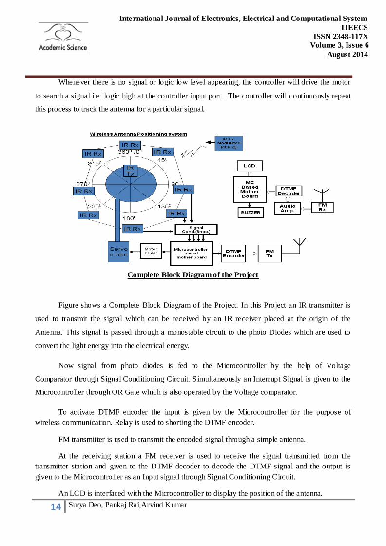
Complete Block Diagram of the Project
Figure shows a Complete Block Diagram of the Project. In this Project an IR transmitter is
used to transmit the signal which can be received by an IR receiver placed at the origin of the
Antenna. This signal is passed through a monostable circuit to the photo Diodes which are used to
convert the light energy into the electrical energy.
Now signal from photo diodes is fed to the Microcontroller by the help of Voltage
Comparator through Signal Conditioning Circuit. Simultaneously an Interrupt Signal is given to the
Microcontroller through OR Gate which is also operated by the Voltage comparator.
To activate DTMF encoder the input is given by the Microcontroller for the purpose of
wireless communication. Relay is used to shorting the DTMF encoder.
FM transmitter is used to transmit the encoded signal through a simple antenna.
At the receiving station a FM receiver is used to receive the signal transmitted from the
transmitter station and given to the DTMF decoder to decode the DTMF signal and the output is
given to the Microcontroller as an Input signal through Signal Conditioning Circuit.
An LCD is interfaced with the Microcontroller to display the position of the antenna.

15 Surya Deo, Pankaj Rai,Arvind Kumar
International Journal of Electronics, Electrical and Computational System
IJEECS
ISSN 2348-117X
Volume 3, Issue 6
August 2014
An audio amplifier is also used for testing purpose.
Programming
Program For Transmitting Section Microcontroller:
;;;; WIRELESS AUTOMATIC ANTENNA POSITIONING SYSTEM ;;;;
$MOD51
;p0.5-------signal input(IR RECEIVER)PIN-34
;p0.0-------motor(DC MOTOR)PIN -39
org 000h
mov p0,#0ffh
mov p1,#0ffh
mov p2,#00h
mov p3,#00h
main: jb p0.5, x1 ; IR RECEIVER SIGNAL INPUT
acall deco
acall delay
sjmp main
x1: acall driv
ajmp main
;;;;;;;;;;;;;;;;;;;;;;;;; SUB routine ;;;;;;;;;;;;;;;;;;;;;;;;;
deco:
mov a, p1 ; led array
jb acc.0, y0 ; p1.0 ir rx-1
setb p2.0 ; switching network of dtmf encoder digit-1
acall delay

16 Surya Deo, Pankaj Rai,Arvind Kumar
International Journal of Electronics, Electrical and Computational System
IJEECS
ISSN 2348-117X
Volume 3, Issue 6
August 2014
clr p2.0 ; then off the dtmf signal
ret ; then return to deco subroutine
y0: jb acc.1, y1
setb p2.1
acall delay
clr p2.1
ret
y1: jb acc.2, y2
setb p2.2
acall delay
clr p2.2
ret
y2: jb acc.3, y3
setb p2.3
acall delay
clr p2.3
ret
y3: jb acc.4, y4
setb p2.4
acall delay
clr p2.4
ret
y4: jb acc.5, y5
setb p2.5

17 Surya Deo, Pankaj Rai,Arvind Kumar
International Journal of Electronics, Electrical and Computational System
IJEECS
ISSN 2348-117X
Volume 3, Issue 6
August 2014
acall delay
clr p2.5
ret
y5: jb acc.6, y6
setb p2.6
acall delay
clr p2.6
ret
y7: jb acc.7, y7
setb p2.7
acall delay
clr p2.7
y8:
ret
driv:
setb p0.0 ; motor on bit
acall delay
clr p0.0
ret
delay: mov r0, #150d
loop1: mov r1, #200d
loop2: djnz r1, loop2
djnz r0, loop1
ret
end

18 Surya Deo, Pankaj Rai,Arvind Kumar
International Journal of Electronics, Electrical and Computational System
IJEECS
ISSN 2348-117X
Volume 3, Issue 6
August 2014
Program For Receiving Section Microcontroller:
;;; WIRELESS AUTOMATIC ANTENNA POSITIONING SYSTEM USING LCD ;;;
$MOD51
;p3.5-------signal input(IR RECEIVER)
;p3.6-------motor(DC MOTOR)
org 000h
acall init
main: jb p3.5, x1 ; IR RECEIVER SIGNAL INPUT
acall deco
acall delay
sjmp main
x1: acall driv
ajmp main
;;;;;;;;;;;;;;;;;;;;;;;;;SUB routine ;;;;;;;;;;;;;;;;;;;;;;;;;
init:
mov p0,#0ffh
mov p1,#0ffh
mov p2,#00h
mov p3,#0ffh
mov a,#38h ;intialise lcd 2 line 5*7 matrix
acall cmd
mov a,#0Eh ;display on curser on
acall cmd
mov a,#01 ;clear lcd

19 Surya Deo, Pankaj Rai,Arvind Kumar
International Journal of Electronics, Electrical and Computational System
IJEECS
ISSN 2348-117X
Volume 3, Issue 6
August 2014
acall cmd
mov a,#06h ;shiftcurser right
acall cmd
clr 00
clr 01 ;clr p0.7
mov dptr, #msg1
acall line_1
ret
line_1:
mov a,#080h ;curser at line 1 ,position 1
acall cmd ;acall delay
;mov dptr,#0200h
y11: clr a
movc a,@a+dpt
jz exit1
acall dat
acall delay
inc dptr
sjmp y11
exit1: cpl 00
ret
line_2:
mov a,#0C0h
acall cmd ;acall delay1
;mov dptr,#0250h
20 Surya Deo, Pankaj Rai,Arvind Kumar
International Journal of Electronics, Electrical and Computational System
IJEECS
ISSN 2348-117X
Volume 3, Issue 6
August 2014
y21: clr a
movc a,@a+dptr
jz exit2
acall dat
acall delay
inc dptr
sjmp y21
exit2:
cpl 00
ret
cmd:
mov p0,a ; port-0 is taken as data bit for LCD
clr p2.0 ;rs=0 for command mode
clr p2.1 ;r/w=0 for write
setb p2.2 ;E=1 FOR HIGH PULSE
acall delay
clr p2.2 ;E=0 for H-L pulse
ret
dat:
mov p0,a
setb p2.0 ;rs=1 for data mode
clr p2.1 ;r/w=0 for write
setb p2.2 ;E=1 for high pulse
acall delay ; acall delay
acall delay1 ;acall delay1

21 Surya Deo, Pankaj Rai,Arvind Kumar
International Journal of Electronics, Electrical and Computational System
IJEECS
ISSN 2348-117X
Volume 3, Issue 6
August 2014
clr p2.2
ret
deco:
mov a, p1 ; led array
jb acc.0, y0
mov dptr, #msg2
acall line_2
ret
y0: jb acc.1, y1
mov dptr, #msg3
acall line_2
ret
y1: jb acc.2, y2
mov dptr, #msg4
acall line_2
ret
y2: jb acc.3, y3
mov dptr, #msg5
acall line_2
ret
y3: jb acc.4, y4
mov dptr, #msg6
acall line_2
ret
y4: jb acc.5, y5

22 Surya Deo, Pankaj Rai,Arvind Kumar
International Journal of Electronics, Electrical and Computational System
IJEECS
ISSN 2348-117X
Volume 3, Issue 6
August 2014
mov dptr, #msg7
acall line_2
ret
y5: jb acc.6, y7
mov dptr, #msg8
acall line_2
ret
y7: jb acc.7, y8
mov dptr, #msg9
acall line_2
y8:
ret
driv:
setb p3.6
acall delay ;nc: jb p0.5, nc
clr p3.6
ret
delay:
mov r0, #150d
loop1: mov r1, #200d
loop2: djnz r1, loop2
djnz r0, loop1
ret
org 0100h
msg1:

23 Surya Deo, Pankaj Rai,Arvind Kumar
International Journal of Electronics, Electrical and Computational System
IJEECS
ISSN 2348-117X
Volume 3, Issue 6
August 2014
db 'Antenna Position'
db 0
msg2:
db 'At 0 Deg'
db 0
msg3:
db 'At 45 Deg'
db 0
msg4:
db 'At 90 Deg'
db 0
msg5:
db 'At 135 Deg'
db 0
msg6:
db 'At 180 Deg'
db 0
msg7:
db 'At 225 Deg'
db 0
msg8:
db 'At 270 Deg'
db 0
msg9:
db 'At 315 Deg'

24 Surya Deo, Pankaj Rai,Arvind Kumar
International Journal of Electronics, Electrical and Computational System
IJEECS
ISSN 2348-117X
Volume 3, Issue 6
August 2014
db 0
end
Applications
This project is limited to its applications due to the constraint of time and cost. This project
can be developed with more sophistication and advanced facilities and its application can be
improved.
The following areas where it can be applied are:
1. To monitor any attacking object.
2. In missile launching systems.
3. In monitoring of systems in satellite communication systems.
4. To monitor anti-missile system.
5. In mass communication systems in moving vehicles.
Conclusion
This project worked satisfactorily in the laboratory condition. The following points are
concluded from the operation of the project:
1. The antenna movement depends on the precession of the motor. In this case the
motor used is having a step size of 7.5 degree. So the precession is not that
accurate but it is quit below the experimental acceptance level.
2. The antenna detects an object from a distance of 10 ft. Adjusting the transmitter
and receiver power can increase range of detection.
3. Improvement from the prototype can be done by removing the limitations of the
present circuit.
Future Expansion
This project is limited to its scope due to the constraint of time and cost. This project can be
developed with more sophistication and advanced facilities as follows:

25 Surya Deo, Pankaj Rai,Arvind Kumar
International Journal of Electronics, Electrical and Computational System
IJEECS
ISSN 2348-117X
Volume 3, Issue 6
August 2014
1. The present algorithm is developed on scanning method there is no procedure to
optimize the antenna position for receiving maximum signal. A fuzzy logic
algorithm can be implemented for precession control of antenna position.
2. The antenna designed in this project moves in one plane and don’t give any
information regarding the axial movement of the target and also the distance of
the target. A work on that regard can be carried out.
3. The target search and follow up is carried out in one plane but that can be
extended in multiple planes.
4. FSK can be used at the place of FM and there should not any requirement of
DTMF encoder and decoder.
5. By the help of Serial Interface Unit result can be appeared on the system screen
instead of LCD.
Computer interface also can be implemented to see the position of the target in the computer screen.
References
[01] Satellite communication by anirban sengupta,electronics & communication engineering department,asansol engineering college kanyapur, sen raleigh road, asansol 713304, burdwan, india.
[02] Ghoshal, Subrata. Embedded systems and robots: projects using the 8051 microcontroller, 1st edition, 2009, cengage learning india pvt. Ltd.
[03] Integrated electronics, analog and digital circuits and systems by jacob millman and christos c.
Halkias,tata mcgraw-hill edition.
[04] “special issues on satellite communications systems and services”, ieee communications
magazines, november 1991.
[05] R. Ahlswede, “multi-way communication channels”, ieee international symposium on
information theory, tsahkadsor ussr, 1971, pp. 103–135.
[06] S. M. Alamouti, “a simple transmitter diversity scheme for wireless communication”, ieee journal on selected areas in communication, 16, 1998,1451–1458.
[07] J. Proakis, digital communications, fourth edition, mcgraw hill, 2000.
[08] G. J. Foschini and m. J. Gans, “on limits of wireless communication in a fading environment
when using multiple antennas”, wireless personal communications, 6(3), 1998, 311–335.
[09] ITU world telecommunications report, december 1993.
26 Surya Deo, Pankaj Rai,Arvind Kumar
International Journal of Electronics, Electrical and Computational System
IJEECS
ISSN 2348-117X
Volume 3, Issue 6
August 2014
[10] Subrata Ghoshal. 8051 microcontroller internals, instructions, programming and interfacing,
1st edition,2011,dorling kindersley (india) pvt. Ltd., licensees of pearson education in south asia.
[11] Multivibrator in ieee std. 100 dictionary of standards terms 7th ed.,ieee press, 2000 &
http://en.wikipedia.org/wiki/multivibrator.
[12] J.H.Winters,”smart antennas for wireless systems,”ieee personal communications,pp.23-
27,february,1998.
[13] A.lender,7digital communications,edition pre englewood cliff,nj,chap-7.
[14] A. Lender,” duobinary technique for high speed data transmission,”ieee spectrum, pp.104-
115,february 1996.
[15] R.W. Lucky and H.R. Rubin,”generalised automatic equilisation for communication ieee
int.comm.,volt. 22,1966.