micro application examplecmsapps.sea.siemens.com/automation/microplc/docs/micro_automatio… ·...
TRANSCRIPT

Micro Application Example
Easy Remote Control and Monitoring via Dedicated Line Modem
Micro Automation Set 17

Note
Micro Automation Set 17 Entry ID: 21062246
V 1.1 Issued 16th May 2006 2/19
Cop
yrig
ht ©
Sie
men
s A
G 2
006
All
right
s re
serv
ed
Set
17_D
ocTe
ch_V
1d1_
en.d
oc
Note The Micro Automation Sets are not binding and do not claim to be complete re-garding the circuits shown, equipping and any eventuality. The Micro Automa-tion Sets do not represent customer-specific solutions. They are only intended to pro-vide support for typical applications. You are responsible in ensuring that the de-scribed products are correctly used. These Micro Automation Sets do not relieve you of the responsibility in safely and professionally using, installing, op-erating and servicing equipment. When using these Micro Automation Sets, you recognize that Siemens cannot be made liable for any damage/claims beyond the liability clause described. We reserve the right to make changes to these Micro Automation Sets at any time without prior notice. If there are any devia-tions between the recommendations provided in these Micro Automation Sets and other Siemens publications - e.g. Catalogs - then the contents of the other documents have priority.
Warranty, liability and support We do not accept any liability for the information contained in this document.
Any claims against us - based on whatever legal reason - resulting from the use of the examples, information, programs, engineering and performance data etc., described in this Micro Automation Sets shall be excluded. Such an exclusion shall not apply in the case of mandatory liability, e.g. under the German Prod-uct Liability Act (“Produkthaftungsgesetz”), in case of intent, gross negligence, or injury of life, body or health, guarantee for the quality of a product, fraudulent concealment of a deficiency or breach of a condition which goes to the root of the contract (“wesentliche Vertragspflichten”). However, claims arising from a breach of a condition which goes to the root of the contract shall be limited to the foreseeable damage which is intrinsic to the contract, unless caused by in-tent or gross negligence or based on mandatory liability for injury of life, body or health The above provisions does not imply a change in the burden of proof to your detriment.
Copyright© 2006 Siemens A&D. It is not permissible to transfer or copy these Micro Automation Sets or excerpts of them without first having prior authorization from Siemens A&D in writing.

Foreword
Micro Automation Set 17 Entry ID: 21062246
V 1.1 Issued 16th May 2006 3/19
Cop
yrig
ht ©
Sie
men
s A
G 2
006
All
right
s re
serv
ed
Set
17_D
ocTe
ch_V
1d1_
en.d
oc
Foreword Micro Automation Sets are fully functional and tested automation configura-tions based on A&D standard products for easy, fast and inexpensive im-plementation of automation tasks in small-scale automation. Each of these Micro Automatic Sets covers a frequently occurring subtask of a typical customer problem in the low-end range.
The sets help you to obtain answers with regard to required products and the question how they function when combined.
However, depending on the system requirements, a variety of other com-ponents (e.g. other CPUs, power supplies, etc.) can be used to implement the functionality on which this set is based. Please refer to the respective SIEMENS A&D catalogs for these components.
The Micro Automation Sets are also available by clicking the following link:
http://www.siemens.de/microset
Table of Contents 1 Application Areas and Usage ........................................................................ 4
2 Setup................................................................................................................ 5
3 Hardware and Software Components........................................................... 7
4 Function Principle .......................................................................................... 9 Control Center.............................................................................................. 9 Distributed automation station.................................................................... 10 Functionality ............................................................................................... 11 Example of a variable archive .................................................................... 13
5 Configuring the Startup Software ............................................................... 14 Preliminary remark ..................................................................................... 14 Download of the startup code .................................................................... 14
6 Live Demo...................................................................................................... 15 6.1 Operation ........................................................................................................ 15
Adapting the software example.................................................................. 15 Parameters for the MD2 dedicated line modem......................................... 16 Parameterization of LTOPs (DIP switch) ................................................... 17 Setting PC interface for the communication of WinCC flexible (S7 online) 17 STEP 7-Micro/WIN settings for communication via the existing network, PC interface (remote maintenance) ................................................................. 18
7 Basic Performance Data .............................................................................. 19

Application Areas and Usage
Micro Automation Set 17 Entry ID: 21062246
V 1.1 Issued 16th May 2006 4/19
Cop
yrig
ht ©
Sie
men
s A
G 2
006
All
right
s re
serv
ed
Set
17_D
ocTe
ch_V
1d1_
en.d
oc
1 Application Areas and Usage
Application Areas Particularly with small, distributed systems the targeted use of data com-munication is gaining in importance.
This configuration is suitable for the following task:
• Communication of distributed S7-200 stations and a master station (PC/PG) via a dedicated line.
The configuration is particularly suitable for the following industries:
• Water/wastewater
• Oil and gas
• District heating
• Traffic technology
• Mining
Benefits • Remote control and monitoring based on standard automation compo-
nents
• Remote maintenance of the distributed stations via the dedicated line possible
• Networking of plant parts over long distances
• Short commissioning times due to easy installation
• Direct connection of the MD2 modem to S7-200 CPUs using standard Profibus cable
• Material flow monitoring of independent stations and plant parts
• Communication runs automatically, it does not have to be programmed

Setup
Micro Automation Set 17 Entry ID: 21062246
2 Setup
Overview The configuration of Micro Automation Set 17 is shown in the figure below.
Figure 1
V 1.1 Issued 16th May 2006 5/19
Cop
yrig
ht ©
Sie
men
s A
G 2
006
All
right
s re
serv
ed
Set
17_D
ocTe
ch_V
1d1_
en.d
oc

Setup
Micro Automation Set 17 Entry ID: 21062246 Wiring
The following figure shows the wiring of stations 1 and 2 displayed in “Overview“ (left side) and station 3 (right side)
Figure 2
V 1.1 Issued 16th May 2006 6/19
Cop
yrig
ht ©
Sie
men
s A
G 2
006
All
right
s re
serv
ed
Set
17_D
ocTe
ch_V
1d1_
en.d
oc
Note When setting up the master station (PG/PC) the wiring is to be performed as shown in the left part of the above figure. The Profibus cable has to be connected to the MPI-compatible interface of the PG/PC.

Setup
Micro Automation Set 17 Entry ID: 21062246
3 Hardware and Software Components
Products Component Type MLFB / Order information No. Manufacturer CPU S7-CPU 222 DC 6ES7212-1AB23-0XB0 4 Dedicated line modem MD2 6NH7810-0AA20 4
LTOP1 6NH 9821-0BC11 2 Line transformer and overvoltage protection LTOP2 6NH 9821-0BC12 2 Power supply LOGO! Power 24V 1.3A 6EP1331-1SH02 4
WinCC flexible advanced 6AV6613-0AA01-1CA5 1 WinCC flexible RT 128 6AV6613-1BA01-1CA0 1 HMI-Software
WinCC flexible 2004 WinCC flexible RT Archive 6AV6618-7ED01-1AB0 1
SIEMENS A&D
V 1.1 Issued 16th May 2006 7/19
Cop
yrig
ht ©
Sie
men
s A
G 2
006
All
right
s re
serv
ed
Set
17_D
ocTe
ch_V
1d1_
en.d
oc
Note A PG or a PC with MPI-compatible interface is required to use the software example.
Component Type MLFB / Order information No. Manufacturer MPI compatible interface CP5611 6GK1561-1AA01 1 SIEMENS A&D
Note To use the functionalities of Micro Automation Set 17, WinCC flexible
Advanced and RT Archive or WinCC flexible RT 128 and RT Archive is required. The package WinCC flexible Advanced enables additionally editing the WinCC flexible configuration.
The following overview illustrates a relationship between different WinCC flexible "Packages".

Setup
Micro Automation Set 17 Entry ID: 21062246
V 1.1 Issued 16th May 2006 8/19
Cop
yrig
ht ©
Sie
men
s A
G 2
006
All
right
s re
serv
ed
Set
17_D
ocTe
ch_V
1d1_
en.d
oc
Accessories Component Type MLFB / Order informa-
tion No. Manufacturer
Profibus cable
PB FC standard, 2-wire bus line, shielded, special design for quick installation, delivery unit: Max. 1000m, minimum order quantity: 20m (supplied by the me-ter)
6XV1830-0EH10 Length [m]
with PG connection 6ES7972-0BB12-0XA0 4 PROFIBUS connector
Without PG port 6ES7972-0BA12-0XA0 5
Adapter For mounting of the MD2s on the top-hat rail 6NH7 760 - 0AA (optional)
Spare part for LTOP OPM overvoltage protection module, pluggable (packing unit 4 units)
6NH 9821-0BB00 Optional
SIEMENS A&D
Configuration software/tools Component Type MLFB / Order informa-
tion No. Manufacturer
STEP 7Micro/WIN V4.0 6ES7810-2CC03-0YX0 1 COM/PPI cable 6ES7901-3CB30-0XA0 Connection cable
(direct access) USB/PPI cable 6ES7901-3DB30-0XA0 1
(optional) PB FC Stripping Tool 6GK1905-6AA00 1
Stripping tool Spare blades (5 ea) 6GK1905-6AB00 Optional
SIEMENS A&D
Note A SIMATIC PG or a standard PC is required to use the configuration software/tools!

Function Principle
Micro Automation Set 17 Entry ID: 21062246
V 1.1 Issued 16th May 2006 9/19
Cop
yrig
ht ©
Sie
men
s A
G 2
006
All
right
s re
serv
ed
Set
17_D
ocTe
ch_V
1d1_
en.d
oc
4 Function Principle
The configuration consists of one master station (PG/PC) and three distrib-uted automation stations (S7-200). All stations are connected to each other via 2-wire copper lines with twisted pair of cable.
The used MD2 dedicated line modem can be connected to private dedi-cated lines:
• Copper cable with twisted pair of cable
• Radio lines with 9,600/19,200 bit/s
Control Center The master station contains a PG/PC with the WinCC flexible visualization software. The PG/PC is connected to an MD2 dedicated line modem through an MPI capable interface. The MD2 dedicated line modem is con-nected to the dedicated line using a combined line transformer/overvoltage protection module (LTOP1 or LTOP2)1.
Thus a maximum of 8 remote S7-CPUs can be accessed with WinCC flexi-ble. In this document, Micro Automation Set 17, 4 S7-CPUs are accessed.
Note If more than 8 connections are required, the "Change connection" func-tion can be used. With this function, an existing connection is discon-nected and a new connection is established.
In addition, the archiving option is used for WinCC flexible: Values of vari-ables are stored in an archive.
These values are evaluated with Excel and visualized in diagrams.
1 The LTOP overvoltage protection modules (= Line Transformer with Overvoltage Protection) limit external voltage and overvoltage to a non-critical level. The protective elements are located on a connectable overvoltage protection module OPM (= Overvoltage Protection Module). The LTOP overvoltage protection module comes in two variants: - LTOP1 (used at the beginning or end of a 2-wire line) - LTOP2 (used at a 2-wire tapping point)
Function Principle
Micro Automation Set 17 Entry ID: 21062246
V 1.1 Issued 16th May 2006 10/19
Cop
yrig
ht ©
Sie
men
s A
G 2
006
All
right
s re
serv
ed
Set
17_D
ocTe
ch_V
1d1_
en.d
oc
Distributed automation station The distributed automation stations contain S7-200 CPUs which are con-nected to an MD2 dedicated line modem via their RS485 interface with a standard Profibus cable.
Each MD2 dedicated line modem is connected to the dedicated line using a combined line transformer/overvoltage protection module (LTOP1 or LTOP2) .
Note
The Micro Automation Set was developed with WinCC flexible as an ex-ample.
Communication via the MD2 dedicated line modems is of course also possible without WinCC flexible (e.g. communication between the S7-CPUs with NetW and NetR) or with other HMI devices. Remote maintenance with “STEP 7 Micro/Win” is also possible.

Function Principle
Micro Automation Set 17 Entry ID: 21062246
V 1.1 Issued 16th May 2006 11/19
Cop
yrig
ht ©
Sie
men
s A
G 2
006
All
right
s re
serv
ed
Set
17_D
ocTe
ch_V
1d1_
en.d
oc
Functionality The software example shows how a small network can be realized with simple means using the MD2 dedicated line modem. The network consists of one master station (PG/PC) and three S7-200 stations.
Operator control and monitoring of the S7-200 stations enables the configu-ration of the master station:
• Variables are read from the S7-200 stations in the control center.
• Variables are written into the S7-200 stations by the control center.
Configured for each S7-200 station:
• Reading input byte (VB2)
• Reading and writing output byte (VB3)
• Reading potentiometer value (VB4)
• Reading and writing virtual fill level (VB5)
The variables are located in data blocks of the S7-200 CPU.
The program of each S7-200 station has the following functions:
• Image of inputs and outputs in the data block
• Writing the potentiometer byte (SMB28) into the data block
• Monitoring a virtual tank fill level with regard to limits

Function Principle
Micro Automation Set 17 Entry ID: 21062246
V 1.1 Issued 16th May 2006 12/19
Cop
yrig
ht ©
Sie
men
s A
G 2
006
All
right
s re
serv
ed
Set
17_D
ocTe
ch_V
1d1_
en.d
oc
In the master station, 7 screens are available for “Operator control and monitoring”. Short descriptions of the screens are listed in the table below.
Illustration Description
Start screen This screen has no technical functionality. Stations are schemati-cally outlined in a layout diagram.
Overview
The overview screen shows all stations with their S7-200 CPUs as an overview. Includes the following elements or variables:
• Input byte as output field • Output byte as input and output field • Potentiometer value SMB28 as tacho • Virtual tank fill level as slider
Station 1
Includes the following elements or variables: • Input byte as output field • Output byte as input and output field • Potentiometer value SMB28 as tacho • Virtual tank fill level as bar • Buttons +/- for changing the fill level by 5% • Curves of the tank fill level (blue) and the count value (red)
Station 2 As for Station 1.
Station 3 As for Station 1.
Support The following Internet page is displayed: http://www.siemens.de/microset Internet connection required.
System System settings of WinCC flexible RT. E.g. language switching German/English.
Message window
The message indicator appears in case of an error and enables to display the message window by clicking.
Function Principle
Micro Automation Set 17 Entry ID: 21062246
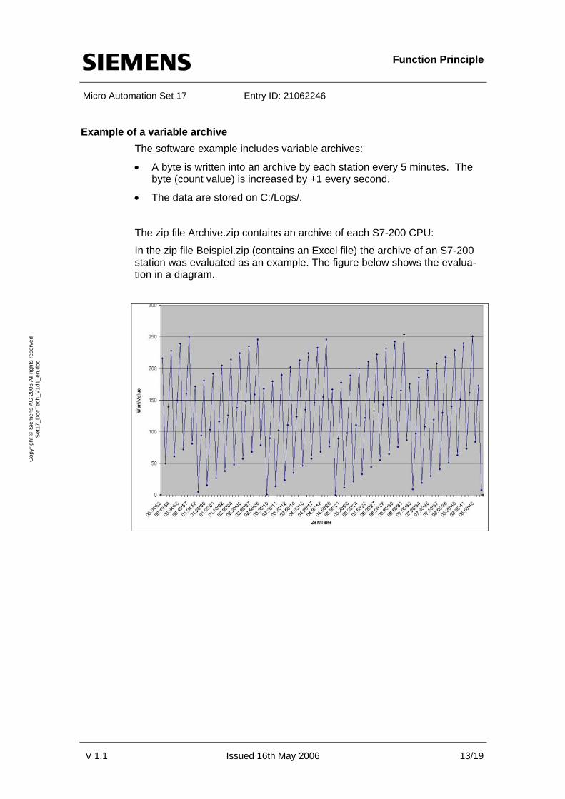
Example of a variable archive The software example includes variable archives:
• A byte is written into an archive by each station every 5 minutes. The byte (count value) is increased by +1 every second.
• The data are stored on C:/Logs/.
The zip file Archive.zip contains an archive of each S7-200 CPU:
In the zip file Beispiel.zip (contains an Excel file) the archive of an S7-200 station was evaluated as an example. The figure below shows the evalua-tion in a diagram.
V 1.1 Issued 16th May 2006 13/19
Cop
yrig
ht ©
Sie
men
s A
G 2
006
All
right
s re
serv
ed
Set
17_D
ocTe
ch_V
1d1_
en.d
oc

Configuring the Startup Software
Micro Automation Set 17 Entry ID: 21062246
V 1.1 Issued 16th May 2006 14/19
Cop
yrig
ht ©
Sie
men
s A
G 2
006
All
right
s re
serv
ed
Set
17_D
ocTe
ch_V
1d1_
en.d
oc
5 Configuring the Startup Software
Preliminary remark For the startup we offer you software examples with test code and test pa-rameters as download. The software examples support you during the first steps and tests with your Micro Automation Sets. They enable quick testing of hardware and software interfaces between the products described in the Micro Automation Sets.
The software examples are always assigned to the components used in the set and show their basic interaction. However, they are not real applications in the sense of technological problem solving with definable properties.
Download of the startup code The software example is available on the HTML page from which you downloaded this document.
The download is a ZIP file which can be unzipped with any unzip program. The zip.-file contains the following files: Table 5-1
File name Content
Set17_S7-200_V1d1_en.mwp S7-200: Program code2
Set17_HMI_CentralStati-on_RT_V1d0_en.zip
PC: Runtime, WinCC flexible RT
Set17_HMI_CentralStation_ES_V1d0_en.zip
PC: Configuration, WinCC flexible Advanced
Set17_Archive_V1d1_en.zip PC: Archive per S7-200 station
2 Click the file when working with “STEP 7 Micro/WIN 32 V3.2 SP4” or later.
Live Demo
Micro Automation Set 17 Entry ID: 21062246
6 Live Demo
6.1 Operation
The set is configured and programmed with the files of the software exam-ple (see Download).
Note A connection speed of 19200bit/s was used for the software example. All following parameters described here refer to this speed.
Adapting the software example
V 1.1 Issued 16th May 2006 15/19
Cop
yrig
ht ©
Sie
men
s A
G 2
006
All
right
s re
serv
ed
Set
17_D
ocTe
ch_V
1d1_
en.d
oc
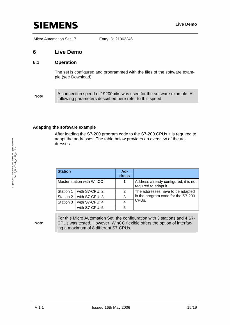
After loading the S7-200 program code to the S7-200 CPUs it is required to adapt the addresses. The table below provides an overview of the ad-dresses.
Station Ad-
dress
Master station with WinCC 1 Address already configured, it is not required to adapt it.
Station 1 with S7-CPU: 2 2 Station 2 with S7-CPU: 3 3
with S7-CPU: 4 4 Station 3
with S7-CPU: 5 5
The addresses have to be adapted in the program code for the S7-200 CPUs.
For this Micro Automation Set, the configuration with 3 stations and 4 S7-Note CPUs was tested. However, WinCC flexible offers the option of interfac-
ing a maximum of 8 different S7-CPUs.

Live Demo
Micro Automation Set 17 Entry ID: 21062246
Parameters for the MD2 dedicated line modem It is required to parameterize the following switch positions for MD2. Up (SW1 and SW2)
SW1 SW2 Switch 1 2 3 4 5 1 2 3 4 5 6 7 8 9 10 ON/OFF 0 1 0 1 1 0 0 1 1 0 0 0 0 0 0
V 1.1 Issued 16th May 2006 16/19
Cop
yrig
ht ©
Sie
men
s A
G 2
006
All
right
s re
serv
ed
Set
17_D
ocTe
ch_V
1d1_
en.d
oc
Down (SW3)
SW3 to end position (beginning/end) SW3 to tapping point (center) Switch 1 2 3 4 1 2 3 4 ON/OFF 0 1 0 1 0 1 0 0
Down (SW4)
Switch 1 2 3 4 ON/OFF 0 0 0 0
SW1 SW2
SW3 SW4

Live Demo
Micro Automation Set 17 Entry ID: 21062246 Parameterization of LTOPs (DIP switch)
The LTOPs are equipped with DIP switches 1 and 2 for parameterization. Set the switch as described in the following table.
V 1.1 Issued 16th May 2006 17/19
Cop
yrig
ht ©
Sie
men
s A
G 2
006
All
right
s re
serv
ed
Set
17_D
ocTe
ch_V
1d1_
en.d
oc
Location Left switch Right switch Beginning, LTOP1 Position 1 - Center, LTOP2 Position 1 Position 2 End LTOP1 Position 1 -
Example for determining the position
Parameterization of terminating resistors on the Profibus cable At the beginning and at the end "On"; if further stations are located in the center, the terminating resistor of these stations may not be switched on.
Setting PC interface for the communication of WinCC flexible (S7 online) WinCC flexible RT uses the access path listed under S7ONLINE via "Set PG/PC Interface". Set the access path “CP5611, MPI, 19200Bit/s”.

Live Demo
Micro Automation Set 17 Entry ID: 21062246 STEP 7-Micro/WIN settings for communication via the existing network, PC inter-face (remote maintenance)
If you want to access an S7-CPU with STEP 7-Micro/WIN using the modem you have to set the access path. Proceed as described in the graphic be-low.
V 1.1 Issued 16th May 2006 18/19
Cop
yrig
ht ©
Sie
men
s A
G 2
006
All
right
s re
serv
ed
Set
17_D
ocTe
ch_V
1d1_
en.d
oc
To enable communication, the used PG/PC must feature an MPI-Note compatible interface.
The Runtime of WinCC flexible has to be terminated to ensure that the access path is free for STEP 7-Micro/WIN.

Basic Performance Data
Micro Automation Set 17 Entry ID: 21062246
V 1.1 Issued 16th May 2006 19/19
Cop
yrig
ht ©
Sie
men
s A
G 2
006
All
right
s re
serv
ed
Set
17_D
ocTe
ch_V
1d1_
en.d
oc
7 Basic Performance Data
LOGO! Power 24V 1.3A Parameter Number/Size/Range Remarks Supply Voltage AC 100-240V Output voltage DC 24V Output current 1.3A Dimensions (W x H x D) in mm 54 (3 width modules) x 90 x 55
SIMATIC CPU S7-222 Parameter Number/Size/Range Remarks Supply voltage DC 20.4 to 28.8 V or AC 85 to 264 V Output current expansion module
340 mA
Interfaces RS 485, communication interface, expansion bus for modules
Protection system IP 20 in acc. w. IEC 529
MD2 dedicated line modem Parameter Number/Size/Range Remarks Power supply Nominal value: 24 V DC permissible range: 18 .. 32 V Current consumption of type 100 mA
Max. cable length approx. 10 km at 19,200 bps via cable type 2 x 2 x 0.8 J-Y(St)Y, into network with 2 modems MD2
Housing dimensions (H x W x D) 125 x 80 x 120 in mm
WinCC flexible advanced RT Parameter Number/Size/Range Remarks Operating system MS Windows 2000 / XP Professional
Variables Depending on order, maximum of 2000 variables with external connec-tion to the controller, internal values unlimited
Number of connectable partners, max. Depending on scale of configuration (communication), up to 8 connec-tions possible with WinCC flexible Runtime
Online languages, max. 16 Offline languages, max. 32