micro 850
TRANSCRIPT

Micro 850:Modbusto PF4M Kinetix 3 y PVC
V 2013 1.0 Page 1 of 73
Micro 850:Modbus to PF4M
Kinetix 3 y PanelView
Component

Micro 850:Modbusto PF4M Kinetix 3 y PVC
V 2013 1.0 Page 2 of 73
INTRODUCTION TO THE M ICRO 830 AND POWERFLEX 4M _______ERROR! BOOKMARK NOT DEFINED.
BEFORE YOU BEGIN _______________________________ERROR! BOOKMARK NOT DEFINED.
SETTING UP POWERFLEX 4M _______________________________________________ 1
START PROGRAMMING ____________________________________________________ 3
COMMUNICATION SETTING FOR COMMUNICATION PORT____________________________ 41
TESTING THE MODBUS COMMUNICATION PROGRAM ______________________________ 44

Micro 850:Modbusto PF4M Kinetix 3 y PVC
V 2013 1.0 Page 3 of 73
Start Programming
This section of the lab will show you how to setup the communication setting and creating a program to communication between Micro800 controller and PowerFlex 4M drive.
Setting up communication
1.Start the Connected Component Workbench for the Start Menu: Start Programs
Rockwell Automation CCW Connected Components Workbench.
Alternatively, double click on the shortcut on the Desktop .
Micro 850:Modbusto PF4M Kinetix 3 y PVC
V 2013 1.0 Page 4 of 73
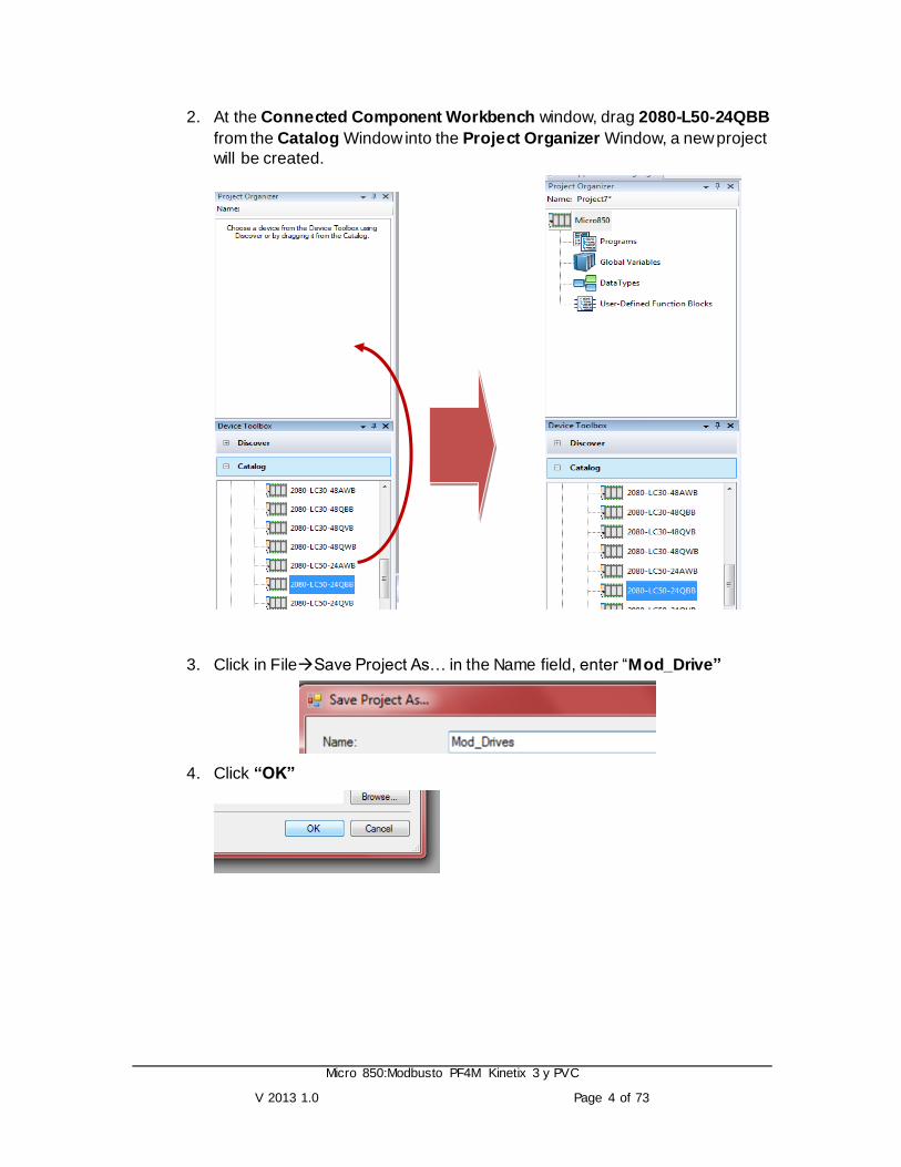
2. At the Connected Component Workbench window, drag 2080-L50-24QBB
from the Catalog Window into the Project Organizer Window, a new project
will be created.
3. Click in FileSave Project As… in the Name field, enter “Mod_Drive”
4. Click “OK”

Micro 850:Modbusto PF4M Kinetix 3 y PVC
V 2013 1.0 Page 5 of 73
5. In the Project Organizer double click in Global Variables
6. Create the following variables shown in the table below
PF_ON BOOL
PF_STOP BOOL
SERVO_ON BOOL
SERVO_OFF BOOL
START_INDEX BOOL
SET_PFSPEED BOOL
JOG_PF BOOL
JOG_ON BOOL
JOG_OFF BOOL
JOG_SERV BOOL
SET_SERVJOGS BOOL
SPEED_PFREF INT
JOG_PFSPEED INT
SET_PF_JSP BOOL
JOG_SPDSERV INT
7. The Local Variable will appear as shown upon completion.

Micro 850:Modbusto PF4M Kinetix 3 y PVC
V 2013 1.0 Page 6 of 73

Micro 850:Modbusto PF4M Kinetix 3 y PVC
V 2013 1.0 Page 7 of 73
Select the User Global Variables TabV
Then click OK
Then click here to
select the PF_ON variable
Enter the register address in this field.
4. Map the PF_ON variable to register address 500001

Micro 850:Modbusto PF4M Kinetix 3 y PVC
V 2013 1.0 Page 8 of 73
5. Repeat steps 3 and 4 for the others variables, and map them to the register
addresses as shown below

Micro 850:Modbusto PF4M Kinetix 3 y PVC
V 2013 1.0 Page 9 of 73

Micro 850:Modbusto PF4M Kinetix 3 y PVC
V 2013 1.0 Page 10 of 73
Create a PanelView Component Application
First you have to decide how you want to create the application, this can be as online or offline.
A. Create an Online application The first one is by Ethernet. First of all energize your PanelView to get IP address.
Set the IP Address to your personal computer
1. Click Start >> Settings>> Network Connections 2. Click Local Area Connection

Micro 850:Modbusto PF4M Kinetix 3 y PVC
V 2013 1.0 Page 11 of 73
Configure Browser Settings
3. Click Properties 4. Double Click Internet Protocol (TCP/IP) 5. Mark Use the following IP address, and in IP
address put your IP. Note: Remember the last number of IP address
should be different from IP of the PanelView. 6. Click Ok
Note : There are different ways to change the computer IP,
verify the way, and change the IP.

Micro 850:Modbusto PF4M Kinetix 3 y PVC
V 2013 1.0 Page 12 of 73
Launch PanelView Explorer
(Internet Explorer 7 web browser, Mozilla Firefox 2.0 or 3.0 Web Browser)

Micro 850:Modbusto PF4M Kinetix 3 y PVC
V 2013 1.0 Page 13 of 73
B. Create an Offline application
4. Follow the next section “Create a PanelView application”.
Then click here to select the PF_ON
variable

Micro 850:Modbusto PF4M Kinetix 3 y PVC
V 2013 1.0 Page 14 of 73
5. Once you create your application you need to transfer the Offline PVc Application to a PVc Terminal.

Micro 850:Modbusto PF4M Kinetix 3 y PVC
V 2013 1.0 Page 15 of 73

Micro 850:Modbusto PF4M Kinetix 3 y PVC
V 2013 1.0 Page 16 of 73

Micro 850:Modbusto PF4M Kinetix 3 y PVC
V 2013 1.0 Page 17 of 73
Micro 850:Modbusto PF4M Kinetix 3 y PVC
V 2013 1.0 Page 18 of 73
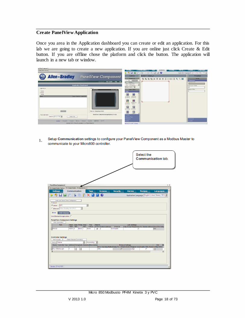
Create PanelView Application Once you area in the Application dashboard you can create or edit an application. For this
lab we are going to create a new application. If you are online just click Create & Edit button. If you are offline chose the platform and click the button. The application will launch in a new tab or window.
1.

Micro 850:Modbusto PF4M Kinetix 3 y PVC
V 2013 1.0 Page 19 of 73

Micro 850:Modbusto PF4M Kinetix 3 y PVC
V 2013 1.0 Page 20 of 73
2.
3.
4.
Click the HIM Tags tab
Click add

Micro 850:Modbusto PF4M Kinetix 3 y PVC
V 2013 1.0 Page 21 of 73
Click on HMI Screens….
Create a maintained pushbutton linked to tag PF_ON .
Create the following tags as shown below-make sure to choose th correct data type
Create a screen display with objects linked to the tags you just created

Micro 850:Modbusto PF4M Kinetix 3 y PVC
V 2013 1.0 Page 22 of 73
Repeat these steps to create the following screen
Configure the Connections
Write Tag and Indicator Tag to PF_ON tag

Micro 850:Modbusto PF4M Kinetix 3 y PVC
V 2013 1.0 Page 23 of 73
1 PF_ON
2 PF_STOP
3 SERVO_ON
4 SERVO_OFF
5 START_INDEX
6 SET_PFSPEED
7 JOG_PF
8 JOG_ON
9 JOG_OFF
10 JOG_SERV
11 SET_SERVJOGS
12 SET_PF_JSP
1 2
7
4 3
5 6
8 9
10
11
12
Create a numeric input Enable object linked to tag, SPEED_PFREF
Drag and drop a numeric
entry object from the entry
object palette onto your display

Micro 850:Modbusto PF4M Kinetix 3 y PVC
V 2013 1.0 Page 24 of 73
Repeat these steps to create the following screen
1 SPEED_PFREF 2 JOG_PFSPEED
3 JOG_SPDSERV
In the Numeric Entry
Properties panel, select
the connections tab and configure the write tag
and indicator tag to,
SPEED_PFREF
1
2
3

Micro 850:Modbusto PF4M Kinetix 3 y PVC
V 2013 1.0 Page 25 of 73
5. Create a Goto config button and a text as show next
6. If you are online you need to validate your application. Click Validate Application.
Wait for the next prompt. If there are any warnings the application is valid, but no with errors.
Save your work, and close the application with the next icon.

Micro 850:Modbusto PF4M Kinetix 3 y PVC
V 2013 1.0 Page 26 of 73
Setting Up PowerFlex 4M
Configuring the PowerFlex 4M
In this section of the lab, the PowerFlex 4M drive will be configured to communicate with the Micro830 controller.
The following is the overview of the steps to be taken for configuring the drive.
Reset the Drive to Factory Default
Setting up the control and the speed referencing of the Drive.
Setting up the communication setting and the Node number of the Drive.
To complete this lab, the drive needs to be reset to the factory defaults. Follow these steps:
Using the keypad
1. To verify if the drive is controlled by the integral keypad, check if the Green LED
beside the green start button is lit. If the LED is on, the drive can be control led by
pressing the Start/Stop button in the keypad. To control the speed, turn the
potentiometer above the Green Led.
Key Name Description
Esc Escape Back up one step in programming menu/ Cancel a change to a parameter value / Exit Program Mode.
Sel Select Advance one step in the programming menu / Select a digit when viewing parameter value.
Up Arrow, Down Arrow
Scroll through groups and parameters/ Increase/decrease the value of a flashing digit.

Micro 850:Modbusto PF4M Kinetix 3 y PVC
V 2013 1.0 Page 27 of 73
2. Get familiar with the integral keypad:
Resetting to factory defaults (Setting Parameter P112 to a value of 1)
3. Press the Esc key (multiple times if necessary) until the display shows “0.0”
4. Press the Enter key once and the display should show “xyyy” where x is d,P,t,C
or A and y is a numerical value.
5. Verify that the leftmost alphabet character (x) is flashing.
6. Press the Up Arrow or Down Arrow key until the leftmost character displayed is
a flashing “P”. Press the Enter key and the “P” will stop flashing and the
rightmost numeric character is flashing.
7. Press the Up Arrow or Down Arrow key until “P112” is displayed.
8. Press the Enter key and a “0” will be displayed as the current value of parameter
P112.
9. Press the Enter key again and “0” begins flashing. Press the Up Arrow key to
adjust the value to “1” and press the Enter key to enable the default settings.
10. The display will flash “F048” and the red FAULT LED will flash also. This fault
indicates that the drive parameters have been reset to factory default. Press the
Red Stop Button to clear the fault.
11. Since both green LEDs on the front of the drive are on, verify that you can:
Start the drive by pushing the Green Start Button (if the drive doesn‟t start and the
display still reads “0.0”, try rotating the speed potentiometer clockwise).
Then verify that you can stop the drive by pushing the Red Stop Button (note that
the drive does not stop immediately, but decelerates at a configured rate to zero).
Start the drive again and verify that once the drive is done accelerating, the speed
potentiometer can be used to speed up or slow down the drive.
Now stop the drive by pressing the Red Stop Button.
Enter Advance one step in programming menu/ Save a change to a parameter value.

Micro 850:Modbusto PF4M Kinetix 3 y PVC
V 2013 1.0 Page 28 of 73
Changing the Control and Speed References
This lab shows communications between the Micro 830 and the PF4M drive. The drive needs to be set to accept remote control commands from the Micro 830. This is done by setting the parameters for the Start Source (P106) and Speed reference (P108) to a value of “5”.
Setting the start source to “Remote”. (Comm port) - P106
12. Press the Esc key (multiple times if necessary) until the display shows “0.0”.
13. Press the Enter key once, the display show “xyyy” where x is and alphabet
(d,P,t,C or A) and y is numerical number.
14. Press the Up Arrow or Down Arrow key until the leftmost alphapet value
displayed is a flashing “P”. Press the Enter key. Now the “P” stops flashing and
the rightmost numeric character is flashing.
15. Press the Up Arrow or Down Arrow key until “P106” is displayed.
16. Press the Enter key and the current value of parameter P106 will be displayed,
which by default is “0”.
17. Press the Enter key again and “0” begins flashing. Press the Up Arrow key
multiple times to adjust the value to “5” and then press the Enter key to accept
this value. (“5” should not be flashing any longer) Notice that the green LED next
to the green Start button on the drive is now off.
18. Press the Esc key and “P106” should be displayed (with the “6” flashing). Press
the Up Arrow key twice so that “P108” is displayed (with the “8” flashing).
Setting the Speed Reference to “Remote” (Comm port) - P108
19. Press the Enter key and the current value of parameter P108 will be displayed.
The value of “0” means “Keypad”.
20. Press the Enter key again and “0” begins flashing. Press the Up Arrow key
multiple times to adjust the value to “5” and then press the Enter key to accept
this value. (“5” should not be flashing any longer) Notice that the green LED next
to the Speed Potentiometer on the drive is now off.
21. Press the Esc key multiple times until “0.0” is displayed. The drive is now ready
to be controlled by Modbus RTU communication commands initiated from the
Micro 830 controller.

Micro 850:Modbusto PF4M Kinetix 3 y PVC
V 2013 1.0 Page 29 of 73
Changing the communication settings of the drive
The following steps will show how to change the communication setting of the PowerFlex 4M Drives for communication with Micro 830 via Modbus RTU communication.
Modbus Communication Settings:
Parameter Description Setting
C302 Comm. Data Rate (Baud Rate) 4 = 19200 bps 4
C303 Comm. Node Addr. 2
C304 Comm. Loss Action ( Action taken when loss communication) 0 = Fault with coast stop
0
C305 Comm. Loss Time (Time remain in communication before taking action set in C304) 5 sec ( Max. 60)
5
C306 Comm. Format (Data/Parity/Stop) RTU:8 Data Bit, Parity None, 1 Stop bit
0
Setting the Baud Rate – C302
22. Press the Esc key (multiple times if necessary) until the display shows “0.0”.
23. Press the Enter key once, the display shows “xyyy” where x is and alphabet
(d,P,t,C or A) and y is numerical number.
24. Press the Up Arrow or Down Arrow key until the leftmost alphanumeric value
displayed is a flashing “C”. Press the Enter key. Now the “C” stops flashing and
the rightmost numeric character is flashing.
25. Press the Up Arrow or Down Arrow key until “C302” is displayed.
26. Press the Enter key and the current value of parameter C302 will be displayed,
which by default is “3”.
27. Press the Enter key again and “3” begins flashing. Press the Up Arrow key to
change the baud rate of the drive to 19200 bps to “4” and then press the Enter
key to accept this value.
28. Press the Esc key and “C302” should be displayed (with the “2” flashing). Press
the Up Arrow once so that “C303” is displayed (with the “3” flashing).
Setting the Node Address – C303
29. Press the Enter key and the current value of parameter C303 will be displayed,
which by default is “100”.

Micro 850:Modbusto PF4M Kinetix 3 y PVC
V 2013 1.0 Page 30 of 73
30. Press the Enter key again and “100” begins flashing. Press the Down Arrow key
to adjust the Modbus node address to “2” (for multiple drives, you would assign
address 2 for the second drive, 3 for the third drive, etc.) and then press the
Enter key to accept this value.
31. Press the Esc key and “C303” should be displayed (with the “3” flashing).
Verify Communications Loss Action – C304, Communications Loss Time –C305, Communications Format –C306
32. Parameter C304, C305 and C306 should be the factory default value, which is
“0”, “5” and “0” respectively. Verify if C304 value is “0” by pressing the Enter key
and the current value of parameter C304 will be displayed, which by default is
“0”.
33. Press the Esc key again and “C304” should be displayed (with the “4” flashing).
Press the Up Arrow once so that “C305” is displayed (with the “5” flashing).
34. Press Enter key and the current value of parameter C305 will be displayed,
which by default is “5”.
35. Press the Esc key again and “C305” should be displayed (with the “5” flashing).
Press the Up Arrow once so that “C306” is displayed (with the “6” flashing).
36. Press Enter key and the current value of parameter C306 will be displayed,
which by default is “0”.
37. Press the Esc key (multiple times if necessary) until the display shows “0.0”.
8. Turn off the power to the drive until the PowerFlex 4M display blanks out
completely, then restore power to the PowerFlex 4M. The drive is now ready
to be controlled by Modbus RTU communication commands initiated from the
Micro 830 controller.
9.
10. Under the Project Organizer, right click on the Programs select Add and
select New LD: Ladder Diagram.

Micro 850:Modbusto PF4M Kinetix 3 y PVC
V 2013 1.0 Page 31 of 73
43. Right click on UntitledLD and select Rename.
44. Type in “Mod_Message” and press Enter:

Micro 850:Modbusto PF4M Kinetix 3 y PVC
V 2013 1.0 Page 32 of 73
11. Double click on Mod_Message. From the Toolbox ,drag a Block to the rung

Micro 850:Modbusto PF4M Kinetix 3 y PVC
V 2013 1.0 Page 33 of 73
Creating a Time On-Off (TONOFF) Block
12. From the Instruction Block Selector Window, select TONOFF.
13. Click OK to proceed.

Micro 850:Modbusto PF4M Kinetix 3 y PVC
V 2013 1.0 Page 34 of 73
14. Click on variable, and enter in T#2S for both PT and PTOFF
15. From the Toolbox, drag a Reverse Contact to the Rung 1, before the
TONOFF_1.
16. From the Variable Selector Window, select TONOFF_1.Q.

Micro 850:Modbusto PF4M Kinetix 3 y PVC
V 2013 1.0 Page 35 of 73
17. The Rung 1 will look like the following:
18. From the Toolbox, create a new rung in the workspace.

Micro 850:Modbusto PF4M Kinetix 3 y PVC
V 2013 1.0 Page 36 of 73
19. Drag a Direct Contact to the Rung 2.
20. From the Variable Selector Window, select TONOFF_1.Q.
21. From the Toolbox, drag a Block to Rung 2.

Micro 850:Modbusto PF4M Kinetix 3 y PVC
V 2013 1.0 Page 37 of 73
22. From the Instruction Block Selector window, select MSG_MODBUS
23. Then click on OK to proceed.
24. Double click on the Local Variable at the Project Organizer.

Micro 850:Modbusto PF4M Kinetix 3 y PVC
V 2013 1.0 Page 38 of 73
Creating Variables
25. Create the following variables shown in the table below in the Mod_Message-
VAR Tab.
Variable Name Data Type
1. Cancel BOOL
2. D2_lcfg MODBUSLOCPARA
3. D2_Tcfg MODBUSTARPARA
4. D2_laddr MODBUSLOCADDR
5. D2_error BOOL
6. D2_errorc UINT
26. The Local Variable will appear as shown upon completion.
27. Double click on the Mod_Message, assign the variable to the parameters of
the MSG_MODBUS_1.

Micro 850:Modbusto PF4M Kinetix 3 y PVC
V 2013 1.0 Page 39 of 73
Variable Name Parameter of MSG_MODBUS_1
1 Cancel Cancel
2 D2_lcfg LocalCfg
3 D2_Tcfg TargetCfg
4 D2_laddr LocalAddr
5 D2_error Error
6 D2_errorc Error ID
Upon completion, the Rung 2 will appear as followed:
Micro 850:Modbusto PF4M Kinetix 3 y PVC
V 2013 1.0 Page 40 of 73
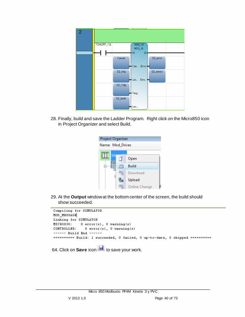
28. Finally, build and save the Ladder Program. Right click on the Micro850 icon
in Project Organizer and select Build.
29. At the Output window at the bottom center of the screen, the build should
show succeeded.
64. Click on Save icon to save your work.

Micro 850:Modbusto PF4M Kinetix 3 y PVC
V 2013 1.0 Page 41 of 73
Communication Setting for Communication Port
This section of the lab will show you how to add a Serial Communication Plug-In module and configure the Serial Plug-In for Modbus Communication.
65. Double on Micro850 under the Project Organizer. The following Micro850 tab
will appear.
66. Right-Click on the first <Empty>in the list, and select 2080-SERIALISOL.

Micro 850:Modbusto PF4M Kinetix 3 y PVC
V 2013 1.0 Page 42 of 73
Upon selection, the image of the Serial Communication Plug-in module will appear.
67. At the Properties, select the following settings.
Note: The Baud Rate for the PowerFlex 4M and Micro 830 Controller be the same .

Micro 850:Modbusto PF4M Kinetix 3 y PVC
V 2013 1.0 Page 43 of 73
68. At the Advanced Settings, select RS485 in the Media Field.
69. Build the program again. Right click on the Micro830 icon in Project Organizer
and select Build.
70. At the Output window at the bottom center of the screen, the build should show
succeeded.
71. Click on Save icon to save your work.
Micro 850:Modbusto PF4M Kinetix 3 y PVC
V 2013 1.0 Page 44 of 73
Testing the Modbus Communication Program
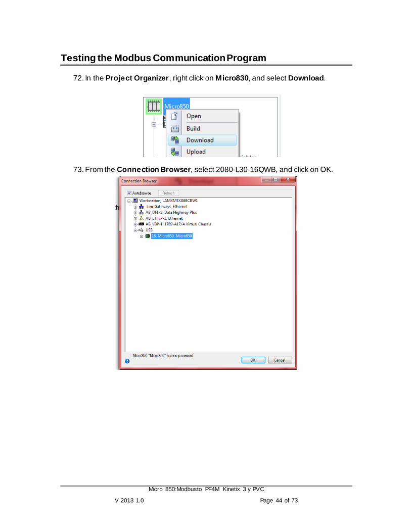
72. In the Project Organizer, right click on Micro830, and select Download.
73. From the Connection Browser, select 2080-L30-16QWB, and click on OK.

Micro 850:Modbusto PF4M Kinetix 3 y PVC
V 2013 1.0 Page 45 of 73
74. The following dialog box will appear for confirmation of the downloading if the controller is in RUN mode. Click on Yes to proceed.
In the completion of downloading the program, the Output window will display Succeeded
75. The following window will appear to change from Program Mode to Run Mode. Click on Yes to proceed.

Micro 850:Modbusto PF4M Kinetix 3 y PVC
V 2013 1.0 Page 46 of 73
76. Click on the at the Debug Toolbar, the programming workspace will change from white background to beige background.
At the same time, the status and value of the parameters will be display on the screen.

Micro 850:Modbusto PF4M Kinetix 3 y PVC
V 2013 1.0 Page 47 of 73
77. To test the Modbus Communication, assign the following value to the variables:
Variable Name Description Value
D2_Icfg.Channel Serial Port Channel no. for communication 2, 5 or 6 depending on application.
5
D2_Icfg. TriggerType
0: for one shot, 1: for continuous trigger
( 1 continuous Trigger - Function not available yet)
0
D2_lcfg.Cmd Modbus Communication Function Code
03(Read Single Coil), 06 (Write Single Coil) or 16 (Write Multiple Coil)
6
D2_Icfg.ElementCnt No of data to Read or Write 1
D2_Tcfg.Addr Register Address of the Slave to Read or Write
8193
D2_Tcfg.Node Slave Node Number 2
D2_laddr[1] Data to Write / Return data from Slave if read command is issued. ( Bit 2 of 8193 = Start)
2
78. Change the D2_lcfg. Channel, double click on the variable,

Micro 850:Modbusto PF4M Kinetix 3 y PVC
V 2013 1.0 Page 48 of 73
The following Variable Monitoring window will appear.
79. Click on to expandable the variable‟s tree.
80. To change the value of the D2_lcfg.Channel, double click on Logical Value of D2_lcfg.Channel. Change the value with respect to the table shown above, 5.

Micro 850:Modbusto PF4M Kinetix 3 y PVC
V 2013 1.0 Page 49 of 73
Note: The Channel number is determine by the serial port used for communication.
The following is the port number assignment.
81. Repeat Steps 10 till all the respective variables‟ values had been changed.
When the last parameter D2_laddr.[1], is enter, the RUN Led on the PowerFlex 4M will turn ON. This indicated that a Start Command was send to the Drive.
82. Change the respective value of the following variables to as shown.
Variable Name
Description Value
D2_Tcfg.Addr Register Address of the Slave to Read or Write
8194
D2_laddr[1] Data to Write / Return data from Slave if read command is issued. ( Bit 1 of 8193 = Start)
200
Notice that the Display on the PowerFlex 4M will show 20.0 (200 x 0.1), and the motor will start running.
Note: Address 8194 is the Speed Reference address for the PowerFlex 4M. To vary the speed of the drive, change the value writing to 8194. Please note a multiplier of 0.1 will be applied.
Channel 2
Channel 4
Channel 5 Channel 6

Micro 850:Modbusto PF4M Kinetix 3 y PVC
V 2013 1.0 Page 50 of 73
83. Change the value of the following variables as shown:
Variable Name
Description Value
D2_Tcfg.Addr Register Address of the Slave to Read or Write
8193
D2_laddr[1] Data to Write / Return data from Slave if read command is issued. ( Bit 2 of 8193 = Start)
1
Notice that the Display on the PowerFlex 4M will ramp down till 0.0 and the motor will stop running.
Note: Address 8193 is the control register, where Bit 0 of 8193 is Stop, and Bit 1 of 8193 is Start.
84. To stop the monitor of the variable, click on at the Debug Toolbar.
Configuring the Kinetix 3 Drive (20 Minutes) We will first be putting the Kinetix 3 servo drive into a known state and then configuring it for our needs. The drive may be setup for operation in a mode other than indexing, plus the communication protocol may not work for our immediate needs.
Configure the Drive Communication Settings for Serial
We will be connecting to our Kinetix 3 drive using a serial connection. The PC at your workstation has a 9-pin serial port on the back of the processor unit, but an extension has been brought up to your tabletop for easy access.
1. Follow the steps in the Before You Begin section of this document before proceeding.
2. Connect the drive demo to 120Vac using the attached power cord.
3. Turn power switch ON (position „1‟) located in the lower right corner of the demo unit.

Micro 850:Modbusto PF4M Kinetix 3 y PVC
V 2013 1.0 Page 51 of 73
4. Disconnect any communication cables from the Up Port and the Down Port of the Kinetix 3 drive.
5. Press and release the Mode/Set key until the message Pr-0.00 is displayed.
This is the Parameter Edit mode for changing drive parameters.
TIP: Other modes available include Index Edit mode for changing the indexing profile values and Display mode for observing operating values of the drive and motor.
6. Use the Up button to change the display to Pr-0.09 and press the Enter key.
Pr-0.09 is the communication protocol setting for the serial port on the Kinetix 3 drive. It will have (2) unique settings for our usage in the lab:
Pr-0.09 = 0005 for communicating with a PC using Ultraware (serial ASCII)
Pr-0.09 = 1102 for communicating with the Micro830 using Modbus RTU

Micro 850:Modbusto PF4M Kinetix 3 y PVC
V 2013 1.0 Page 52 of 73
7. Use the Left/Right and Up/Down arrows on the keypad to change Pr-0.09 to ‘0005’ for use with Ultraware.
The drive was likely left in the Modbus mode from the previous user. Ultraware will not communicate in the Modbus mode.
8. PRESS and HOLD the Mode/Set key until the display flashes.
The drive is now configured for use with Ultraware.
Micro 850:Modbusto PF4M Kinetix 3 y PVC
V 2013 1.0 Page 53 of 73
Connect to the Drive using Ultraware
The following drive parameters will be configured using Ultraware software:
Operation mode
Modbus control function parameters
Digital inputs
Digital outputs
Indexing parameters
Homing parameters
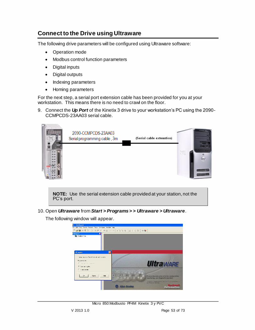
For the next step, a serial port extension cable has been provided for you at your workstation. This means there is no need to crawl on the floor.
9. Connect the Up Port of the Kinetix 3 drive to your workstation‟s PC using the 2090-CCMPCDS-23AA03 serial cable.
NOTE: Use the serial extension cable provided at your station, not the PC‟s port.
10. Open Ultraware from Start > Programs > > Ultraware > Ultraware.
The following window will appear.

Micro 850:Modbusto PF4M Kinetix 3 y PVC
V 2013 1.0 Page 54 of 73
11. At the Ultraware Dialog box, select Create new file.
12. You may be prompted with a Tip of the Day. Simply answer OK to the prompt.
The software will then attempt to scan the network for connected servo drive.
The scan will fail after not finding any drives. Your default serial settings will likely not match those required by the Kinetix 3 drive.
13. From the drop-down menu, select Tools > Serial Port.

Micro 850:Modbusto PF4M Kinetix 3 y PVC
V 2013 1.0 Page 55 of 73
14. Change your Baud Rate to 57600 as shown and press OK.
15. Check for drives again by selecting Tools > Rescan from the menu.
16. When a node is scanned, the following dialog box will appear. Click on No to continue.
NOTE: This wizard currently assists users with stepper and analog operations. However, we will be using the Indexing operation mode.
This may be COM2 when
using VMware.

Micro 850:Modbusto PF4M Kinetix 3 y PVC
V 2013 1.0 Page 56 of 73
17. Double click on the Drive under On-Line Drives in the workspace on the left (the actual name may differ).
The parameter summary screen will be shown on the right.

Micro 850:Modbusto PF4M Kinetix 3 y PVC
V 2013 1.0 Page 57 of 73
Configure the Drive Using Ultraware
It‟s always a great idea to put the drive into a known state. Who knows what settings exist?
18. Press Reset to Factory Settings on the right.
This will eliminate a lot of little issues along the way.
19. Confirm any prompts to complete the reset process.
The motor used in the demo has a smart encoder that allows the drive to identify it automatically. That‟s one less step we have to consider within the lab.
20. Select Operation Modes from the pull-down menu, select the Indexing/None. Answer Yes to confirm the reset.
This is to configure the Kinetix 3 as a stand-alone indexing drive.
21. Expand the Communications branch.

Micro 850:Modbusto PF4M Kinetix 3 y PVC
V 2013 1.0 Page 58 of 73
22. Configure the following Modbus function control settings:
These settings will allow us to update parameters from the controller over Modbus but issue commands from the drive I/O.
We would have to create a Modbus message for enable/disable, start index, stop index and fault reset if we changed the Input Function Control to Enable. We simply don‟t have time in the lab to create all of these messages.
NOTE: We will eventually change these settings to Modbus Protocol as well, but changing them now would knock us offline with Ultraware.
23. Expand the Drive tree and select Digital Inputs by double clicking.
24. Assign Input 1 as the Drive Enable input. Selection can be made from the pull down menu.

Micro 850:Modbusto PF4M Kinetix 3 y PVC
V 2013 1.0 Page 59 of 73
Assign the remaining inputs according to the table shown below.
Parameter Value
Input 1 Drive Enable
Input 2 Start Indexing
Input 3 Stop Indexing
Input 4 Start Homing
Input 5 Fault Reset
Upon completion, the Digital Input parameter should look like the following.
25. From the Drive tree, select the Digital Outputs.
26. Assign Output 1 as Ready. Selection can be made from the pull down menu.

Micro 850:Modbusto PF4M Kinetix 3 y PVC
V 2013 1.0 Page 60 of 73
Assign the remaining outputs according to the table shown below.
Parameter Value
Output 1 Ready
Output 2 Axis Homed
Output 3 Brake
Upon completion, the Digital Output Parameter should look as followed.
Note that none of the outputs should be on currently on the demo unit.

Micro 850:Modbusto PF4M Kinetix 3 y PVC
V 2013 1.0 Page 61 of 73
Configure with Required Indexing Moves
27. Expand the Mode Configuration branch and double click on the Indexing icon from the workspace.
The index table will be shown on the right.
The servo motor used in this demo unit includes an encoder that produces 131,072 counts per motor rev. We will make each index move a factor of this.
28. Expand Index 0 Setup and configure the index as follows:
This means 1 motor rev in the forward direction.
29. Then expand and configure Index 1 Setup as follows:
When the Start Index input is activated, Index 0 will execute. Upon completion, Index 1 will execute immediately before coming to a stop.
1 rev forward
1 more rev forward

Micro 850:Modbusto PF4M Kinetix 3 y PVC
V 2013 1.0 Page 62 of 73
30. Proceed to configure Index 2 Setup as shown.
Although we won‟t be testing this particular move (Index 2) in the next section, you will have the opportunity to use it in Extra Task if time permits. Stay tuned.
TIP: The drive also allows the user to use custom positioning and velocity units, which only appear in Ultraware software. The commands from any external controllers over Modbus would still use encoder counts and motor RPM.
31. Click on Save to save the parameters upon completion. Answer Yes to upload a copy of the drive‟s parameters.
Select a location (like My Documents) and give the file a name in order to complete the process.
2 revs backwards

Micro 850:Modbusto PF4M Kinetix 3 y PVC
V 2013 1.0 Page 63 of 73
Configure the Required Homing Procedure
32. From Drive > Mode Configuration, select Homing.
33. Configure the Homing Type as Home to Marker by selecting from the pull down menu.
34. Configure the rest of the parameters as shown:
35. On a topic related to homing, move to the Encoders branch and set the Encoder Backup Battery setting to Not Installed. Our demo units do not have batteries and will cause an error.

Micro 850:Modbusto PF4M Kinetix 3 y PVC
V 2013 1.0 Page 64 of 73
Configure the Drive Communication Settings for Modbus
Now we‟ll need to set the drive to the Modbus RTU protocol for it to receive commands from the Micro830 controller.
36. You may close Ultraware software at this point.
37. Turn the DRIVE ENABLE to the off (left) position to disable the drive.
38. Disconnect any communication cables from the Up Port and the Down Port of the Kinetix 3 drive.
TIP: Ignore the E.030 fault (it is caused by our modified demo units).
39. Press and release the Mode/Set key until the message Pr-0.00 is displayed.
40. Use the Up button to change the display to Pr-0.09 and press the Enter key.

Micro 850:Modbusto PF4M Kinetix 3 y PVC
V 2013 1.0 Page 65 of 73
Recall the following table:
41. Use the Left/Right and Up/Down arrows on the keypad to change Pr-0.09 to ‘1102’ for use with Ultraware.
42. PRESS and HOLD the Mode/Set key until the display flashes.
43. Connect the 2090-CCMCNDS-48AAxx cable between the Up Port on the Kinetix 3 and the 8-pin mini-DIN connector on the Micro830 controller. This is the serial Modbus communication cable. See your instructor if you cannot find the cable.

Micro 850:Modbusto PF4M Kinetix 3 y PVC
V 2013 1.0 Page 66 of 73
The drive is now ready for use with the Micro850 controller.
To test the Modbus Communication and write your new speed value, we will assign the following values on rung 1 to the variables. The steps that follow will guide you through this task.

Micro 850:Modbusto PF4M Kinetix 3 y PVC
V 2013 1.0 Page 67 of 73
Variable Name Description Value
SPEED_Lcfg.Channel Serial port channel number for the physical communication port you have chosen (see figure below):
- 2 for the embedded serial port
- 5 for the plug-in serial module if in slot 1
- 6 for the plug-in serial module if in slot 2
2
SPEED_Lcfg. TriggerType 0: for one shot, 1: for continuous trigger
0
SPEED_Lcfg.Cmd Modbus Communication Function Code
03 (Read Single), 06 (Write Single) or 16 (Write Multiple)
6
SPEED_Lcfg.ElementCnt No. of data words to Read or Write 1
SPEED_Tcfg.Addr Register Address of the Slave to Read or Write
6601
SPEED_Tcfg.Node Slave Node Number 1
SPEED_Laddr[1] Data to Write/ Return data from Slave if read command is issued. This is the new 50 RPM speed command.
50
Crear variables a enclavar
Variables on of y set
PowerFlex and PVc
1. In Local Variable tab create the next variables

Micro 850:Modbusto PF4M Kinetix 3 y PVC
V 2013 1.0 Page 68 of 73
Pay attention in the initial values
2. Create the next rung
This is for power on the PF
3. Now create this rung
This is for power off the PF
4 .Now create this
This is for set the reference speed
4. Build the program again. Right click on the Micro850 icon in Project
Organizer and select Build.

Micro 850:Modbusto PF4M Kinetix 3 y PVC
V 2013 1.0 Page 69 of 73
5. In the Project Organizer, right click on Micro850, and select Download.

Micro 850:Modbusto PF4M Kinetix 3 y PVC
V 2013 1.0 Page 70 of 73
Kinetix and PVc
1. Under the Project Organizer, right click on the Programs select Add and select
New LD: Ladder Diagram.
2. Right click on UntitledLD and select Rename.

Micro 850:Modbusto PF4M Kinetix 3 y PVC
V 2013 1.0 Page 71 of 73
3. Type in “Mod_Message_kinetix” and press Enter:
6. In Local Variable tab create the next variables
Variable Name Data Type Initial Value
1. KCancel BOOL
2. K2_lcfg MODBUSLOCPARA
3. K2_Tcfg MODBUSTARPARA
4. K2_laddr MODBUSLOCADDR
5. K2_error BOOL
6. K2_errorc UINT
7. Kofon UDINT 3001
8. Kon WORD 1
9. Koff WORD 0
10. Indxaddr UDINT 3003
11. Indx WORD 1
7. Now create the next rungs

Micro 850:Modbusto PF4M Kinetix 3 y PVC
V 2013 1.0 Page 72 of 73
8. Build the program again. Right click on the Micro850 icon in Project
Organizer and select Build.

Micro 850:Modbusto PF4M Kinetix 3 y PVC
V 2013 1.0 Page 73 of 73
9. In the Project Organizer, right click on Micro850, and select Download.