michael stuebner optimal design of composite structures
TRANSCRIPT
Structural and Multidisciplinary Optimization manuscript No.(will be inserted by the editor)
Robert Lipton · Michael Stuebner
Optimal design of composite structures for strength andstiffness: an inverse homogenization approach
Preprint: To Appear in Structural and Multidisciplinary Optimization 2007
Abstract We introduce a rigorously based numericalmethod for compliance minimization problems in thepresence of point wise stress constraints. The methodis based on new multiscale quantities that measure theamplification of the local stress due to the microstruc-ture. The design method is illustrated for two differentkinds of problems. The first identifies suitably gradeddistributions of fibers inside shaft cross sections that im-part sufficient overall stiffness while at the same timeadequately control the amplitude of the local stress ateach point. The second set of problems are carried outin the context of plane strain. Here we recover a novelclass of designs made from locally layered media for mini-mum compliance subject to point wise stress constraints.The stress constrained designs place the more compliantmaterial in the neighborhood of stress concentrators as-sociated with abrupt changes in boundary loading andreentrant corners.
Keywords Stress constraints · Optimal structuraldesign
This research is supported by NSF through grant DMS-0406374 and by the Air Force Office of Scientific Research,Air Force Materiel Command USAF, under grant numbersF49620-02-1-0041 and FA9550-05-1-0008.
R. LiptonDepartment of MathematicsLouisiana State UniversityBaton Rouge, LA 70803 Tel.: +1-225-5781569Fax: +1-225-5784276E-mail: [email protected]
M. StuebnerDepartment of MathematicsLouisiana State UniversityBaton Rouge, LA 70803Tel.: +1-225-5787989Fax: +1-225-5784276E-mail: [email protected]
1 Introduction
It is now well established that homogenization theoryis an effective tool for the design of composites for op-timal structural compliance and natural frequency seeAllaire (2002), Bendsøe and Sigmund (2003), Cherkaevand Kohn (1997), Cherkaev (2000), Lewinski and Telega(2000), Lurie (1993), Olhoff (1996), Tartar (2000). Onthe other hand relatively little work has been directed to-wards the solution of stress constrained composite designproblems. Recently new efforts have initiated the devel-opment of numerical methods for structural optimizationin the presence of stress constraints. The investigationgiven in Duysinx and Bendsøe (1998) provides a numer-ical method for the stress constrained minimum volumedesign problem. The method is carried out using an em-pirical model known as the Solid Isotropic Microstruc-ture with Penalization (SIMP) model, see Bendsøe andSigmund (2003). The problem of mean square stress con-strained structural optimization for fiber reinforced shaftsis taken up in Lipton (2002). In that work a numeri-cal algorithm is developed based on a suitable homog-enized quantity (the covariance tensor) that rigorouslyencodes the mean square stress constraints. The workof Allaire, Jouve and Mallot (2004) introduces a partialrelaxation for topology optimization for minimum meansquare stress using finite rank laminates.
The general theory behind the homogenization ap-proach to mean square stress (or gradient) constrainedstructural optimization is significantly different from thetheory of compliance minimization. It is demonstrated inLipton (2002), Lipton (2004) that the associated relaxedproblem formulation requires the use of the derivatives ofG-limits in addition to using the theory of effective prop-erties (G-limits). Alternative theoretical treatments forthe related scalar problem of minimizing the mean squaredistance of the gradient from a target have been devel-oped in the earlier work of Tartar (1994) and subsequentwork presented in Velo (2000), Grabovsky (2001), Liptonand Velo (2002), Pedregal (2004) and Donso and Pedre-

2
gal (2005). These methods can naturally be rephrasedin terms of G-limits and their derivatives. All of thesemethods invoke the use of suitable homogenized or mul-tiscale quantities for the design of local microgeometry.For this reason these approaches may be considered in-verse homogenization methods.
In this paper we present a new rigorously based nu-merical approach to the problem of microstructure de-sign for minimum compliance subject to pointwise stressconstraints. Here the objective is to design a graded mi-crostructure in order to control local stress in the vicinityof stress concentrations. The methodology used here hasbeen developed by the authors in Lipton (2004), Lip-ton and Stuebner (2006a), Lipton and Stuebner (2006b)and is based upon new rigorous multiscale stress crite-ria that connect the macroscopic or homogenized stressto the local stress at the scale of the microstructure,see Lipton (2003), Lipton (2004). The multiscale crite-ria are given in terms of quantities dubbed macro stressmodulation functions. Here we show how to apply thesemultiscale quantities to develop an inverse homogeniza-tion approach for minimum compliance design subjectto point wise stress constraints. The homogenized de-sign formulation considered here is expressed in termsof homogenized stress and strain fields and macro stressmodulation functions. The homogenized design problemsatisfies two requirements: The first is that the homoge-nized design problem is computationallytractable. The second is that the solution of the homog-enized design problem provides the means to identifygraded microstructures that deliver the required struc-tural response while at the same time provide control onthe point wise values of the stress inside the composite.
The design method is illustrated for two differentkinds of problems. The first type of problem is to identifysuitably graded distributions of fibers inside shaft crosssections that impart sufficient overall stiffness while atthe same time adequately control the intensity of thelocal stress. This problem is solved numerically in Sec-tion 3. The second set of examples are carried out in thecontext of plane strain. In these examples we consider de-signs made from locally layered media. Here we exhibitnovel minimum compliance designs that are subject topoint wise stress constraints, see Section 4. These designsare shown to drastically reduce the point wise stress be-low the stress levels seen in the minimum compliance de-signs. The new stress constrained designs feature zonesof compliant material surrounding stress concentratorsdue to abrupt changes in boundary loading and reen-trant corners.
This paper touches on several topics that have beenpart of the work of Pauli Pedersen, these include materialoptimization, shape design, and stress constraints. Theauthors would like to dedicate this article to ProfessorPedersen on the occasion of his 70th birthday.
2 Homogenized design formulation and
identification of optimally graded fiber
reinforced shafts.
We start by illustrating our approach for the first designproblem. Here we consider fiber reinforcement of a longshaft with constant cross section subjected to torsionloading, see Love (1944). The microstructure within theshaft consists of long reinforcement fibers of constantcross section with isotropic shear modulus Gf embeddedin a more compliant material with shear modulus Gm.The shaft together with the fibers are right cylinderswith generators along the x3 axis. The cross section ofthe reinforced shaft is specified by a fixed region Ω inthe x1 − x2 plane. The shaft cross section is divided upinto many square cells. Each cell contains a single fibercross section. The fiber cross section is circular and iscentered inside the square cell. The radii of the fiberinside each cell is chosen independently of the others.The characteristic length scale of the square cells relativeto the size of the design domain is denoted by ε. Ourdesign problem is carried out when the total fiber cross-sectional area is constrained to be 40% and for ε = 0.1.The goal of the design problem is to identify a gradeddistribution of fibers across the cross section such thatthe following requirements are met:
I. The reinforced shaft has a torsional rigidity that isacceptable.
II. The magnitude of the local point wise stress insidethe composite is controlled over a designated subset ofthe cross section.
To illustrate the ideas we develop the inverse ho-mogenization design method within the context of thisproblem. The inverse homogenization design method isa top down design approach. First a well posed homoge-nized design problem is developed. This design problemis given in terms of design variables that reflect the lo-cal microgeometry inside the composite. For the problemtreated here the design variable for the homogenized de-sign problem is given by the local density of fibers θf (x).The homogenized design problem is then solved to ob-
tain an optimal density function θf (x). With the optimaldensity in hand we use it to recover an explicit gradedfiber design that has structural properties close to that ofthe optimal homogenized design and satisfies prescribedpoint wise stress constraints. Such a fiber design is shownin Figure 5. The subsections are organized as follows,we begin by describing the homogenized design problemand then provide the explicit link between homogenizeddesigns and graded fiber reinforced designs that satisfypoint wise stress constraints.

3
2.1 Homogenized design problem
The design variable for the homogenized design problemis given by the density function θf (x). This function is in-terpreted as providing the local area fraction of the fiberphase in a homogenized design. The resource constrainton the fiber phase is given by∫
Ω
θf (x) dx1dx2 ≤ Θ × (Area of Ω), (2.1)
where 0 < Θ < 1. At each point the local area fractionsatisfies the box constraint given by
0 < θminf ≤ θf ≤ θmax
f < 1. (2.2)
Here the upper and lower bounds given in (2.2) corre-spond to the entire design domain being filled with com-posite material. In this treatment the local fiber areafraction θf changes continuously with position accord-ing to the condition
|θf (x) − θf (x + h)| ≤ K|h|. (2.3)
Here the constant K is prescribed by the designer. Theuniverse of admissible designs given by all local areafractions θf satisfying the resource constraint, box con-straints, and (2.3) is denoted by DΘ.
0.2 0.3 0.4 0.5 0.6 0.70.3
0.32
0.34
0.36
0.38
0.4
0.42
0.44
fiber volume fraction
effe
ctiv
e sh
ear c
ompl
ianc
e
Fig. 1 Plot of sE .
The compliance in shear for the matrix and fiber aregiven by Sm = (2Gm)−1 and Sf = (2Gf )−1 respectively.Here the matrix is more compliant and Sm > Sf . For agiven θf (x) we introduce the effective shear complianceSE(θf (x)) associated with a locally periodic microgeom-etry made from fibers with circular cross sections cen-tered inside square unit cells. The unit period cell for thisconfiguration is denoted by Q. The area fraction of Q oc-cupied by the fiber cross section is set to θf (x). The shearcompliance inside Q is written S(θf (x),y) and takes thevalue Sf for points y in the fiber and Sm for y in thematrix. The unit vectors e1 = (1, 0) and e2 = (0, 1) areintroduced and for each x in Ω we introduce the periodic
0.2 0.3 0.4 0.5 0.6 0.71.5
1.55
1.6
1.65
1.7
1.75
fiber volume fraction
max
|∇ φ
|
Fig. 2 Plot of A(θf ).
fluctuating stress potentials wi(x,y), i = 1, 2 that solvethe microscopic equilibrium equation
−divy (S(θf (x),y)(∇ywi(x,y) + ei)) = 0 (2.4)
for y in Q. Here the x coordinate appears a parameterand all differentiations are carried out with respect to they variable. The effective compliance tensor is a functionof the local area fraction of fibers θf and from symmetrythe effective compliance tensor is isotropic and given by
[SE(θf (x))]ij = sE(θf (x))δij (2.5)
where the effective compliance is given by
sE(θf (x)) =(
∫
Q
S(θf (x),y)(∂y1w1(x,y) + e1
1) dy
)
. (2.6)
A graph of sE plotted as a function of θf is given inFigure 1 for the choice Sm = 0.5 and Sf = 0.25.
The macroscopic stress potential φH vanishes on theboundary of the shaft cross section and satisfies
−div(
SE(θf )∇φH)
= 1 (2.7)
inside the cross section. The torsional rigidity for the ho-mogenized shaft cross section made from a homogenizedmaterial with compliance SE(θf ) is given by
R(θf ) = 2
∫
Ω
φH dx1dx2. (2.8)
The macroscopic stress in the homogenized shaft is givenby σH = R∇φH where R is the rotation matrix associ-ated with a counter clockwise rotation of π/2 radians.
The multiscale stress criterion is given in terms of themacro stress modulation function introduced in Lipton(2003). The macro stress modulation function capturesthe interaction between the macroscopic stress σH(x)and the microstructure. The microscopic response to theimposed macroscopic stress is given by
σ(x,y) = R[2
∑
i=1
(∇y(wi(x,y)) + ei)∂xiφH(x)].

4
The relevant interaction is described by the macro stressmodulation function f(θf , σH) given by
f(θf (x), σH(x)) = supy in Q
|σ(x,y)| . (2.9)
Physically the macro stress modulation provides an up-per envelope on the oscillating point wise local stress inthe composite, see Lipton (2003).
From the symmetry of the microstructure it easilyfollows that macro stress modulation for a locally peri-odic microgeometry made from fibers with circular crosssections centered inside square unit cells is of the form
f(θf (x), σH(x)) = A(θf (x))|∇φH(x)|, (2.10)
where for 0 < θminf ≤ θf ≤ θmax
f < 1,
A(θf ) = supy in Q
|∇yw1(x,y) + e1|
. (2.11)
A graph of the local stress amplification factor A(θf ) asfunction of θf is given in Figure 2 for the choice Sm = 0.5and Sf = 0.25.
We enforce the stress constraint by adding a penaltyterm to the torsional rigidity and the homogenized designproblem is to minimize
L(θf ) = −R(θf ) + l
∫
Ω
(f(θf ,∇φH))p dx1dx2, (2.12)
over all θf in DΘ where l > 0 and φH satisfies
−div(
SE(θf )∇φH)
= 1 (2.13)
and vanishes at the boundary. The computational exam-ples are carried out for a domain with reentrant cornersof interior angle 3π/2. In view of the strength of the asso-ciated singularity at the reentrant corners the power “p”appearing in the penalty term is chosen to be less than3. We mention in closing that (2.3) provides a constrainton the spatial variation of the homogenized designs. Thisconstraint provides the compactness necessary for a wellposed design problem Lipton (2004). We point out thatin our numerical simulations for the fiber reinforced shaftwe have relaxed the constraint (2.3) and discretized θf
using linear triangular elements.
2.2 Identification of graded fiber design from thehomogenized design
In this subsection it is shown how to use the optimal de-
sign θf for the homogenized problem to identify a gradedfiber design satisfying the requirements (I) and (II). Theexamples considered in this treatment are given for astructural domain specified by an “X” shaped cross sec-tion. All interior angles for the reentrant corners are fixedat 3π/2 radians. The tip to tip length of each leg of the“X” shaped domain is 2cm. The width of each leg is 2/3
cm. In order to describe the graded fiber composite, theshaft cross section Ω is partitioned into the N squaresubdomains Sk, k = 1, . . . , N and Ω = ∪N
k Sk. The sidelength of these subdomains is given by ε.
The building block for the microstructure is the squareunit cell filled with a centered circular fiber cross section.The area fraction of the fiber phase inside the unit cellis given by θf . A microstructure is obtained by rescalingthe unit cell by the factor ε × ν so that it becomes theperiod cell for a ε×ν periodic composite. A graded fibercomposite is constructed by placing an ε × ν periodiccomposite inside each square subdomain Sk. The areafraction of fibers in each subdomain is given by the con-stant θk
f and these constants can change between sub-domains. We note that choosing ν = 1 corresponds toplacing one fiber cross section inside Sk. Higher valuesof ν correspond to progressively finer periodic distribu-tions of fiber cross sections inside Sk.
For future reference this type of locally periodic mi-crostructure will be called a (ε, ν)-graded periodic fibermicrostructure.
The local piecewise constant shear compliance forthe (ε, ν)-graded periodic fiber microstructure is denotedby Sε,ν . The stress potential for this microstructure isdenoted by φε,ν and vanishes on the boundary of thecross section. The stress potential satisfies the equilib-rium equation
−div (Sε,ν∇φε,ν) = 1. (2.14)
The torsional rigidity of the cross section is given by
Rε,ν = 2
∫
Ω
φε,ν dx1dx2. (2.15)
The nonzero components of the in plane stress aredenoted by the vector σε,ν = (σε,ν
13, σε,ν
23) and are related
to the gradient of the stress potential according to
σε,ν = R∇φε,ν . (2.16)
Here R is the matrix corresponding to a counter clock-wise rotation of π/2 and |σε,ν | = |∇φε,ν |.
The relation between the optimal design for the ho-mogenized problem and the point wise stress and tor-sional rigidity for the (ε, ν)-graded periodic fiber mi-crostructure is given in the following Theorem, see Lip-ton (2004) and Lipton and Stuebner (2006b).
Theorem 2.1. Identification of graded microstruc-
ture.
Given the minimizing density θf and associated stress
potential φH for the homogenized problem we considersets of the form
AT = x ∈ Ω : f(θf (x),∇φH(x)) ≤ T. (2.17)
For fixed choices of δ > 0 and t > T one can choose εand ν small enough such that the (ε, ν)-graded periodic

5
microstructure for which the the part of AT over whichthe stress constraint
|∇φε,ν(x)| ≤ t (2.18)
is violated has measure (area) less than δ and
|Rε,ν −R(θf )| < δ, (2.19)
with
N∑
k=1
|Sk|θkf ≤ Θ × (Area of Ω) + δ. (2.20)
For these designs the area fractions of the fibers inside
each Sk are denoted by θkf and are chosen according to
θkf =
1
|Sk|×
∫
Sk
θf (x)dx1dx2. (2.21)
The homogenized design formulation together withthe identification Theorem comprise the inverse homoge-nization method for identifying microstructures that sat-isfy point wise stress constraints while delivering a tor-sional rigidity close to that given by the optimal design
θf for the homogenized design problem.
3 Inverse homogenization and graded fiber
designs for the X-shaped cross section
In this section we demonstrate the methodology for fiberreinforced shafts. The calculations were carried out us-ing the gradient minimization algorithm introduced inLipton and Stuebner (2006b) and Lipton and Stuebner(2006a). All calculations are done for the choice p = 1 inthe Lagrangian (2.12). The shear stiffness of the matrixis assigned the value Gm = 1GPa and the shear stiffnessof the fiber phase is assigned the value Gf = 2GPa. Forthese choices Sm = 1/(2Gm) = 0.5 and Sf = 1/(2Gf ) =0.25. For this example θf is constrained to lie between0.2 ≤ θf ≤ 0.7 and
∫
Ωθf = 0.4 × Area of Ω. A plot
of the fiber density field θf is given in Figure 3. Thecontour plots of the macro stress modulation function
f(θf (x),∇φH(x)) is given in Figure 4.The (ε, ν)-graded periodic microstructure is constructed
from the optimal homogenized design according to theprescription of Theorem 2.1. Here we compute the av-
erage of θf (x) over each square Sk according to (2.21)
and denote it by θkf . The area fraction of the fibers in
Sk is set to θkf . The design is computed for the choice
ε = 0.1 and ν = 1. The discrete fiber design is displayedin Figure 5.
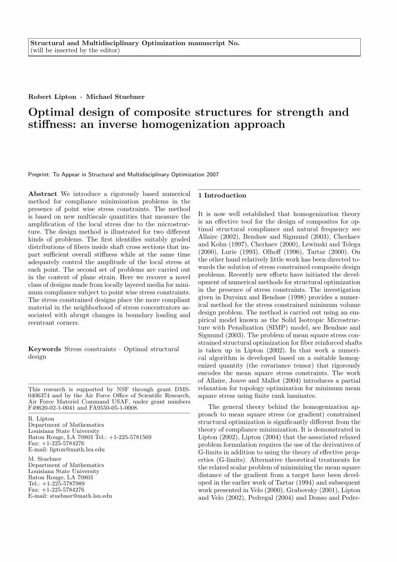
The level lines of the magnitude of the stress fieldin the actual fiber reinforced design is plotted in Figure6. It follows from Figures 4 and 6 that the point wisestress behavior is well represented by the level curvesof the macro stress modulation function for the optimalhomogenized design.
−1 −0.5 0 0.5 1−1
−0.8
−0.6
−0.4
−0.2
0
0.2
0.4
0.6
0.8
1The Final Density Distribution
0.2
0.25
0.3
0.35
0.4
0.45
0.5
0.55
0.6
0.65
Fig. 3 Grey scale plot of the local area fraction of fibers
θf (x).
−1 −0.5 0 0.5 1−1
−0.8
−0.6
−0.4
−0.2
0
0.2
0.4
0.6
0.8
1
0.5
210.5
0.5
1
1.5
2
Fig. 4 Contour plot of f(θf (x),∇φH(x))
4 Graded locally layered media and 2
dimensional elastic design
−1 −0.5 0 0.5 1−1
−0.8
−0.6
−0.4
−0.2
0
0.2
0.4
0.6
0.8
1
0
0.1
0.2
0.3
0.4
0.5
0.6
0.7
0.8
0.9
1
Fig. 5 Graded fiber design.
6
−1 −0.5 0 0.5 1−1
−0.8
−0.6
−0.4
−0.2
0
0.2
0.4
0.6
0.8
1
0.52
1
0.5
1
1.5
2
Fig. 6 Contour plot of the magnitude of the local stressamplitude.
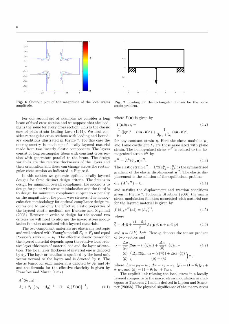
For our second set of examples we consider a longbeam of fixed cross section and we suppose that the load-ing is the same for every cross section. This is the classiccase of plain strain loading Love (1944). We first con-sider rectangular cross sections with loading and bound-ary conditions illustrated in Figure 7. For this case themicrogeometry is made up of locally layered materialmade from two linearly elastic components. The layersconsist of long rectangular fibers with constant cross sec-tion with generators parallel to the beam. The designvariables are the relative thicknesses of the layers andtheir orientation and these can change across the rectan-gular cross section as indicated in Figure 8.
In this section we generate optimal locally layereddesigns for three distinct design criteria. The first is todesign for minimum overall compliance, the second is todesign for point wise stress minimization and the third isto design for minimum compliance subject to a penaltyon the magnitude of the point wise stresses. The homog-enization methodology for optimal compliance design re-quires one to use only the effective elastic properties ofthe layered elastic medium, see Bendsøe and Sigmund(2003). However in order to design for the second twocriteria we will need to also use the macro stress modu-lation function associated with layered materials.
The two component materials are elastically isotropicand well ordered with Young’s moduli E1 > E2 and equalPoisson’s ratio ν1 = ν2. The effective elastic tensor forthe layered material depends upon the relative local rela-tive layer thickness of material one and the layer orienta-tion. The local layer thickness of material one is denotedby θ1. The layer orientation is specified by the local unitvector normal to the layers and is denoted by n. Theelastic tensor for each material is denoted by A1 and A2
and the formula for the effective elasticity is given byFrancfort and Murat (1987)
AL(θ1,n) =
A1 + θ1
[
(A1 − A2)−1 + (1 − θ1)Γ (n)
]−1, (4.1)
0 0.5 1 1.5 2 2.5 3
−1
−0.5
0
0.5
1
Fig. 7 Loading for the rectangular domain for the planestrain problem.
where Γ (n) is given by
Γ (n)η : η = (4.2)
1
µ1
(|ηn|2 − (ηn · n)2) +1
2µ1 + λ1
(ηn · n)2,
for any constant strain η. Here the shear modulus µ1
and Lame coefficient λ1 are those associated with planestrain. The homogenized stress σH is related to the ho-mogenized strain eH by
σH = AL(θ1,n)eH . (4.3)
The elastic strain eH = 1/2(uHi,j+uH
j,i) is the symmetrized
gradient of the elastic displacement uH . The elastic dis-placement is the solution of the equilibrium problem
div(
ALeH)
= 0, (4.4)
and satisfies the displacement and traction conditionsgiven in Figure 7. Following Stuebner (2006) the macrostress modulation function associated with material onefor the layered material is given by
f1(θ1, σH(x)) = |A1ζ|
2, (4.5)
where
ζ = A1η +(1 − θ1)
2A1(p ⊗ n + n ⊗ p) (4.6)
and η = (AL)−1σH . Here ⊗ denotes the tensor productof two vectors and
p =∆µ
〈µ〉(2ηn − trηn) +
∆κ
〈µ〉trηn − (4.7)
−〈κ〉
〈µ〉
(
∆µ(2ηn · n − trη) + ∆κtrη
〈µ〉 + 〈κ〉
)
n,
where ∆µ = µ2 − µ1, ∆κ = κ2 − κ1, 〈µ〉 = (1 − θ1)µ1 +θ1µ2, and 〈κ〉 = (1 − θ1)κ1 + θ1κ2.
The explicit link relating the local stress in a locallylayered composite to the macro stress modulation is anal-ogous to Theorem 2.1 and is derived in Lipton and Stueb-ner (2006b). The physical significance of the macro stress

7
Y
X
Fig. 8 The local layer thickness and oreintation can changeacross the cross section.
modulation function is that it provides an upper enve-lope on the local point wise stress amplitude inside ma-terial one when the layered microstructure is sufficientlyfine, see Lipton and Stuebner (2006b).
The design variables for this problem are the localarea fraction θ1(x) of material one used in the layers andthe layer orientation n(x). Here the layer orientation iswritten
n(x) = (sin γ(x), cos γ(x))
where γ(x) is the local layer angle. As before θ1(x) isfree to change inside the design domain subject to theconstraints given by (2.1), (2.2) and (2.3). Here the boxconstraints are given by 0 ≤ γ < π, 0.01 ≤ θ1 ≤ 0.99,∫
Ωθ1 = 0.4 × Area of Ω, E1 = 300Gpa, E2 = 30Gpa,
and ν1 = ν2 = 1/3. We reiterate that the box constraintson θ1 ensure that the design domain is completely filledwith composite material.
The overall compliance of the structure is given by
C(θ1, γ) =
∫
g · uH ds, (4.8)
where the integral is taken over the boundary of the de-sign domain and g is the boundary traction field. Thedesign problem for minimizing the overall compliance isgiven by
minθ1 γ
C(θ1, γ) ,
subject to constraints on θ1. (4.9)
This design problem is shown to be well posed in Liptonand Stuebner (2006b). The optimal area fraction distri-
bution for this problem is denoted by θ1 and is displayedin Figure 10. The level curves of the associated macrostress modulation function for material one are plottedin Figure 11.
For the second design problem we minimize the macrostress modulation function associated with the stiff ma-terial (material one) over the cross section. Here the func-tion to be optimized is given by
M(θ1, γ) =
∫
(f1(θ1, σH))p dx, (4.10)
where the integral is taken over the design domain and1 ≤ p < ∞. The design problem for minimizing the localstress inside material one is given by
minθ1 γ
M(θ1, γ) , (4.11)
subject to constraints on θ1.
This design problem is shown to be well posed in Liptonand Stuebner (2006b). For this example we choose p = 1.
The optimal area fraction distribution for this prob-
lem is denoted by θ1 and is displayed in Figure 12. Thelevel curves of the associated macro stress modulationfunction are plotted in Figure 13. Comparison of Figures11 and 13 show that the zones of high stress amplitudeare dramatically reduced by the minimum stress designdisplayed in Figure 12. While the overall compliance forthe minimum stress design is three times higher than theminimum compliance design, see Table 1.
−0.2 0 0.2 0.4 0.6 0.8 1 1.2
0
0.2
0.4
0.6
0.8
1
Fig. 9 Loading for the L-shaped domain for the plane strainproblem.
Last the compliance minimization subject to a penaltyon the pointwise stress inside material one is given by
minθ1 γ
C(θ1, γ) + ` × M(θ1, γ) ,
subject to constraints on θ1. (4.12)
where ` is the Lagrange multiplier for the stress con-straint.
The optimal area fraction distribution for this prob-
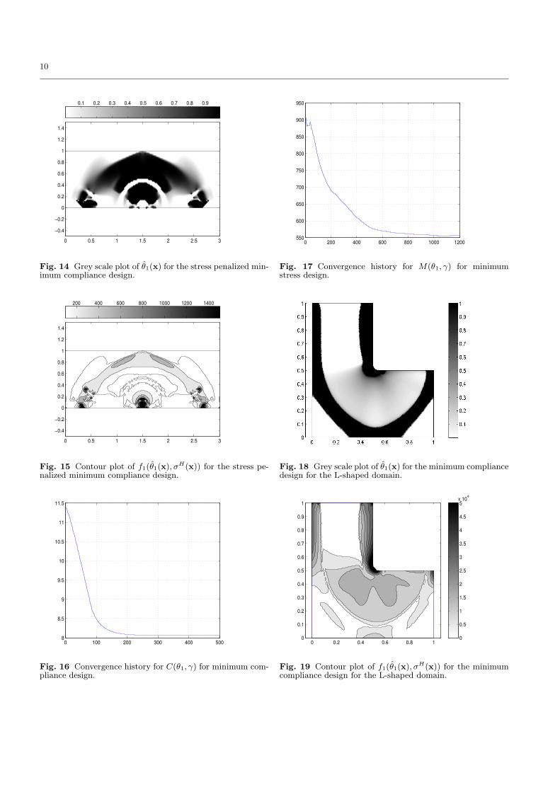
lem is denoted by θ1 and is displayed in Figure 14. Thelevel curves of the associated macro stress modulationfunction are plotted in Figure 15. Comparison of Fig-ures 11 and 15 show that the zones of high stress am-plitude seen in the design for compliance minimizationare dramatically reduced inside the design obtained fromthe stress penalized compliance minimization Figure 14.Table 1 shows that the overall compliance for the stresspenalized design is twice as high as the compliance min-imized design. It is interesting to note that the stresspenalized design surrounds the regions of high stress am-plitude with compliant material. This diminishes the ef-fect of the stress concentrations arising from the abruptchange in boundary loading.
In each of these examples we relaxed the constraint(2.3) and all of the optimizations were carried out usingsquare elements with bilinear shape functions for both
8
the elastic field variables and θ1. The runs were car-ried carried out for a FEM mesh consisting of roughly11,000 elements. The convergence histories for the mini-mum compliance design and minimum stress design aregiven in Figures 16 and 17.
The final two examples are carried out for the L-shaped design domain. This domain together with theboundary conditions and loading are shown in Figure 9.Here we compare the solutions to the minimum compli-ance design problem (4.9) with the minimum local stressdesign problem (4.11) posed on the L-shaped cross sec-tion. As seen in Figure 9, the L-shaped domain has arounded reentrant corner that provides a stress concen-tration.
The design problems are carried out subject to theconstraint that 40% of the cross-sectional area is occu-pied by material one. The optimal distribution of area
fraction of material one θ1 for the minimum compliancedesign problem (4.9) is displayed in Figure 18. The asso-ciated level curves of the macro stress modulation func-tion for material one are plotted in Figure 19. The op-
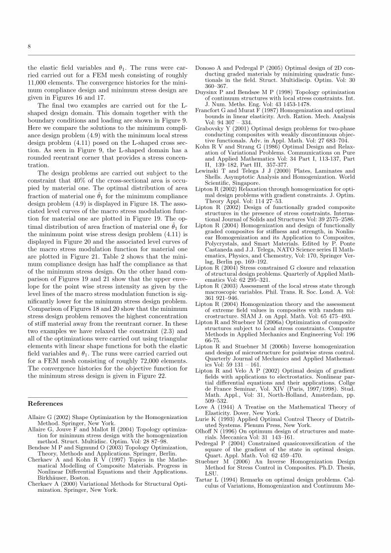
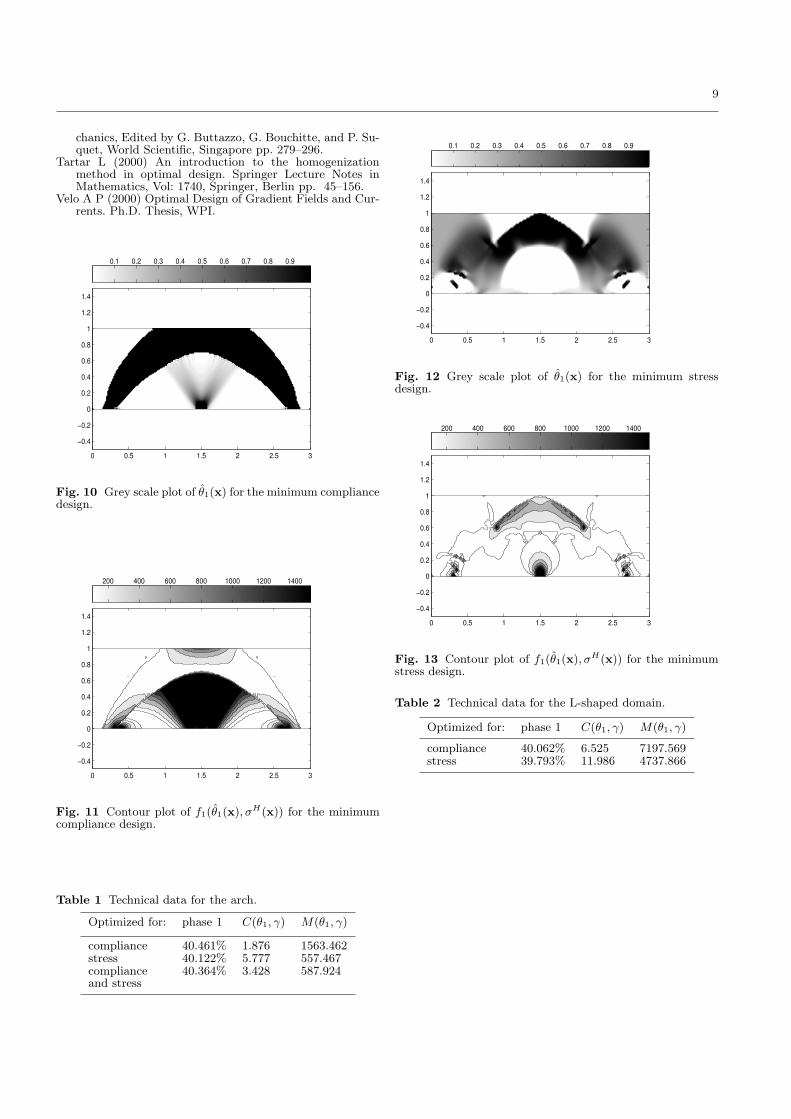
timal distribution of area fraction of material one θ1 forthe minimum point wise stress design problem (4.11) isdisplayed in Figure 20 and the associated level curves ofthe macro stress modulation function for material oneare plotted in Figure 21. Table 2 shows that the mini-mum compliance design has half the compliance as thatof the minimum stress design. On the other hand com-parison of Figures 19 and 21 show that the upper enve-lope for the point wise stress intensity as given by thelevel lines of the macro stress modulation function is sig-nificantly lower for the minimum stress design problem.Comparison of Figures 18 and 20 show that the minimumstress design problem removes the highest concentrationof stiff material away from the reentrant corner. In thesetwo examples we have relaxed the constraint (2.3) andall of the optimizations were carried out using triangularelements with linear shape functions for both the elasticfield variables and θ1. The runs were carried carried outfor a FEM mesh consisting of roughly 72,000 elements.The convergence histories for the objective function forthe minimum stress design is given in Figure 22.
References
Allaire G (2002) Shape Optimization by the HomogenizationMethod. Springer, New York.
Allaire G, Jouve F and Mallot H (2004) Topology optimiza-tion for minimum stress design with the homogenizationmethod. Struct. Multidisc. Optim. Vol: 28 87–98.
Bendsøe M P and Sigmund O (2003) Topology Optimization,Theory, Methods and Applications. Springer, Berlin.
Cherkaev A and Kohn R V (1997) Topics in the Mathe-matical Modelling of Composite Materials. Progress inNonlinear Differential Equations and their Applications.Birkhauser, Boston.
Cherkaev A (2000) Variational Methods for Structural Opti-mization. Springer, New York.
Donoso A and Pedregal P (2005) Optimal design of 2D con-ducting graded materials by minimizing quadratic func-tionals in the field. Struct. Multidiscip. Optim. Vol: 30360–367.
Duysinx P and Bendsøe M P (1998) Topology optimizationof continuum structures with local stress constraints. Int.J. Num. Meths. Eng. Vol: 43 1453-1478.
Francfort G and Murat F (1987) Homogenization and optimalbounds in linear elasticity. Arch. Ration. Mech. AnalysisVol: 94 307 – 334.
Grabovsky Y (2001) Optimal design problems for two-phaseconducting composites with weakly discontinuous objec-tive functionals. Adv. in Appl. Math. Vol: 27 683–704.
Kohn R V and Strang G (1986) Optimal Design and Relax-ation of Variational Problems. Communications on Pureand Applied Mathematics Vol: 34 Part I, 113-137, PartII, 139–182, Part III, 357-377.
Lewinski T and Telega J J (2000) Plates, Laminates andShells. Asymptotic Analysis and Homogenization. WorldScientific, Singapore.
Lipton R (2002) Relaxation through homogenization for opti-mal design problems with gradient constraints. J. Optim.Theory Appl. Vol: 114 27–53.
Lipton R (2002) Design of functionally graded compositestructures in the presence of stress constraints. Interna-tional Journal of Solids and Structures Vol: 39 2575–2586.
Lipton R (2004) Homogenization and design of functionallygraded composites for stiffness and strength, in Nonlin-ear Homogenization and its Application to Composites,Polycrystals, and Smart Materials. Edited by P. PonteCastaneda and J.J. Telega, NATO Science series II Math-ematics, Physics, and Chemestry, Vol: 170, Springer Ver-lag, Berlin pp. 169–192.
Lipton R (2004) Stress constrained G closure and relaxationof structural design problems. Quarterly of Applied Math-ematics Vol: 62 295–321.
Lipton R (2003) Assessment of the local stress state throughmacroscopic variables. Phil. Trans. R. Soc. Lond. A. Vol:361 921–946.
Lipton R (2004) Homogenization theory and the assessmentof extreme field values in composites with random mi-crostructure. SIAM J. on Appl. Math. Vol: 65 475–493.
Lipton R and Stuebner M (2006a) Optimization of compositestructures subject to local stress constraints. ComputerMethods in Applied Mechanics and Engineering Vol: 19666-75.
Lipton R and Stuebner M (2006b) Inverse homogenizationand design of microstructure for pointwise stress control.Quarterly Journal of Mechanics and Applied Mathemat-ics Vol: 59 131 – 161.
Lipton R and Velo A P (2002) Optimal design of gradientfields with applications to electrostatics. Nonlinear par-tial differential equations and their applications. Collgede France Seminar, Vol. XIV (Paris, 1997/1998). Stud.Math. Appl., Vol: 31, North-Holland, Amsterdam, pp.509–532.
Love A (1944) A Treatise on the Mathematical Theory ofElasticity. Dover, New York.
Lurie K (1993) Applied Optimal Control Theory of Distrib-uted Systems. Plenum Press, New York.
Olhoff N (1996) On optimum design of structures and mate-rials. Meccanica Vol: 31 143–161.
Pedregal P (2004) Constrained quasiconvexification of thesquare of the gradient of the state in optimal design.Quart. Appl. Math. Vol: 62 459–470.
Stuebner M (2006) An Inverse Homogenization DesignMethod for Stress Control in Composites. Ph.D. Thesis,LSU.
Tartar L (1994) Remarks on optimal design problems. Cal-culus of Variations, Homogenization and Continuum Me-
9
chanics, Edited by G. Buttazzo, G. Bouchitte, and P. Su-quet, World Scientific, Singapore pp. 279–296.
Tartar L (2000) An introduction to the homogenizationmethod in optimal design. Springer Lecture Notes inMathematics, Vol: 1740, Springer, Berlin pp. 45–156.
Velo A P (2000) Optimal Design of Gradient Fields and Cur-rents. Ph.D. Thesis, WPI.
0 0.5 1 1.5 2 2.5 3
−0.4
−0.2
0
0.2
0.4
0.6
0.8
1
1.2
1.4
0.1 0.2 0.3 0.4 0.5 0.6 0.7 0.8 0.9
Fig. 10 Grey scale plot of θ1(x) for the minimum compliancedesign.
0 0.5 1 1.5 2 2.5 3
−0.4
−0.2
0
0.2
0.4
0.6
0.8
1
1.2
1.4
200 400 600 800 1000 1200 1400
Fig. 11 Contour plot of f1(θ1(x), σH(x)) for the minimumcompliance design.
Table 1 Technical data for the arch.
Optimized for: phase 1 C(θ1, γ) M(θ1, γ)
compliance 40.461% 1.876 1563.462stress 40.122% 5.777 557.467compliance 40.364% 3.428 587.924and stress
0 0.5 1 1.5 2 2.5 3
−0.4
−0.2
0
0.2
0.4
0.6
0.8
1
1.2
1.4
0.1 0.2 0.3 0.4 0.5 0.6 0.7 0.8 0.9
Fig. 12 Grey scale plot of θ1(x) for the minimum stressdesign.
0 0.5 1 1.5 2 2.5 3
−0.4
−0.2
0
0.2
0.4
0.6
0.8
1
1.2
1.4
200 400 600 800 1000 1200 1400
Fig. 13 Contour plot of f1(θ1(x), σH(x)) for the minimumstress design.
Table 2 Technical data for the L-shaped domain.
Optimized for: phase 1 C(θ1, γ) M(θ1, γ)
compliance 40.062% 6.525 7197.569stress 39.793% 11.986 4737.866
10
0 0.5 1 1.5 2 2.5 3
−0.4
−0.2
0
0.2
0.4
0.6
0.8
1
1.2
1.4
0.1 0.2 0.3 0.4 0.5 0.6 0.7 0.8 0.9
Fig. 14 Grey scale plot of θ1(x) for the stress penalized min-imum compliance design.
0 0.5 1 1.5 2 2.5 3
−0.4
−0.2
0
0.2
0.4
0.6
0.8
1
1.2
1.4
200 400 600 800 1000 1200 1400
Fig. 15 Contour plot of f1(θ1(x), σH(x)) for the stress pe-nalized minimum compliance design.
0 100 200 300 400 5008
8.5
9
9.5
10
10.5
11
11.5
Fig. 16 Convergence history for C(θ1, γ) for minimum com-pliance design.
0 200 400 600 800 1000 1200550
600
650
700
750
800
850
900
950
Fig. 17 Convergence history for M(θ1, γ) for minimumstress design.
Fig. 18 Grey scale plot of θ1(x) for the minimum compliancedesign for the L-shaped domain.
0 0.2 0.4 0.6 0.8 10
0.1
0.2
0.3
0.4
0.5
0.6
0.7
0.8
0.9
1
0
0.5
1
1.5
2
2.5
3
3.5
4
4.5
5x 10⁴
Fig. 19 Contour plot of f1(θ1(x), σH(x)) for the minimumcompliance design for the L-shaped domain.

11
Fig. 20 Grey scale plot of θ1(x) for the minimum stressdesign for the L-shaped domain.
0 0.2 0.4 0.6 0.8 10
0.1
0.2
0.3
0.4
0.5
0.6
0.7
0.8
0.9
1
0
0.5
1
1.5
2
2.5
3
3.5
4
4.5
5x 10⁴
Fig. 21 Contour plot of f1(θ1(x), σH(x)) for the minimumstress design for the L-shaped domain.
0 50 100 150 200 250 300 350 4000
0.5
1
1.5
2
2.5x 10⁵
Fig. 22 The convergence history for M(θ1, γ) for minimumstress design for the L-shaped domain.