michael schneider - optical design manufacturing - ttk500 - ug01 - 04-16-13.pdf · odm...
TRANSCRIPT


ODM ATT-LTE-TTK500-UG01-4.13
2
WELCOME
A message from the founder:
Thank you for choosing ODM to support your needs for the testing and inspection of fiber optic cable connectors. ODM provides technicians and installers with accurate, cost-effective test solutions, comprehensive training, and the expertise of our excellent technical support staff.
This user guide is provided for your reference in the testing, inspection and documentation of the dB loss in the installation process for optical fiber cabling. It provides industry accepted connector cleaning guidelines, fiber optic connector endface inspection procedures, and fiber optic loss measurement techniques.
Should you need additional help, please contact a member of our knowledgeable and responsive technical support team via the contact information provided at the end of this manual. We are here to answer your questions, provide guidance and help troubleshoot any problems you may be having with your installation. Thanks again for your business.
Sincerely,
Michael Schneider
Michael Schneider Founder, Optical Design Manufacturing, Inc.

ODM ATT-LTE-TTK500-UG01-4.13 3
TABLE OF CONTENTS
WELCOME .................................................................................................................................................................................... 2
TABLE OF CONTENTS ................................................................................................................................................................... 3
INTRODUCTION ............................................................................................................................................................................ 4
1. TEST SITE OVERVIEW ............................................................................................................................................................... 5
2. REQUIRED EQUIPMENT FOR INSPECTION AND dB LOSS MEASUREMENT .............................................................................. 6
TTK 500 TEST KIT ........................................................................................................................................................................ 6
3. FIBER OPTIC ENDFACE INSPECTION AND CLEANING PROCEDURES....................................................................................... 10
INTRODUCTION .......................................................................................................................................................................... 10
CLEANING GUIDE AND CRITERIA TEMPLATE ...................................................................................................................................... 10
FIRST INSPECTION AND DRY CLEANING ............................................................................................................................................ 12
SECOND INSPECTION AND DRY CLEANING ......................................................................................................................................... 12
THIRD INSPECTION ...................................................................................................................................................................... 13
FIRST WET/DRY CLEANING OF ENDFACE CONNECTORS ....................................................................................................................... 13
4. INSPECTION AND dB LOSS TEST PROCEDURE ........................................................................................................................ 14
INTRODUCTION........................................................................................................................................................................... 14
VISUAL INSPECTION OF ENDFACE CONNECTORS USING THE VIS 300 VIDEO INSPECTION SCOPE .................................................................. 14
CALIBRATION AND dB LOSS MEASUREMENT ................................................................................................................................... 17
4. dB LOSS REPORTING .............................................................................................................................................................. 19
5. CLOSEOUT DOCUMENTATION ............................................................................................................................................... 21
6. TECHNICAL SUPPORT AND FREQUENTLY ASKED QUESTIONS ............................................................................................... 23
FREQUENTLY ASKED QUESTIONS ..................................................................................................................................................... 23
TECHNICAL SUPPORT ................................................................................................................................................................... 24
APPENDIX A – GLOSSARY OF TERMS ......................................................................................................................................... 25

ODM ATT-LTE-TTK500-UG01-4.13
4
INTRODUCTION
This user guide contains the following sections:
Section 1 – “Test Site Overview” describes the two types of installations applicable to the test
procedures outlined in this guide.
Section 2 – “Required Test Equipment for Connector Inspection and dB Loss Testing” provides detailed
information on the TTK 500 Test Kit and how to use it for AT & T LTE installation.
Section 3 – “Fiber Optic Endface Inspection and Cleaning Procedures” outlines fiber optic connector
endface quality prior to testing installed systems.
Section 4 – “Inspection and dB Loss Test Procedure” describes how to clean, visually inspect and test the
dB loss of the AT & T LTE optical cable.
Section 5 – “Closeout Documentation” explains how to save and report dB loss values.
Section 6 – “Technical Support and Frequently Asked Questions” provides the ODM contact information
for technical support and answers to several frequently asked questions.
Appendix A – The “Glossary” defines important terms used throughout this manual.
NOTE: All ODM measurement equipment conforms to NIST traceable standards. All connector cleaning guidelines conform to IEC 61300-3-35 Ed. 1.0.

ODM ATT-LTE-TTK500-UG01-4.13 5
1. TEST SITE OVERVIEW
Two types of installations are possible: base to rooftop and base to tower top. Both installations utilize the same test procedure. Tower top installations require a certified climber to perform the test procedures associated with the tower top. The illustration below shows the typical installation to be tested.

ODM ATT-LTE-TTK500-UG01-4.13
6
2. REQUIRED EQUIPMENT FOR INSPECTION AND dB LOSS MEASUREMENT
TTK 500 TEST KIT
This section provides details on the equipment required to perform the following tasks associated with AT&T
LTE installation:
System dB loss
Portable video inspection of all optical fiber connectors
Connector cleaning kit for the complete endface cleaning of all connector interfaces.
USB software for closeout documentation
TTK 500 Test Kit
19
55
10
18
5
11
0
8
9
16
55
12 13 15
17
55 14
55
6
55
4
55
7
55
3
55
1
55 2
55

ODM ATT-LTE-TTK500-UG01-4.13 7
MODEL DESCRIPTION APPLICATION QTY.
1 DLS 350M Dual LED Source 850nm/1300nm with SC Connector output
Multimode fiber light source used w/RP 460 power meter for dB loss test
1
2 DLS 355M Dual Laser Source 1310nm/1550nm SC Conn.
Single mode fiber light source used w/RP 460 power meter for dB loss test
1
3 RP 460-02 Power Meter w/ Zero dB/Set Ref, 1000 data point store & USB download
Power meter used with light source for dB loss measurement and storage, also offers USB transfer to computer for closeout documentation
1
4 VIS 300 Display Monitor
VIS 300 3.5” display monitor with USB output. Includes padded pouch and AC Charger.
Portable video monitor to view connector endface and ensure connectors meet IEC 825 standard after proper cleaning procedures.
1
5 VIS 300 Connector Inspection Scope
Inspection probe with changeable tips. Portable inspection device to view connector endface and ensure connectors meet IEC 825 standard after proper cleaning procedures.
1
6 AC 029 LC Adapter for RP460 Optical Power Meter
Allows LC connection to optical power meter 1
7 AC 300 CR2 Battery Kit / 5 per pack Spare Battery Kit 1
8 AC 500 LC-SC, SM, 9/125 Fiber, 1 Meter Cable Fiber patch cord to allow calibration of test instruments for complete system dB loss test
1
9 AC 502 LC-LC, SM, 9/125 Fiber, 1 Meter Cable Fiber patch cord to allow calibration of test instruments for complete system dB loss test
1
10 AC 550 LC-SC, MM 50/125 fiber, 1 Meter Cable Fiber patch cord to allow calibration of test instruments for complete system dB loss test
1
11 AC 552 LC-LC, MM 50/125 fiber, 1 Meter Cable Fiber patch cord to allow calibration of test instruments for complete system dB loss test
1
12 AC 600 SC-SC Adapter SC adapter to allow legacy DLS 355 to test dB loss 1
13 AC 601 LC-LC Adapter duplex LC adapter to allow access to LC duplex connector on optical jumper cable
2
14 CK 125 Cleaning Kit - Includes fiber cleaning solution, wipes, 1.25mm swabs, 2.5mm swabs good for 300 connectors and adapters
Complete Wet/Dry cleaning system for all connector endfaces including ODC connectors and System/RF modules (300+ cleanings)
1
15 AC 089 One Click Connector Cleaner Single unit to clean Plug and Socket ODC and other MIL/AERO 1.25 mm connectors.
1
16 AC 800 USB Cable For downloading testing results from VIS 300 and RP 460 to laptop computer
2
17 AC 2100 Instruction SVF software Contains VIS 300 and RP 460 software, user guides and operating instructions
1
18 AC 2015 Grading Template Used for field inspection on VIS 300 for connector Pass/Fail analysis.
1
19 AC 012 ODM 17" Hard Carry Case Protective carry case for all instruments and accessories except for AC 060
1
TTK 500 Test Kit – Bill of Materials

ODM ATT-LTE-TTK500-UG01-4.13
8
AC 065 Accessory Kit for AT & T – LTE
AC 065 Bill of Materials
MODEL DESCRIPTION APPLICATION QTY. 1 VF 610 635nm red laser in ODM
Single Instrument Pouch
Laser used to detect breaks and high bend losses in optical fiber
1
2 AC 523 Assembly LC Clipped – LC and SC cable
1
3 AC 4500 Loopback with Lanyard Calibration and dB test module
1
3
2
16
6

ODM ATT-LTE-TTK500-UG01-4.13 9
Accessory Kit for Ericsson/ODC Cable
Accessory Kit for Ericsson/ODC Cable – Bill of Materials
MODEL DESCRIPTION APPLICATION QTY. 1 84126476 Fiber Optic assembly, ODC-2 Plug to LC
Duplex Reference cable to allow testing of optical ODC2 plug cable
1
2 84122957 Fiber Optic assembly, ODC-2 socket to LC Reference cable to allow testing of optical ODC2 socket cable
1
3 AC 200-S Torque wrench for H & S cables Provides proper torque of mating nut on H & S ODS interconnections
1
4 AC 153 ODC Adapter Kit, includes ODC pin and socket adaptors
Allows inspection of ODC plug and ODC socket optical endface
1
5 AC 523 Assembly LC clipped – LC and SC Connectors Cable
1
6 AC 4500 Loopback with lanyard Calibration and dB test module 1
7 AC 014 Soft pouch For protection and storage of cables and equipment
1
5
7
66
6
3
2 16
6
4

ODM ATT-LTE-TTK500-UG01-4.13
10
WARNING: When working with fiber optic cables, always assume the fiber is live. Invisible laser radiation can cause irreversible injury to the human eye. Never look into the end of an exposed fiber optic cable, bulkhead or optical light source. The use of non-direct viewing devices, such as the VIS 300 Video Inspection Scope, is recommended.
3. FIBER OPTIC ENDFACE INSPECTION AND CLEANING PROCEDURES
INTRODUCTION
Contamination of fiber connector surfaces is the top reason for link failure in the installation of optical fiber
cable. It is imperative for installers and technicians to follow the guidelines in this section in order to ensure the
quality of the connector endface prior to testing installed systems.
As per document IEC 61300-3-35 Ed 1.0, the following inspection and cleaning procedures should be used
before installing or testing any fiber optic jumper or trunk cable. Only use approved test sets, inspection
equipment, and cleaning supplies. Any moveable debris on a fiber optic connector endface is not allowed. After
three dry cleaning attempts to remove debris, a “wet/dry” cleaning process is recommended.
CLEANING GUIDE AND CRITERIA TEMPLATE
Use the ODM grading overlay template in conjunction with Fiber Endface Criteria Table (both are shown on the
next page) to determine acceptability of the fiber endface. The ODM Video Inspection Software (VIS IMS)
running on a Windows PC also provides grading template and criteria table.
Diameter obstructions of 2µm, 5µm and 10µm are provided in the outer most area of the zone grading overlay.
The circle defining the limit of the contact zone has a 3µm line width.
To determine the correct zone, place the grading template on top of the VIS 300 display and align the cladding
zone with the cladding on the display. If obstructions and/or scratches are visible in Zones A, B, C or D, place
each sized reference obstruction over the obstruction in question to determine acceptability according to the
grading criteria table. Place the 3µm contact zone limit circle on top of any scratches to determine width
acceptance of the scratch according to the table below.

ODM ATT-LTE-TTK500-UG01-4.13 11
Fiber EndFace Criteria Table for UPC Polished Connectors
Single Mode Fiber, RL ≥ 45dB According to IEC 61300-3-35
Zone Description Diameter Allowable Scratches (Width)
Allowable Defects (Diameter)
A Critical Zone 0µm to 25µm None None
B Cladding Zone 25µm to 120µm No limit ≤ 3 µm None > 3µm
No limit < 2µm 5 from 2µm to 5µm None > 5µm
C Adhesive Zone 120µm to 130µm No limit No limit
D Contact Zone 130µm to 250µm No limit None ≥ 10µm
To determine if obstructions and/or scratches are present in the relevant zones, align the grading template to the cladding area.
This example shows the comparison of a 2µm zone template obstruction with obstruction in the cladding zone.
This shows the 3µm line width contact zone with a scratch across the contact and cladding zones.

ODM ATT-LTE-TTK500-UG01-4.13
12
NOTE: Refer to AT&T inspection and cleaning documents ATT-TELCO-002-200-381 and ATT-TP-76461.
FIRST INSPECTION AND DRY CLEANING
Inspect the fiber optic cable endface using the VIS 300 with probe and LC adapter tip. If there are no visible
defects and the endface is clean of debris and scratches, the connector is acceptable for connection. If the
endface shows debris, scratches, or defects, complete the first dry clean procedure. Use the AC 094 LC
Connector Cleaner for cleaning LC connectors. One push/click is generally acceptable. If cleaning an LC bulkhead
adapter is required, use the AC 094 LC Connector Cleaner. See image # 3 below.
SECOND INSPECTION AND DRY CLEANING
Perform second endface inspection with VIS 300-USB Video Inspection Scope.
If there is no debris, scratches or defects on the endface, then the connector is acceptable for
connection.
If the endface shows the debris has moved, perform the second dry clean method.
If all debris was unchanged or unmoved, the endface must be graded.
If grading determines the endface is acceptable, then make your connection.
If grading determines the endface is unacceptable, perform second dry cleaning.
3 Remove clear plastic cap and push LC Cleaner into bulkhead. Clean with one push/click.
2 Push LC Cleaner into LC Connector
1 Use the VIS 300 inspection scope with LC adapter tip to test the endface for debris and scratches.

ODM ATT-LTE-TTK500-UG01-4.13 13
THIRD INSPECTION
Perform third endface inspection with VIS 300-USB Video Inspection Scope.
If the endface shows no debris, scratches or defects, the connector is acceptable for connection.
If debris, scratches or defects are still present, proceed to the next step: “First Wet/Dry Cleaning of
Endface Connectors” and refer to AT&T document ATT-TP-76461.
FIRST WET/DRY CLEANING OF ENDFACE CONNECTORS
The SqR™ Compact EndFace Cleaning Tool pad supplied is designed to be used in conjunction with the Electro
Wash MX Fiber Optic Cleaning Pen. For correct use of the cleaning pad and pen, follow these instructions:
NOTE: To verify the most recent test, inspection, and closeout documentation requirements, or if cleaning does not produce acceptable results, contact [email protected].
1 Place the protective barrier (attached card with arrows) under the first cleaning sheet.
2 With the Electro-Wash MX Pen, apply a coin-sized spot of solvent to the exposed wipe near the top of the sheet separator. Be careful not to apply too much solvent.
3 Hold the end of the connector at a 90-degree angle and gently press the connector into the wet spot on the wipe.
4 Glide the connector from the wet spot (which cleans the connector) to the bottom of the wipe (which dries the connector).

ODM ATT-LTE-TTK500-UG01-4.13
14
4. INSPECTION AND dB LOSS TEST PROCEDURE
INTRODUCTION
This section outlines steps to visually inspect, clean, and test the dB loss of the AT&T LTE optical cable.
VISUAL INSPECTION OF ENDFACE CONNECTORS USING THE VIS 300 VIDEO INSPECTION SCOPE
Typical installations will require the inspection, grading and reporting of the base end of the ATT LTE main trunk
cable LC optical connector endfaces.
Current installations include 24 or 36 individual fibers per cable. The instructions contained in this document
are applicable to a 24-fiber cable installation.
Connect the probe with 1.25mm adapter to the
VIS 300 Monitor (shown above). Connect the
monitor to the laptop computer with the
supplied USB cable and turn on the VIS 300 USB.
Open the Image Manager Software Program on
the laptop. Enter the site information on the
right side of the Image Manager Software
window (shown at right). This information will
be generic for all images saved and should
remain exactly the same for the remainder of
the procedure.

ODM ATT-LTE-TTK500-UG01-4.13 15
If the endface image does not pass the criteria of IEC 61300-3-35 Ed 1.0 as described in Section 4 (in the Cleaning
Guide and Criteria Template sub-section), follow the instructions in that section to clean the connector endface,
if necessary, and re-inspect. To go back to a live image, click on the Full Field of View button.
6 The smaller window labeled “Drag Here” is a reference to gauge or measure debris and scratches. To place anywhere on the image, click and hold the left mouse button on the Drag Here title bar.
5 To adjust the position of the grading circles, use the arrow buttons on the keyboard. To enlarge or reduce the diameter of the grading circles, use the mouse scrolling wheel or hold the Control key and Up and Down arrows. The double yellow circles define the adhesive zone and should be sized so that the larger yellow circle is just outside of the adhesive zone and the smaller yellow circle is just inside of the adhesive zone.
4 Position the mouse pointer on the center of the core and cladding area then click the right mouse button to center the grading circles.
3 Click the Show Grading button to display the grading template on the connector image.
1 Insert your first fiber into the VIS probe. Adjust the focus on the probe until the Image Manager Software shows a clear image.
2 Click the Magnify and Center button to zoom in on the core and cladding area of the image. This will display a still image.

ODM ATT-LTE-TTK500-UG01-4.13
16
9 To create paired reports for closeout documentation requirements click the first image 1A, hold the control key down and click the second image 1B at the bottom of the Image Manager window. This will highlight both images.
10 To create paired reports for closeout documentation requirements click the first image 1A, hold the control key down and click the second image 1B at the bottom of the Image Manager window. This will highlight both images.
7 Once you have a passing connector endface image with the grading circles in place in the Magnify and Center view, click the Pass button to place a Pass Stamp on the image.
8 Click on the Change Folder button to create a new folder to save your images to. Name the folder with the site number. Click the Capture Image button to bring up a Save As dialog window. Name this file 1A. The number refers to the fiber pair (1 – 12); the letter refers to the specific fiber in that pair (A or B). Repeat the grading and capture image procedure until all 24 connector endface images have been saved.

ODM ATT-LTE-TTK500-UG01-4.13 17
CALIBRATION AND dB LOSS MEASUREMENT
The dB loss test includes testing of all fibers pairs in the AT&T LTE main trunk cable with 3 additional loss tests
with the sector jumper cables attached to the main trunk. This test procedure requires a loopback style setup,
which tests two fibers at once. A 12-pair installation will have a total of 15 dB loss readings. An 18-pair
installation will have a total of 21 dB loss readings.
1 Before beginning any testing, be sure that the RP 460 internal memory is cleared. Press the Save and Wavelength (λ) buttons at the same time. The display will read “0000” for a moment then go back to the live reading.
2 Connect the RP 460, DLS 355, LC
Duplexed to LC SC yellow single mode
paired cable and the loopback module.
Power on both the RP 460 and DLS 355.
Set both units to 1310nm. Set the RP 460
to the dBm mode.
3 Make sure the RP 460 is reading between -3dBm and -4dBm. If the reading is less than -4dBm such as -5dBm, inspect and clean all optical fiber connector endfaces, including the output connector of the DLS 355.
4 Press and hold the dB/dBm key for 4 seconds or until you hear a second audible beep. The RP 460 will now display 0.00 dB. Fluctuations of 0.05 dB are normal. Remove the loopback module with LC duplex bulkhead adapter from the paired cable.

ODM ATT-LTE-TTK500-UG01-4.13
18
5 Connect the loopback to the squid end or tower top end of the first pair of the main trunk cable.
6 Connect the paired calibration cable end that was attached to the loopback to the first pair of the main trunk cable at the base of the tower using an LC-LC duplex bulkhead adapter. Maximum allowable loss is 3dB. When you have an acceptable loss reading, press the Save button on the RP 460.
Repeat loss test saving for the remaining fiber
pairs of the main trunk cable.
7 After all main trunk pairs have been tested and saved, connect the 3 sector jumper fiber pairs to their respective pairs of the main trunk cable at the squid.
8 Connect the loopback module to the radio end of the first sector jumper pair.
9 Connect the paired cable with the RP 460 and DLS 355 to the first pair of the main trunk cable at the base of the tower (see image at right). Maximum allowable loss is 3dB. When you have an acceptable loss reading, press the Save button on the RP 460. Repeat loss test saving for the remaining 2 sectors.
ODM ATT-LTE-TTK500-UG01-4.13 19
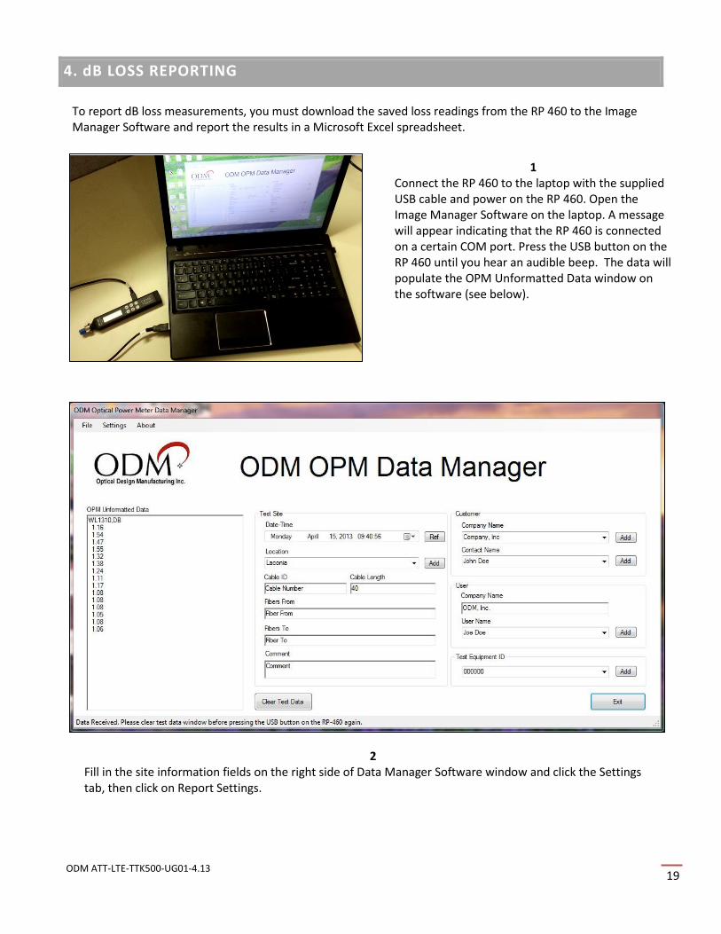
4. dB LOSS REPORTING
1 Connect the RP 460 to the laptop with the supplied USB cable and power on the RP 460. Open the Image Manager Software on the laptop. A message will appear indicating that the RP 460 is connected on a certain COM port. Press the USB button on the RP 460 until you hear an audible beep. The data will populate the OPM Unformatted Data window on the software (see below).
To report dB loss measurements, you must download the saved loss readings from the RP 460 to the Image Manager Software and report the results in a Microsoft Excel spreadsheet.
2 Fill in the site information fields on the right side of Data Manager Software window and click the Settings tab, then click on Report Settings.

ODM ATT-LTE-TTK500-UG01-4.13
20
3 Set the maximum limit for 1310nm to 3.0 and click the enable and dB check boxes. If you are reporting a 12-pair installation, click the AT&T LTE Cable Color or Custom Configuration for Reports selection then Click the OK button.
4 Click the File tab at the top of the Data Manager software window and then click the Export to Excel selection. The loss readings will be reported in a new Excel window. Use Excel to save the file. See enlarged image on next page.

ODM ATT-LTE-TTK500-UG01-4.13 21
5. CLOSEOUT DOCUMENTATION
Fiber test and inspection closeout information will include a dB loss report from the Data Manager Software
and the 12 or 18 paired report JPEG files from the Image Manager software. A sample dB loss report is shown
below. An example of the paired JPEG report files is shown on Page 21. For more information, please consult
your local construction manager or contact ODM (Refer to Page 23 for contact information).

ODM ATT-LTE-TTK500-UG01-4.13
22

ODM ATT-LTE-TTK500-UG01-4.13 23
6. TECHNICAL SUPPORT AND FREQUENTLY ASKED QUESTIONS
FREQUENTLY ASKED QUESTIONS
We have provided the following questions and answers to help address the most common installation questions and issues. If you need further guidance, please contact our technical support team.
Q. What is the difference between dBm and dB?
A. dB (decibel) is a unit used to express values of power level on a logarithmic scale. dBm is an absolute optical power measurement referenced to 1 milliwatt of optical energy. It is the starting measurement of the dB loss measurements. For more information, see the Glossary at the end of this guide.
Q. Why do I get a negative dB reading? A. This reading is often the result of the calibration cables not being as clean and aligned as the cable
under measurement. This negative reading is common while measuring short-distance cables (less than 100 feet). Always keep reference patch cables clean and free from contamination. Negative readings greater than -.5dB are indicative of other problems in the measurement. In this case, call our technical support group at (603) 524-8350.
Q. Will my reading be saved in the RP 460 memory while the battery is changed? A. Yes the RP 460 will retain measurements in a non-volatile memory.
Q. Why do I need to inspect all fiber connections? A. Short-distance fiber systems typically fail as a result of contaminated connector ends. More than 90
percent of all failures are due to endface debris. The use of a Video Inspection Scope ensures quality in a connected fiber system.

ODM ATT-LTE-TTK500-UG01-4.13
24
TECHNICAL SUPPORT
If you need guidance or have specific questions about any procedures or guidelines in this guide, please contact
our technical support team at the contact information below:
During Business Hours: 8 a.m. to 5 p.m. Eastern Standard Time. Please call us at (603) 524-8350.
Evenings/Weekends:
Email us at [email protected]. Please include your phone number and we will return your call within 2 hours.
By Mail:
Optical Design Manufacturing 143 Lake Street Laconia, NH USA 03246
Visit our website: www.odm-inc.com
By FAX: (603) 524-8332

APPENDIX A – GLOSSARY OF TERMS
Attentuation
Optical power loss as measured in decibels. Attentuation is the main parameter field-tested in optical-fiber systems. Cables, connectors, splices and patch cords contribute to a system`s overall attenuation. Additional loss may also be induced by tight bends or excessive forces placed on the cable during transportation and installation.
Decibel (dB)
Unit used to express values of power level on a logarithmic scale. The power level is always relative to a
reference power P0 where P and P0 are expressed in the same linear units:
L P/P0=10 • log10(P/P0) dB
Related:
dBc: decibel relative to a carrier level
dBµ: decibel relative to microwatt
dBm: decibel relative to milliwatt
End-to-End Attentuation
A measure of the optical power loss between cable termination points, end-to-end attenuation tests
quantitatively measure the installed performance of a cable system and its components.
Multimode
A waveguide through which several modes propagate. The core diameter is much larger than the wavelength of
light (typically 50 or 62.5 mm). Commonly used with LED sources for lower speed, short distance links.
Single mode
A small-core optical wave guide through which only one mode propagates. The typical core diameter is 8 to 12
microns.