michael m. wolf april 20, 2005 - sandia national...
TRANSCRIPT

1
Intro to Mesh Generation
Michael M. WolfApril 20, 2005

2
Overview
• Introduction to Mesh Generation• Mesh Quality• Serial Meshing Methods
– Quadtree/Octree– Advancing Front – Delaunay
• Parallel Mesh Generation– Why Parallel?– Categorization Parallel methods– Subdomains, interfaces, separators
• CSAR Mesh Repair in Rocket Simulation
3
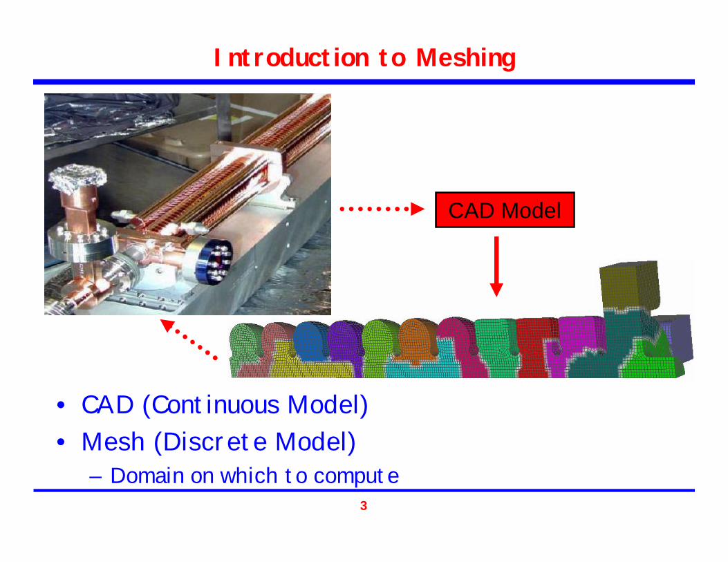
Introduction to Meshing
• CAD (Continuous Model)• Mesh (Discrete Model)
– Domain on which to compute
CAD Model
4
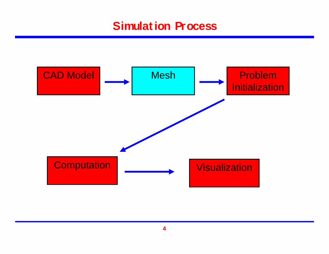
Simulation Process
CAD Model Mesh Problem Initialization
Computation Visualization

5
Adaptive Simulation Process
CAD Model Mesh Problem Initialization
Computation
Visualization
Error Estimation
Remesh/Refine/Repair
>ε
<ε
6
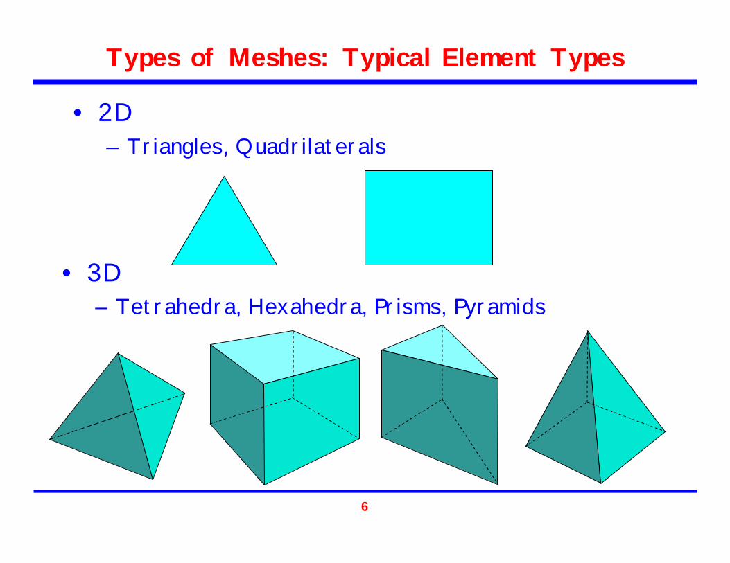
Types of Meshes: Typical Element Types
• 3D– Tetrahedra, Hexahedra, Prisms, Pyramids
• 2D– Triangles, Quadrilaterals
7
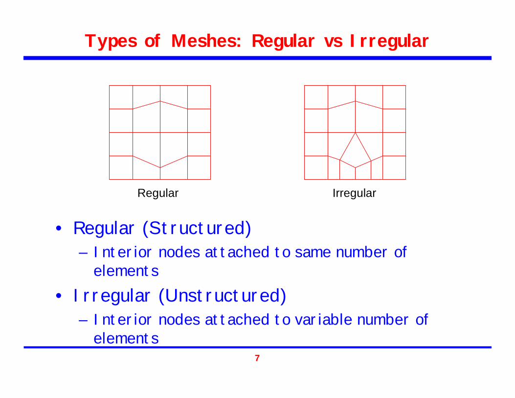
Types of Meshes: Regular vs Irregular
• Regular (Structured)– Interior nodes attached to same number of
elements• Irregular (Unstructured)
– Interior nodes attached to variable number of elements
Regular Irregular

8
Mesh Quality
• Poor quality elements often yield poor solutions
• Usually regular tetrahedron (4 equilateral faces) is prototypic good element
• How to quantify “Good” element– Dihedral angles– Volume– Skew– Algebraic means– Etc.
9
Overview
• Introduction to Mesh Generation• Mesh Quality• Serial Meshing Methods
– Quadtree/Octree– Advancing Front – Delaunay
• Parallel Mesh Generation– Why Parallel?– Categorization Parallel methods– Subdomains, interfaces, separators
• CSAR Mesh Repair in Rocket Simulation

10
Serial Meshing Methods
• Going to present 2D versions of methods but 3D equivalents are similar
• Focus on Triangle methods but there are numerous interesting Quad methods
11
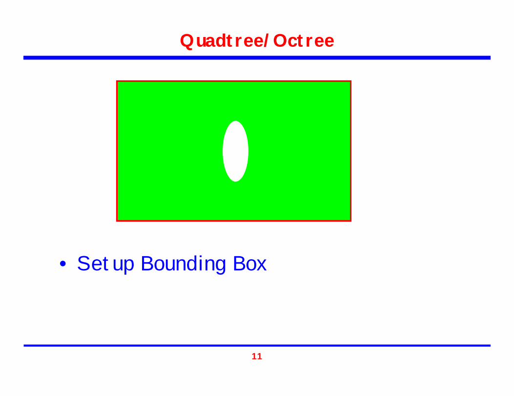
Quadtree/Octree
• Setup Bounding Box
12
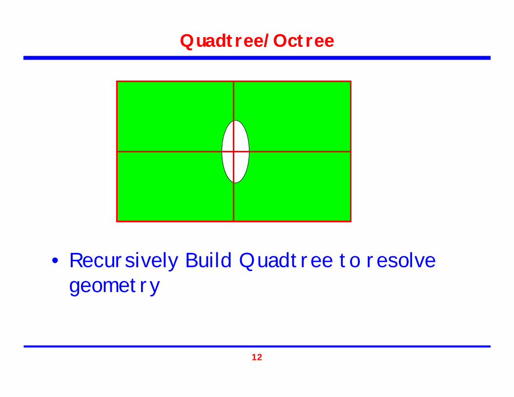
Quadtree/Octree
• Recursively Build Quadtree to resolve geometry

13
Quadtree/Octree
• Recursively Build Quadtree to resolve geometry

14
Quadtree/Octree
• Recursively Build Quadtree to resolve geometry

15
Quadtree/Octree
• Add nodes to: – Intersection of 2 quadtree lines – Intersection of boundary and quadtree line
• Remove nodes not outside boundary

16
Quadtree/Octree
• Mesh Structure using nodes with triangles
17
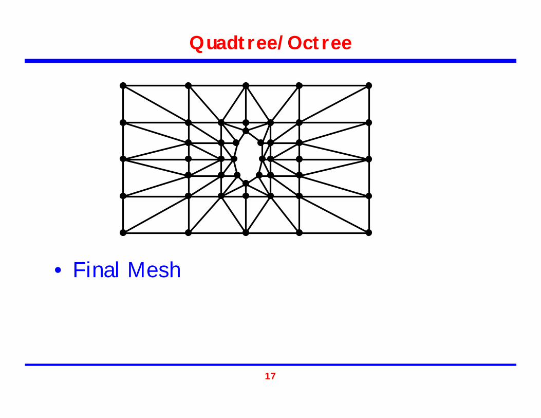
Quadtree/Octree
• Final Mesh

18
Advancing Front

19
Advancing Front
• Place nodes around boundary.

20
Advancing Front
• Front initially set to be boundary.
21
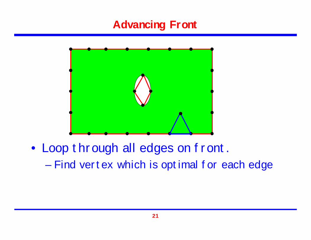
Advancing Front
• Loop through all edges on front.– Find vertex which is optimal for each edge

22
Advancing Front
• Create triangle• Remove edge from front• Add new edges to front

23
Advancing Front
• Check radius around optimal node for nodes currently on front
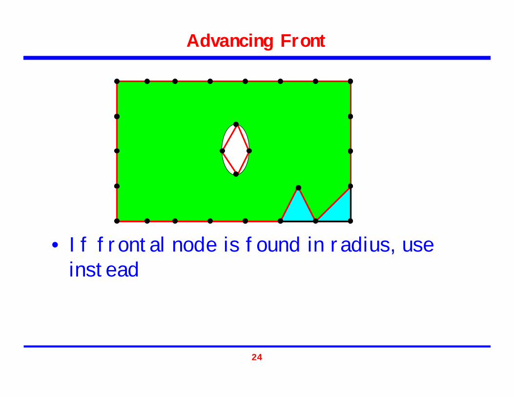
24
Advancing Front
• If frontal node is found in radius, use instead

25
Advancing Front
• If choice between multiple nodes, chose best quality element
• Continue until finished

26
Delaunay

27
Delaunay
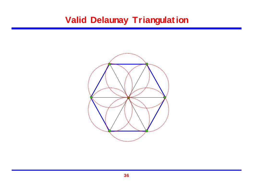
Empty Circle (Sphere) Property: No other vertex is contained within the circumcircleof any triangle
28
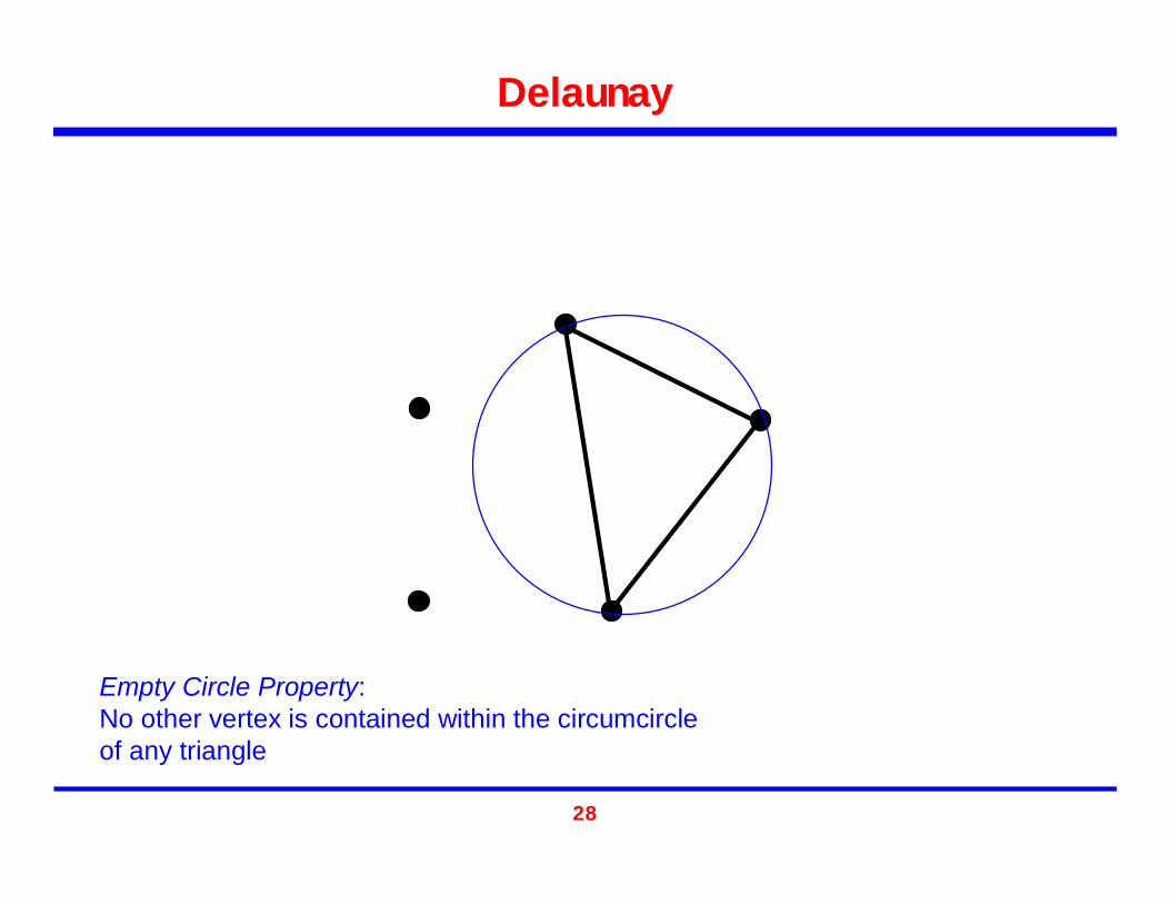
Delaunay
Empty Circle Property: No other vertex is contained within the circumcircleof any triangle

29
Delaunay
30
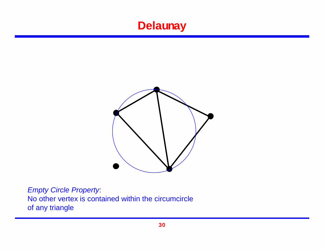
Delaunay
Empty Circle Property: No other vertex is contained within the circumcircleof any triangle

31
Delaunay

32
Delaunay
Empty Circle Property: No other vertex is contained within the circumcircleof any triangle

33
Delaunay
Empty Circle Property: No other vertex is contained within the circumcircleof any triangle

34
Delaunay
35
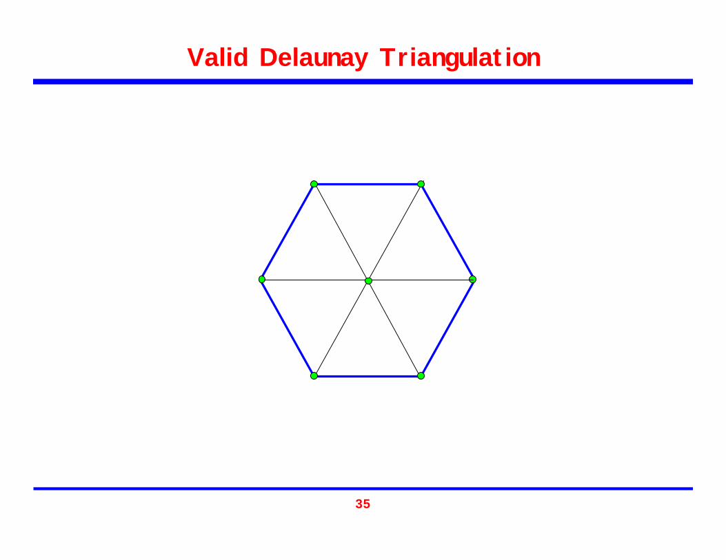
Valid Delaunay Triangulation
36
Valid Delaunay Triangulation
37
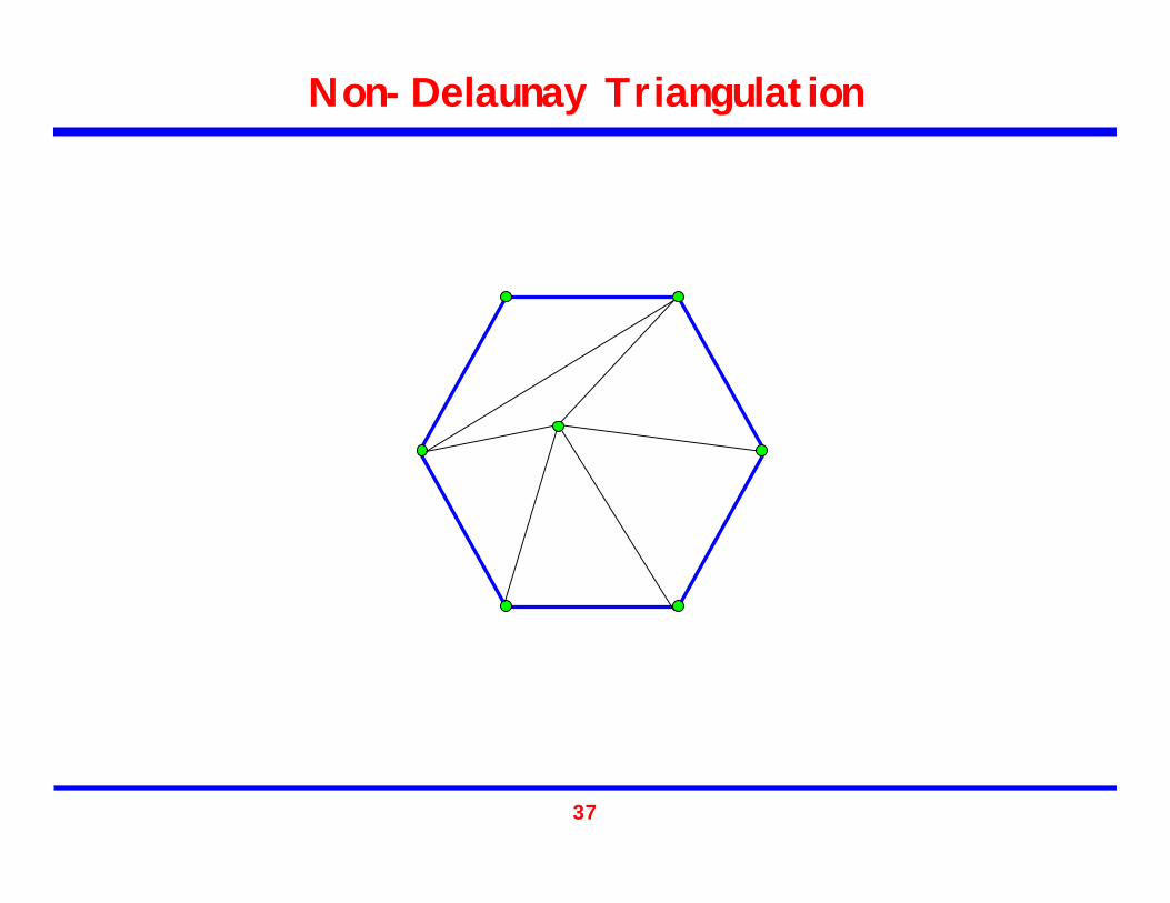
Non-Delaunay Triangulation

38
Non-Delaunay Triangulation

39
Delaunay – Node Insertion
Want to insert one node
40
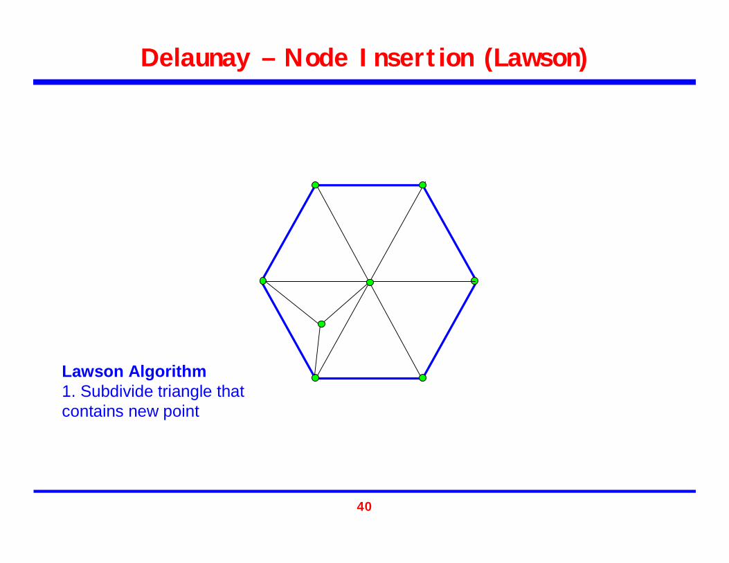
Delaunay – Node Insertion (Lawson)
Lawson Algorithm1. Subdivide triangle that contains new point

41
Delaunay – Node Insertion (Lawson)
Lawson Algorithm2. Empty circle check for new and surrounding triangles

42
Delaunay – Node Insertion (Lawson)
Lawson Algorithm3. Move diagonal if necessary and recheck

43
Delaunay – Node Insertion
Want to insert one node

44
Delaunay – Node Insertion (Bowyer-Watson)
Bowyer-Watson Algorithm1. Find all triangles whose circumcircle contains the new node.
45
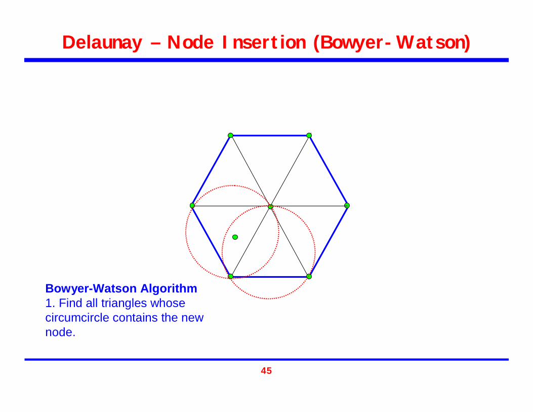
Delaunay – Node Insertion (Bowyer-Watson)
Bowyer-Watson Algorithm1. Find all triangles whose circumcircle contains the new node.
46
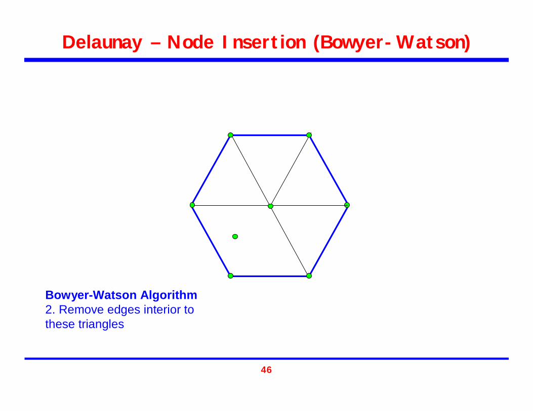
Delaunay – Node Insertion (Bowyer-Watson)
Bowyer-Watson Algorithm2. Remove edges interior to these triangles

47
Delaunay – Node Insertion (Bowyer-Watson)
Bowyer-Watson Algorithm3. Connect nodes of this empty space to new node.
48
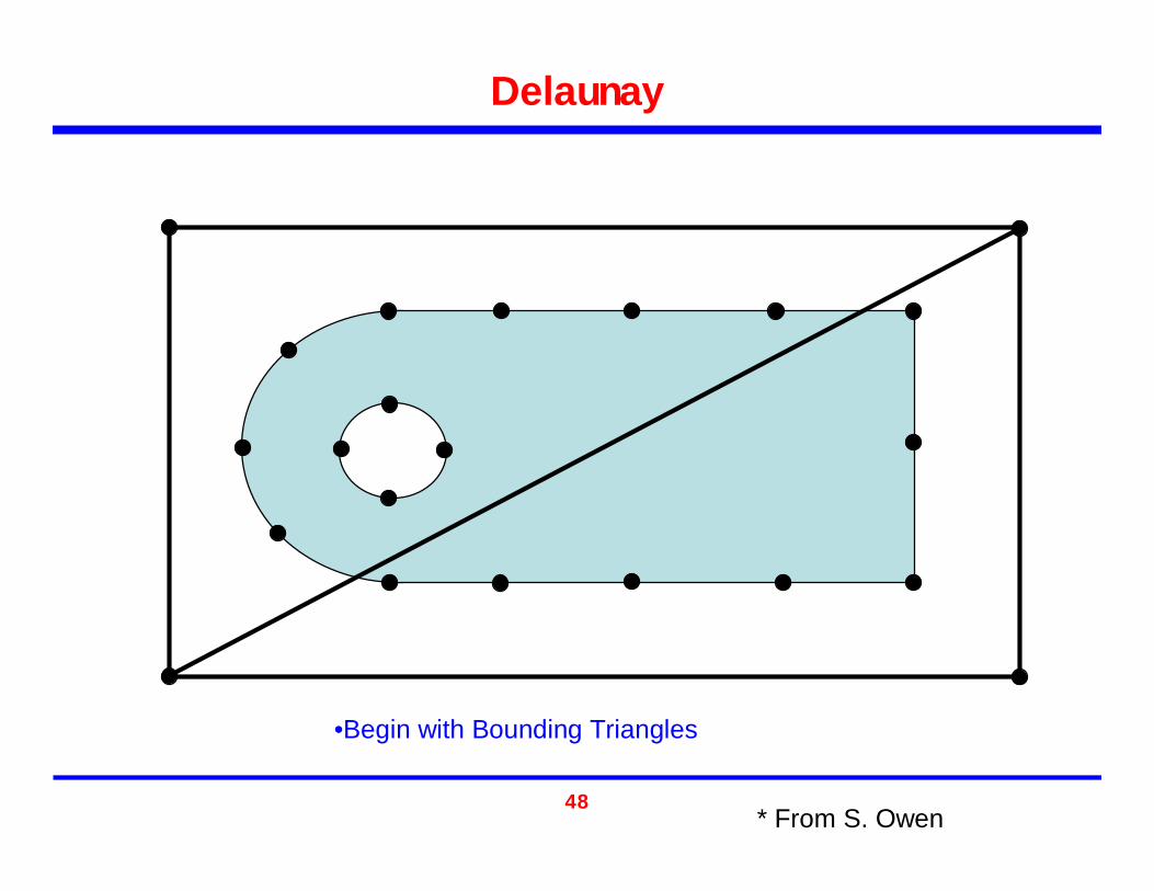
•Begin with Bounding Triangles
Delaunay
* From S. Owen

49
Delaunay
•Insert boundary nodes using Delaunay method (Lawson or Bowyer-Watson)

50
Delaunay
•Insert boundary nodes using Delaunay method (Lawson or Bowyer-Watson)
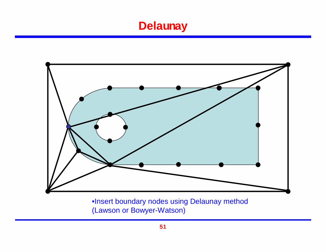
51
Delaunay
•Insert boundary nodes using Delaunay method (Lawson or Bowyer-Watson)

52
Delaunay
•Insert boundary nodes using Delaunay method (Lawson or Bowyer-Watson)
53
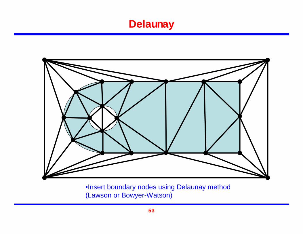
Delaunay
•Insert boundary nodes using Delaunay method (Lawson or Bowyer-Watson)
54
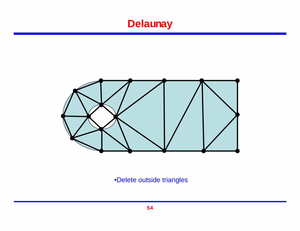
Delaunay
•Delete outside triangles

55
Delaunay – Interior Nodes
Grid Based•Nodes introduced based on a regular lattice
h

56
Grid Based•Nodes introduced based on a regular lattice
Delaunay – Interior Nodes

57
Delaunay – Interior Nodes
Centroid•Nodes introduced at triangle centroids•Continues until edge length, hl ≈
58
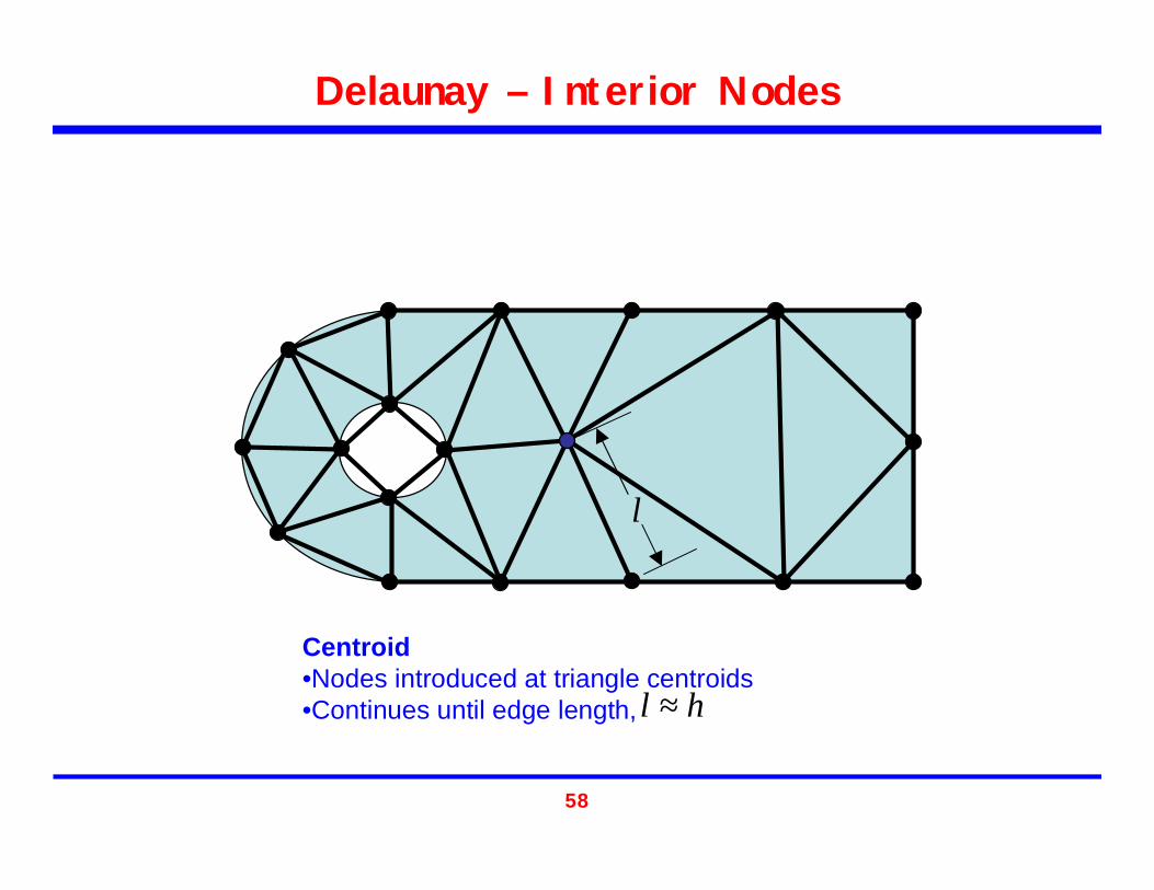
Delaunay – Interior Nodes
Centroid•Nodes introduced at triangle centroids•Continues until edge length, hl ≈
l
59
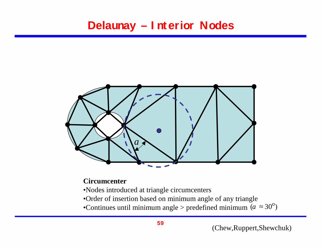
Delaunay – Interior Nodes
Circumcenter•Nodes introduced at triangle circumcenters•Order of insertion based on minimum angle of any triangle•Continues until minimum angle > predefined minimum
α
)30( o≈α
(Chew,Ruppert,Shewchuk)

60
Delaunay – Interior Nodes
Circumcenter (“Guaranteed Quality”)•Nodes introduced at triangle circumcenters•Order of insertion based on minimum angle of any triangle•Continues until minimum angle > predefined minimum )30( o≈α
(Chew,Ruppert,Shewchuk)
61
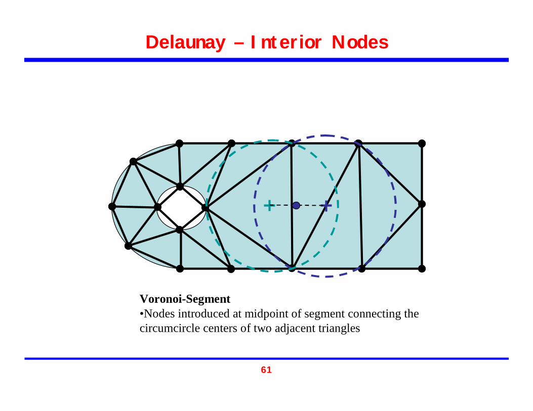
Delaunay – Interior Nodes
Voronoi-Segment•Nodes introduced at midpoint of segment connecting the circumcircle centers of two adjacent triangles
62
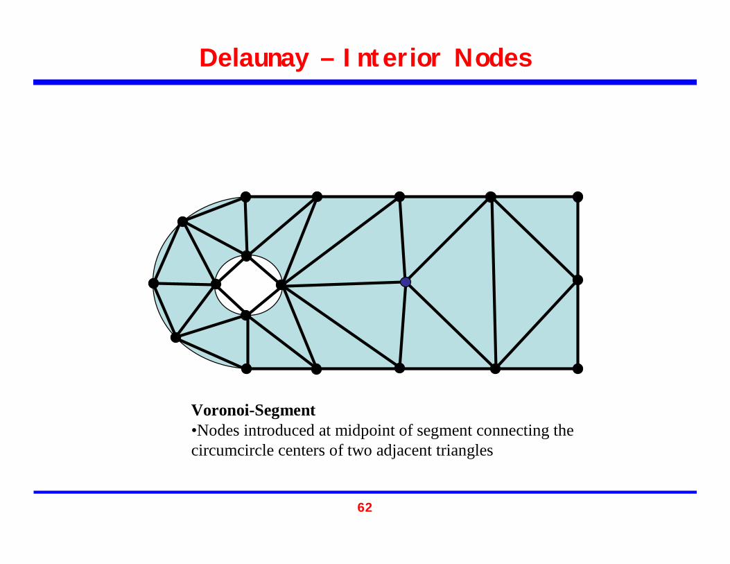
Delaunay – Interior Nodes
Voronoi-Segment•Nodes introduced at midpoint of segment connecting the circumcircle centers of two adjacent triangles

63
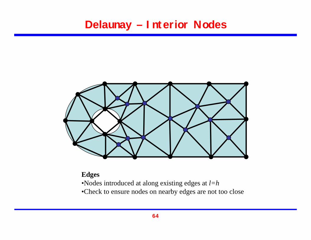
Delaunay – Interior Nodes
Edges•Nodes introduced at along existing edges at l=h•Check to ensure nodes on nearby edges are not too close
h
h
h
64
Delaunay – Interior Nodes
Edges•Nodes introduced at along existing edges at l=h•Check to ensure nodes on nearby edges are not too close

65
Delaunay – Constrained Boundaries
Boundary Intersection•Nodes and edges introduced where Delaunay edges intersect boundary
* From S. Owen
66
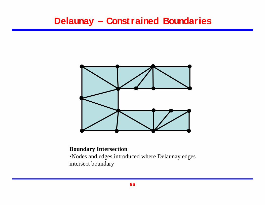
Delaunay – Constrained Boundaries
Boundary Intersection•Nodes and edges introduced where Delaunay edges intersect boundary
67
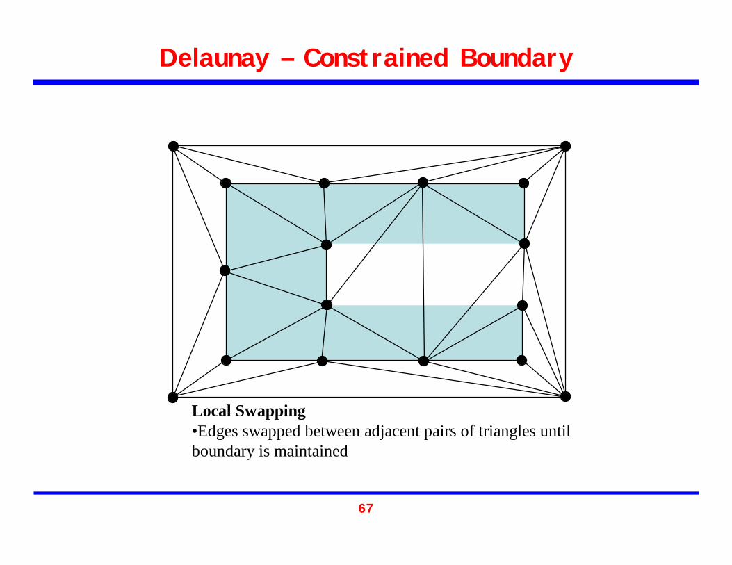
Delaunay – Constrained Boundary
Local Swapping•Edges swapped between adjacent pairs of triangles until boundary is maintained
68
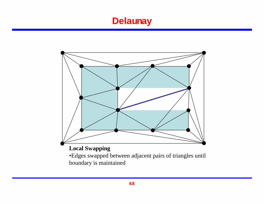
Delaunay
Local Swapping•Edges swapped between adjacent pairs of triangles until boundary is maintained

69
Delaunay – Constrained Boundary
Local Swapping•Edges swapped between adjacent pairs of triangles until boundary is maintained

70
Delaunay – Constrained Boundary
Local Swapping•Edges swapped between adjacent pairs of triangles until boundary is maintained
71
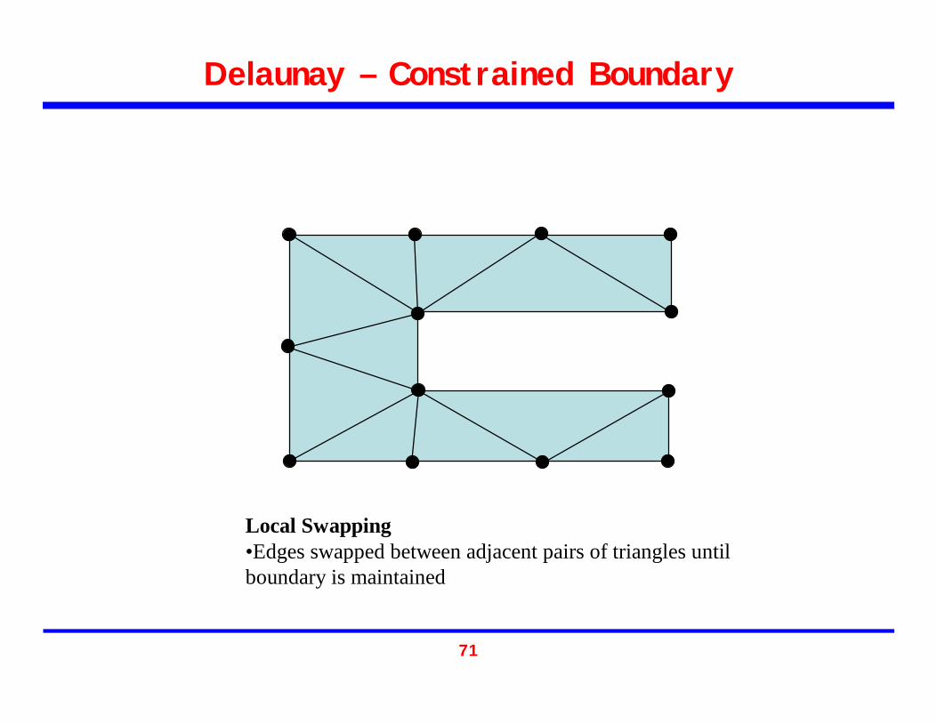
Delaunay – Constrained Boundary
Local Swapping•Edges swapped between adjacent pairs of triangles until boundary is maintained

72
Overview
• Introduction to Mesh Generation• Mesh Quality• Serial Meshing Methods
– Quadtree/Octree– Advancing Front – Delaunay
• Parallel Mesh Generation– Why Parallel?– Categorization Parallel methods– Subdomains, interfaces, separators
• CSAR Mesh Repair in Rocket Simulation
73
Parallel Mesh Generation
• Why Parallel?– Meshes require too much memory to generate
serially– Mesh generation becomes computational
bottleneck in simulation– Already have parallel simulation and need to
remesh/repair/refine

74
Categorization of Parallel Mesh Generation
• Nikos Chrisochoides in [1] advocated the use of “off-the-shelf” serial mesh generators to develop parallel mesh generator.
• Using this idea parallel mesh generators can be categorized by:– Underlying sequential mesh generation algorithm– Parallel Coupling

75
Categorization of Parallel Mesh Generation
• Underlying sequential mesh generation algorithm– Octree– Delaunay– Etc.
• Parallel Coupling– Process interface meshed before subproblems
meshed– Subproblems meshed and then process interface
meshed– Process interface and subproblems simultaneously
meshed

76
Interface/Artificial Boundary
• Process Boundaries must be well chosen– Load must be balanced– Process boundaries should be well spaced– Process boundaries should not form small angle with other
process boundaries or physical boundaries• Usually not a problem if mesh partitioner is
reasonable• Constrained optimization• Changing domains can pose a problem

77
Overview
• Introduction to Mesh Generation• Mesh Quality• Serial Meshing Methods
– Quadtree/Octree– Advancing Front – Delaunay
• Parallel Mesh Generation– Why Parallel?– Categorization Parallel methods– Subdomains, interfaces, separators
• CSAR Mesh Repair in Rocket Simulation

78
Mesh Repair in Rocket Simulation
• Independent Study with Professor Heath and Damrong Guoy
• Want to improve mesh quality of adaptively refined mesh in rocket simulation
• Center for the Simulation of Advanced Rockets (CSAR)
• Terry Wilmarth and Phil Alexander also working on aspects of this project

79
Evolving Geometry of Rocket
• Shrinking solid propellant• Expanding gas flow• Deforming due to high pressure• Crack propagation
Courtesy of Damrong Guoy, CSAR

80
Evolving Geometry
• http://www.cse.uiuc.edu/~jiao/Rocprop/movies/starslice_entropy.mpg• http://www.cse.uiuc.edu/~jiao/Rocprop/results.html
Courtesy of Jim Jiao(via Damrong Guoy), CSAR

81
Poor Quality Elements
• Elements are distorted as a result of the changing geometry
• Elements in expanding region are stretched
• Elements in compressed region are flattened
82
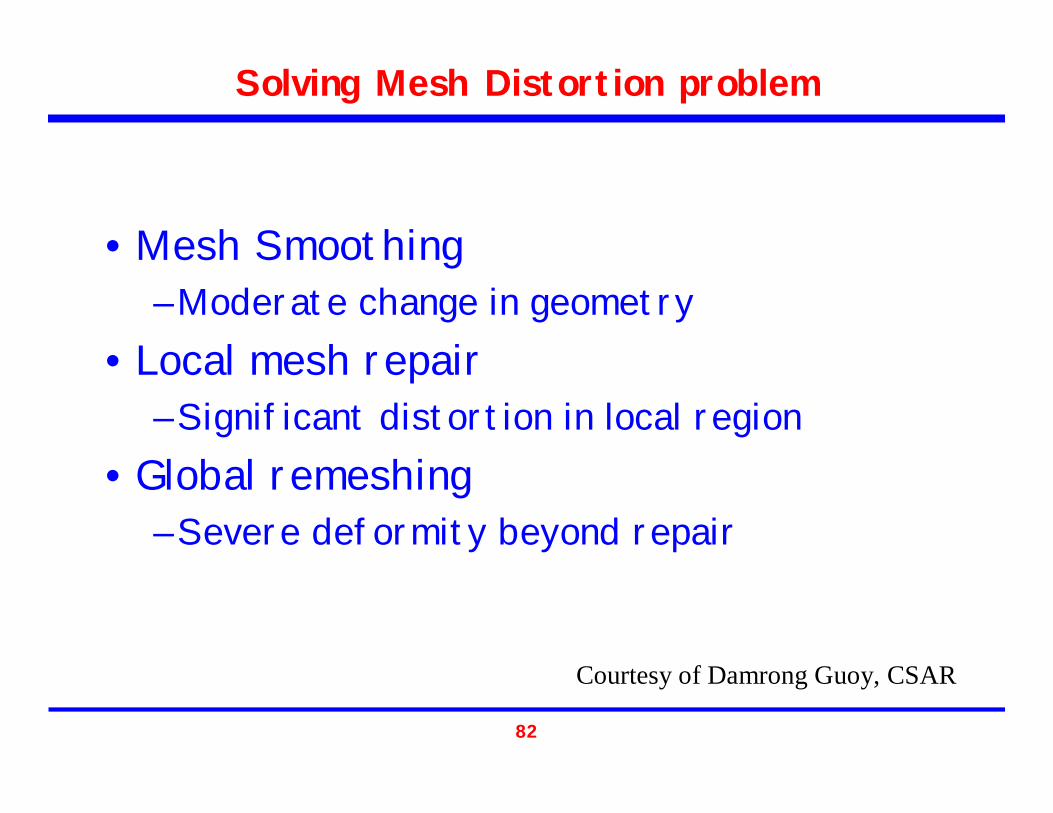
Solving Mesh Distortion problem
• Mesh Smoothing– Moderate change in geometry
• Local mesh repair– Significant distortion in local region
• Global remeshing– Severe deformity beyond repair
Courtesy of Damrong Guoy, CSAR

83
Local Mesh Repair
• Repair local distortion• Preserve large part of the mesh• Locally refine and coarsen the mesh• Many basic operations
Courtesy of Damrong Guoy, CSAR

84
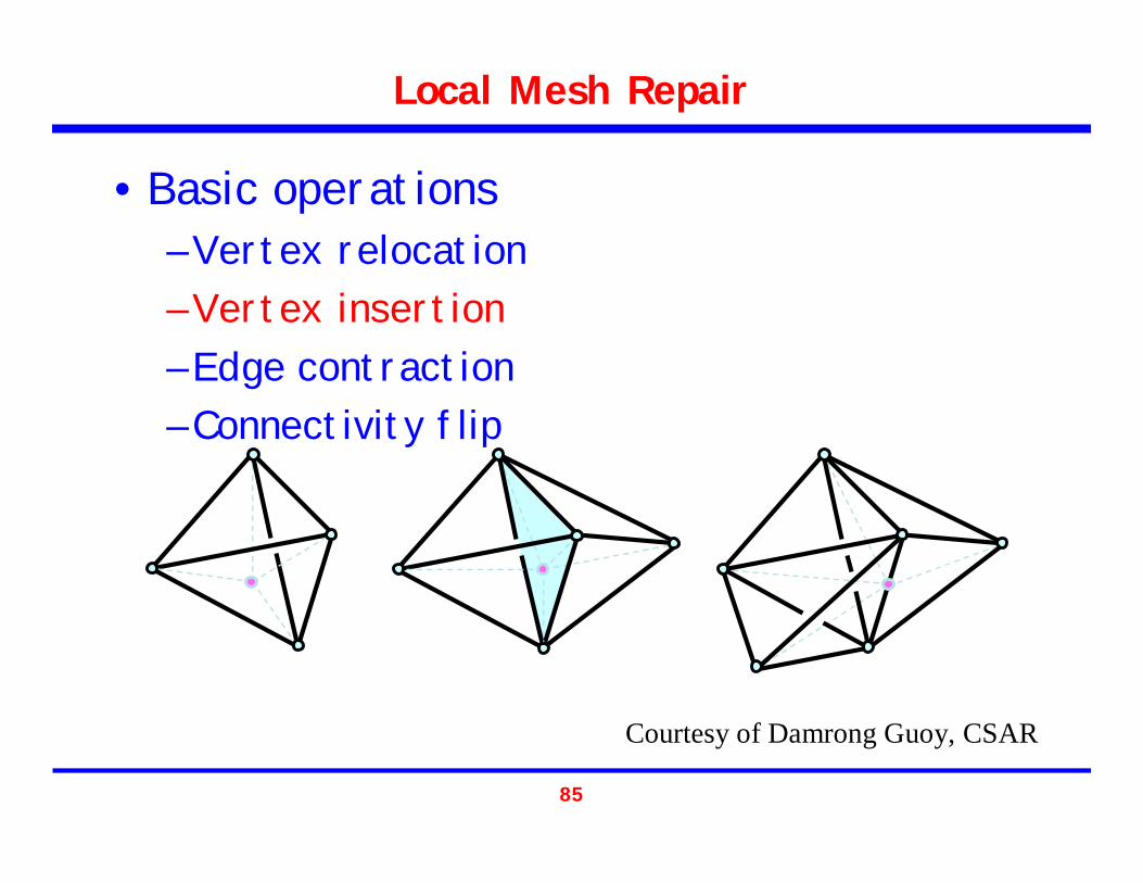
Local Mesh Repair
• Basic operations– Vertex relocation– Vertex insertion– Edge contraction– Connectivity flip
Courtesy of Damrong Guoy, CSAR
85
Local Mesh Repair
Courtesy of Damrong Guoy, CSAR
• Basic operations– Vertex relocation– Vertex insertion– Edge contraction– Connectivity flip
86
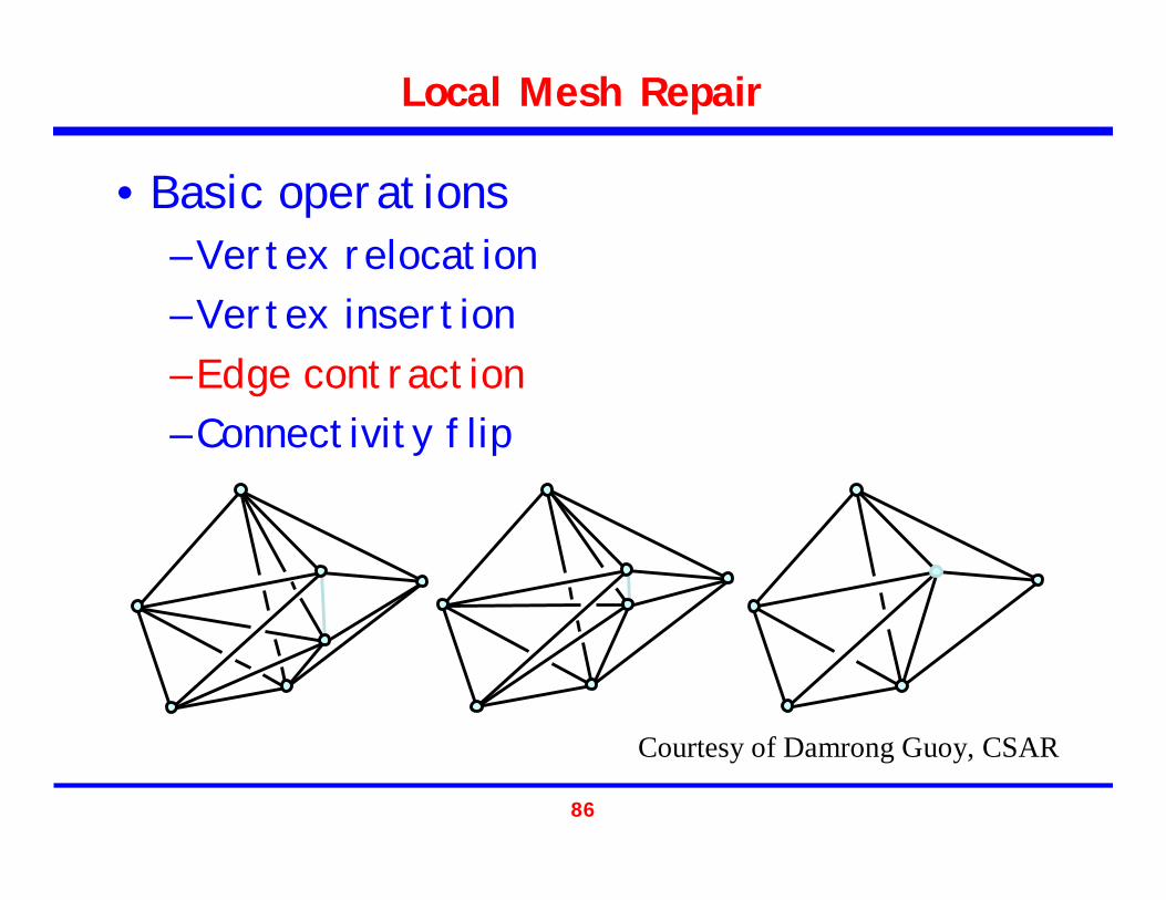
Local Mesh Repair
Courtesy of Damrong Guoy, CSAR
• Basic operations– Vertex relocation– Vertex insertion– Edge contraction– Connectivity flip

87
Local Mesh Repair
2 tetrahedra 3 tetrahedra 3 tetrahedra 2 tetrahedra
Courtesy of Damrong Guoy, CSAR
• Basic operations– Vertex relocation– Vertex insertion– Edge contraction– Connectivity flip
88
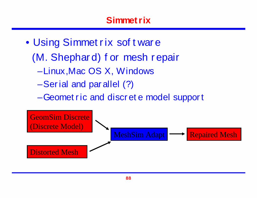
Simmetrix
• Using Simmetrix software (M. Shephard) for mesh repair
– Linux,Mac OS X, Windows– Serial and parallel (?)– Geometric and discrete model support
Distorted Mesh
GeomSim Discrete(Discrete Model)
MeshSim Adapt Repaired Mesh
89
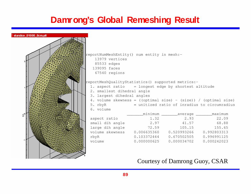
Damrong’s Global Remeshing Result
reportNumMeshEntity() num entity in mesh:-13979 vertices85533 edges
139095 faces67540 regions
reportMeshQualityStatistics() supported metrics:-1. aspect ratio = longest edge by shortest altitude2. smallest dihedral angle3. largest dihedral angles4. volume skewness = ((optimal size) - (size)) / (optimal size) 5. rbyR = unitized ratio of inradius to circumradius6. volume
_______minimum _______average _______maximumaspect ratio 1.32 2.93 22.09small dih angle 2.97 41.57 68.88large dih angle 72.59 105.15 155.65volume skewness 0.006635360 0.520993266 0.992803313rbyR 0.103372444 0.670502505 0.996991125volume 0.000000625 0.000034702 0.000242023
Courtesy of Damrong Guoy, CSAR

90
Before Mesh Repair
reportNumMeshEntity() num entity in mesh:-143389 vertices935693 edges
1560104 faces767799 regions
reportMeshQualityStatistics() supported metrics:-1. aspect ratio = longest edge by shortest altitude2. smallest dihedral angle (degree)3. largest dihedral angles (degree)4. volume skewness = ((optimal size) - (size)) / (optimal size) 5. rbyR = unitized ratio of inradius to circumradius6. volume
minimum average maximumaspect ratio 1.24 4.56 169.83small dih angle 0.71 34.87 69.77large dih angle 71.08 116.54 178.36volume skewness 0.000208097 0.707317863 0.999999960rbyR 0.000517771 0.490753236 0.999882321volume 0.000000044 0.000003054 0.000028641

91
After Mesh Repair
reportNumMeshEntity() num entity in mesh:-39211 vertices
219771 edges336631 faces156070 regions
reportMeshQualityStatistics() supported metrics:-1. aspect ratio = longest edge by shortest altitude2. smallest dihedral angle (degree)3. largest dihedral angles (degree)4. volume skewness = ((optimal size) - (size)) / (optimal size) 5. rbyR = unitized ratio of inradius to circumradius6. volume
minimum average maximumaspect ratio 1.29 3.28 29.84small dih angle 2.50 38.90 69.07large dih angle 72.34 108.67 173.16volume skewness 0.004655401 0.550685298 0.999879335rbyR 0.014748121 0.631093733 0.997732522volume 0.000000214 0.000015025 0.000096563

92
Future Work (near future)
• Better improvement of mesh quality– Learn how to use Symmetrix better– More iterative mesh-repairing strategy
• Parallel mesh-repair

93
Acknowledgements
[1] L. Paul Chew, Nikos Chrisochoides, and Florian Sukup. “Parallel Constrained Delaunay Meshing,” In the proceedings of 1997 ASME/ASCE/SES summer meeting, Special Symposium on Trends in Unstructured Mesh Generation, pp 89-96, June 29 - July 2, 1997, Northwestern University, Evanston, IL.
[2] Nikos Chrisochoides. “A Survey of Parallel Mesh Generation Methods,” BrownSC-2005-09.
[3] Damrong Guoy. “Tools and Techniques for Mesh Repair in Rocket Simulation” CSAR seminar. March 30, 2005.
[4] Steve Owen. “An Introduction to Unstructured Mesh Generation.” Mesh Generation and Simulation: A Short Course. USNCCM’03 http://www.andrew.cmu.edu/user/sowen/usnccm03/short_course.html