mice status report september 2010 -...
TRANSCRIPT

MICE STATUS REPORT September 2010 MICE-NOTE-GEN-31616 september 2010
Alain Blondel, Gail Hanson eds.
MICE STATUS REPORT September 2010....................................................................................1Overview.....................................................................................................................................2
MICE Collaboration and Management....................................................................................4MICE Technical Project Management.....................................................................................8MICE operations...................................................................................................................10Approval status of MICE.......................................................................................................11
Step I........................................................................................................................................12Data taking and results.........................................................................................................12Target....................................................................................................................................19TOF detectors.......................................................................................................................21The MICE computing............................................................................................................23
Steps II&III................................................................................................................................25Trackers................................................................................................................................25TOF2.....................................................................................................................................26KL calorimeter.......................................................................................................................26Solid absorbers.....................................................................................................................27The Luminosity Monitor.........................................................................................................28The magnetic shielding plates...............................................................................................30The EMR...............................................................................................................................30The diffuser...........................................................................................................................31MICE Spectrometer Solenoids..............................................................................................33Infrastructure.........................................................................................................................36
Step IV......................................................................................................................................41Focus Coil Magnet................................................................................................................41Hydrogen absorbers..............................................................................................................43Absorber Windows................................................................................................................45Hydrogen storage system.....................................................................................................46Wedge absorber and possible 6D cooling measurement.....................................................49
Steps V& VI..............................................................................................................................54RF cavities............................................................................................................................54RF power system and distribution.........................................................................................57Coupling coil..........................................................................................................................58RF Shields.............................................................................................................................59
References...............................................................................................................................61

OverviewThis report is prepared for the MICE Project Board meeting of September 2010. It constitutes an update of the reports produced for the MICE Funding Agency Committee in December 20081, October 20092 and April 20103 and concentrates on the progress made since. The design of the MICE experiment can be found in the MICE proposal4.
MICE5 is one of the key R&D experiments aimed towards the realization of a Neutrino Factory or Muon Collider. The relevance of these muon machines on the particle physics landscape has been considerably reinforced in the last few years. The Neutrino Factory and Muon Collider are considered as options for the future of Fermilab, as highlighted by the recent creation of the Muon Accelerator Program (MAP), joining forces from the Neutrino Factory and Muon Collider Collaboration6 with the Muon Collider Task Force7. The MAP8 budget proposal to DOE foresees two relevant milestones: the completion of the MICE US hardware commitments by US FY 2013, and the preparation of a 6D cooling proposal by 2016. The importance of the MICE experiment in this program was highlighted in the recent MAP review9 by DOE. In Europe, the neutrino physics landscape was assessed at the request of CERN council by a panel of the scientific policy committee10 stressing the uniqueness of the Neutrino Factory and the importance of completing the key R&D experiments such as MICE. The Neutrino Factory International Design Study (IDS-NF) has undertaken to evaluate the cost and performance of the Neutrino Factory, with support of the MAP in the US and of the EUROnu FP7 Design Study in Europe; the aim of IDS-NF is to produce an IDR (intermediate design report) in 2011 and a RDR (Reference Design Report) in 2012/13, a date for which having results from MICE is of great importance.
We are happy to report the recent approval of a grant from NSF to a consortium of US universities led by University of Riverside, and the positive outcome of an MRI grant proposal by University of Mississippi for provision of RF hardware.. We are also happy to welcome the group of Prof. Young-Kee Kim and collaborators (University of Chicago, Enrico Fermi Institute) who joined MICE in March 2010.
The MICE experimental program is designed to be achieved in steps, driven both by the scientific methodology and the need to stage resources. The schedule was reviewed at a recent collaboration meeting in UC Riverside 24-28 March 201011. The schedule synopsis is shown in Figure 1. We are presently proceeding successfully through step I while progressing in the preparation for the following ones. A summary of the progress in each step is given in the following sections. Step I is now fully complete from the hardware point of view. The highlight of this report is certainly the successful data taking that took place in the ISIS cycle 2010/02 from 7 June to 15 August 2010. More than 13 million particle triggers were recorded in MICE, allowing investigation and optimization of the muon beam rate, alignment and matching for all 9 combinations of momentum and emittance that will be used for the following steps.
The schedule for the following steps is driven by the delivery of the large components, mainly the superconducting magnets. The difficulties encountered on the spectrometer solenoid magnets have delayed steps II and III by almost one full year with respect to the schedule presented in October 2009 Figure 2. The mechanical construction of both magnets is complete but, while one magnet (“Magnet 2”) has been cooled successfully and excited to currents very close to the
2

operational values, one of its High Temperature Superconducting (HTS) leads was burned during a power-up in summer 2009. An extensive review took place in November 2009 and approved the proposal by the LBNL team to add one more cryocooler. The review also recommended completion of the thermal model of the magnet, inclusion of further diagnostics and extensive thermal measurements. At the next series of powering trials in March 2010, an open circuit developed in one of the five coils (the central matching coil) in the area of the of low temperature leads. In addition the magnet exhibited large Helium consumption indicating abnormally high thermal losses at low temperature. These incidents point to the fact that the design chosen for the MICE magnet cryogenics, with individual cryocoolers, requires near perfection in both thermal design and execution. The situation was taken very seriously at a high level of management at both Berkeley and Fermilab. An extensive review was conducted by Fermilab magnet experts in May 2010, with conclusions published two month later. The magnet was open and in August 2010 it was found that the cold lead was burned in the vicinity of the cold feed-through, in a short region where the superconductor was not protected. After consideration of alternatives, the more practical option is to repair the magnets at the vendor with intense supervision from MICE personnel. The situation thus requires an important increase of qualified manpower and we can report that the LBNL team in charge of the magnets has been considerably reinforced. A detailed repair plan is being established and will be reviewed in the first half of October. Since the other magnets in MICE (focus coils for step IV onwards and coupling coils for step V onwards) share many similarities to the spectrometer solenoids (cooling with cryocoolers in particular) it is crucial to arrive at a good understanding of the problems encountered. Before a complete understanding of the repair plan we prefer not to give an update of the revised schedule.
While the delivery of magnets dominates the schedule (and the risk) for all steps of MICE, other elements of risk exist at all the steps as described in the corresponding chapters, given that no cooling channel has been built before. The succession of steps offers some possibility of time recovery: if opportune, step II could be skipped to go directly to step III, and we are investigating the possibility to jump directly to step IV if the hardware is ready. In addition, part of the setting up of the modules involved in a step can, in principle, be done in parallel to the data taking for the previous step, allowing some of the delay to be absorbed. However one should stress that it will be necessary to understand the physics involved in each step before moving on to the next one. This can only happen if sufficient physicist manpower is available.
3

Figure 1: MICE steps and schedule as of March 2010.
Figure 2: The MICE schedule as of September 2009.
MICE Collaboration and ManagementThe MICE experiment was born in June 2001 of a Memorandum written at NUFACT01 in Tsukuba (Japan) giving mandate to a small kernel (MICE steering group) to assemble a collaboration and put together a proposal by the end of 2002. The MICE LOI was jointly submitted at the end of 2001 to PSI and RAL, and after negotiations between the two labs, it was decided to concentrate on RAL with a contribution from PSI of the decay solenoid. The MICE proposal was submitted to RAL on 10 January 2003, and contained a first distribution of tasks among the collaborators.
The MICE collaboration is run according to the MICE constitution12. The membership of the collaboration was given in the 2009 status report2 2, and is in the process of being updated in view
4

of the first MICE publication. The management chart is given in Figure 3, and a sketch of the hardware responsibilities across the collaboration is given in Figure 4 -- note that the beam line and infrastructure (UK responsibilities) are clearly underrepresented in this sketch. A breakdown across the MICE steps of the tasks necessary to assemble them and the completion status is given in Table 1, Table 2, Table 3, Table 4, Table 5 for step I, II/III, IV, V, and VI respectively.
Figure 3 MICE management organization (not including operations)
Figure 4 MICE collaboration across the planet.
5

Table 1 MICE responsibilities for STEPI. The two color columns indicate the status level in spring 2009 and fall 2010 respectively. Color code: green= ready and operational; yellow: funded and in construction; orange: funded but late or problems/risks involved; red: funded but major technical issues; black: not funded.
MICE STEP IMuon beam line Responsibility 2 dipoles 9 quads, PS, controls RAL, DL Decay solenoid PSI Decay solenoid cryo and PS, RAL Target system Sheffield,
DL,RAL Target in ISIS success!
New targets under construction
Hall infra., shielding, beam stop RAL detectors TOF0 and TOF1 INFN MIB,
INFN PV, GVA
CKOV A,B Mississipi KL calorimeter Roma3 INFN Front end electronics, DAQ, trigger GVA, INFN Control room MICE-UK Software MICE collab. Beam monitors FNAL, GVA Detector cabling and installation RAL, DL
Table 2 MICE responsibilities for STEPII/III/III.1. Color columns indicate the status level in spring 2009 and fall 2010 respectively. Color code: green= ready and operational; yellow: funded and in construction; orange: funded but late or problems/risks involved; red: funded but major technical issues; black: not funded.
MICE STEP II/III/III.1Infrastructure RAL Trackers UK, USA, JP Spectrometer Solenoid I&II LBNL Magnetic measurements at RAL- CERN teamMagnetic probes NIKHEF TOF2 and TOF shielding INFN MIB, INFN
PV
Spool piece GVA Absorbers (LiH…) FNAL Software MICE EMR muon ranger GVA,FNAL,
Trieste/Como prototyped,
under constructionPower sub-station upgrade RAL, DL under procurementSafety equipment RAL, DL PPS Sept 2010
6

Table 3 MICE responsibilities for STEP IV. The two color columns indicate the status level in sprin 2009 and fall 2010 respectively. Color code: green= ready and operational; yellow: funded and in construction; orange: funded but late or problems/risks involved; red: funded but major technical issues; black: not funded.
MICE STEP IVLiquid Hydrogen infrastructure and controls
RAL, DL
Focus coil magnet RAL, Oxford FC Magnetic measurements CERN Liquid hydrogen absorber and instrumentation
KEK
Liquid Hydrogen and safety windows
Mississippi
Software MICE
Table 4 MICE responsibilities for STEP V. The two color columns indicate the status level in sprin 2009 and fall 2010 respectively. Color code: green= ready and operational; yellow: funded and in construction; orange: funded but late or problems/risks involved; red: funded but major technical issues; black: not funded.
MICE STEP VRF in Mag fied R&D MUCOOL
NFMCC/MAPdelayed by CC-0
RF cavities (1+4) LBNL 2 Coupling coils (MUCOOL+ MICE CCI)
ICST-HIT, LBNL
CCI Magnetic measurements CERN RF Power sources parts 4+4MW CERN, LBNL RF refurbishment 4+4 MW CERN, DL RF refurbishment 4+4 MWRF infrastructure for 4 cavities
CERN, DLDL, RAL
Liquid Hydrogen infrastructure (II) RAL Focus coil magnet II RAL, Oxford FC Magnetic measurements UK Liquid hydrogen absorber II KEK Liquid Hydrogen and safety windows II
Mississippi
RF Shield Fermilab construction at FNAL
Software, controls MICE (needs to design controls of cooling channel)
Table 5 MICE responsibilities for STEPI. The two color columns indicate the status level in sprin 2009 and fall 2010 respectively. Color code: green= ready and operational; yellow: funded and in construction; orange: funded but late or problems/risks involved; red: funded but major technical issues; black: not funded.
7

MICE STEP VIRF cavities (4) LBNL Coupling coil (MICE CCII) ICST-HIT,
LBNL
CCII Magnetic measurements FNAL/CERN RF infrastructure for 4 cavities DL, RAL
Liquid Hydrogen infrastructure (III) RAL Focus coil magnet III RAL, Oxford
FC Magnetic measurements UK Liquid hydrogen absorber III KEK Liquid Hydrogen and safety windows III
Mississippi
Software, controls (needs to design controls of cooling chanel)
MICE Technical Project Management BackgroundAndy Nichols is the MICE Project Manager. He is also the project manager of the MICE-UK project.
It has been long recognized that both the MICE project as a whole and the complex UK project required a strong project-management team. Therefore, the UK members of the MICE collaboration proposed to augment it with an additional engineer. With the support of the MICE UK Oversight Committee, a project planner (Chris Bulloch) was recruited for a fixed 6-month term from a firm of consultants. Chris Bulloch's appointment terminates in October 2010, at which point a permanent STFC employee, Roy Preece, will take over and provide a strong central project management unit for the whole collaboration. Management of the construction projects at the far sites may require intense presence.
The project-planning paradigm was first applied to the UK project and will be extended to the whole MICE project with a first immediate objective, the re-evaluation of the MICE schedule.
DutiesOver the past two years, the UK deliverables and infrastructure have been put in place to serve MICE Steps I to III. Work is now in hand to deliver the infrastructure required for steps IV and V.
The next task now is to organise the major MICE subsystems, such as the spectrometer solenoids, the focus coils, and the coupling magnets, that are being contributed to MICE so that a realistic and above all credible top-level experimental schedule can be constructed. It is clear that the Project Manager (Technical Coordinator) needs to work more closely with the international collaborators to help them reinforce, when needed, rigorous engineering discipline and quality
8

assurance methodology across the whole project. This approach has been applied successfully on two previously problematic UK activities, the target and the experimental infrastructure.
Organisational methodsThe top-level MICE schedule is reviewed at each MICE Collaboration Meeting (CM), using data supplied by the work package owners to the Project Manager. The progress against milestones is reviewed monthly at the Technical board meetings. A new schedule is issued by the executive board if sufficient confidence exists. On exceptional cases a new schedule may be issued at other occasions than a collaboration meeting.
At a more detailed level, and using the UK project as an example, a weekly cost and schedule meeting is held between all UK WP managers, at which the project Gannt charts are reviewed, spend against allocation is reviewed, and control measures are implemented – this is against the background of ever more stringent financial constraints on the UK.
Technical matters are reported to the MICE Technical Board, which is chaired by the Project Manager and meets monthly. As the project moves to a more intense installation period, the emphasis will shift to mechanical and electrical integration and technical compatibility. Short time scale activities are planned and tracked by the MICE Hall planning meeting, chaired by the Principal Contractor, and at the MICE Installation and Commissioning (MICO) meeting, chaired by the Project Manager; both of these meetings are held weekly.
A project risk register for the UK activity has also been generated and is reviewed monthly. It can be found at: http://mice.iit.edu/tb/MICE-WBS-Schedule/
WBSThe top-level MICE Work Breakdown Schedule can be found at:http://mice.iit.edu/tb/MICE-WBS-Schedule/
MICE SafetyThe MICE experiment is being hosted by STFC at its ISIS facility. The project and its staff have to comply with the following mandatory safety frameworks:
Construction Design & Maintenance (CDM) regulations STFC Safety Health and Environment (SHE) regulations Ionising Radiation Regulations 1999 (IRR)
Safety matters are included as a standing agenda item in the monthly Technical Board meetings and the Project Manager and MOM report to each formal MICE-ISIS Safety meeting, which is held every three months.
The MICE Project Manager retains ultimate responsibility for project safety.
CDM regulations
9

All civil engineering projects in the UK must comply with the above rules, which set out to define the safety responsibilities of both the host and the user. The CDM framework is supervised by a Principal Contractor (PC). He is Willie Spensley and is the first point of technical contact for MICE users. He will organise a formal induction course for the user and enforce the obligatory processes and wearing of Personal Protective Equipment (PPE). MICE is in the position of being a running physics experiment as well as a construction site, which is unusual, but no real problems have arisen after a long period of running like this.
SHE regulationsThis covers the normal issues of domestic fire safety and normal everyday hazards and evacuation procedures. It is also enforced by the Principal Contractor and all MICE visitors must attend a relevant safety course before participating in the experiment
IRR 1999The IIR regulations are primarily addressed by the MICE Personal Protection System (PPS), which is a series of electro-mechanical interlocks and procedures that form the fundamental barrier between the ISIS synchrotron and the MICE users. The PPS is due to be implemented in October 2010 and up to that point all running has been done with ISIS approval under a system of manually locked gates, which is described by an Operational Procedure Note (OPN).
As MICE evolves, other hazards, such as RF, hydrogen and lithium hydride will present themselves. These will have to interact with the PPS at some level, but suitable adaptability has been designed into the system.
A requirement of the IIR is that a Radiation Protection Supervisor (RPS) and a deputy be appointed. These are respectively Tim Hayler and Matt Hills.
MICE operationsIt is a characteristic of MICE that installation, commissioning and data taking are interleaved in the MICE Hall. This requires dedicated organization of the day-to-day activities. Day-to-day MICE Operations are overseen on a one-month rotation basis by the MICE Operations Manager (MOM), an experienced member of the collaboration chosen by the spokesperson in agreement with the MICE project manager and the ISIS director. The MOM has delegation from the spokesperson for the execution of the physics program and from the Project Manager in matters of safety. The operations are coordinated in a weekly meeting (MICO for MICE Installation, Commissioning and Operations) chaired by the project manager with the MOM as secretary. The MOM is assisted by an ISIS contact (C. Rogers, RAL) and the BLOC (beam Line On-Call expert, on rotation). Each component of MICE relevant to Installation Commissioning or Operations has an on-call person responsible. For each series of experiments (project) to be performed a physicist on charge follows the preparation, data taking plan, data taking, analysis and publication. Marco Apollonio (Imperial) plays this role for the beam line commissioning that took place in 2010, but other projects took place at the same time such as installation, commissioning, calibration of the various detectors. The MOM coordinates the requests coming from the various projects.
10

For the running of the experiment on ISIS at least two persons are required in the MICE control room. This presence is assured by shifters from the various MICE institutions. Taking shift is part of the duties of the collaboration members. Authorization to run on ISIS has to be requested one week in advance by submission of a run plan prepared by the MOM and interested parties in agreement with the spokesperson.
The MOM scheme has been extremely successful in assuring constant presence on site of members of the collaboration across its geographical diversity. It is extremely demanding of the MOM who has to be present on call 24/7 on site for a month at a time.
The software activities are coordinated by the software coordinator (M. Ellis until 17 September 2010 will be replaced by David Collins from Imperial), while the control room activities are coordinated by the MICE Online Group (MOG, chaired by Jean-Sebastein Graulich from GVA) (see the software section). The data taken are immediately processed in an online reconstruction program (resp. Linda Coney) which provides the shifters with information needed to verify the data quality and make decisions on how to carry out the next steps of the experimental program. Physics data and online control data are transferred to the ATLAS computing center at RAL from where they can be accessed via the GRID by the entire collaboration for off-line processing and analysis.
Approval status of MICE Scientific approval for MICE was granted by STFC in October 2003 following a detailed review of the MICE collaboration's proposal by an international panel chaired by A. Astbury (Victoria). Resources for the UK contributions to Phase I of MICE (the provision of the MICE Muon Beam on ISIS at RAL, and the MICE experiment in the Step II configuration, i.e. including the trackers) were secured in April 2005 through the 'Gateway Process'. (In common with all large, public-sector, capital procurements, the the project was required to follow the Gateway Process in order to access the Large Facilities Fund). In parallel, resources to provide the two Cherenkovs, the tracker, the time-of-flight system and the KL calorimeter, as well as the DAQ system, were secured in the US, Italy, and Switzerland respectively. The spectrometer solenoids, originally proposed to be built in Italy had been taken up by the NFMCC collaboration, under the responsibility of LBNL. In kind contributions for the RF power sources were contributed, in the form of old 200 MHz RF amplifiers from LBNL and CERN – CERN effecting the refurbishment of two 2MW amplifiers and LBNL contributing parts for the assembly of two 2MW amplifiers and three lower level 250 kW amplifiers. A resource plan for MICE, covering the US construction deliverables up to step VI in the US NFMCC was proposed in 2005, subject to the yearly approval of the collaboration resources by DOE.
The resources to discharge the UK responsibilities in Phase II of the project (MICE Steps III to VI) were requested by UK members of the collaboration in 2006. Funds were granted for the period April 2007 to March 2009. At the time this allocation was made it was anticipated that Step V would be implemented by the third quarter of 2009, the scope of the funding was appropriate to deliver MICE to Step V. Subsequently, funding has been made available to MICE-UK on an annual basis to allow the UK to continue to discharge its responsibilities to the collaboration. Further resources to provide scientific manpower to the US project were obtained from the NSF in the US and resources to provide the EMR have been obtained in Switzerland.
11

In July 2009, STFC convened an international panel to carry out a detailed review of the cost and schedule for the completion of the UK contributions to MICE. The cost and schedule documentation presented to the panel included, explicitly, the cost and milestones for the implementation of MICE to step VI. The costs presented to the panel, revised in line with the panel's recommendations, are now used by STFC in planning its financial provision for MICE in the UK.
Recently, J. Womersley confirmed the commitment of STFC to deliver the full MICE project to Step VI. Across the MICE collaboration, resources have been secured to contribute to the delivery of the components required at Step VI and to run the experiment in each of its configurations. Most of the components for MICE to step VI have been now committed among the overseas MICE partners.
Step I
Data taking and results
After a long stop due to the problems connected with the Decay Solenoid, MICE had the chance to run its beam line in a fully operating mode in the ISIS cycle 2010/2 from 7 June 2010 to 15 August 2010. All step I detectors and instrumentations were running: three TOF stations (TOF0, TOF1 and even TOF2), two threshold Cherenkov counters (CKOVa,b), two Beam Profile Monitors (BPM1, BPM2) and a beam intensity counter (GVA1). A Luminosity Monitor was installed at the beginning of the year which allows relative normalization of rates observed with different beam settings on the primary production rate from the target interaction with the beam. Detailed descriptions of detector commissioning and calibrations are given in the relevant paragraphs, while here we focus on the characterization of the beam line.
Measuring Beam properties with TOF0, and TOF1
During the period from June 7th to August 15th 2010, emphasis was given to the characterization of the beam line for the final muon production. We refer to this configuration as a pion-to-muon beam line. With this set up we use the first dipole to select high momentum pions (around 400 MeV/c) while the second dipole is meant to maximize the selection of backward going muons from pion decays (at around 240 MeV/c) and increase the beam purity. Other configurations are used to transmit a single momentum beamline and are generally used for special studies or calibrations.
Beam Line detectors all give information about the beam characteristics and many of them are used to check the beam properties and particle rates on a run-by-run basis. However the TOF stations play a special important role in this data taking campaign, since they can reconstruct single particle tracks. This information is used in a twofold way:
12

a) to monitor the shape and position of the beam (both on-line and offline) and detect particle species as a function of their time of flight differences,
b) to extract the phase space (Twiss) parameters at TOF0 or TOF1 position (also both on-line and off-line).
Other than completing the commissioning and calibration of beam detectors, the main goal of this data taking period was to assess our level of understanding and control of the line. To achieve this an intense campaign of runs at different optics configurations has been launched. The beam line has also been run in two polarities: in negative mode a cleaner sample of muons is produced at expense of intensity. A more efficient beam line is obtained in positive polarity, with the drawback of proton contamination. A proton absorber made of different polyethylene sheets have been used in order to mitigate this problem with effective results. Figure 5 illustrates the effectiveness of the proton absorber on a positive beam line13.
Figure 5 Time of flight distribution between GVA1 counter and TOF0. (Left) In air, two species of particles are seen. (Right) The addition of a polyethilene layer of 10 cm at the exit of the decay solenoid is effective at eliminating the proton component for a beam momentum of 238 MeV/c (at Dipole 2)
13
F

Figure 6 Stability of Reference Runs beam position and momentum. A: (top) horizontal centre of the beam (red dots and error bars) and beam RMS (red band) versus Run Number. (bottom) beam centre and beam RMS distribution. B: same as (A) for the vertical coordinate. C: (top) average momentum versus Run Number (green dots and error bars) and RMS (green band) vertical (right) coordinates at TOF1. The graphs on the top show the beam centre (mean) and its error (small error bars) as a function of the run number. The colored band show the measured RMS of the beam. The bottom plots show the distributions for <x> (RMS_x) and <y> (RMS_y) of the beam for the analysed sample.
The pre-condition for such studies is a stable and calibrated system, which was achieved prior to the actual data taking. In order to monitor this stability, a reference run corresponding to the (6,200) optics, was produced every day. DAQ was vey stable during all the data taking period. Data Quality Check routines were used to verify possible variations over time. Figure 6 shows an example of stability checks over a series of runs. The average position (with its error) and the typical RMS of the beam at TOF1 are monitored. We notice how x position is systematically off- centered with two main populations at 2.5 and 3 cm. Few runs seem to correspond to a negative displacement, which needs further investigation. Vertical position seems to be stably off-centered by 2 cm, however a survey of the TOF1 station in the MICE hall revealed a vertical displacement of the device with respect to the beam line axis compatible with the observed effect. Reconstructed momenta are also monitored and show good stability over a month and a half period.
Another parameter used to verify the stability of our set-up is the time of flight for electrons (positrons) between two TOF stations (typically TOF0 and 1). This kind of check is also nearly independent on the optics, since electrons are always totally relativistic. A summary of this monitoring is shown in Figure 7.
14

Figure 7 Electron Peak monitoring. (left) time TOF0-TOF1 time of flight (ns) showing two particle species (electrons and muons). The electron peak is fitted to a Gaussian. Results for a sequence of runs are displayed (right) showing a good stability around 25.5 ns. The bars represent the error on the average Dt. Apart from few low statistics cases, most of them are of the order of 100 ps
Scan of quadrupoles (both in the downstream and in the upstream section of the beam line) and of the Decay Solenoid have been performed thoroughly in order to understand the response of the system as a function of the optics. Figure 8 shows results obtained during data taken to study the dependence of the beam Twiss parameters from the excitation of the last quadrupole triplet. Phase space for the horizontal and vertical planes at TOF1 position is reconstructed by means of the method outlined before. A comparison with a Monte Carlo simulation in G4Beamline is shown too, showing an encouraging agreement.
Figure 8 Horizontal (left) and Vertical (right) phase space at the upstream face of TOF1 detector as reproduced by the G4Beamline simulation (top) and as reconstructed from real data. Positions in mm are shown on the horizontal axes, transverse component of momentum (in MeV/c) on the vertical axes. This run is one of the scanned Q789 triplets around the nominal value.
15

A summary of the dependance of beam parameters from the excitation of quadrupole triplets are illustrated in Figure 9. We notice a general agreement between data and montecarlo, however some discrepancies still need to be properly understood. In particular for the horizontal coordinate we need to clarify the cause of the shift with respect to the nominal beam axis.
Figure 9 variation of mean position and RMS for the horizontal (blue) and vertical (red) coordinates as recorded at TOF1. G4Beamline simulation is superimposed (black points and error bars).
Adherence between measured data and simulation is important to improve our ability at optimizing the match between the incoming muon beam and the MICE lattice. The MICE program requires the coverage of emittance and momentum within a range of values: N=(3,6,10) mm rad, and P=(140,200,240) MeV/c (at the centre of one hydrogen absorber). The resulting (N,P) matrix can be obtained by means of a lead degrader of variable thickness (the Diffuser) used to inflate the beam emittance in a controlled fashion, and imposes specific optical constraints on the Twiss parameters at the upstream face of the diffuser for each of the 9 matrix elements. Optimization via a Genetic Algorithm (GA)14 and MINUIT [Fletcher] have been produced for some points of the matrix and data for the corresponding optics have been collected. We started from the so called M0 matrix, a simple rescaling in momentum for an initial optics corresponding to the point (6-200). The GA was able to determine solutions for 6 out of the 9 points of the matrix (failing for the points at low emittance), producing the so called M1 configuration. Eventually some tests of a MINUIT optimisation for the sole (6-200) points have been performed (M2 configuration). Figure 10 illustrates the case at (6-200) showing a phase space and momentum reconstruction at TOF1 for the M0 and M1 optimised case.
16

Figure 10 (Top) Reconstructed momentum and Phase Space for the hroizonatl and vertical planes at TOF1, for the M0 (6-200) optics. (Bottom) same as above for the M1 (6-200) optics obtained with the GA optimization.
Beam Rate versus Target Depth
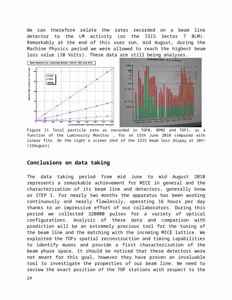
At the beginning and at the end of the user Run we have checked the dependence of the detector rates from the target depth. These kind of studies are essential to extrapolate the number of particles we expect to see when varying the target parameters (depth and time delay w.r.t the ISIS cycle). Figure 11 refers to data taken in the mid of June. Since January we can rely on a Luminosity Monitor (LM) placed inside the ISIS vault (see relevant paragraph). Counts in the LM are linearly correlated to the Beam Losses as recorded by ISIS Sector 7 Beam Loss Monitor. We can therefore relate the rates recorded on a beam line detector to the LM activity (or the ISIS Sector 7 BLM). Remarkably at the end of this user run, mid August, during the Machine Physics period we were allowed to reach the highest beam loss value (10 Volts). These data are still being analyses.
17

Figure 11 Total particle rate as recorded in TOF0, BPM2 and TOF1, as a function of the Luminosity Monitor , for on 15th June 2010 compared with linear fits. On the right a screen shot of the ISIS beam loss dispay at 10V! (15August)
Conclusions on data taking
The data taking period from mid June to mid August 2010 represents a remarkable achievement for MICE in general and the characterization of its beam line and detectors, generally know as STEP I. For nearly two months the apparatus has been working continuously and nearly flawlessly, operating 16 hours per day thanks to an impressive effort of our collaborators. During this period we collected 320000 pulses for a variety of optical configurations. Analysis of these data and comparison with prediction will be an extremely precious tool for the tuning of the beam line and the matching with the incoming MICE lattice. We exploited the TOFs spatial reconstruction and timing capabilities to identify muons and provide a first characterization of the beam phase space. It should be noticed that these detectors were not meant for this goal, however they have proven an invaluable tool to investigate the properties of our beam line. We need to review the exact position of the TOF stations with respect to the beam line in order to understand the effects of misalignment we saw in our data. A better characterization of beam properties and a precise direct measurement of beam phase space and emittance will be possible with a fully equipped spectrometer. During this study we experienced the limitations of a simulation tool (G4Beamline) decoupled from the reconstruction software based on the G4MICE architecture. Extending the G4MICE framework to describe the beamline sector is an important task which will allow a better comprehension of the results obtained so far and an invaluable tool to predict the behaviour of the entire MICE set-up.
18

Target The target installed in ISIS in summer 2009 has been operated regularly to generate particles for the MICE beam throughout the last year. In total, the target experienced 570K dip cycles, in addition to the 50K during tests before installation. Conditions of operation were that the view-port beneath the target should be inspected for dust every 50K actuations, and a “calibration run” should be performed every 10K actuations. For the latter, the target frame was raised and the target operated with a standard dip depth. Photographs of the view-port showed no evidence of dust, and analysis of the calibration runs showed no variation in target behaviour (as had been seen in previous targets when bearing wear was occurring). Figure 12 shows the results of a selection of calibration runs taken throughout the running period.
Figure 12 Target Beam Centre Distance (the distance of closest approach to the beam centre) superimposed from several calibration runs. Note that the rms is about 0.07 mm compared with a target strike of about 44 mm.
Concern over wear with diamond-like carbon coated steel bearings led to the development of Vespel (polyimide) bearings. As described in the previous report, these showed a good lifetime, but a significant amount of fine dust was produced. This is believed to be largely due to poorly polished surfaces on the shaft. However, preliminary measurements of the magnetic axis of the stator used in the tests indicate it is off-set from the mechanical axis of the shaft by about 0.3 mm,
19

and this is likely to have exacerbated the wear. A programme of magnetic measurement is underway to verify this offset, and future bearings will have their aperture displaced to align magnetic and mechanical axes. (Initial measurements were performed using equipment belonging to Diamond. As this is no longer available on the time scale we require, we are setting up to use similar apparatus at Daresbury in the short term, and will develop our own magnetic measurement system at RAL for longer term MICE needs.) In addition, the polishing of all bearing surfaces has been improved, and a mechanical “dust catcher” (illustrated in Figure 13) will be fitted to trap any residual dust.
Figure 13 Dust-catcher can (dark & light blue), around modified shaft (red).
Phase 1 of a new FPGA-based control system has been successfully tested on an old target drive in the assembly hall. This provides a GUI on a PC attached via a USB interface, as a replacement for the hardware switch controls of the present implementation, and also allows better status monitoring. Phase 2 of this development is in progress, with daughter cards to control target hardware under construction. Though Phase 2 will have little direct impact on normal operators, it will allow better diagnostics for experts and is a necessary step towards Phase 3, where the Target DAQ will be integrated into the controller, removing our reliance on third party hardware and closed source software drivers. Discussions have also been held with ISIS over the provision of a Beam Protection System (BPS) signal from the target. This will indicate if the target enters the beam at any time other than the correct ISIS cycle, and also if the target behaviour is diagnosed as being “unusual”. The BPS will require hardware changes at both the target and controller, and specifications will be finalised over the next two months.An outline target
20

schedule covering the next 6 months is presented in Figure 14. This has suffered from delays due to the non-availability of magnetic measurement equipment, as described above. In the longer term, it will be necessary to embark on a programme of coil and magnet improvement, in order both to avoid the problems of magnetic axis misalignment mentioned above and to achieve the higher accelerations required in the future. The scheduling of this work will be undertaken once results from the programme of magnetic measurements are available.
Task CompletionMagnetic measurementsT2#3 refit (with improved alignment, bearingsTarget testsT3 assembly
2 weeks6 weeks3 months
End September 2010Mid October 2010End November 2010End February 2011
Controller Phase 2 and BPS 7 months March 2011Figure 14 Medium-term target schedule.
TOF detectorsAll time-of-flight detectors share a common design based on fast 1” Bicron scintillators along X/Y directions, read each at both ends by fast Hamamatsu R4998 PMTs, providing redundancy and self-calibration with impinging beam particles. They also provide the position of particles with a precision of 1-2 cm. While TOF0 has a fiducial area of 40 x 40 cm2, TOF1 and TOF2 covers a 42 x 42 cm2 and a 60 x 60 cm2 area respectively. The counter width is 4 cm in TOF0 and 6 cm in TOF1 and TOF2. TOF0 and TOF1 were installed in the MICE Hall in the second semester of 2008, while TOF2 was installed in the second semester of 2009. Since then, all detectors have worked with only minor problems, including the change of some broken PMTs. A major intervention has been foreseen for the second semester of 2010, beginning 2011 when some PMTs of TOF0 and all PMTs of TOF1 will be dismounted for refurbishing at Hamamatsu Japan, in order to guarantee smooth operation in the following years. The operation involves mainly an additional insulation with a kapton film of the mu-metal from the PMT’s bulbe, and the introduction of additional protection in the active divider chain. Its schedule involves the shipping back of TOF1 to the Milano Bicocca INFN lab and the complete refurbishing of TOF1 in time for the ISIS re-start of 2011. The present setup of TOF0, inside the DSA close area, and TOF1, TOF2 in the Mice Hall is shown in the following figures.
21

Figure 15 Left panel: TOF0 and the two Aerogel Cherenkov in their final position in the closed DSA area. Right panels: global view of the MICE Hall with the last beamlines quads, TOf1 on the temporary trolley, TOF2-KL on the final downstream platform..
The offline software and the calibration procedures for all TOF detectors are well developed and routinely the data taking may be monitored for TOFs. An example of detectors resolution, after calibrations, is shown in Figure 16. TOF detectors have been heavily used for beamline commissioning and characterization. An example is shown in Figure 17 for the 300 MeV/c pion beam. The first peak is considered to be the time-of-flight of the positrons, and is used routinely to determine the absolute time calibration of TOF1. A natural interpretation of the other two peaks is that they originated from muons from pion decay, and muons themselves. The paper on TOF commissioning15 was the first publication using the MICE beam line.
Figure 16 Time differences t between the horizontal and vertical slabs in the TOF detectors. From this, the intrinsic resolutions for TOF0 (~50 ps), TOF1 (~60 ps) and TOF2 (~50 ps) are derived, . Including time-walk corrections.
22

Figure 17 Time of flight spectra with the 300 MeV/c pion beam.
The MICE computing has exhibited a spectacular development during the last few months, driven by the need for data acquisition and analysis during the summer user run. The official agreement with the Particle Physics Department at RAL regarding the connection of the MICE online computer cluster to the outside world has allowed two major developments. First, the MICE Configuration Data Base has been activated. This data base contains all the set values for the controlled parameters of the experiment, including the beam settings. This is not only a vital tool for off line analysis but also necessary for making data taking more efficient by reducing the time needed to set the experiment in a given configuration. Second, the experimental data has been successfully transferred to the permanent storage area in the RAL data center and on the GRID where it is made available to all our collaborators around the world. Finally, the new gateway has also made the access for expert both more secure and more stable.
During the spring shutdown, the Data Acquisition System (DAQ) has been deeply upgraded. New machines have been installed with the latest version of the data acquisition software framework. At this occasion, the online software has been considerably reorganized with the aim to unify the DAQ with the Control and Monitoring System (CAM). A common operating system and configuration has been adopted. The two systems also share the same software repository. This integration is positively reflected in the data itself with the possibility to include CAM data, typically the beam line magnets currents, in the particle data stream. On the other hand, the DAQ system is also able to send alarm to the CAM in case of problem with the data, i.e. unexpected number of triggers reflecting beam instability.
On the CAM side, the situation has also been considerably improved by the integration of a large number of monitoring devices to the central system based on EPICS. Several environmental variables, like the hall temperature or the neutron radiation level, and other important operation variables, like the water flow to the power supplies or the high voltage to the detectors, are now included in the monitoring scheme, archived and handled by an appropriate alarm system. This simplifies a lot the task of the operation manager and reduces the risk of running the experiment in the wrong conditions. This effort has to be continued and even intensified when new components is installed in the hall.
The MICE simulation and analysis software (G4MICE) has continued to be developed, with half a dozen new analysis applications generated by students as a result of the recent data taking. This code has been used to make the first measurements of the MICE beam’s composition, spectrum
23
and emittance for the full matrix of momentum and emittance. The MICE experiment now has an agreement with RAL PPD to allow all MICE users access to the substantial Linux cluster that PPD runs. This system now has G4MICE installed for all users as well as easy access to the MICE data soon after it is taken. Due to an upcoming change in personnel, the long shutdown will be used as an opportunity to inject extra manpower into the software and computing team and to work on substantial improvements to the software in a calm and controlled manner.
24

Steps II&III The completion of steps II and III comprises the following elements
2 spectrometer solenoids and the infrastructure to support them The diffuser and its mechanism The two trackers The downstream time-of-flight hodoscope TOF2 The magnetic shielding plates and supports The first layer of calorimeter KL The Electron Muon Ranger EMR (for step III) The spool piece for assembly of the two solenoids (for step III) and for support of solid
absorbers (for step III.1) The LiH absorber (for step III.1) Last but not least an upgrade of the electrical power available in the MICE hall
Step III is a crucial step of the experiment as it allows verification of systematic errors in the emittance measurements. The connecting piece between the two spectrometers has been designed with an entry port to allow measurements with samples of solid materials, such as lithium hydride, beryllium, aluminum, plastic and other materials that muons may encounter in a Neutrino Factory (step III.1).
At present many important elements of the steps II and III are ready or almost complete, including the infrastructure to support the solenoids, awaiting the arrival of the solenoids at RAL. As will be described in the end of this section, progress in these steps is presently conditioned upon the successful completion of the magnets.
Trackers The two trackers built constructed with contributions from Japan, the UK, and the US institutions are complete and have been operational since Feb 2009. The trackers are presently in storage in Lab 7, R1, RAL, having been commissioned using cosmic rays. In anticipation of running the trackers in the MICE Hall, the four Sumitomo closed-cycle refrigerators and associated compressors have been serviced. Recently, the transfer of the electronics and other equipment housed in the tracker racks supplied by FNAL to the 'MICE standard rack' has been initiated. Two new VME crates have been purchased and delivery at RAL is expected in September 2010. The VME electronics will then be transferred to the new racks.
While the tracker readout and slow control has been upgraded to the software required when the devices are in operation in the MICE Hall the delays to the spectrometer solenoids have lead to a delay in the integration of the two trackers into the DATE readout framework. Therefore, the tracker group plans to cool down the VLPC system and integrate the two-tracker readout into the DATE framework. It is anticipated that this will take place in October and November 2010.
Once two-tracker readout test is complete, the trackers will be 'made safe'. This will involve housing each tracker in its own light-proof tent to reduce the risk that a low-level light leak damages the scintillating fibres. In addition emergency heaters will be installed in Lab7 to avoid the risk of damage to the system should the temperature in the laboratory fall below a safe level.
25

TOF2 The TOF2 time-of-flight from Milano-Biccoca was delivered to RAL in November 2009, on the schedule announced at the last FAC report. It has been exposed to electron and pion beams for calibration and is fully operational with an achieved time resolution of 50ps.
KL calorimeter The KL detector built in Roma III has been set-up in the MICE beam since June 2008 and exposed to beams of electrons, pions and muons several times for calibration. It is fully operational on the final supporting platform together with the TOF2 station since December 2009 (Figure 18), and fully integrated in the DAQ and G4MICE.
Figure 18: TOF2 – KL stand
The data taken I step I have allowed combined KL - TOF analysis of data; TOF gives the particle ID and thus the particle response of KL could be analysed. In addition, we have mounted three scintillator slabs called TAG counters behind KL, allowing to foresee what will happen in the EMR. It was measured for instance that for 165 MeV/c muons the probability to reach the EMR (here have a hit in the TAG counter) is 98%.
Figure 19 shows the KL response to muons and pions at different momenta. The tendency that energy deposited decreases with increasing momentum is well explained by the fact that muon is mip at around 300 MeV/c.
26

Figure 19 : KL response to muons(Left) and pions (right) with different momenta.
Series of pion and electron runs with momenta between 200 MeV/c and 430 MeV/c have been explored using data of TOF0, TOF1, TOF2, KL and TAG counters and the results can be summarized as follow:
the 60% of 60 MeV/c electrons and the 94% of 160 MeV/c electrons release some energy in TAG counters.
almost all muons with P ≥ 135 MeV/c at KL entrance will reach EMR. almost all muons with P ≤ 80 MeV/c at KL entrance will be killed in KL. ≥70% of pions with P ≥ 150 MeV/c will reach EMR. almost all pions with P ≤ 120 MeV/c at KL entrance will be killed in KL.
The transparency to electrons, muons and pions is shown in Figure 20.
Figure 20 : KL transparency to electrons, muons and pions
Solid absorbers The Lithium hydride disks for MICE step III and IV are nearing completion at Y12 and will be shipped to Fermilab in order to have the support bands attached. Recently we added 2 LiH wedges to the order. These can also be tested in MICE step III or IV and supported
27

within the FC utilizing a similar band. Figure 39 gives a diagram of the wedge. With two parts used simultaneously, we can form a 90° wedge. Alternatively, a single part (one half of a 90° wedge) can be used. We expect delivery of the two wedges by mid-December.
The Luminosity Monitor was installed in the MICE synchrotron vault in January 2010 and was commissioned by February 2010. The main purpose of the luminosity monitor (LM) is to have a detector sensitive to high momentum large angle particles, which can be used to independently normalize (in relative terms) MICE data taken to a number of protons interacting in the target. This can be compared to the information derived from the ISIS beam loss monitors, which are potentially more sensitive to background subtraction and other effects. The aim is to allow reliable relative normalisation of particle rates observed by the MICE beam line detectors (presently GVA1, TOF0, TOF1), when optimizing the beam line settings. Also this allows to validate the whole beam line simulation G4beamline, independent of the hadronic uncertainties in simulations of the target. The LM has been in operation routinely during MICE data taking since February 2010 and is now an integral part of the beam line diagnostic systems.
The design consists of two pairs of scintillators, the first of size 2×2 cm2, and the second pair of size 3×3 cm2, separated by 15 cm of polyethylene plastic (see Figure 21), read out by Hamamatsu H5783P photomultiplier tubes (PMT). The purpose of the plastic is to range out protons with momentum less than 500 MeV/c. The LM is positioned on a stand 10 m from the target and at an angle of 25o from the ISIS synchrotron.
Figure 21: Design of the MICE luminosity monitor (left) and picture (right).
The PMT signals have a 0.8 ns rise time, a gain of 1×10⁶ and are passed to a set of four discriminators (500 mV discriminator threshold and 10 ns discriminator gate width) before being fed to two coincidence units (coincidence of detectors 1 and 2 and coincidence of detectors 3 and 4). The outputs from each coincidence (LMC-12 and LMC-34) are passed to another coincidence channel to form a four-fold coincidence of the four signals (LMC-1234). LMC-12 measures the rate of particles directly from the target, LMC-34 measures the rate that passes the plastic filter and LMC-1234 measures all the particles that traverse the four scintillators. The number of counts in the MICE experimental gate (during commissioning, this was set at 3.23 ms at the end of the ISIS cycle) is fed to three electronic counter channels (scalers) and recorded by the MICE data acquisition system.
28

Figure 22: Calibration of luminosity monitor rate LMC-12 (top), LMC-34 (middle) and LMC-1234 (bottom) with respect to ISIS beam loss.
Simulations and experimental measurements carried out in 2005 with the prototype MICE target in December 200516 have shown that one expects about 1.7×10⁻⁸ particles per proton on target (pot) crossing a 1 cm2 detector at a distance of 10 m and angle 25o from the target and that a beam loss of 50 mV integrated over 1 ms, as measured by the ISIS beam loss monitors, corresponds to 2.8x10⁹ pot. This has been verified during LM commissioning (see Figure 22) in which the LMC-
29

12, LMC-34 and LMC-1234 rates agree with these expectations (see Table 6), assuming a beam loss calibration of 3.5×10⁻¹⁴ V s/pot. The rate of the shielded detectors (LMC-34) and four-fold coincidence (LMC-1234) agree with each other, and reduce the rate by 50% with respect to the unshielded detectors (LMC-12).
Table 6 Luminosity monitor rates during commissioning in February 2010.Area (cm2) Rate (counts/V ms) Beam loss
(V ms)Particles/(pot cm2)
LMC-12 4 1955 1.0 1.71×10⁻⁸
LMC-34 9 2086 1.0 0.81×10⁻⁸
LMC-1234 4 889 1.0 0.78×10⁻⁸
Since the luminosity monitors are so close to the target, one may expect rates in excess of 10 MHz. One of the outstanding questions is to determine the saturation rate for the LM. Runs were taken in April 2010 to determine whether the particle rate was dependent on the gate width as a function of beam loss. There was no evidence of saturation, when changing the gate width from 10 ns to 40 ns up to beam loss levels of 1.5 V ms. A decision was made to leave the discriminator gate width at 10 ns. In more recent data (July-August 2010) the luminosity monitors have been operated up to 3-4 V of beam loss with good linearity. In the last extreme runs up to 10V, evidence of strong saturation was observed, but there are several potential reasons for this as a) the gate had been shortened to 0.5 ms, b) no particular care had been taken to adjust the target timing to flatten the time dependence of the luminosity, and b) the beam loss monitor readouts themselves are limited to exactly 10V. Further analysis is now in progress.
The magnetic shielding plates have been produced and delivered to Fermilab. Following QC at Fermilab it is likely that the braces to hold them to the spectrometer solenoid magnets will need to be modified or rebuilt but this will not induce a significant delay.
The EMR (Electron-Muon-Ranger) construction has resumed after a valid solution for magnetic shielding has been found in collaboration with Hon. Prof. Gregoire in Louvain-la-Neuve, Belgium. The adopted shielding consists of a 5 cm soft iron reflector placed directly in front of the EMR in addition to a local of 1 mm thick shielding directly around the pmts. Two modules have been already completed in Geneva but the installation in the MICE hall this summer has been cancelled in order to avoid interference with the heavy program of the beam line commissioning. The two completed modules will be equipped with readout electronics in Geneva and tested with cosmic rays. Four additional layers are also ready for final assembly as shown on Figure 23.
30

Figure 23: Eight EMR layers out of 48 are already prepared. Four are even assembled in two completed modules waiting for Front-End Electronics to be tested.
The readout chain for the EMR is split in two since the WLS fibers collecting the light from the scintillator bars are connected on one side to an analog readout chain and on the other side to a digital readout chain. In the analog chain all the fibers from one layer are bunched together and coupled to a single anode 1” Photomultiplier Tube. The signal is then digitized by a 500 MHz, 8 bits sampling ADC. In the digital chain, the fibers are individually coupled to a 64-anode PMT and the signals are converted into logic pulses in a multichannel Front-End Board (FEB) based on amplifier/discriminator ASIC chip and developed in collaboration with Como and INFN/Trieste in Italy. After several prototypes, the MAROC chip has been adopted since it has demonstrated higher stability and lower noise level. In a second stage, the logic signals are digitized in a separated card buffering the time of arrival information with respect to the start of spill signal. This Digitizer and Buffer Card (DBC) is under development in Geneva and a first prototype will be sent for production in the coming weeks. The final design for the FEB card has already been validated and the production will also start as soon as its interface with the DBC and the mechanical assembly are reviewed at the end of September 2010.The plan is to ship the detector to RAL at the end of February 2011 for an installation in March but we are considering saving handling time and risk by skipping the installation in a temporary location before the arrival of the spectrometers.
The diffuser introduces a variable amount (zero to three radiation lengths) of high Z scattering material into the beam to increase its emittance in a controlled fashion. For reasons of beam optics and matching the material must be within the bore of the first spectrometer solenoid. The mechanism to change the amount of material must operate in a high magnetic field.
31

Figure 24: Prototype iris (left); four irises mounted in the drum which is inserted into the solenoid (right).
The original diffuser design which exchanged lead discs carried on a carousel proved intractable. A much simplified design which uses four irises with brass and tungsten petals has presented to the MICE TB. A prototype iris has been constructed and demonstrated. The irises will be operated by pneumatic actuators. The control system developed for the original design can easily be simplified and adapted to control the irises. A new schedule has been prepared; the new diffuser is not a critical path item and has many fewer associated risks to either the schedule or the operation than the original design. A formal review of the new diffuser concept and plan is being organised.
Figure 25: Schedule for completion and testing of the diffuser.
32

MICE Spectrometer Solenoids The MICE cooling channel will incorporate a pair of Spectrometer Solenoid superconducting magnets. Each magnet consists of five coils wound on a common aluminum mandrel. Cooling of the radiation shield and cold mass is provided by a series of two-stage cryocoolers. Liquid helium is maintained in the cold mass by means of a recondensation circuit. To date, both of the magnets have been fully assembled and tested in the fabrication vendor's laboratory. The first magnet reached a training current of 196 amps before being disassembled primarily to modify the recondensing circuit, which was prone to blockage. The goal during the training runs is to reach a current of 275 amps in all five coils. The second magnet was completed with a modified condensing circuit and several other enhancements to the design. The second magnet reached a training current of 238 amps when an HTS lead burned out due to inadequate cooling of the upper ends of the leads. A quench of the magnet during training is shown in Figure 26.
Figure 26: Quenching of the magnet during training of the coils.
To date, two review committees have been called together to assess the design and assembly of the Spectrometer Solenoid magnets. In November 2009, a committee convened by the MICE project management developed a set of recommendations prior to Magnet #2 being reassembled for a second round of testing. After evaluating the committee’s recommendations, a single-stage cryocooler was incorporated to provide additional cooling to the shield and HTS leads (see Figure 27). The addition of the single stage cooler solved the HTS lead issue, and training continued. During the latest testing of Magnet #2, a training current of 258 amps was reached when it was found that one of the coil leads contained an open circuit. During this latest cool down of the magnet, the performance of the magnet recondensing system was assessed through a series of boil-off measurements. It was determined that the existing three 2-stage cryocoolers plus the added single stage cryocooler did not provide enough cooling power to maintain a closed LHe system. Since that time, Magnet #2 has been fully disassembled, including cutting an access
33

panel into the exterior of the cold mass cover plate. The failed lead was found to be just inside the feedthrough where the coil leads enter the cold mass. Further expert analysis will be required to develop modifications that will prevent any of the leads from burning out in the future. Figure28 shows the opened Magnet #2 cold mass with preparations for repair under way.
Figure 27: Added single stage cryocooler and a close up of the connection.
Figure 28: Opened cold mass of Magnet #2.
A second review committee consisting of three Fermilab magnet experts was assembled at LBNL’s request to review and assess both the lead failure and the helium boil-off issue. The committee’s final report, which included a series of recommendations, was recently provided to LBNL. A plan to institute several design changes and reassemble the magnets is currently being
34

developed. The initial steps that must be completed prior to finalizing the design changes are shown below. These steps are:
A complete set of drawings for the as-built magnet, including already implemented modifications and proposed future modifications, is being compiled to allow accurate engineering calculations to be carried out.
The heat load calculations will be redone for the as-built magnet to ensure that the selected number of cryocoolers will be adequate to maintain the liquid helium in the cold mass.
All of the electromagnetic calculations of the magnet system will be redone for both test and operational conditions.
The instrumentation plan will be reviewed and changes implemented to ensure that the thermal and electromagnetic calculations can be confirmed during testing.
Calculations and documentation will be completed to demonstrate that the mechanical support of the magnet, leads, piping and other internal components are adequate, including the effects due to motion upon cooldown.
In parallel to the analysis effort, a modification and assembly plan is being developed as well. The main points of the plan will likely include the following: reduction of heat leaks to the cold mass, the addition of more cryo-cooling power, and modification of the leads in the area of the cold mass feedthroughs to prevent the recurrence of a burn-out. The aim is to complete the plan by the time of the next MICE collaboration meeting in early October. Once the final magnet configuration has been established, the first magnet of the two can be reassembled and be ready for testing in approximately four to five months. The currently proposed plan is shown below. Note that this is a preliminary plan pending the outcome of the analyses.
LBNL or other MICE collaboration personnel will be present for all aspects of the reassembly of both magnets in order to document and photograph the as-built design, the fabrication methods and fabrication techniques.
An improved vacuum pumping system and modifications to the radiation shield will be implemented to ensure there is adequate vacuum pumping between the shield and the cold mass. A cold-cathode gauge will be added to monitor the vacuum during the cooldown procedure.
The entire surface of the 4K components will be covered with the actively cooled shield where possible. The areas that can’t be completely covered will be analyzed to determine the magnitude of the effect.
Additional cryocoolers may be required in order to increase the total cooling power available. Preliminary analysis indicates that it may be appropriate to incorporate five 2-stage pulsed tube coolers and one single-stage cooler.
The cold leads thermal and mechanical stabilities will be improved by adding extra copper and superconductor in the area of the cold mass feed-through.
The heat load for the following items will be evaluated and redesigned as necessary: the pass through holes in the shield for the cold mass supports, the intermediate cold mass support heat intercepts and the shielding of the warm end of the supports.
A detailed inspection of the super-insulation prior to sealing up the magnet vacuum vessel will be specifically included in the QA plan.
The individual leads will be wrapped with super insulation.
35

The vent lines will be reviewed for potential thermal acoustic oscillations and corrected as necessary.
The heat load through the vent lines will be evaluated and reduced where possible. Any copper instrumentation wires will be replaced by CuNi to reduce the heat load. The
cross-sectional area of the wires may also be reduced, if practical. A fast DAQ system for continuous monitoring of the voltage tap signals will be implemented.
A review of the recovery plan and of its implementation is foreseen by mid October.
Infrastructure
The MICE hall back in 2007
Overview The project has progressed rapidly since the end of 2007, the re-organisation of the work breakdown structure (WBS) gave a clearer picture of the tasks and responsibilities, the appointment of new staff members and re-structuring of meetings all helped to increase momentum to meet the expected delivery dates of the spectrometer solenoids in early 2009. The infrastructure work was successfully completed by this date, unfortunately delays with the spectrometer solenoids meant we could not progress with their integration, we are still waiting for their arrival. To keep the work progressing in the MICE hall and the team together we have now changed our plans to bring forward work on the Liquid Hydrogen (LH2) and the Radio Frequency (RF) engineering. The delays to the Spectrometer Solenoid delivery means installation work and testing can begin on the Hydrogen R&D programme, as described in the LH2 section. As for the RF the assembly of the first TH116 amplifier circuit is complete, testing is progressing and should be finished by the end of the year. A link has been made with the Daresbury team and a RAL project Engineer will begin to work on layouts for the RF components between the amplifiers and the cavities. Additional support for commissioning and testing is being provided by Imperial. The layout is not yet fully understood but will definitely have an impact on space, this is particularly important as space in the MICE hall is at a premium. The MICE hall is becoming more and more heavily populated with equipment, more than previously thought, as an example the additional cryocoolers for the spectrometer solenoids means more compressors are
36

needed having an impact on space and power consumption. As the experiment requirements get bigger the MICE hall stays the same size, finding space for everything will become a major issue.
The focus has now shifted from infrastructure to the Integration of the cooling channel, it is very important that this is understood and properly resourced because the risks are far greater, this is because the cooling channel elements are more diverse with safety, technical and collaborative issues. A new team member has been appointed at RAL to help with integration of the cooling channel modules. Initially this work will concentrate on drawings illustrating the space envelopes and major interfaces between each module. The actual installation and operation of cooling channel modules, the LH2 system and the RF engineering is something that needs careful planning and adequate resources, being able to predict technical and safety issues is essential. The project operates at a high risk if staff members are not available to do this. There will need to be a constant presence of cryogenic and RF engineers while the experiment is running, this needs to be worked out.
The MICE hall in 2009
Infrastructure for steps II and IIIThe infrastructure project as it was first understood is now complete, and we have everything in place to run step II. The main components of the infrastructure project have included:
The removal of old equipment and cables from decades of particle physics experiments in the hall.
The construction of two 15m long by 5m high magnetic shield walls with a total of 328 steel plates, 35mm thick, spread over the front and back of each wall totalling 110 tonnes, the walls run along the north and south sides of the hall opposite the cooling channel. The very powerful magnets making up the cooling channel have no magnetic return path, therefore a large magnetic field is created surrounding the experiment, the shield wall contains this magnetic field within the hall since it could otherwise affect personnel or electronics in the neighbouring control room.
37

Integrated into the shield walls are high level Mezzanines running along the north and
south sides of the hall.
Installation of the decay solenoid.
Radiation shielding for the decay solenoid area.
Setting up conventional and dipole magnets in the ISIS synchrotron and the MICE hall.
38

Removing concrete from the hall floor and replacing it with a raised steel structure to create additional space underneath, the raised floor supports the majority of the cooling channel modules and must take all the forces generated by a quench.
Preparing the in-beam floor area by laying base plates to take the cooling channel
modules.
The rolling platforms, these move the spectrometer solenoids in and out of the beam by making use of air skates to facilitate the movement; they support some ancillary equipment and resist the potentially large magnetic forces.
Civil engineering including the excavation of earth to exit services from the hall.
Painting and fire proofing, air conditioning, compressed air, water cooling, extractor fans and the personnel protection system (PPS).
The Electrical infrastructure.
39

The infrastructure project continues to grow as the requirements for the experiment increase, current work includes:
A new extension to the north mezzanine to accommodate an increase in the number of electronics racks needed for the cooling channel.
A steel cladded building for the LH2 system vacuum pumps on top of the MICE roof and a platform to support the Hydrogen stacks.
Security and protective fencing on the MICE hall roof and pedestrian walkway.
PPS fences and gates for the RF enclosure.
Main door refurbishment and connection to the PPS system.
Gas bottle store outside the MICE hall.
Preparations for laying the floor for step III.
A mechanical system to move the MICE modules, AFC and RFCC, in and out of the beam.
Installation of the RF amplifiers and layouts of the RF components between the Amplifiers and the Cavities.
The Electrical InfrastructureThe Daresbury electrical engineering, power supplies and controls group continue to progress work on the electrical infrastructure including:
The main power-distribution system design.
The cable management for networks.
The implementation of the personnel protection system.
AC distribution, lighting and fire protection.
Cooling channel controls project
Work on the target power, readout and controls
All detector wiring and cabling.
Major contribution by RAL Building projects group (BPG):
Power for heating, lighting
Implementation of fire detection
A/C power
Electrical substation upgrade project
The scope of the electrical infrastructure was originally underestimated and is still growing. The Daresbury group have proved invaluable in getting all areas of the electrical infrastructure work done; the relationship between the two sites RAL and Daresbury is working extremely well. One of the main risks to the project is the success of the electrical substation upgrade.
40

Electrical substation upgradeBackground In order to run comfortably, with sufficient margin from Step III onwards, MICE will need an upgraded power supply of 2MVA capacity. That which is installed presently in building R5.2 (the MICE Hall) is rated at 1.2 MVA and is based on fifty year old infrastructure of unknown reliability. Most of this capacity is required to power the many closed cycle coolers (CCRs), which cool the various superconducting magnets that are used in the cooling channel, and for the RF power supplies.
In conjunction with Daresbury Lab Power Supplies Group, Building Projects Group at RAL has formulated four technically feasible specifications for an upgrade, which were reviewed by MICE and STFC staff earlier this year. A suitable scheme has been chosen that employs all new transformers, switchgear and cabling.
Timetable and status Because the decision on the technical option to be followed was only taken recently, the detailed project plan is under construction, but this will be completed by mid-October, 2010.
Detail design work has been completed and all major components have been specified. A suitable list of potential suppliers have been shortlisted and will be invited to take part in a (non OJEU) tender exercise through the usual STFC channels. The major components of the upgrade project all have a lead time of around eight months, which fact is the major influence on the schedule
The delivery date cannot be specified exactly until the project plan is made, but it is not anticipated to be later than Q3, 2011.
Step IVThe step IV of MICE requires:
a Focus Coil magnet assembly with two coils that can be operated with the same (‘solenoid mode’) or opposite polarity (‘flip mode’)
A liquid hydrogen absorber body and diagnostics Absorber windows and safety windows A Liquid hydrogen storage system and safety infrastructure A system to install solid absorbers for early testing or tests of alternative absorbers.
Regular AFC integration meetings are being held between the members of the team in charge of the AFC module, who are situated in Japan, UK and US.
Focus Coil MagnetThe past months have seen a good deal of activity in convincing ourselves that the design of the model is robust and there have been several internal reviews of many of the basic design features. Regular meetings are held at the contractor’s premises (Tesla). The project records are stored on a web site for easy access and storage.
Quench modelling and protection philosophy Tesla have performed a large number of calculations on the quench process. There are two main parameters that are looked at from this analysis: the final temperature of the magnet and the voltages induced in the coils during the
41

quench process. The second parameter has been found to be an issue. The full model comprises the detailed modelling of the coils during the quench process together with the interaction between the bobbin and the coil as well as AC losses in the superconductor. The bobbin helps the dissipation of the energy from the quench through two processes: inductive coupling between the coil and the bobbin and thermal quenchback from the circulating currents in the bobbin locally heating the coil. The thermal quenchback process depends on their being thermal contact between the coil and the bobbin. Tesla found that although the program could model the processes adequately in a number of cases, occasionally high dI/dt values obtained in the model led to spurious results being obtained which put into doubt the security of some of the conclusions. For this reason a “belts and braces” approach is being adopted, and quench heaters will be employed. It should be noted that the voltages obtained from the model were within limits – the higher values were only obtained if some of the loss mechanisms were “turned off”.Final temperatures below ~100K were obtained – this is not a concern.The results from these deliberations are being used to finalise the quench protection system.
Winding tension It is important that the coil remains in contact with the bobbin during cooldown and subsequent energisation. Tesla have modelled these processes and have come up with a winding tension that can be used during manufacture.
HTS leads There has been a review of the magnetic field around the HTS leads to ensure that there is sufficient margin for operation. This includes thermal as well as current margin. The leads themselves have been moved to the edges of the turret and access panels incorporated into the design so that the leads can be changed out as necessary.
Instrumentation List and interfaces There has been significant activity in reviewing the instrumentation for both the AFC and the absorber to ensure that there are adequate feedthroughs and that the two systems are compatible. There has been a review of the interfaces between the absorber and the AFC and several issues have been resolved.
Other Risk Mitigation The thermal model has been regularly updated by Tesla and reviewed by the AFC team. In addition, it is planned to keep material samples of items such as the radiation shields and copper leads. The cryocoolers are being tested off-line so that any performance issues are known about in advance of the assembly. Tesla have produced a “storyboard” of the assembly sequence and process. Arrangements are being made for attendance at Tesla during the critical manufacturing phases.
42

Figure 29 Bobbin installed on winding machine
Manufacture The status is that the bobbins are being coated prior to winding of the coil. Problems in coming up with a process that does not change the temper of the bobbin have put in some delay There are some issues with the manufacture of the end plates of the vacuum vessel. Tesla are working to resolve these issues. The manufacturing and procurement of the other components are in process. The delivery of the first module is expected March/April 2011. This is being monitored closely as it means that a large invoice may need to be paid close to year end.
Hydrogen absorbers The first MICE liquid hydrogen absorber was fabricated and successfully cooling-tested at KEK using a test cryostat shown in Figure 30. Test aluminium windows with simple radius and 1.5 mm thickness were used instead of the delicate actual windows. A stainless steel pipe of inner diameter 470 mm was used as a mock-up of the actual magnet bore. Gaseous hydrogen was supplied from a 2 m3 tank, and condensed in a condenser attached to the Sumitomo RDK-415D G-M cryocooler.
Cooling time results are presented in Figure 31 (left). The pre-cooling time without liquid nitrogen was 4 days. It was estimated to be about 0.5 day with liquid nitrogen pre-cooling.
Figure 31 (right) shows the hydrogen tank pressure with 2 m3 volume. The liquid hydrogen filling speed into the absorber could be obtained from a gradient of the tank pressure. The filling time of the 21 litre absorber was estimated as about 8 days. Either better heat insulation or a higher cooling power unit such as the Cryomech PT415 will improve the filling time. The liquid hydrogen condensation speed at about atmospheric pressure was measured to be about 2.5 litres/day.
43

After about 2.0 litres of liquid hydrogen had been transferred into the absorber, the cryocooler was turned off and the cooling test stopped. The 2-litre liquid hydrogen volume limit is due to safety requirements at the KEK test area. During the cooling test, the vacuum level was monitored as about 107 mbar when liquid hydrogen was in the absorber. There was no evidence of hydrogen leak to vacuum or air.
The first absorber will be shipped to RAL. The second and third absorbers will then be assembled and tested at KEK. The absorbers will then be integrated into the AFC modules.
Figure 30: Liquid hydrogen absorber and test cryostat at KEK.
Figure 31: Cooling time of liquid hydrogen absorber (left); hydrogen 2-m3 tank pressure and filling speed of liquid hydrogen in the absorber (right).
44

Absorber WindowsThe University of Mississippi Physics machine shop is fabricating twenty 6061-T6 aluminium windows to contain LH2 at MICE. Included are six primary LH2 containment windows, six safety windows, four spares, and four windows for burst testing. Eleven windows are now completed. One can be seen in Figure 32 (left) The central thickness is 180 microns. The hydrogen causes the ionization cooling of muons. The 180-micron window thinness minimizes muon scattering. The design from Oxford University employs a double bend for extra strength. Our shop is using a CNC Fadal 5020A vertical machining centre with a horizontal travel of 50 and 20 inches and a CNC Romi lathe with a 27-inch swing. A precision backing plate supports the window as it is machined to its final thickness. Windows are machined to a 2000-micron central thickness, measured with the micrometer jig show in Figure 32 (right) and then returned to the lathe while the lathe is still powered up with positions still stored in memory. We have destructively tested two windows filled with water at room temperature, as shown in Figure 33. They burst at 120 and 122 psi. Finite element analysis from Oxford University predicted a burst pressure of 115 psi. The water was pressured using a small volume of nitrogen from a gas tank. A destructive test of a window at LN2 temperatures is planned using a Helicoflex seal. Cold aluminium is stronger. One of the burst windows will be shipped to Dr. Shigeru Ishimoto at KEK in Japan to make sure that that bolt patterns on the windows and the main LH2 vessel match. Central thicknesses need to be checked to a few microns with a non-contact View Precis 3000 optical CMM at LBNL-Berkeley. A window must be flipped to make both front- and back-side measurements. We are working to get CMM measurements repeatable to a few microns. Our CMM machine is being factory recalibrated. We are making clear plastic hats to protect the windows from being poked in shipment from LBNL-Berkeley to Rutherford Lab, while still allowing inspection.
Figure 32: Aluminium widow with 180 micron central thickness for LH2 containmentat MICE (left); jig for measuring windows at 0 and 15 degrees with a pair of 2-inch
barrel diameter Starrett T465 micrometers accurate to 3 microns over a 2-inch range (right).
45

Figure 33: Burst test of a window filled with water and pressurized with a small volume of gas. Two windows were tested. A dial indicator was used to measure the deflection up to the burst point. The windows burst at
120 and 122 psi as shown by the gauge. Finite element analysis predicted 115 psi.
Hydrogen storage systemWork on the Hydrogen Delivery System has been proceeding at an improved rate since the previous status report in April of this year. The majority of the effort is still being expended in expediting the delivery of the R&D system components, but, in addition, work has re-started on the control system and the hall infrastructure. The impetus for this is to make full use of delays in the Spectrometer Solenoids’ deliveries to install – and hopefully begin testing – the R&D system before Steps II & III commence. The opportunity presented by the Spectrometer Solenoid delays means that, at present, it is not thought necessary to prepare an additional area for testing outside the MICE hall. If this assumption holds true, there will be a significant saving on design and installation work. However, it does raise the risk that any hydrogen R&D programme would have to be halted when one, or both, of the Spectrometer Solenoids are delivered.
More details of progress in the main areas of work are summarised below.
R&D System Manufacture
At the time of the last report, the outstanding deliverables on the contract for the R&D system manufacture were the gas panel and its enclosure. Assembly of the gas panel is now complete. Figure 34 shows the assembled panel with the buffer volume and relief valves at the manufacturer’s (AS Scientific Products Ltd.) premises.
46

Figure 34: Hydrogen gas panel assembled at manufacturer’s premises. The buffer tank is back right with the relief valves in front.
The final remaining item is the gas panel enclosure, which will contain the gas panel, relief valves, buffer tank, and metal hydride storage unit and be maintained under a slight negative pressure by the ventilation system to exhaust any small hydrogen leaks. Design of this is well advanced and it is now agreed that AS Scientific will install the gas panel, the buffer tank and the hydride bed (RAL supply) into the enclosure, and then deliver this to the MICE Hall as a single unit. There have been some delays on the construction of the enclosure and, for the aforementioned reasons; this will impact on the delivery of the entire system. The Hydrogen Team are currently working to minimise these delays.
47

Figure 35: Control system display during a helium purge sequence. The operational sequence is on the left, with the valve status displayed on the top row. Pressure readings (raw values) and % opening of the control
valve are also shown.
Acceptance testing of the system at AS Scientific began in early September and is continuing at present. At the time of this report, operation of all the pneumatic valves through the PLC has been successfully tested and the helium purge control sequence has been run. (Figure 35 shows the control system display screen during this sequence.) Operation of the relief circuits has also been proved.
Control System
Work on the control system was halted by the 2009/2010 spending restrictions, but is recently underway again. As noted above, gas panel valve operation has been tested and work on full control sequences continues as part of the acceptance testing.
In support of the effort to progress the system infrastructure, work has begun to understand in more detail the controls requirements for the vacuum and ventilation systems. These are vital parts of the system because they both require the control system to perform safety critical functions in addition to the normal operation and monitoring. As such, consideration is also being given to handling a power failure and iterations are underway with the MICE Technical Board on the specification of a UPS that can keep essential systems running to ensure the system is safe in the event of a mains outage.
Safety
Work on the safety documentation (IEC61508 and Dangerous Substances and Explosive Atmospheres Regulations (DSEAR) compliance) has restarted with an initial SIL (Safety Integrity Levels) assessment of the control system. This is being pursued with assistance from an
48

external consultancy. However, this area of work is suffering from the lack of manpower currently available to the project.
A full safety review process is still envisaged before operation of the R&D system with hydrogen, for which the results of the helium tests will be a key input.
Hall Infrastructure
Two major pieces of infrastructure required for the Hydrogen System are the ventilation ducting and the external vacuum pump enclosure. There is significant overlap here with the infrastructure project and the Hydrogen Team are working closely with the appropriate members of the collaboration and Building Projects Group at RAL.
The external pump enclosure is to be sited on the hall roof and will be designated as a Zone 2 under DSEAR because there are foreseeable scenarios where small quantities of hydrogen will escape from the pump exhausts. This has implications for the type of electrical equipment installed within the enclosure. Construction drawings for the pump enclosure have been produced and the ventilation requirements are currently being established. The ventilation must satisfy the requirement to keep the pumps within their operating temperature (12-40°C) as well as providing enough air changes to comply with a DSEAR Zone 2.
The ventilation ducting has been specified and quotes for installation are being sought at present.
The Hydrogen System will need supplies of helium and nitrogen for which a gas bottle storage area is required1. A location for this has recently been agreed with ISIS and the next step is to finalise the design, after which the installation of the required pipe runs will be undertaken by the MICE construction team.
Wedge absorber and possible 6D cooling measurementIonization cooling is achieved in the MICE baseline by the placement of absorbing material in the beam line. The absorbing material reduces the beam momentum, which is replaced only in the longitudinal direction by RF cavities, resulting in a net reduction of emittance. Overall, the transverse emittance is reduced while the longitudinal emittance stays the same or increases slightly due to stochastic processes in the energy loss.
MICE can be used to demonstrate emittance exchange. In emittance exchange a dispersive beam is passed through a wedge-shaped absorber. Muons with higher energy pass through more material and experience greater momentum loss. In this way the longitudinal emittance of the beam can be reduced either in addition to, or even instead of, transverse emittance reduction. Emittance exchange is vital for the cooling section of a Muon Collider and has been considered as an upgrade option to the Neutrino Factory.
The measurement of longitudinal emittance reduction in MICE would test the accuracy of the absorber physics models in a different geometry; demonstrate that the physics of emittance exchange is well understood; and demonstrate emittance exchange in a real magnetic lattice.
A first simulation study of wedges in MICE was conducted in 2009.17 It was shown that even a large emittance dispersive beam could be passed through MICE step IV with acceptably small non-linear effects given care in the way the beam is selected.1 The bottle store may also be used to supply other cryogenic system on MICE as necessary.
49

A wedge-shaped absorber was simulated in a straight solenoid channel. The geometry is shown in Figure 36. The case considered here is MICE Step IV, where MICE is operated in flip mode without RF cavities. The focusing system has symmetry in transverse planes x and y, and the absorber is at an optical waist with no beam kinetic angular momentum. The dispersion function is assumed to be at a waist and the dispersion direction aligned with the wedge.
Figure 36. MICE Step IV configuration. Top: liquid hydrogen absorber with safety windows; bottom: solid wedge-shaped absorber.
Figure 37. Solid wedge absorber schematics.
Three materials were considered: lithium hydride (LiH), beryllium and polyethylene (C2H4). LiH is a solid with low average Z and low Z/A resulting in less multiple scattering and energy straggling than polyethylene for a given energy loss and hence a generally better cooling performance. The wedge is modeled by the intersection of a cut triangular prism with a cylinder, as shown in Figure 37. The wedge absorber is parameterized by the thickness on-axis, which determines the energy lost by a reference particle, and the opening angle of the wedge, which governs the emittance exchange. For opening angles above about 30° and energy losses typical in MICE, the absorber does not fill the aperture, leaving a gap at the thin end of the wedge. Thus, for larger wedge opening angles part of the beam does not pass through the wedge at all. For example, at 90° about 71% of the beam passes through a wedge made of LiH. Overall the 6D cooling performance is better when only muons that traverse the wedge are counted, but the effect of the wedge-aperture gap is not too detrimental.
To demonstrate longitudinal cooling conclusively, it is desirable that the longitudinal and six-dimensional emittance reduction be much greater than any optical beam heating, and this is the primary criterion for the absorber. The second criterion is that the absorber has a good cooling performance, i.e. small equilibrium emittances for a range of beams. In addition, it is desirable to test candidate materials that may be used in a real six-dimensional lattice. And, of course, the
50

beam must have emittances that can be transported by MICE without excessive scraping and that can be generated by the beam line.
The MICE beam line has been shown in simulation to generate matched beams with emittances in the range 6 to 10 mm and momenta in the range 140 to 240 MeV/c. This gives us a good range of parameters with which to populate phase space for beam selection.
Control of dispersion has not been planned for the MICE beam line and is expected to be challenging. It may be possible to introduce dispersion using a wedge-shaped disc in the diffuser mechanism, but achieving a satisfactory D and D' might be difficult. Thus, the dispersion will be introduced using a beam selection algorithm. The parameters of the beam used in the simulation, corresponding to a beam matched to the canonical MICE lattice and with typical emittances, are listed in Table 7.
Table 7. Parameters of the simulated beam at the wedge center.Di and D'
i are the dispersions and their derivatives.Parameter Value
Reference p [MeV/c]2 200Transverse emittance [mm]3 6Transverse β [mm] 420Transverse α 0Longitudinal emittance [mm] 90Longitudinal β [ns] 10Longitudinal α 0RMS energy spread [MeV] 25.1Dx [mm] 200Dy [mm] 0D'
x 0D'
y 0
The main criterion for wedge absorber choice is that a strong cooling signal be observable. The cooling signals for various wedges with the beam described above are shown in Figure 38. Polyethylene, beryllium and LiH materials were simulated with 60.5, 40.2 and 75.4 mm on-axis thicknesses respectively, corresponding to about 12 MeV energy loss at p = 200 MeV/c, and various opening angles. 12 MeV energy loss was chosen as it corresponds roughly to the energy loss in the standard MICE absorbers and is typical of ionization cooling channel designs. In principle thicker absorbers could be used; the advantage is that any cooling signal may be more pronounced; the disadvantage is that this would take the absorber away from the parameter range normally considered for ionization cooling channels and a significant energy loss may increase non-linear effects.
2 At the lattice start.3 The transverse distribution was generated ignoring the effects of dispersion, such that the calculated emittance is different from the nominal emittance listed.
51

Figure 38. Simulated emittance along the beam line for canonical beam parameters and a dispersion of 200 mm. Top-left: 6D emittance; top-right: longitudinal emittance; bottom:
transverse emittance taking into account coupling between planes.
Longitudinal emittance reduction is more pronounced for larger wedge angles while transverse emittance reduction is more pronounced for smaller wedge angles. For larger wedge angles, ∂/∂x(dE/dz) is more pronounced so that the longitudinal partition function is larger, resulting in more longitudinal cooling. For the same reason, more longitudinal cooling is observed for polyethylene than LiH and more again in beryllium; the relative Z/A in each material may lead to more energy straggling in Be and polyethylene, but this is outweighed by the increased energy loss that leads to greater ∂/∂x(dE/dz) for a given wedge angle. In most cases the wedges heat in transverse phase space, with more heating for larger opening angles. ∂/∂x(dE/dz) is larger and in the transverse phase plane this leads to less cooling, while the radiation lengths of polyethylene and beryllium are larger than that of LiH leading to significant heating.
The key part of the experiment is to demonstrate longitudinal emittance reduction. In light of this, the 30° wedge is disfavored for LiH and polyethylene as the longitudinal cooling signal is too weak. On the other hand, the 30° LiH wedge shows both transverse and longitudinal cooling. It also covers most of the channel aperture. It may be possible to increase the dispersion to increase the longitudinal emittance reduction, but this would take the lattice away from parameters that are currently foreseen in emittance exchange systems.
52

The 90° LiH wedge is favored as it shows the largest longitudinal emittance reduction. The wedge–absorber gap does not significantly affect the overall emittance change; however, it may make some analyses more complicated.
In June 2010 a quote was requested from the company Y12 for the fabrication of 90° and 30° LiH wedges. The engineering drawings of the 90° wedge are shown in Figure 39.
Figure 39. 90° LiH wedge engineering drawing.
Cost considerations resulted in a slightly different layout: a 90° wedge comprised of two identical 45° wedges shown in Figure 40. Such an approach has a fringe benefit: if the support structure is designed so that it can support one half-wedge, the corresponding beam dynamics and cooling effect can be studied.
Wedge absorbers are best inserted either at step III.1 or step IV. Means of inserting the wedge absorbers in the spool piece or in the focus coils have been devised to make this possible. The engineering studies are underway.
It would also be useful to study 30° and 90° polyethylene wedges as a cross-check of the physics process model, depending on the time available for the experiment.
53

Figure 40. LiH wedge as ordered (two identical 45° wedges).
A detailed technical report was submitted to the MICE Notes database.18
Steps V& VIWith step V begins test of cooling systems involving reacceleration after cooling by energy loss. At step VI a full cell of Neutrino Factory cooling channel will be tested. This part of the project involves
R&D on RF cavities situated in magnetic field RF cavity system RF power system and distribution Coupling coil magnets RF shield to protect detectors during RF commissioning
RF cavitiesThe R&D on RF in a magnetic field has begun using a box cavity at 805 MHz at MTA in Fermilab; preliminary data analysis is under way. Tests of 201-MHz RF cavity operation in a strong magnetic field require a large bore solenoid magnet. The first coupling coil magnet (identical to MICE Coupling Coils) for the US MuCool program is expected to be available by the end of 2011.
There has been considerable progress on the construction of the RF cavities under supervision of LBNL. Fabrication of the first 5 cavities by Applied Fusion was finished in December 2009; microwave measurements of these cavities have finished. Frequency measurements of the cavities are listed below:
54

Cavity # 1 2 3 4 5 (spare)* Freq. (MHz) 201.08
4 200.888 201.247 200.74
0 201.707
*no water cooling tubes brazed to the cavity body
The frequency measurements were conducted using two curved beryllium windows, #1 and #2. Cavity frequency depends (weakly) on which pair of beryllium windows is installed. This is because of small variations in profiles of the fabricated beryllium windows, which are difficult to control during the brazing process. However, the cavity frequency variations due to the windows are small, and can be compensated easily by cavity tuners. The measured average center frequency of RF cavity #1 to #4 is 200.990 MHz; the measured frequency variations among the cavities are ± 254 kHz (within our expectations). Q measurements of the first five MICE cavities (without any cleaning) are between 42,000 and 44, 600, which is about 80% of the theoretical simulation results.
The beryllium windows are being fabricated by Brush Wellman Inc.; nine finished windows have been delivered at LBNL. Assembly of a cavity with its beryllium windows and its cooling system is shown on Figure 41 (left).
In February 2010, the contract was awarded to Applied Fusion for fabrication of the second set of 5 cavities. Fabrication of the second set of cavities is going very well. Figure 13 (right) shows the fabrication progress in July 2010 when the cavities were ready for port extruding and brazing of water cooling pipes. These cavities are expected to be delivered to LBNL by October 2010.
Remaining work includes electro-polishing the inside surface of each cavity and physical and frequency measurements on the remaining 5 cavities when they become available. The cavities will then be “tuned” to each other at LBNL for best center frequency (10 cavities) by plastic deformation if necessary. A local vendor has been identified for electro-polishing of the cavities. Arrangement has been made to test electro-polishing parameters using a test cavity.
Figure 41: An assembled cavity with Beryllium window and cooling system undergoing measurements at LBNL (left); the second set of five-cavities under fabrication at Applied Fusion Company (right).
55

The fine-tuning of the cavity frequencies will be performed by means of tuners, shown on Figure42 (left). Each cavity uses six tuners that are evenly spaced around the cavity equator. The design of the tuners is complete. A prototype tuner has been fabricated and tested at LBNL, as shown in Figure 14 (right). Six more tuners are being fabricated now for further test on an actual cavity.
Figure 42: MICE RF cavity tuner design (left); a prototype tuner at LBNL (right).
Figure 43: MICE RF cavity coupler design; most of the components are off-shelf items.
The MICE RF cavity coupler design is based on the design for the US MuCool 201-MHz prototype cavity, which uses an SNS type Toshiba ceramic RF window. The detailed fabrication drawings of the major components are now complete. Ten Toshiba ceramic RF windows (long lead time items) have been ordered. Sources for fabrication materials (e.g., 4-in. outer coax tube) have been identified and an assembly method has been determined. A prototype of the outer coax will be fabricated to verify the assembly method and the vendor selection process will be started. The overall schedule for cavity production is shown in Figure 44
56

Figure 44 overall schedule of the RFCC module as presented in July 2010
RF power system and distributionThe RF power system for MICE is being assembled at Daresbury Lab.
The high power is generated in the TH116 amplifier. Currently the final stages of testing of the cathode modulator is underway by DL and staff from Imperial College; once this is complete (expected 3rd week of September) then RF testing will commence. The amplifier system will be operated for several weeks, initial testing will be done at low voltages so that a full characterisation can be made of the operating parameters of the system, an end of life triode from RAL will be used during these tests so that any problems will not damage actual MICE experiment equipment. Once the amplifier has proved itself at up to 1 MW, the triode will be changed for a new tube and the system will be driven to full power. A high-power triode tube inside the amplifier is shown in Figure 45.
Figure 45: High-power triode tube inside amplifier.
57

All four MICE TH116 tubes are on site at Daresbury ready for experiment. This is sufficient (with two spares) for Step V and just sufficient (no spares) for Step VI. It is planned to first test the assembled LBNL amplifier and then, assemble and test a CERN amplifier. The following step will be to build new power supplies for the 4616 and TH116 sections. The plan, if funding allows, is to move the first set for installation at RAL by the end of 2010.
The work on the layout of the RF power distribution in the MICE hall has now started. An engineer at RAL is working on the hall layout and will produce CAD drawings of the system components and the sequence of assembly. A graduate engineer from Imperial College will assist with simulation of the RF system; this will help in the design of the coax system and will ensure that the RF power combines inside the cavities in the correct manner
The aim for this year is to test a full RF system and to advance significantly in the hall layout, with emphasis on finding components that will be easier to install.
Coupling coilThe coupling coil design and construction is being carried out by a collaboration between LBNL and the Harbin Institute of Technology in China. An updated collaboration addendum between LBNL and HIT was signed in early August 2010 to formalize and define tasks of each collaborating institute in order to resolve personnel/contractual issues had arisen during 2009. Two collaboration meetings were held in early August 2010 in Beijing and Harbin, respectively, including LBNL collaborators, ICST MICE group members, representatives from Qi Huan Corp., HIT officials (Prof. Bin Guo and ShiXian Zheng) and Li Wang from SINAP/Shanghai. During the meetings, both technical details and management plans were discussed. Under current collaboration format, HIT in collaboration with LBNL, continues to manage and oversee the CC fabrication contract (signed in March 2010) with Qi Huan Corp. HIT will modify and resume the cryo-test-system at ICST for cold-mass testing. LBNL takes the responsibility for the CC cryostat design through collaboration with SINAP.
SINAP has made significant progress on the cryostat design. The design effort is led by Dr. Lixin Yin, Chief Engineer at SINAP. Prof. Li Wang is the technical leader together with two mechanical engineers at SINAP. A design review will be held on Sept. 13, 2010 at SINAP/Shanghai. The updated cryostat design will have a few new features: (1) three cryocoolers per magnet; (2) updated cold-flow design to improve the LHe flow during the cold-down process and normal operation; (3) updated vacuum design to allow for easy access, assembly and cold-mass reference. Final fabrication drawings should be available and submitted to Qi Huan by end of October. HIT has completed the cold-mass design and drawings of the magnets. The fabrication contract for the two MICE coupling magnets, excluding the assembly welding of the coil cold mass, were awarded to Qi Huan Corp. and signed on March. 18. The contract for the cover plate welding was awarded to Prof. Lu at HIT in August 2010. Major components for modifying the test system have been ordered. Modification plans for the test system have been reviewed, and disassembly of the original test system started in late August 2010.
Coil winding for the MuCool magnet started in July 2010 at Qi Huan Corp. Twenty layers have been wound so far, and the first superconducting wire joint was made at the twelfth layer. Figure
58

46 shows the CC cold-mass design (left) and a recent photo (right) taken at Qi Huan indicating the winding progress.
Figure 46: CC Cold-mass design (left) and coil winding progress at Qi Huan Corp., Beijing, China.
The present estimate of the CC schedule is as follows:
RF Shields
A system consisting of lead shutters will be used to shield the two fiber trackers from x-ray background from the RF cavities during cavity conditioning Figure 47. The two halves of the shutters ride on rails and can be opened/closed via an external manipulator that can be operated remotely. Some of the components for these systems (two will be needed – one for the upstream tracker and one for the downstream tracker) have been fabricated at Fermilab. The design is not
59

complete, however. Completion of the design will be done by the RAL engineering team and then the remaining components for the systems fabricated and/or purchased. Final assembly and test will be done at RAL and is the responsibility of the RAL engineering team.
Figure 47 Engineering Sketch of the MICE RF shield
60

References
61

1 MICE Status Report -- December 2008, MICE Collaboration, Y. Karadzhov et al., MICE note 230 http://mice.iit.edu/micenotes/public/pdf/MICE0230/MICE0230.pdf
2 MICE Status Report – October 2009, MICE Collaboration, Y. Karadzhov et al., MICE note 267 http://mice.iit.edu/micenotes/public/pdf/MICE0230/MICE0267.pdf
3 MICE Status Report – April 2010, MICE Collaboration, Y. Karadzhov et al., MICE note 288 http://mice.iit.edu/micenotes/public/pdf/MICE0230/MICE0288.pdf
4 The International Muon Ionization Cooling Experiment (MICE) proposal to the Rutherford Appleton Laboratory, 10 January 2003 http://mice.iit.edu/mnp/MICE0021.pdf
5 See the MICE web site http://mice.iit.edu/ for references, documentation and links
6 The Neutrino Factory and Muon Collider Collaboration (NFMCC), http://www.cap.bnl.gov/mumu/
7
See the Muon Collider Task Force https://mctf.fnal.gov/
8 https://mctf.fnal.gov/mapproposal.pdf/view
9 DOE review of MAP accelerator program, 24-26 August 2010; http://indico.fnal.gov/conferenceDisplay.py?confId=3474
10 Relations between CERN and the ongoing development work regarding future neutrino facilities, CERN/SPC/940 CERN/2894 available at http://indico.cern.ch/conferenceDisplay.py?confId=86142 under item 17 a.
11 http://cm26.ucr.edu/agenda/
12 The MICE constitution: http://mice.iit.edu/gov/constitution.doc
13 C. Rogers Study of the Proton Absorber in the MICE Beam Line, MICE-Note-294
14 M. Apollonio and M. Rayner, Optimization of the MICE Muon Beam Line - IPAC10 Paper, MICE Note 304.
15 R. Bertoni et al, Design and commissioning of the MICE time-of-flight system, arXiv:1001.4426v2, NIM Nucl Inst Meth A Volume 615, Issue 1, 21 March 2010, Pages 14-26
16 K.A. Walaron, Neutrino Factory Targets and the MICE Beam, PhD Thesis, University of Glasgow, November 2007. K.A. Walaron, F.J.P. Soler, Studies of particle production from the prototype MICE target, MICE-NOTE-GEN-0227 (2008).
17 C. T. Rogers, P. Snopok, “Wedge Absorber Simulations for the Muon Ionization Cooling Experiment,” Proc. COOL 2009, http://cool09.impcas.ac.cn/JACoW/papers/tua2mcco03.pdf.
18 C. T. Rogers, P. Snopok, L. Coney, A. Jansson, ``Wedge Absorber Design for MICE,'' MICE-CONF-SIM-0290, 2010, http://hep04.phys.iit.edu/cooldemo/micenotes/public/pdf/MICE0290/MICE0290.pdf.