mfn 06-191, supplement 6, 'two dimension shimizu section ... · two dimensional shimizu...
TRANSCRIPT

ENCLOSURE 3
MFN 06-191, SUPPLEMENT 6
Two Dimensional Shimizu Section Design Program SSDP-2D
Theoretical Description
Public Version
This is a non-proprietary version of MFN 06-191, Supplement 6, Enclosure 2 that hasthe proprietary information removed. Portions of the document that have been removedare indicated by open and closed double brackets as shown here [[ ]].

Shimizu Corporation
Table of Contents
Introduction ............................................................................................................................... 3
2 A ssum ptions .............................................................................................................................. 52.1 Anisotropic Concrete Property ....................................................................................... 5
2.2 Stress - Strain Relationship of Rebar ............................................................................. 8
2.3 Relationship between Section Forces and Concrete and Rebar Stresses ........................ 8
2.4 Strain D istribution ............................................................................................................ 8
2.5 Residual Ratio of Therm al Stresses ................................................................................ 9
3 D etailed Procedure ................................................................................................................. 10
4 Section Force - Strain M atrix ................................................................................................ 134.1 Relationship betw een Section Force and Strain for Concrete ...................................... 14
4.1.1 Zone I (no crack) ............................................................................................... 144.1.2 Zone 11 (crack only in P2 direction) .................................................................. 164.1.3 Zone III (cracks in all directions) .................................................................... 17
4.2 Relationship betw een Section Force and Strain for Rebar ........................................... 18
5 C rack D epth ............................................................................................................................ 20
6 R esidual R atio of Therm al Stresses ...................................................................................... 216.1 Strains due to Therm al A xial Force and M om ent ......................................................... 21
6.2 Strain D istribution in Concrete Section ........................................................................ 21
6.3 Stress Equilibrium Condition ......................................................................................... 22
6.4 Stress Equilibrium Condition under Assumption of Linear Material Property ............ 23
6.5 Residual Therm al Forces .............................................................................................. 24
6.6 Calculation of Residual Ratios in SSDP ....................................................................... 25
7 Elastic Strain D istribution due to Therm al Load ................................................................ 27
8 Section Forces due to Thermal Loads in Cracked Condition ............................................. 28
Two Dimensional Shimizu Section Design ProgramTheoretical Description

Shimizu Corporation
Appendix I Stress Strain Condition of Structural Element Subjected to Axial andS h ear F o rc e s .................................................................................................................. 3 0
Appendix 2 Residual Ratio a of Shear Stiffness .................................................................. 34
Appendix 3 Shear Stiffness due to ' Dowel Action ................................................................ 37
Appendix 4 Gurfinkel's Method ........................................................................................... 43
2 Two Dimensional Shimizu Section Design ProgramTheoretical Description

0 Shimizu Corporation
IntroductionThe computer program SSDP-2D, which Shimizu has been developing, calculatesconcrete and rebar stresses from the section forces obtained for thick shell elements.SSDP-2D considers two-dimensional equilibrium of section forces with the existenceof thermal loads and concrete cracks.
A thick shell element has eight components of section forces -
Nv,Ny,NxyKMMy,Mxvy,Qx and Qy-. From these section forces, SSDP-2D uses sixcomponents - NX, NYNMx, My and MXT-- to treat two-dimensional stress
distributions. On the other hand, since reinforced concrete members have ananisotropic property that concrete does not carry tensile forces, concrete and rebarstresses need to be calculated taking this property into account.
SSDP-2D estimates concrete and rebar stresses of a reinforced concrete section underthe assumptions described in detail in the following chapters.
The flow chart for stress calculations is shown in the next page.
3 Two Dimensional Shimizu Section Design ProgramTheoretical Description

0 Shimizu Corporation
3-Dimensional Analysis (Shell Element)
Calculate Sectional Forces due to
Thermal Loads and Other Loads:
]Calculate Elastic Strain Distribution
due to Thermal Load 3Iteration for Thermal
Reduction Factor
Iteration for Crack Directionand Depth
Calculation of Concrete and Rebar Stresses
4 Two Dimensional Shimizu Section Design ProgramTheoretical Description

0 Shimizu Corporation
2 AssumptionsThe basic assumption of theory for SSDP-2D is as follows, which complied withASME BPVC 2004 and ACI 349-01:
(1) Concrete and rebar are treated as perfect elastic body.
(2) Strain in reinforcement and concrete is assumed directly proportional to thedistance from the neutral axis.
(3) The tensile strength of the concrete is neglected.
(4) Reduction of thermal force is considered.
2.1 Anisotropic Concrete Property
Assumption on the crack shape is that it lies in a plane and that it is perpendicular tothe element surface. As for the direction of concrete anisotropy, it is a direction of theprincipal stress at the center of the deepest crack for compressive section forces, anda direction of the principal strain at the center of concrete thickness for tensile sectionforces.
Defining an anisotropic coordinate system of the concrete as a coordinate thatincludes this crack plane leads to the phenomena that the directions of principalstresses and principal strains are not constant in a concrete section and that shearstrains and shear stresses are generated at points other than the calculation point ofprincipal stresses. Therefore, the stress - strain relationships include shear strainsand shear stresses as shown in equations (2-1) through (2-3).
Tensile stiffness of concrete is assumed to be zero. Shear stiffness of concrete atcracked portions is reduced by the factor of a, or a 2.
Assumption on the crack direction is expressed as follows depending on the conditionof section forces. This assumption is described in detail in Appendix 1.
(a) Section forces are compression (Nx + N • 0 )Crack direction is assumed to be the direction of the elastic principal stress (nocrack in concrete), and the residual ratio a, of the shear force is set to 0.1(Appendix 2). The principal stress is calculated at the center of the deepestcrack. Convergence is done for the calculation point of principal stress.
(b) Section forces are tension (NX + NY > 0)Crack direction is assumed to be the direction of the principal strain in a crackedsection, and the residual ratio a2 of the shear force is set to 0.01 considering the
5 Two Dimensional Shimizu Section Design ProgramTheoretical Description

0 Shimizu Corporation
dowel effect of rebars (Appendix 3). The principal strain is calculated at thecenter of the section. Convergence is done for the direction of principal strain atthe point.
The stress - strain relationships of concrete are expressed by the following equationsdepending on the crack conditions in a section. In the following cases, P, and P2
represent the coordinate system that defines the concrete anisotropy.
(1) No crack
Ecc, = IC2 (1 + 62V)
C 2 =- (61lV + Ew2)I-1
T EcC2 2(1 +v) 7 12 (2-1)
where Ec: Young's modulus of concrete
v: Poisson's ratio of concrete81,62: axial strain in 1- or 2-direction of the anisotropic coordinate system,
respectively
712: shear strain in the anisotropic coordinate system
(2) Cracks in P2 plane, no crack in P, plane
C (Ti = EC2cl
C0"2 = 0Ec
c T1 2 = a l 2 ( 1 -+ 1(V))12 (2-2)
where a is the residual ratio of shear stiffness due to the dowel effect of rebars
(a, = 0.1).
(3) Cracks in P, and P2 planes
C -I1=C '2 =0
CT12 =a2 E22(1+ V) 712 (2-3)
where 2 is the residual ratio of shear stiffness due to the dowel effect of rebars
(a 2 = 0.01) (Appendix 3).
6 Two Dimensional Shimizu Section Design ProgramTheoretical Description

0Shimizu Corporation
+Z
Origin of Z-axis is set tothe center of thickness.
D: thickness•D +Y
Rea Z Face Fy)' Y<< Mxy
Rebar
Inside/Top FaceX-dir. Fxy
-"•@ '•'• <<// MX ,\ Rebar
+ -Fx Inside/Top Face+-. Y-dir.ebaZMxy Rebar
Outside/Bottom FaceRe Y-dir.Outside/Bottom FaceX-dir.
+Fx Force causing tension on positive X face+Fy Force causing tension on positive Y face+Fxy Force causing shear stress on positive Y face in positive X direction
(Force causing shear stress on positive X face in positive Y direction)+Mx Moment on positive X face about Y axis causing compression on positive Z face+My Moment on positive Y face about Y axis causing compression on positive Z face+Mxy Moment on positive Y face about Y axis causing shear stress in negative X direction on positive Z face
(Moment on positive X face about X axis causing shear stress in negative Y direction on positive Z face)
Coordinate system
•~~Crack Plane//
~X
Anisotropic coordinate system
7 Two Dimensional Shimizu Section Design ProgramTheoretical Description

G Shimizu Corporation
2.2 Stress - Strain Relationship of Rebar
Rebars bear only the axial stress due to the corresponding strain. Therefore, a rebarhas stress expressed by equation (2-4).
s8=Es "s 6 (2-4)
where Es: Young's modulus of rebar
se : axial strain of rebar
s co : rebar stress
2.3 Relationship between Section Forces and Concrete and Rebar Stresses
Section forces are calculated from equation (2-5), where (ij) represent directioncosines of rebar with regard to X and Y axes, and d , is a distance from the center ofsection to each rebar.
Nx fcuJxdz+ZptDs D 7 . j2Nx =JIcordz+Zp, .D.scr.i2NY = f c 0rdz + y p, " D's o7jj
NAT = fczwydz + I"p, .D.scu+i j
Mx = fcOrxzdz+"p, .D-so7-dj .i 2
Mr= fc7Yzdz+Zp, .D.sc.d .j2
M~xr = f crx-yzdz + 1:pt, .D, s o--di .i j(25~ Jcxyzd+ZpzD~crd1 ~(2-5)
where p,: rebar ratio
D: section thicknessc 0I cr , rY: axial stress of concrete in X- or Y-direction, respectively
c-XIY : shear stress of concrete in the X-Y coordinate system
2.4 Strain Distribution
In the 1-2 coordinate system, strain distribution is assumed to be linear in thedirection of element thickness.
C1, = T- + 6'"Z
82 = 82 + 8-2 Z
Y12 = 712 + 7i12 Z (2-6)
8 Two Dimensional Shimizu Section Design ProgramTheoretical Description

0 Shimizu Corporation
where, z: distance from center in the direction of element thickness.Z1,8 Z: average axial strain in the 1- or 2-direction, respectively
c', c: differential of axial strain in the 1- or 2- direction, respectively
T12: average shear strain in the 1-2 coordinate system
)12: differential of shear strain in the 1-2 coordinate system
2.5 Residual Ratio of Thermal Stresses
Residual ratios of bending moments and torsional moments due to thermal load arecalculated by Gurfinkel's method (Appendix 4). [[
11
Nx = NXE + IgxN NAT
NY = NYF + 8JyNNYT
NAT NATF + /3
XYN NXYT
MX = MXF +/JXM MMA
My = MYF + g3
yMMYT
M\11 = MATF + PATMgMATT (2-7)
where ,NU: residual ratio of thermal axial force in X-direction
/3 yN: residual ratio of thermal axial force in Y-direction
k'XYN: residual ratio of thermal membrane shear force)6,,: residual ratio of thermal bending moment in X-directionIJyM: residual ratio of thermal bending moment in Y-direction
,kXyM: residual ratio of thermal torsional momentNX, NY, Nxv, MA, My, MAy: total section forcesNXF, NyF, NxyF, MXF, MyF, M•XTF: total section forces due to external loadsNVT, NYT, NXYT, MAT, MYT, MXYT:total section forces due to thermal loads
9 Two Dimensional Shimizu Section Design ProgramTheoretical Description

0 Shimizu Corporation
3 Detailed ProcedureThe procedure of SSDP-2D is detailed below.
1[
Default value of the allowable limit is 5%. For cases where convergence is very slow, however, thelimit value is loosened up to 20%.
10 Two Dimensional Shimizu Section Design ProgramTheoretical Description

(2) Shimizu Corporation
11
Diagram of the above procedure is shown in the next page.
11 Two Dimensional Shimizu Section Design ProgramTheoretical Description

(2) Shimizu Corporation
12 Two Dimensional Shimizu Section Design ProgramTheoretical Description

0 Shimizu Corporation
4 Section Force - Strain MatrixA section force - strain matrix [D] represents a relationship between a vector {F} anda vector {f} and its size is 6 x 6. A vector {F} consists of section forces in the X-Ycoordinate system. A vector {s} consists of strains in the 1-2 coordinate system.
{F} = [D]{s} (4-1)
where
Nx 82
{F}= NAT I}1 712
MY J8
NX, Nz, Nzx, Mx, Mz, M7x : section forces in X-Y coordinate system
In the section force - strain matrix, components for rebars have the same values forany crack conditions. However, since components for concrete change according tothe crack conditions, the matrix for the concrete parts is calculated by the summationof sub-matrixes each of which corresponds to a divided layer of the concrete element.
D z,[]+ c [D]i (4-2)
where R [D]: matrix of rebar section force - strain relationship
c [D]: matrix of concrete section force - strain relationshipi: crack condition (see the nest page)
13 Two Dimensional Shimizu Section Design ProgramTheoretical Description

02) Shimizu Corporation
4.1 Relationship between Section Force and Strain for ConcreteZ4
Z3l-----
Z2------ -- -- -- -- -- -- ------
Zi
Cracks in al directions (Zone III)
Crack in R (Zone II)
Nb crack(Zonel1)
Pi-drection R-directionAssuming crack conditions depicted in the above figure, the section force - strainrelationships in an element are represented as follows for each of the three zones.
4.1.1 Zone I (no crack)
Stress in X-direction is given by the following equation with (l, m,), (12, M 2 ) beingthe direction cosines of the anisotropic coordinate system (1-2 axes) in the X-Ycoordinate system.
[[Ca -x = I2 c 0"1 + 12- C ("2 + 21112 C, I 2
2 2Uy- = M 1 l+m 2 c0r2 +2mmi 2 cr12 13]
Since there is no crack in the concrete, substituting Eq. (2-1) into the above equationleads to the following expression of the concrete stress at a depth z.
Axial force 1Nx and bending moment AM/ carried in zone I are obtained by integratingthe above concrete stress over the thickness of zone I.
(4-5)
(4-6)
14 Two Dimensional Shimizu Section Design ProgramTheoretical Description

(2) Shimizu Corporation
where
[[
Similarly, following equations are obtained in Y-direction.
E[
(4-7)
(4-8)
Membrane shear stress is expressed as follows.
]
After integrating over the zone thickness, following equations are derived.
15 Two Dimensional Shimizu Section Design ProgramTheoretical Description

Shimizu Corporation
4.1.2 Zone 11 (crack only in P2 direction)
Following section forces are obtained for zone 11 by using Eq. (2-2) instead of Eq. (2-1) used for zone 1.
R
16 Two Dimensional Shimizu Section Design ProgramTheoretical Description

(2) Shimizu Corporation
4.1.3 Zone III (cracks in all directions)
Following section forces are obtained for zone III by using Eq. (2-3) instead of Eq.
(2 -1) used for zone 1.
17 Two Dimensional Shimizu Section Design ProgramTheoretical Description

02 Shimizu Corporation
[[
4.2 Relationship between Section Force and Strain for RebarAxial strain of a rebar is represented by the following equation with (l, m,), (12, M 2 )
being the direction cosines of the anisotropic coordinate system (1-2 axes) in the X-Ycoordinate system and (i,j,) being the direction cosine of the rebar axis.
18 Two Dimensional Shimizu Section Design ProgramTheoretical Description

0 Shimizu Corporation
Simplifying above equation and substituting Eqs. (2-6) lead to the followingrepresentation of rebar strain, where d, is the distance of a rebar from the center of asection.
[[
Following equations are obtained from above equation and Eq. (2-4).
19 Two Dimensional Shimizu Section Design ProgramTheoretical Description

0 Shimizu Corporation
5 Crack DepthA crack condition is determined from an assumed crack condition and a straindistribution that is obtained from the section force - strain matrix and the total sectionforces.
Concrete axial stresses in 1-2 coordinate system are calculated using followingequations and an assumed crack condition. The equations are same as Eqs. (2-1)through (2-3) with the exception that axial stresses at cracked portions are calculatedby equations that contain no Poisson effects. That is because, if Eqs. (2-1) through (2-3) were used directly, the stresses at cracked portions would be always zero.
(1) No crack
E0- C(+ 2v)
_v2
U 2 - C-( 8 V+ )_-V2
(2) Cracks in P2 plane, no crack in P1 plane
0-, = ECEI
0"2 = EC2,
(3) Cracks in all planes
("1 = EC1E07-2 = Ec62
20 Two Dimensional Shimizu Section Design ProgramTheoretical Description

0 Shimizu Corporation
6 Residual Ratio of Thermal StressesIn the following sections, a procedure of calculating residual ratios of thermal forcesis described in detail. For the sake of simplicity, equations are derived for a one-dimensional problem in this section, although SSDP-2D deals with and solves two-dimensional problems. Both stress and strain have positive values when they are
tension.
6.1 Strains due to Thermal Axial Force and Moment
Strains due to thermal axial force and moment are calculated from elastic sectionproperties, in which case concrete section is fully effective. They are expressed bythe following equations.
12 TYT D3Eo m
1T = 12 NTDEo
where cT: axial strain due to thermal axial.force
OT: curvature due to thermal moment
NT: axial force due to thermal load
MT: bending moment due to thermal loadD: concrete thicknessE0 : concrete Young's modulus used in stress analysis
6.2 Strain Distribution in Concrete Section
Figure below shows strain distributions that are assumed for external and thermalforces. Initial strain distributions are determined by cc and es. Thermal curvature
OT adds additional strains Aec and Aes. Final strain distribution is a combination of
this intermediate distribution and thermal axial strain.
21 Two Dimensional Shimizu Section Design ProgramTheoretical Description

0Shimizu Corporation
Er
6.3 Stress Equilibrium Condition
Initial stress equilibrium conditions are expressed by the following equations.
EL
(6-1)
Additional axial force due to thermal curvature is:
(6-2)
1]Final stress equilibrium conditions are expressed as follows.
Er
(6-3)
22 Two Dimensional Shimizu Section Design ProgramTheoretical Description

Shimizu Corporation
6.4 Stress Equilibrium Condition under Assumption of Linear MaterialProperty
With an assumption that stress - strain relationships of both concrete and rebar arelinear, that is, tension stiffness of concrete is zero, stresses in equations (6-1) through
,(6-3) are expressed as follows.
(6-4)
(6-5)
23 Two Dimensional Shimizu Section Design ProgramTheoretical Description

(2) Shimizu Corporation
(6-6)
(6-7)
6.5 Residual Thermal Forces
Residual thermal axial force N' and moment M' are calculated from equations (6-1) and (6-3) as follows.
(6-8)
24 Two Dimensional Shimizu Section Design ProgramTheoretical Description

02 Shimizu Corporation
LL
(6-9)Residual ratios of thermal forces are obtained as ratios of residual thermal forces toelastic thermal forces.
)6N =NT'
NT
M'P6M T
MT
6.6 Calculation of Residual Ratios in SSDP(6-10)
As shown in above sections, three-order simultaneous equations need to be solvedeven in a one-dimensional problem. In a two-dimensional problem SSDP-2D dealswith, higher-order simultaneous equations have to be solved. Therefore in SSDP-2D,instead of directly solving such equations, final equilibrium conditions are obtainedusing an iteration method, which is described below.
25 Two Dimensional Shimizu Section Design ProgramTheoretical Description

(2) Shimizu Corporation
26 Two Dimensional Shimizu Section Design ProgramTheoretical Description

®Shimizu Corporation
7 Elastic Strain Distribution due to Thermal LoadFirst a section force - strain matrix is generated with conditions that the 1-2coordinate system is same as the X-Y coordinate and that there is no crack occurring.The matrix represents the elastic relationship between concrete strains and sectionforces. Therefore the elastic strain distribution due to thermal load is obtained bysolving simultaneous equations that consist of the matrix, and combined sectionforces as thermal loads.
Following equations show the aboveprocedure, where [DT ] is the section force -
strain matrix and {cr } is the elastic distribution of the thermal strain.
[[
]]
27 Two Dimensional Shimizu Section Design ProgramTheoretical Description

0 Shimizu Corporation
8 Section Forces due to Thermal Loads in Cracked ConditionSection forces due to thermal loads in an anisotropic condition are calculated fromthe converged section force - strain matrix and the elastic strain distribution due tothermal loads.
( -
E]r
11 (8-2)
28 Two Dimensional Shimizu Section Design ProgramTheoretical Description

Shimizu Corporation
(8-3)
(8-4)
29 Two Dimensional Shimizu Section Design ProgramTheoretical Description

0Shimizu Corporation
Appendix 1 Stress Strain Condition of Structural Element Subjected to Axial andShear Forces
This appendix describes the technical background of the SSDP theory. In thisappendix, a discussion is made on the stress strain conditions of a structural elementsubjected to axial and shear forces. The discussion refers to experiments 2' 3 ofreinforced concrete walls that were carried out at the University of Toronto, Canada.
(1) Experimental Data
Figures A. 1-1 through A. 1-3 show crack angles observed and directions of secondaryprincipal stresses and strains measured in the experiments 2,3. The figures also showtheoretical directions of secondary principal stresses before crack and secondaryprincipal strains after crack calculated with a theory in a paper4.
Primary crack angles observed in the experiments agree well with both theoreticaldirections of elastic secondary principal stresses and measured diriections ofsecondary principal stress before initial cracks. Cracks that follow initial cracksoccur in the same direction as the initial ones. In certain experimental cases, at acertain stress level, another group of cracks (called secondary cracks hereinafter) startto occur in a direction that is different from the first direction, and the secondarycracks develop until an experiment wall becomes failure state. In other words, crackangles do not vary continuously but are grouped either in one primary direction or intwo directions, primary and secondary.
Although crack angles are not continuous, experimental results show that directionsof concrete principal stresses vary continuously according to the increase of loadlevel. This fact indicates that, even after concrete cracks occur, shear forces aretransmitted at the crack surfaces due to such factors as the interlock effect ofaggregates and the dowel action of rebars, that is, concrete shear stiffness remainsafter cracks. If it is not true, directions of principal stresses would be discontinuoussince crack angles coincide, in theory, with directions of secondary principal stresses,and new cracks would not occur in directions different from initial ones.
The experimental cases where secondary cracks are observed are a tension - shearstress field and a pure shear stress field with large difference in two directions of
2 F. Vecchio, M. P. Collins, "The Response of Reinforced Concrete to In-Plane Shear and Normal
Stresses", University of Toront, Department of Civil Engineering, March 19823 H. M. 0. Andre, M. P. Collins, "Toront/Kajima Study on Scale Effects in Reinforced ConcreteElements", University of Toront, Department of Civil Engineering4 N. B. Duchon, "Analysis of Reinforced Concrete Membrane Subject to Tension and Shear", ACIJournal, September 1972
30 Two Dimensional Shimizu Section Design Program* Theoretical Description

0 Shimizu Corporation
rebar amounts. In either case, there is a large difference between the direction ofinitial cracks and the direction of cracked concrete principal stresses. The load levelwhen secondary cracks occur depends on load conditions. For the pure shearcondition, it is higher than the stress level of rebar yielding in the fewer-rebardirection. For the tension - shear stress condition, it is lower than rebar yielding.Angle of secondary cracks is larger than angles of secondary principal stresses andsecondary principal strains measured at the occurrence of cracks. Here, larger crackangle means that crack directions are closer to the direction perpendicular to thedirection of less rebar amount.
(2) Development of Section Design Procedure
[[
31 Two Dimensional Shimizu Section Design ProgramTheoretical Description

Shimizu Corporation
32 Two Dimensional Shimizu Section Design ProgramTheoretical Description

02 Shimizu. Corporation
PnrynycrackangeSenxriy crack ange-taawd ndwection of secrarhy principal stress
- - - - - - IVnsaud clirexticn of secoxnchy prinzipal stiain---- lThecitead dhution of seoxrdy principal stress befociackTheoeical cireici ofsecoxxry inal strin aft crack
90o o 900 ------------------ 90°r-
/
00
--- ----------- --
Yield point of Y-clrectioh rdtir
:ý /
I
I'
1' /
--- - -- -- -- -- -/Y
//
Yield poirn of X-diri icn relxir Yield point of Y-di zticn rebar
Stess levelswess level
0.
Snles level00
Figure A-1 Coribinol stress field ofslear and tension(A]W: MAy=3: 1)PX =0.0204, PY=0.0102
Figume A-2 Conbired stress field ofshear and tension(AN-: NiY=3: 1)Px=0.0204, F!=0.0
Fig=ue A-3 St-ess fidd of pure shearPx=0.01785, PY=0.00446
33Program
Two Dimensional Shimizu Section Design
Theoretical Description

0Shimizu Corporation
Appendix 2 Residual Ratio a of Shear Stiffness
This appendix describes experimental data that are the background of the residualratio a of shear stiffness, which is assumed to be 0. 1 in the program SSDP.
(1) a Values in Tension - Shear Stress Fields
Tables A.2-1 and A.2-2 show principal strains and stresses of concrete that areobtained from experimental results2, 3 of tension - shear stress fields. Table A.2-1 isthe results of TP-2 specimen and Table A.2-2 TP-3. They show the results for loadsteps between initial cracks and secondary cracks. They also show the a valuescalculated by the following procedure.
(2) a Values in Compression - Shear Stress Fields
The larger the degree of restriction against concrete member expansion, the larger theconcrete shear stiffness after cracks. Therefore, a values in compression - shearstress fields are expected to be larger than a values in tension - shear stress fields.
34 Two Dimensional Shimizu Section Design ProgramTheoretical Description

0 Shimizu Corporation
Table-I a Value Calculated From Experiment (TP-2)
First Crack Angle Oc = O(deg.) fc' = 22.3(MPa) Go = 9576(Mpa)Load Shear Concrete Strain Concrete Stress G'(MPa) ciStep Stress
(MPa) 61(*1E-3) 82(*1E-3) O,(deg.) y'(*1lE-3) l (MPa) a2(MPa) OG(deg.) -'(MPa) (,'/,') (G'/GO)19 0.564 0.174 -0.013 -44.32 0.187 1.608 -0.207 -70.79 0.564 3017 0.31522 0.569 0.199 -0.005 -44.48 0.204 1.599 -0.256 -71.08 0.569 2790 0.29125 0.668 0.249 -0.007 -44.35 0.256 1.818 -0.260 -69.99 0.668 2611 0.27328 0.751 0.355 -0.020 -44.51 0.375 1.911 -0.309 -68.72 0.751 2002 0.20931 0.767 0.390 -0.011 -44.54 0.401 1.811 -0.323 -67.04 0.766 1912 0.20034 0.882 0.436 0.005. -43.89 0.431 2.042 -0.436 -67.32 0.882 2047 0.21437 0.991 0.605 -0.008 -44.36 0.613 1.913 -0.528 -62.84 0.991 1618 0.16940 1.010 0.657 0.000 -66.65 0.478 1.823 -0.589 -61.57 1.010 2112 0.22143 0.946 0.684 -0.011 -66.90 0.502 1.490 -0.613 -57.95 0.946 1886 0.19746 1.013 0.698 -0.018 -66.55 0.523 1.756 -0.614 -60.64 1.013 1937 0.20249 1.074 0.719 -0.008 -65.73 0.545 1.900 -0.643 -61.18 1.074 1971 0.20652 1.143 0.754 -0.006 -66.73 0.552 1.989 -0.707 -60.99 1.143 2073 0.21655 1.202 0.826 -0.029 -66.12 0.633 2.036 -0.728 -59.77 1.202 1899 0.19858 1.250 0.925 -0.018 -65.79 0.705 1.862 -0.913 -57.85 1.250 1772 0.185
35 Two Dimensional Shimizu Section Design ProgramTheoretical Description

0Shimizu Corporation
Table-2 a Value Calculated From Experiment (TP-3)
First Crack Angle Oc = 0(deg.) f, = 22.3(MPa) Go = 9576( Pa)Load Shear Concrete Strain Concrete Stress G'(MPa) ciStep Stress
(MPa) •1(*1E-3) E2(*1E-3) Oc(deg.) •,'(*1E-3) al(MPa) a2(MPa) Oa(deg.) -'(MPa) (c'/7") (G'/GO)45 0.791 0.511 -0.048 -61.57 0.067 1.400 -0.452 -60.68 0.139 2083 0.22546 0.821 -0.543 -0.050 -60.63 0.090 1.448 -0.461 -60.35 0.154 1712 0.18547 0.827 0.558 -0.047 -60.46 0.095 1.460 -0.475 -60.66 0.146 1529 0.16548 0.859 0.601 -0.044 -60.21 0.107 1.426 -0.523 -59.11 0.199 1853 0.20049 0.877 0.661 -0.058 -59.80 0.130 1.432 -0.528 -58.24 0.229 1765 0.19150 0.888 0.664 -0.054 -59.65 0.133 1.451 -0.539 -58.37 0.228 1712 0.18551 0.921 0.737 -0.060 -58.83 0.170 1.442 -0.586 -57.39 0.266 1563 0.16952 0.942 0.853 -0.006 -53.70 0.330 1.420 -0.621 -56.30 0.305 924 0.100
36 Two Dimensional Shimizu Section Design ProgramTheoretical Description

0 Shimizu Corporation
Appendix 3 Shear Stiffness due to Dowel Action
(1) Introduction
Shear transfer due to dowel action is commonly neglected, since its effect is fairly
smaller than that of aggregate interlock. However, the dowel action becomesdominant in the shear transfer at a crack surface under the tension - shear stress field,since the effect of the aggregate interlock is reduced according to the increase ofcrack width.
There are few studies on the dowel action, since it is usually neglected in structural
design. In this appendix, shear stiffness due to dowel action is estimated by themethod proposed by Shirai and Sato 5, based on the results of tests performed byDulacska6 .
(2) Experiments on Dowel Action by Dulacska
Figure 1 shows the test specimen used by Dulacska. The specimen has a crack, ofwhich the width is 2 mm and the surface is smoothed to eliminate the effect of theaggregate interlock. Shear force is applied to the crack surface, and the relationshipbetween shear and relative displacement is estimated.
Variables of the tests are rebar diameter, concrete strength, and angle between rebarand crack surface.
The following equations are obtained from the test results.
(5 =A358T IDV- -lx 6 (1)
A=(T/TY )tan[(T/TY )(,,/2)] (2)
T=0.2Dgs ry( +pf s/0.03 f/ c. •y-pSins0cr) (3)
where,
p: P=1-(sc/scr,) 2
T : dowel strength of one reinforcing bar (kg)Y
T: dowel force (kg)
5 N. Shirai, and T. Sato, "Inelastic Analysis of Reinforced Concrete Shear Wall Structures - MaterialModeling of Reinforced Concrete-," IABSE Colloquium, Delft, 19816 H. Dulacska, "Dowel Action of Reinforcement Crossing Cracks in Concrete," Journal of ACI, 1972,
pp. 754-75737 Two Dimensional Shimizu Section Design Program
Theoretical Description

®Shimizu Corporation
a-: steel stress (kg/cm 2)s
r o- Y yield stress of steel (kg/cm2)
f,: concrete strength (kg/cm 2)D: diameter of reinforcing bar (cm)
0 : angle between the axis perpendicular to crack direction ands cr
reinforcing bar*
38 Two Dimensional Shimizu Section Design ProgramTheoretical Description

0 Shimizu Corporation
0n
0
,ý2(ý in (cm)
-4o8S
Fig. I -Details of test specimen construction
39 Two Dimensional Shimizu Section Design ProgramTheoretical Description

Shimizu. Corporation
(3) Equivalent Shear Stiffness due to Dowel Action
(4)
(5)
(6)
(7)
40 Two Dimensional Shimizu Section Design ProgramTheoretical Description

0 Shimizu Corporation
(8)
(9)
(10)
(4) Estimation of Shear Stiffness Used in SSDP
41 Two Dimensional Shimizu Section Design ProgramTheoretical Description

(2) Shimizu Corporation
11
7 S. Morita et al., "Control of Cracking in Reinforced Concrete Member", The 2nd Symposium onDeformed Bars, Concrete Library, No. 14, 1965 (in Japanese)
42 Two Dimensional Shimizu Section Design Programt Theoretical Description

0 Shimizu Corporation
Appendix 4 Gurfinkel's Method
In the following pages, a paper titled "Thermal Effects in Wall of NuclearContainments Elastic and Inelastic Behavior", SMIRT 1971 that describesGurfinkel's method is copied.
43 Two Dimensional Shimizu Section Design ProgramTheoretical Description

0 Shimizu Corporation
THERMAL EFFECTS IN WALLS OF NUCLEAR CONTAINMENTS
ELASTIC AND INELASTIC BEHAVIOR
G. GURFINKEL,
Department of Civil Engineering,University of Illinois, Urbana, Illinois, U.S.A.
ABSTRACT
Design of containment structures requires evaluation of the thermal effects created by
the temperature differential between inside and outside faces. Nuerical methods are pre-
sented which permit evaluation of thermal effects on reinforced concrete sections subjected
to axial load and bending. The wall section of an actual containment is studied for thermal
effects under various loading conditions using both elastic and inelastic analysis. The
results are compared and interpreted using interaction diagrams.
1. INTRODUCTION
The design of secondary concrete containments for nuclear reactors, requires evaluation
of the thermal effects introduced by the difference between outside and inside temperatures.
The former may be as low as -20 0F and the latter as high as 130'F. The temperature differ-
ential between the faces of the containment wall during operation of a nuclear power plant
may be 100*F.
In a freely standing wall, a thermal differential generates neither forces nor moments
on the wall but creates an axial distortion accompanied by a constant curvature along the
entire length of the wall. The same thermal differential applied to a wall fully restrained
by unyielding supports creates no distortions but, generates restraining forces and moments
which may be of considerable magnitude. The preceding are examples of extreme cases. Freely
standing, unattached containments are affected only by changes in curvature and moment and
not by axial distortions and load. The reason for this is as follows. In spite of the
thermal differential, temperatures may be considered uniformly distributed in both the out-
side and inside faces of the containments, thereby justifying the assumption of uniform
axial distortions of the wall. Because of this, the structural done that forms the top of
containments is subjected to uniform vertical displacements and does not exert any restrain-
ing axial action on the walls. However, continuity exists between the walls and the founda-
tion slab at the bottom and the dome at the top. Therefore, the wall is rotationally
restrained and any thermal differential will create changes in curvature and bending moments
in it.
44 Two Dimensional Shimizu Section Design ProgramTheoretical Description

0Shimizu Corporation
The evaluation of the bending moment, 6,M induced in a wall of an unattached containment,
by a given thermal differential, is the object herein. Two methods of analysis are used;
namely, elastic and inelastic. Elastic analysis complies with the provisions of the working
stress and yield strength design methods; inelastic analysis allows for a more realistic
determination of thermal effects as it makes no simplifying assumptions. The results of both
analyses are compared and the effects of various parameters on induced thermal moments are
fully discussed. The wall section of an actual containment is used, as an illustrative.
example, for the determination of thermal effects under various loading conditions that may
be present during the estimated life of the power plant.
2. ELASTIC ANALYSIS
2.1 Method of Solution: The wall shown in Fig. 1 is subjected to the action of a force N
which is located at a distance e from the center line of the section. The force N is due to
the combined action of external loading and the axial posttensioning applied to the wall.
The eccentricity of N is due to the action of a bending moment M imposed by any of various
loading conditions. It is assumed that both N and M have been obtained elsewhere and are
given. Thermal effects are created by the difference in temperatures between Ti, the
operating temperature inside the container and To, the outside ambient temperature. The
temperature inside the wall is assumed to vary linearly between the values given for the
faces. This results in a linear distribution of strains as shown in Fig. 1(c). The thermal
gradient is given by (Ti-To)/t and the curvature imposed on the section by the difference in
strains is given by # T=(T i-To)/t where - is the ocefficient of expansion of concrete and t
is the thickness of the wall.
The conditions of restraint of the wall determine the temperature effects. In what
follows, the wall will be assumed to be free to expand or contract in the longitudinal
direction; axial thermal deformations may take place freely without creating restraining
forces, i.e. AN=O. However, continuity of the wall with the foundation slab and top dome
will create restraining moments AM that will depend on the thermal differential AT. The
object herein is the determination of AM for a given wall section of an unattached contain-
ment subjected to the simultaneous action of N, M and AT. The following conventional
assumptions are made:
1. A plane section normal to the axis of the wall before bending, remains plane after
bending; strains are linearly distributed in the section.
2. The stress-strain relation for concrete is a straight line.
3. Concrete takes no tensile stresses. The section is considered cracked wherever the
concrete is subjected to tensile strains.
4. The nodular ratio n=Es/E, where Es and E are the modulus of elasticity of steel and
concrete, respectively, is used to determine tensile stresses in the steel [1). To
determine compression stresses in the steel, the value 2n is used.
5. Time effects due-to creep, changes in concrete properties with temperature, and
transient distributions of temperature in the wall section, are ignored.
45 Two Dimensional Shimizu Section Design ProgramTheoretical Description

0Shimizu Corporation
The initial and final strain distributions in the section are shown in Fig. 2(a). The
initial distribution is given by strains £ in the concrete and c -in the tension steel due
to eccentric loading alone. To obtain the final strain distribution, c and es are incre-
mented by Acc and At., respectively, due to temperature effects. The internal forces acting
on the section and the final elastic stress distribution are shown in Fig. 2(b). Vertical
equilibrium of internal and external forces can be expressed by the following equation:
1AfdA=N (l)
Moment equilibrium of internal and external forces about the neutral axis yields:
fAfxdA=N(e'+a) + Ef¢T (2)
where f is the stress of a given point at a distance x from the neutral axis, e' and a are
the distances of the force and the neutral axis respectively, to the compression edge of the
section and ET is the stiffness of the section about the centroid of the cracked section.
Substituting f=(f c/a)x for f in Eqs. 1 and 2 yields
f-; cAxda= (3)
-- =2 dA N (e'+a) + E710 (4)
a- d A TaNSI nd1 ~AiSubstituting S=fAXdA in Eq. 3 gives fc/a=N/S. Substitution of N/S for fc/a and I=fA 2dA inEq. 4 yields
= K(e'+a) + EYT (5)
where I, S and I are functions of the independent variable a. Eq. 5 is used in the deter-
mination of the actual value of a for given values of N, e' and fT" Once a is found, the
thermal effect AM=EI*T may be readily evaluated.
It seems advisable at this stage to emphasize the difference between the terms I and I
and to explain the origin of the term EI4T' The term I is the moment of inertia of the
final section about CG, its centroid, as shown in Fig. 2(a); I is the moment of inertia of
the final section about the neutral axis. I has a lover limit given by Ic, the moment of
inertia of the transformed cracked section subjected to pure bending moment and an upperlimit given by Iu, the moment of inertia of the transformed uncracked section about its
centroid. The relation !=I=Ic is true only under the action of pure bending moment, for
which case the centroid of the section is at the neutral axis. For any other case, where
N>O and 6T>O, I 4<<I and T<I. It is easy to show that the additional moment due to temper-c u
ature effects is given by the term EI t. Because of the condition that AM=O, increments of
stresses Af must meet the condition that IA(Af)dA=O. Also, &M=IA(Af)zdA, where z measures
the distance to the axis about which AM takes place. Let A6fcO be the increment of stress at
the extreme fiber at the distance zciO from the axis of bending; then, Af=(Afc/z c)z. Sub-
stituting 6f in IA(Af)dA=0 yields fAZdA=O. The latter is true only if the axis of bending,
about which the additional moment due to temperature effects takes place, is the centroidal• • /AZdA.
axis of the actual section. Substituting Af in the expression for AM yields AM f z
Actually, Afc=(Acc)E where Acc is the increase in strain in the extreme fiber, as shown in
Fig. 2(a). Also, dAc=Zc¢T and fAz2
dAI=. Substituting the preceding values in the equation
for AM yields AdM-ET4T,as used in Eq. 5.
46 Two Dimensional Shimizu Section Design ProgramTheoretical Description

0Shimizu Corporation
2.2 Iteration Method: A closed form solution of Eq. 5 is not possible. Even when all
unknown terms may be expressed as functions of the independent variable a, however laborious
this might be, substitution in Eq. 5 leads only to a high order polynomial in a. An itera-
tive method of solution is clearly indicated. For this purpose, Eq. 5 is transformed as
follows:
R = N(e'+a) + E10T - NS (6)
where R is a remainder. Theoretically, the solution is obtained when R=0. The variable
selected for use in the iteration method is a. The lower bound of a is the value obtained
when the section is subjected to bending moment only. However, there is no upper bound for
a, as very large values may be obtained when the resulting eccentricity of the combined
action of load and thermal effects is small.
The method of iteration is illustrated in Table 1 for a given section. The various
terms of Eq. 6 for the assumed values of a are shown in Table 1. The initial values of a,
used for cycles 1 and 2, were arbitrarily selected as equal to t/2 and 1.1 times the lower
bound for a, respectively. Successive values of a are obtained by linear interpolation
aiming at making R=O. The thermal effect is the value of EIOT for the final cycle, i.e.
AM=1335 Kip-in.
2.3 Influence of Various Parameters: The properties of the wall section used in the itera-
tion example are listed in Table 1. The same wall section may be used for discussion of the
influence of various parameters in creating thermal moments AM. In order to gain insight in
the phenomenon, various combinations of axial load, moments and thermal gradients are con-
sidered as follows.
The. influence of the simultaneous action- of axial load N and moment M on AM can be
studied by means of the parameter e/t, where e=M/N. Using a computer program developed to
solve Eq. 5, results were obtained for various e/t ratios for the given section. The results
are plotted in Fig. 3 for AT=-IOO0
F. For any given value of N, the additional moment AM due!
to the assumed thermal differential is a function of the paremeter e/t. As e/t increases,
AM decreases. The various curves are bound by two limits: an upper one given for e/t=0,
when the section is subjected only to N, and a lover one given for e/t=- when the section
is subjected only to M. The upper limit of AM is given by El€T where I=Iu, the stiffness of
the uncracked section. The lower limit of AM is given by EIT where 1=1c, the stiffness of
the cracked section. Any intermediate value of AM is due to the fact that the section is
somewhat cracked, although the extent of cracking is less than that which occurs under pure
bending moment. The dashed portion of the curves of Fig. 3 are solutions beyond the limits
of the Working Stress Design Method (1].
It can be seen from Fig. 3 that, in addition to the e/t=0 curve, various other curves
(at increasingly higher values of N) tend to intersect the upper bound for AM. This is true
as long as e/t<ek/t, where ek is the eccentricity of the extreme kern point. Beyond e=ek it
is theoretically impossible, no matter how large N becomes, to reach the upper bound for AM.
This is true because the section, even in the absence of a thermal gradient, is already
cracked and therefore its moment of inertia is less than Iu.
47 Two Dimensional Shimizu Section Design ProgramTheoretical Description

0 Shimizu Corporation
2.4 Exa--Dle of Thermal Effects in an Actual Containment: The section used before corre-
sponds to a preliminary design for the wall of the containment of an actual nuclear power
plant. The various load combinations to which the wall section might be subjected are shown
in Fig. 4. The letter symbols without subscripts are identified in the load combination
table of the figure and are used to denote the various design conditions imposed on the wall
section. The subscripted symbols are used to represent the final conditions including
thermal effects.
Results are presented for two thermal differentials, namely 6T=-50°F and AT=100 0
F. For
load combinations K, M, and Q, the thermal gradients induce moments of the same direction as
the existing moments. In these cases, the bending moment is always incremented. The incre-
ment, however, would have been greater in absolute value if the thermal curvature had been of
different direction. The reason is the following. As shown elsewhere, AM*4 is proportional
to the final stiffness of the section. Any loss in section stiffness tends to reduce AM and
any gain in section stiffness tends to increase AM. When the existing curvature and that due
to the thermal gradient are additive, cracking of the section is increased with consequent
loss of stiffness. Obviously the reverse is true when the thermal curvature subtracts from
the existing curvature. This occurs for the other load combinations shown in Fig. 4, namely
L, N, P, S and R. For these cases the thermal effects change the sign of the final moment
and cause the location of the maximum compressive stress in the section to move to the
opposite edge.
It may be noticed also that doubling the thermal differential from 50°F to 100OF does
not double the thermal effects. On the contrary, it is immediately apparent that the addi-
tional thermal effects are smaller in all cases. Obviously, the reason for this is the
increased cracking and loss of stiffness that takes place in the section when the curvature
due to the increased thermal gradient is added.
It is possible to check at a glance whether or not thermal effects have made the various
load combinations exceed design specifications. For this purpose, interaction diagrams
axial load N vs. bending moment M can be used. An interaction diagram creates an actual
boundary for combinations of N and M which do not exceed the design conditions. Only the
bottom portions of the interaction diagrams are shown in Fig. 4; they correspond to the
following methods of design: working stress, WSD, yield strength, YSD, and ultimate
strength, USD. Nothing needs to be said about interaction diagrams based on WSD and USD
methods, as both have been used for a number of years and information is readily available
in the literature (2], [3], [4]. However, yield strength design [5], is relatively new,
having been introduced for the design of containments under limiting conditions. Inessence,
YSD has features of both WSD and USD methods. Like in WSD, YSD assumes that concrete and
steel behave elastically. However, YSD assumes a maximum elastic stress for the concrete
and steel equal to 0.85fc and 0.9f y, respectively. Like in USD, the yield strength design
method affects load combinations with appropriate load factors. Compliance with the method
requires that the factored load combinations be less than the yield strength of the struc-
ture. Observation of Fig. 4 discloses the fact that all load combinations, including the
effects of a 100°F thermal differential, are contained within the WSD interaction diagram.
Because of the fact that some load combinations had been affected by the load factors, this
*48 Two Dimensional Shimizu Section Design ProgramTheoretical Description
®Shimizu Corporation
clearly shows that the wvll section is somewhat conservative. Reduced interaction diagrams,
for various values of AT, may be easily determined 16).
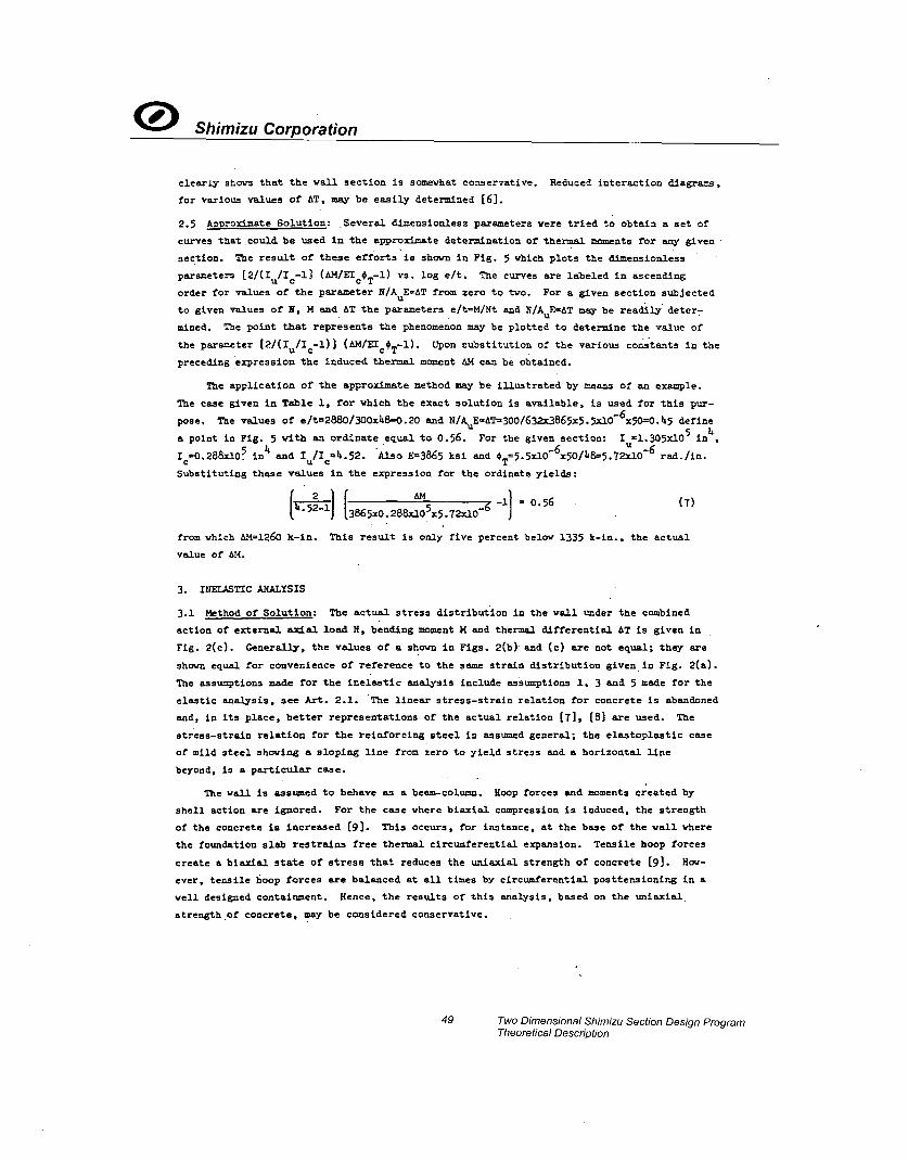
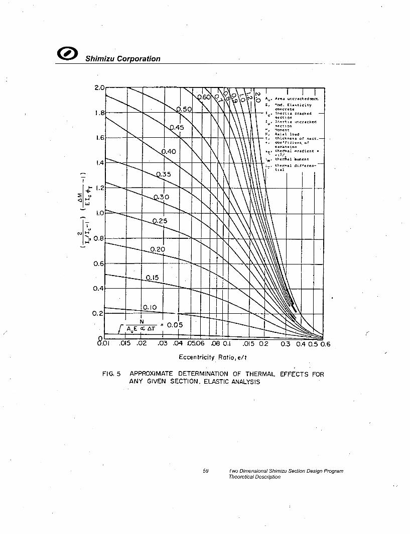
2.5 Ap2roximate Solution: Several dimensionless parameters were tried to obtain a set of
curves that could be used in the approximate determination of thermal moments for any given
section. The result of these efforts'is shown in Fig. 5 which plots the dimensionless
parameters [2/(I1/I-l] (&M/EIcOT-1) vs. log e/t. The curves are labeled in ascending
order for values of the parameter N/AuE=AT from zero to two. For a given section subjected
to given values of N, M and tAT the parameters e/t=M/Nt and N/AuE=AT may be readily deter-
mined. The point that represents the phenomenon may be plotted to determine the value of
the parameter (2/(Iu/Ic-l)] (AM/IIcOT-I). Upon tubstitution of the various constants in the
preceding expression the induced thermal moment AM can be obtained.
The application of the approximate method may be illustrated by means of an example.
The case given in Table 1, for which the exact solution is available, is used for this pur-
pose. The values of e/t=2880/300x48=0.20 and N/AuE dT=300/632x3865x5.5xl0-6 x50=0.45 define
5 i4a point in Fig. 5 with an ordinate equal to 0.56. For the given section: I =1.305xi0 in
Ic-0.288x.10 in4 and Iu/Ic4.52. Also E=3865 ksi and T,=5.5xlO-x 4O/48=5.72IO-6 rad.in.
Substituting these values in the expression for the ordinate yields:
[ .21J3865x0.268&105 -5-72.10-6
from which A1=1260 k-in. This result is only five percent below 1335 k-in., the actual
value of AM.
3. IUEIJASTIC ANALYSIS
3.1 Method of Solution: The actual stress distribution in the wall under the combined
action of external axial load N, bending moment M and thermal differential AT is given in
Fig. 2(c). Generally, the values of a shown in Figs. 2(b) and (c) are not equal; they are
shown equal for convenience of reference to the same strain distribution given in Fig. 2(a).
The assumptions made for the inelastic analysis include assumptions 1, 3 and 5 made for the
elastic analysis, see Art. 2.1. The linear stress-strain relation for concrete is abandoned
and, in its place, better representations of the actual relation [7], [8] are used. The
stress-strain relation for the reinforcing steel is assumed general; the elastoplastic case
of mild steel shoving a sloping line from zero to yield stress and a horizontal line
beyond, is a particular case.
The vail, is assumed to behave as a beam-column. Hoop forces and moments created by
shell action are ignored. For the case where biaxial compression is induced, the strength
of the concrete is increased [9]. This occurs, for instance, at the base of the wall where
the foundation slab restrains free thermal circumferential expansion. Tensile hoop forces
create a biaxial state of stress that reduces the uniaxial strength of concrete (9]. How-
ever, tensile hoop forces are balanced at all times by circumferential posttensioning in a
well designed containment. Hence, the results of this analysis, based on the uniaxial.
strength .of concrete, may be considered conservative.
49 Two Dimensional Shimizu Section Design ProgramTheoretical Description

0 Shimizu Corporation
The determination of the strain distribution and curvature of a reinforced concrete
section for given values of N and M has been solved [10] using Newton-Raphson's numerical
method. Thus, the initial strain distribution and curvature 0 shown in Fig. 2(a) is obtained.
The induced thermal moment AiM, due to the additional curvature *T imposed on the section,
is obtained using a variation of the method given in Ref. 10. It can be assumed that, for
a given section and material properties, N and M can be expressed as functions of 0 and c
as follows:
N =(8)
N MC4,c)
Let 00 and Eco be the initial values given in Fig. 2(a), corresponding to the external load
No and bending moment Mo. An expansion of Eq. 8 about No and M° using Taylor's theorem and
retaining only the linear terms yields:
N = No+ !N 6 + 3c 6cc (9)
M -M + 2m6 m 80 o 2EC 6 -Cc
where: 64 = increment of curvature necessary to produce N, M
6£ - increment of top strain necessary to produce N, Mc
3N/30 = rate of change of load with curvature
aN/ac€ = rate of change of load with top strain
ZM/30 = rate of change of moment with curvature
M/'Ec = rate of change of moment with top strain
For the unattached containment AN=O, i.e. N=No. Also 6
*=4
T and M-M0 =dM. Eq. 9 may be
transformed into.
c -31/3£ T (10)
&M = ; - 3M
where the four different rates of change can be determined numerically fron Eq. 8. Because
of the approximation involved in Eq. 9, it is likely that the solution obtained from Eq. 10
in the initial trial is only approximate and does not meet the desired accuracy. The neces-
sary check on the accuracy of the solution can be made using Eq. 8 with 4=f0+€T and
c=¢co +dc . If the resulting value of N is different from No, say N-N0 =RN•0, a better value
of £c may be obtained by adding to it dcc=AN/aN//cc as given by Eq. 9 for constant curvature.
Using the new value of cc and #o0+TV Eq. 8 is checked again. The process is repeated until
the desired accuracy is obtained.
A digital computer program based on the preceding method was used to analyze the
section of Table 1, for inelastic behavior. Hognestad's stress-strain diagram 17] was
adopted; the maximum stress of concrete being 0.85f; at a strain Cc=0.002, with a limiting
strain c u=0.003 and stress 0.72f;, at which crushing is assumed to take place. The stress-
strain diagram of the reinforcing steel was assumed elastoplastic.
50 Two Dimensional Shimizu Section Design ProgramTheoretical Description

0 Shimizu Corporation
3.2 Results of Analysis: The ultimate interaction diagram N vs. M ror the section is shown
in Fig. 6. The inside curves show the variation of the total moment M + AM; with N for
various values of the ratio e/t ranging from -0.5 to 1.0. Two sets of curves are shown; one
corresponding to positive, the other to negative values of e/t and AT. Both sets of curves
have co~on origins at N=O and terminate at their intersection with the interaction diagram.
The example given in Table 1 is solved in Fig. 6 for AT=100 0F. The result of the inelastic
aznalysis for AT=-50'F shows AM1367 k-in. vs. 1335 k-in. given by the elastic analysis, see
Table 1. The larger value given by the inelastic analysis may be attributed to the greater
slopes, i.e. tangent modulus, of the concrete stress-strain diagram at lower stresses as
compared to the secant modulus used in the elastic analysis. A comparison of results of
elastic vs. inelastic analysis when AT=-100 is given in Fig. 7 for three values of e/t. it
is easily seen that, for lower values of N, the inelastic analysis gives larger values of AM;
the reverse is true as the load N is increased. This is due to the softening of the section
as the steel reinforcing yields and the concrete stresses increase to a level where the
tangent modulus is small, or even negative as in the descending portion of the curve [7).
The inelastic analysis takes intoaccount these conditions; it is more realistic always,
but especially so for advanced loading.
The direct variation of the induced thermal moment AM with N, for various eccentricity
ratios ranging from -0.5 to 1.0, is shown in Fig. 8. It can be seen that for any value of
e/t there is a maximum AM created by a certain N beyond which, the induced thermal moment is
reduced rapidly as the value of N increases. For any given value of N, the maximum AM is
obtained with the smallest eccentricity ratio; a logical conclusion, considering the fact
that the extent of cracking and consequent loss of stiffness in the section due to thermal
effects are smaller as the eccentricity ratio decreases.
In view of the fact that thermal effects do not induce additional axial loads in wall
sections of unattached containments, a simple graphical solution of the problem can be
obtained with a set of K4-0 curves drawn for constant N. This is shown in Fig. 9(b) for
various values of the ratio N/Nu, where Nu is defined as the maximum load taken by the
section when €=0 and c,=,0.002, see Fig. 6. The induced thermal moment can be readily
obtained for any given value of M and N/Nu using Fig. 9(b). Upon location of the point with
the given M on the corresponding N/Nu curve, one need only add graphically to its abscissae
the value *T.=oaT, after which proceeding vertically to intersect the curve yields AM.
Obviously, the effect of negative *T may be obtained similarly by subtracting from the given
abscissae. Since the slope of the various curves is different, it is easy to see from Fig.
9(b) that for any given M, the induced moment AM depends on the value of N/N . As the slope
diminishes for the higher values of M, thermal curvatures induce smaller moments. Signifi-
cantly, for N/Nu=O, any thermal effect in the flat portion of the curve results in a very
small AM.
The variation of AM with M for various values of N/INu is given in Fig. 9(a). The
largest effects occur when N/Nu is close to 0.4. This value correspondp closely to that of
N., the load at the balanced point, see Fig. 6; a condition that exists in a section when,
at failure, the tension steel is at initial yielding. It is likely that for any given
section maximum thermal effects occur when subjected to axial loads close to the balanced
load.
51 Two Dimensional Shimizu Section Design ProgramTheoretical Description

OShimizu Corporation
4. CONCLUSIONS
As a result of the preceding work, the following conclusions are drawn:
1. For a given section, the moment induced by a given thermal differential depends on the
external axial load and bending moment to which the sedtion is subjected.
2. Upper and lower limits exist for elastically determined thermal moments in any section
under a given thermal differential. The upper limit is given by the product of the
modulus of elasticity of concrete, the thermal curvature and the moment of inertia of
the uncracked section. The lover limit is given by a similar product, except that the
moment of inertia of the cracked section is used.
3. At service load conditions, elastic analysis renders thermal effects that are smaller
than those obtained using inelastic analysis. The reverse is true for higher levels of
loading.
4. Inelastic analysis should be used to determine thermal effects in walls of containment
structures. Ultimate conditions, and hence, safety of design, can only be determined
using inelastic analysis.
5. ACMIOWLEDGM-OTS
This investigation was proposed and sponsored by Sargent & Lundy Engineers of Chicago,
Illinois and the Civil Engineering Department of the University of Illinois at Urbana. The
elastic analysis was carried out by the writer during the summer of 1970 for Sargent & Lundby's
Analytical & Computer Division. The inelastic analysis was accomplished at the University of
Illinois during the fall semester of this academic year. The author is grateful to M. Zar,
S. L. Chu, A. Walser and J. Kontoudakis, of Sargent & Lundy, and R. Wetzel of the University
of Illinois, for assistance rendered during the investigation.
4
0
1~
52 Two Dimensional Shimizu Section Design ProgramTheoretical Description
0Shimizu Corporation
RE CES
[l] ACI Standard 318-63, "Building Code Requirements for Reinforced Concrete," AmericanConcrete Institute, P. 0. Box 4754 Redford Station, Detroit, Mich. 482l9.
[2] ACI Special Publication No. 3, "Reinforced Concrete Design Handbook - Working StressDesign," 3rd Edition.
[3] ACI Special Publication No. 7, "Ultimate Strength Design of-Reinforced ConcreteColumns."
[4] KRACHATURIAN, N., GURFINKEL, G., "Prestressed Concrete," Chapter 3i, McGraw-Hill BookCompany, N. Y., 1969.
[5] TAN, C. P., -"Concrete Containment for Reactors State of Art," Journal of theStructural Division, ASCE, Vol. 96, No. ST7, Proc. Paper 7424, July 1970,pp. 1543-1566.
[6] GURFINKEL, G., "Thermal Effects in Walls of Nuclear Containments," Internal ReportNo. 42 of the Analytical and Computer Division of Sargent & Lundy Engineers, Chicago,Illinois, August 1970.
[7] HOGNESTAD, E., "A Study of Combined Bending and Axial Load in Reinforced ConcreteMembers," Bulletin No. 399, University of Illinois Engineering Experiment Station,Urbana, 1951.
_[8] TODESCHIBI, C. E., BIANCHINI, A. C., and KESLER, C. E., "Behavior of Concrete ColumnsReinforced vith High-Strength Steels," Journal of the American Concrete Institute,Vol. 61, No. 6, June 1964, pp. 701-716.
[9] KUPFER, H., HILSDORF, H. K., and RUSCH, H., "Behavior of Concrete Under BiaxialStresses," Journal of the American Concrete Institute, Vol. 66, No. 8, August 1969,pp. 656-666.
110] GURFIN1E, G., and ROBINSON, A. R., "Determination of Strain Distribution and
Curvature in a Reinforced Concrete Section Subjected to Bending Moment and Longitudinal
Load," Journal of the American Concrete Institute, Vol. 64, No. 7, July 1967,pp. 398-403.
53 Two Dimensional Shimizu' Section Design ProgramTheoretical Description

0 Shimizu Corporation
Table 1. Illustration of Iteration Method*
CYCLE a N(e'+a) l@t
(in) Kip-in Kip-in
-NiIsKip-in
R
Kip-in
1
2
3
4
5
6
7
24.oo
11.82
24.77
25.51
33.06
35.09
35.38
2612.41
-1039.75
2843.82
3066.25
5333.12
5940.51
6025.58
776.91
646.33
798.53
821.21
1176.19
1314.42
1335.39
- 6226.78
-47225.92
- 6221.82
- 6236.44
- 7005.70
- 7315.91
- 7361.3o
- 2837.46
-47619.34
- 2579.47
- 2348.98
- 496.39
- 60.98
0.33
For the given case: b=12 in, t=48 in, A,=2.75 in2
, d=45 in,
A =1.25 in2, d'=10 in, f'=c .5 ksi, E3865 ksi, f =60 ksi,8 C "y
Es-29,000 ksi, n=T.5, T1 =1100F, T2 =60
0F, AT=-50F, ==5.5x10-/OF,
T=5.72xlO-6 in-1 , N=300 kips, M=2880k-in, e=9.6
in, e'=-15.29 in;
1, i, S and R depend on the value of a. The thermal moment
&M=-1335 k-in.
54, Two Dimensional Shimizu Section Design ProgramTheoretical Description

0 Shimizu Corporation
Centroidal Axis Uncracked
N
To
(a)Vertical Section of Wall
SteelLiner
(b) Horizontal Section of Wall
(c) Temperature Strains
FIG. I CONTAINMENT WALL UNDER ECCENTRICLOADING AND THERMAL DIFFERENTIAL
55 Two Dimensional Shimizu Section Design ProgramTheoretical Description

0 Shimizu Corporation
(C(a) Strain Distribution
e e'
ff
Ts =es Es AsI
Cc 1/2 fc ab
(b) Stress Distribution, Elastic
, ,Cs ICcfbdx0
(c) Stress Distribution, Inelastic
FIG. 2 STRAIN AND STRESS DISTRIBUTIONS IN CONTAINMENT WALL
56 Two Dimensional Shimizu Section Design ProgramTheoretical Description

® Shimizu Corporation
0.
z0
.J
0•
Restraining Temperature Moment, AM , 1000 k-in
FIG. 3 THERMAL MOMENTS IN A GIVEN SECTION UNDER 1000 FTEMPERATURE DIFFERENTIAL. ELASTIC ANALYSIS
57 Two Dimensional Shimizu Section Design ProgramTheoretical Description

5c cI I , I ILoad Combination Table
Working Stress Yield Strength400 K Permanent Loads (PL) P=I.OPL+I.5P N
L PL 4 Pressure (P) Q= L.OPL+ E oM:PL+ Earthquake (E) R =I.0OPLP+E P + E 0
300 N=PL+P+E S = I.OPL+125P+1.25E , 0O=Pre ssure Test
05Z)
2 0 0 o _,_ ,L_ _
o sOO -SArj0
< Section of Wo'll000
-,°° -OO 21_N .
•_•+-200 - T 4,6" T,DAT '.TI--To
-6000 -4000 -2000 0 2000 4000 6000
Bending Moment, kip-in.
(FIG. 4 THERMAL EFFECTS IN WALL OF ACTUAL CONTAINMENT-,o
t
02Shimizu Corporation
2.0
I1.8
1.6
N N' ' I I I. _
V.6o bC
~k 45I
Au, Artj uncrcked.se
E, .od. Elasticityconcrete
1., 1nertia cracked -
sectionblx51men t
N, Axial loadt, thickness of lect.-
Co~e'f~cient of
ex~nnsion,,, t "ermal nradient -
ther~aI *ccent
theral di~ecet,-
N
A
0.40 Ni\\\I.
1
0.
0.
0.
.2
.0
,8
.6
.-- 35 K \N
I-.~--- I - N -t ~1 -~ + - -4-4 ~.
.30
| i
N
f ~ - - -~ N~ - ~d -%--4---- -4i4-44---+----- 4-4-.2 ],,,
N',
Sf i
020 N
.
NN
T•L
2NA E ••T ! 0
o-(0.01 .015 .02 .03 .04 05.06 .08 0.1 .015 0.2
Eccentricity Ratio, e/t
0.3 0.4 0.5 0.6
EFFECTS FORFIG. 5 APPROXIMATE DETERMINATION OF THERMALANY GIVEN SECTION. ELASTIC ANALYSIS
59 Two Dimensional Shimizu Section Design ProgramTheoretical Description

3•,5 1 -r ý 811.4,..•
Example GivenN=300k, M=2880 k-in. IOO0F "3.0 ATOO0= F, as0.55 xlOj Determine - 1 -1.?e=9.6 in.,e/t:O.2.Graph yields M-tAM= •'M+
2.5 5100 k-in -Hence ,AM=2220k-in. Ultimate Interaction 02.5 - • ~ ~~D iag r am TO 1:,.• . -;:\; Tj
"20 -00 e/t =oo 7 0_ e/t=N• o8
-- 1.5- 0.05 AT T,-T0 06
- .
*1 0.0.5o
C 16 -14 -12 -)0 -8 -6 -4 -2 0 2 4 6 8 10 12 14 16
Total Moment M + AM, 1O00k-in.
z FIG. 6 THERMAL EFFECTS IN A GIVEN SECTION FOR VARIOUS ECCENTRICITY RATIOS. INELASTICP ANALYSISco

0 Shimizu Corporation
°.
0-J
0
100 150 200 250 300 350 400 450Restraining Temperature Moment, AM, ki,-ft
FIG. 7 COMPARISON OF ELASTIC VS. INELASTIC THERMAL EFFECTS
61 Two Dimensional Shimizu Section Design ProgramTheoretical Description

-6 -4 -2 0 2 4 63W
AT -I00 F AT I00 F N
2.5- /t,-Q02 -2.5 0
/t =0
2 -2.0
z"
°1.5- -1.5.20.
1.0
C- -0.020(1.0
0.55
CDCInduced Thermal Moment AM, 1000 k-in.
0FIG. 8 THERMAL EFFECTS IN A GIVEN SECTION UNDER 10001F TEMPERATURE.Z" DIFFERENTIAL. INELASTIC ANALYSIS

N
0
0
0
i,
0
0.5
bJ
w
0)C.,
(b0CD
(no
CD "J5 4 3 2 I 0 0.4 0.8 1.2 1.6 20 2.4 2.1(a)lnduced Thermal Moment AM,IOOOk-in. (b)Curvature 0 x I04 in."
FIG. 9 THERMAL EFFECTS AND MOMENT-CURVATURE RELATIONS IN A GIVEN SECTION FORVARIOUS AXIAL-LOAD RATIOS

0Shimizu Corporation
DISCUSSION
Q iR. S. BEKOWICH, U. S. A.
1. Does the method discussed apply to the analysis of the containment around a large openingsuch as an equipment notch ?
2. Does the method take into consideration the various materials present such as concretereinforcing steel, liner, and prestressing. Also does it consider the effect of concrete crack-ing ?
A J. M. DOYLE, U. S. A., p. p. G. GURFINKEL, U. S. A.
1. The methods presented in the paper were applied only to areas of the containment locatedaway from any openings or penetrations. That is, in a section with no discontinuities ingeometry.
2. The analysis included the effects of reinforcing steel and cracking of the concrete. It didnot include the effect of the liner.
64 Two Dimensional Shimizu Section Design ProgramTheoretical Description

ENCLOSURE 4
MFN 06-191, SUPPLEMENT 6
AFFIDAVIT

GE Hitachi Nuclear Energy
AFFIDAVIT
I, David H. Hinds, state as follows:
(1) I am the Manager, New Units Engineering, GE Hitachi Nuclear Energy ("GEH")and have been delegated the function of reviewing the information described inparagraph (2) which is sought to be withheld, and have been authorized to apply forits withholding.
(2) The information sought to be withheld is contained in Enclosure 2 of GEH letterMFN 06-191, Supplement 6, James C. Kinsey to U.S. Nuclear RegulatoryCommission, Response to Portion of NRC Request for Additional Information LetterNo. 38 Related to ESB WR Design Certification Application - Structural Analysis -RAI Numbers 3.8-25 S04, 3.8-41 S04 and 3.8-91 S04 (GEH ProprietaryInformation), dated December 7, 2007. The proprietary information in Enclosure 2,Two Dimensional Shimizu Section Design Program SSDP-2D TheoreticalDescription, is identified by a dark red font with dotted underline inside doublesquare brackets. Figures and large equation objects are identified with doublesquare brackets before and after the object. In each case, the superscript notation 131
refers to Paragraph (3) of this affidavit, which provides the basis for the proprietarydetermination.
(3) In making this application for withholding of proprietary information of which it isthe owner, GEH relies upon the exemption from disclosure set forth in the Freedomof Information Act ("FOIA"), 5 USC Sec. 552(b)(4), and the Trade Secrets Act, 18USC Sec. 1905, and NRC regulations 10 CFR 9.17(a)(4), and 2.390(a)(4) for "tradesecrets" (Exemption 4). The material for which exemption from disclosure is heresought also qualify under the narrower definition of "trade secret", within themeanings assigned to those terms for purposes of FOIA Exemption 4 in,respectively, Critical Mass Energy Project v. Nuclear Regulatory Commission,975F2d871 (DC Cir. 1992), and Public Citizen Health Research Group v. FDA,704F2d1280 (DC Cir. 1983).
(4) Some examples of categories of information, which fit into the definition ofproprietary information, are:
a. Information that discloses a process, method, or apparatus; includingsupporting data and analyses, where prevention of its use by GEH'scompetitors without license from GEH constitutes a competitive economicadvantage over other companies;
b. Information which, if used by a competitor, would reduce his expenditure ofresources or improve his competitive position in the design, manufacture,shipment, installation, assurance of quality, or licensing of a similar product;
Af- MFN 06-191, Supp. 6 Page I of 3

c. Information, which reveals aspects of past, present, or future GEH customer-funded development, plans and programs, resulting in potential products toGEH;
d. Information, which discloses patentable subject matter for which it may bedesirable to obtain patent protection.
The information sought to be withheld is considered to be proprietary for the reasonsset forth in paragraphs (4)a., and (4)b, above.
(5) To address 10 CFR 2.390 (b) (4), the information sought to be withheld is beingsubmitted to NRC in confidence. The information is of a sort customarily held inconfidence by GEH, and is in fact so held. The information sought to be withheldhas, to the best of my knowledge and belief, consistently been held in confidence byGEH, no public disclosure has been made, and it is not available in public sources.All disclosures to third parties including any required transmittals to NRC, havebeen made, or must be made, pursuant to regulatory provisions or proprietaryagreements, which provide for maintenance of the information in confidence. Itsinitial designation as proprietary information, and the subsequent steps taken toprevent its unauthorized disclosure, are as set forth in paragraphs (6) and (7)following.
(6) Initial approval of proprietary treatment of a document is made by the manager ofthe originating component, the person most likely to be acquainted with the valueand sensitivity of the information in relation to industry knowledge. Access to suchdocuments within GEH is limited on a "need to know" basis.
(7) The procedure for approval of external release of such a document typically requiresreview by the staff manager, project manager, principal scientist or other equivalentauthority, by the manager of the cognizant marketing function (or his delegate), andby .the Legal Operation, for technical content, competitive effect, and determinationof the accuracy of the proprietary designation. Disclosures outside GEH are limitedto regulatory bodies, customers, and potential customers, and their agents, suppliers,and licensees, and others with a legitimate need for the information, and then only inaccordance with appropriate regulatory provisions or proprietary agreements.
(8) The information identified in paragraph (2), above, is classified as proprietarybecause it contains details of GEH's design and evaluation methodology developedby GEH over a period of several years at a substantial cost.
The development of these processes along with the interpretation and application ofthe analytical results is derived from the extensive experience database thatconstitutes a major GEH asset.
Af- MFN 06-191, Supp. 6 Page 2 of 3

(9) Public disclosure of the information sought to be withheld is likely to causesubstantial harm to GEH's competitive position and foreclose or reduce theavailability of profit-making opportunities. The information is part of GEH'scomprehensive BWR safety and technology base, and its commercial value extendsbeyond the original development cost. The value of the technology base goesbeyond the extensive physical database and analytical methodology and includesdevelopment of the expertise to determine and apply the appropriate evaluationprocess. In addition, the technology base includes the value derived from providinganalyses done with NRC-approved methods.
The research, development, engineering, analytical and NRC review costs comprisea substantial investment of time and money by GEH.
The precise value of the expertise to devise an evaluation process and apply thecorrect analytical methodology is difficult to quantify, but it clearly is substantial.
GEH's competitive advantage will be lost if its competitors are able to use the resultsof the GEH experience to normalize or verify their own process or if they are able toclaim an equivalent understanding by demonstrating that they can arrive at the sameor similar conclusions.
The value of this information to GEH would be lost if the information weredisclosed to the public. Making such information available to competitors withouttheir having been required to undertake a similar expenditure of resources wouldunfairly provide competitors with a windfall, and deprive GEH of the opportunity toexercise its competitive advantage to seek an adequate return on its large investmentin developing these very valuable analytical tools.
I declare under penalty of perjury that the foregoing affidavit and the matters statedtherein are true and correct to the best of my knowledge, information, and belief.
Executed on this 12th day of December 2007.
David H. HindsGE Hitachi Nuclear Energy
Af- MFN 06-191, Supp. 6 Page 3 of 3