mfab3000 mfab3010 mfab3000l mfab3000/110 mfab3024 ... · pdf filenice swing gate opener...
TRANSCRIPT

Nice
Swing gate opener
MFAB3000MFAB3010MFAB3000LMFAB3000/110MFAB3024MFAB3024HS
EN - Instructions and warnings for installation and use
IT - Istruzioni ed avvertenze per l’installazione e l’uso
FR - Instructions et avertissements pour l’installation et l’utilisation
ES - Instrucciones y advertencias para la instalación y el uso
DE - Installierungs-und Gebrauchsanleitungen und Hinweise
PL -Instrukcjeiostrzeżeniadoinstalacjiiużytkowania
NL - Aanwijzingen en aanbevelingen voor installatie en gebruik

EN
1 – English
GENERAL SAFETY WARNINGSAND PRECAUTIONS1
GENERAL WARNINGS
• ATTENTION! - Important safety instructions. Follow all instruc-tions as improper installation may cause serious damage.
• ATTENTION! - Important safety instructions. It is important for you to comply with these instructions for your own and other people’s safety. Keep these instructions.
• Before commencing the installation, check the “Technical character-istics” (in this manual), in particular whether this product is suitable for automating your guided part. If it is not suitable, DO NOT contin-ue with the installation.
• The product cannot be used before it has been commissioned as specified in the chapter on “Testing and commissioning”.
• ATTENTION! - According to the most recent European legisla-tion, the implementation of an automation system must com-ply with the harmonised standards provided by the Machinery Directive in force, which enables declaration of the presumed conformity of the automation. Taking this into account, all op-erations regarding connection to the electricity grid, as well as product testing, commissioning and maintenance, must be performed exclusively by a qualified and skilled technician!
• Before proceeding with the installation of the product, check that all the materials are in good working order and suited to the intended applications.
• ATTENTION! - In order to avoid any danger from inadvertent resetting of the thermal cut-off device, this appliance must not be powered through an external switching device, such as a timer, or connected to a supply that is regularly powered or switched off by the circuit.
• Provide a disconnection device (not supplied) in the plant’s power supply grid, with a contact opening distance permitting complete dis-connection under the conditions dictated by overvoltage category III.
• Handle the product with care during installation, taking care to avoid crushing, denting or dropping it, or allowing contact with liquids of any kind. Keep the product away from sources of heat and naked flames. Failure to observe the above can damage the product, and increase the risk of danger or malfunction. Should this happen, stop installation immediately and contact Customer Service.
• The manufacturer assumes no liability for damage to property, items or persons resulting from non-compliance with the assembly instruc-tions. In such cases the warranty for material defects is excluded.
• The weighted sound pressure level of the emission A is lower than 70 dB(A).
• Before working on the system (maintenance, cleaning), always dis-connect the product from the mains power supply.
• Check the system periodically, in particular all cables, springs and supports to detect possible imbalances, signs of wear or damage. Do not use, if repairs or adjustments are necessary, since installation failure or an incorrectly balanced automation may cause injury.
• The packing materials of the product must be disposed of in compli-ance with local regulations.
• When operating a biased-off switch, make sure that other persons are kept away.
• When operating the gate, keep an eye on the automated mecha-nism and keep all bystanders at a safe distance until the movement has been completed.
• Do not operate the product if anyone is working nearby; disconnect its power supply before permitting such work to be done.
• If the power cable is damaged, it must be replaced by the manufac-turer or by an appointed servicing company or similarly qualified per-son in order to prevent any form of risk.
INSTALLATION WARNINGS
• Prior to installing the drive motor, check that all mechanical compo-nents are in good working order and properly balanced, and that the automation moves correctly.
• If the gate or door being automated has a pedestrian gate, then the system must include a control device that will inhibit the operation of the motor when the pedestrian gate is open.
• Make sure that the control devices are kept far from moving parts but nonetheless in a visible position. Unless a selector is used, the control devices must be installed at a height of at least 1.5 m and must not be accessible.
• Ensure that entrapment between the driven part and the surround-ing fixed parts due to the opening movement of the driven part is avoided.
• Permanently fix the label concerning the manual release adjacent to its actuating member.
• After installing the drive motor, make sure that the mechanism, pro-tective system and all manual manoeuvres operate properly.
DESCRIPTION OF THE PRODUCTAND DESTINATION OF USE2
MFAB(...) is a gearmotor designed for the automation of single-leaf or double-leaf gates. WARNING! – Any applications other than those described above or under different conditions from those specified in this manual are forbidden.
MFAB(...) operates with electric power. In the event of a power failure, the gearmotor can be released using suitable keys in order to move the leaves manually.
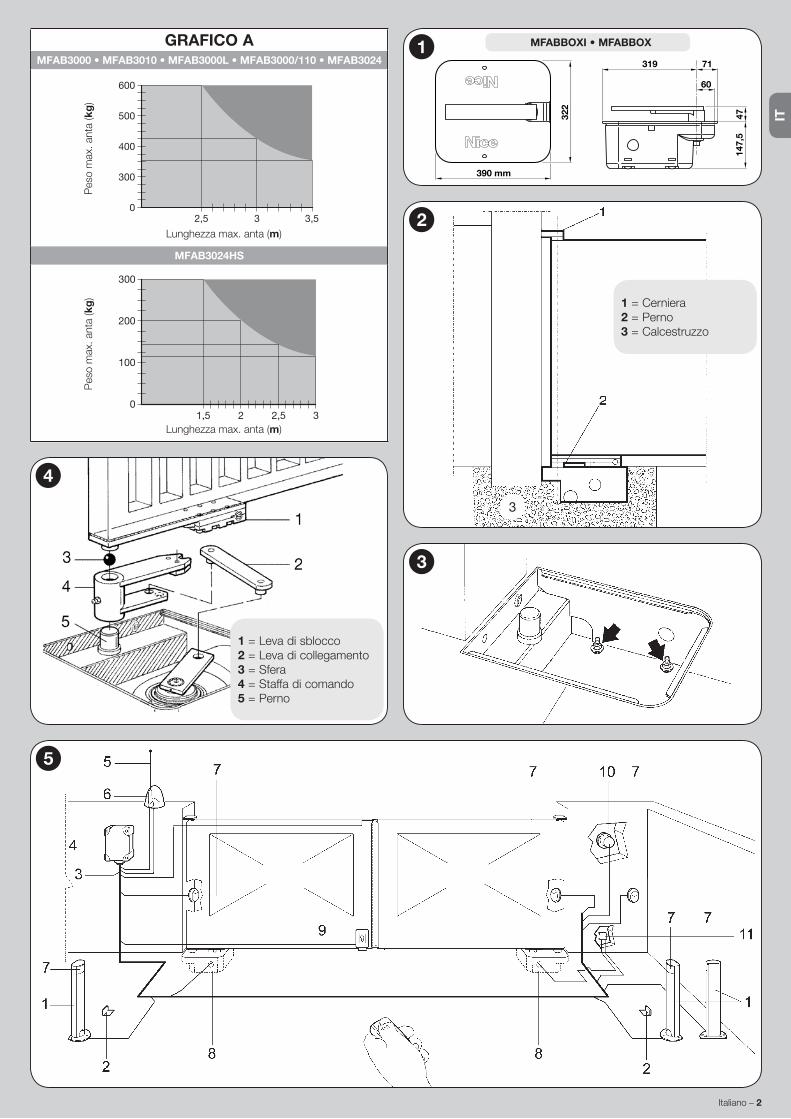
INSTALLATION33.1 - Preliminary ChecksBefore proceeding with the installation, make sure that the structure is suitable and that it complies with the regulations in force. In particular, you need to make sure that: • there are no points of friction in the opening and closing travel of the gate; • the gate is well balanced, i.e., once it is stopped in any position it should not show a tendency to start moving again; • the gate opens and closes smoothly and noiselessly; • the area selected for gearmotor installation enables easy and safe manual manoeuvring; • check the integrity of the package; • make sure that the mounting area is compatible with the dimensions of the box (fig.1); • provide a closing strike and, if possible, also an opening strike.
WARNING! – Please keep in mind that MFAB(...) is designed to drive an efficient, safe gate (with one or two leaves), and is not intended to make up for defects resulting from improper installation or poor maintenance.
3.2 - Operating LimitsThe shape and height of the gate (e.g. blind) and the weather conditions (e.g. strong winds) may significantly reduce the values shown in the Graph A.Note – If any of the gate leaves is wider than 2.5 metres, we recommend the installation of an electric lock (PLA10 or PLA11).
3.3 - Mounting
3.3.1 - Overall Dimensions and Positioning of Foundation Box1. Excavate the foundation hole based on the overall dimensions; provide
good drainage in order to prevent water stagnation.2. Fasten the accessory for the opening limit switch to the box, carefully ob-
serving the directions and measurements shown in the fig. 6 to avoid incor-rect installation.
3. Place the box inside the foundation hole; the stud must be aligned with the axis of the hinge (fig. 2).
4. Provide a duct for the electrical cables and a drainage pipe.5. Bury the foundation box in concrete, making sure it is set level. 6. Mount the control bracket on the box’s stud along with the ball.7. Set the gate leaf on the release lever and weld them securely.8. Grease using a suitable grease nozzle.
3.3.2 - Installation of MFAB(...) Gearmotor1. Remove the nuts and washers shown in the fig. 3.2. Place the gearmotor inside the foundation box making sure it faces the cor-
rect direction.
ENGLISHInstructions translated from Italian

EN
English – 2
1 = Release lever2 = Connecting lever3 = Ball4 = Control bracket5 = Pin
4
3
GRAPH AMFAB3000 • MFAB3010 • MFAB3000L • MFAB3000/110 • MFAB3024
2,5 3 3,50
300
400
500
600
Max. length of leaf (m)
Max
. wei
ght o
f lea
f (kg
)
MFAB3024HS
1,5 2,52 30
100
200
300
Max. length of leaf (m)
Max
. wei
ght o
f lea
f (kg
)
5
1 = Hinge2 = Pin3 = Concrete
2
3
147,
547
71319
60
322
390 mm
1 MFABBOXI • MFABBOX
3 – English
EN
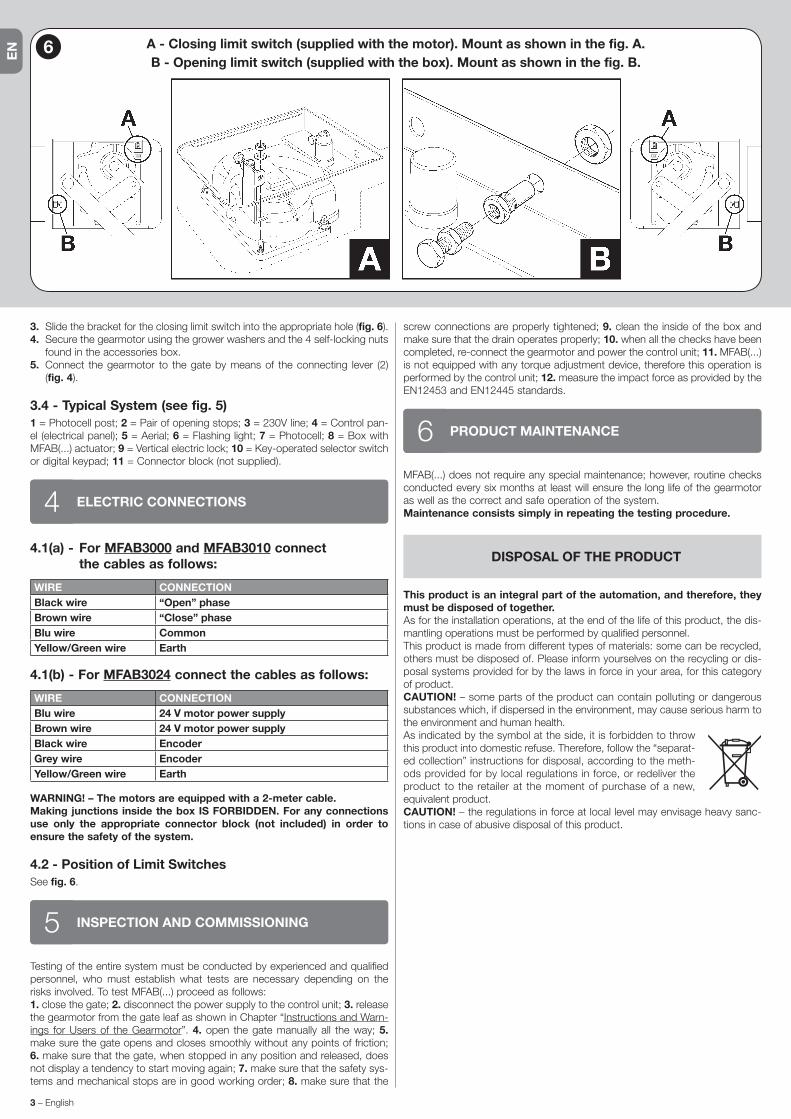
3. Slide the bracket for the closing limit switch into the appropriate hole (fig. 6).4. Secure the gearmotor using the grower washers and the 4 self-locking nuts
found in the accessories box.5. Connect the gearmotor to the gate by means of the connecting lever (2)
(fig. 4).
3.4 - Typical System (see fig. 5)1 = Photocell post; 2 = Pair of opening stops; 3 = 230V line; 4 = Control pan-el (electrical panel); 5 = Aerial; 6 = Flashing light; 7 = Photocell; 8 = Box with MFAB(...) actuator; 9 = Vertical electric lock; 10 = Key-operated selector switch or digital keypad; 11 = Connector block (not supplied).
ELECTRIC CONNECTIONS44.1(a) - For MFAB3000 and MFAB3010 connect
the cables as follows:
WIRE CONNECTIONBlack wire “Open” phaseBrown wire “Close” phaseBlu wire CommonYellow/Green wire Earth
4.1(b) - For MFAB3024 connect the cables as follows:
WIRE CONNECTIONBlu wire 24 V motor power supplyBrown wire 24 V motor power supplyBlack wire EncoderGrey wire EncoderYellow/Green wire Earth
WARNING! – The motors are equipped with a 2-meter cable. Making junctions inside the box IS FORBIDDEN. For any connections use only the appropriate connector block (not included) in order to ensure the safety of the system.
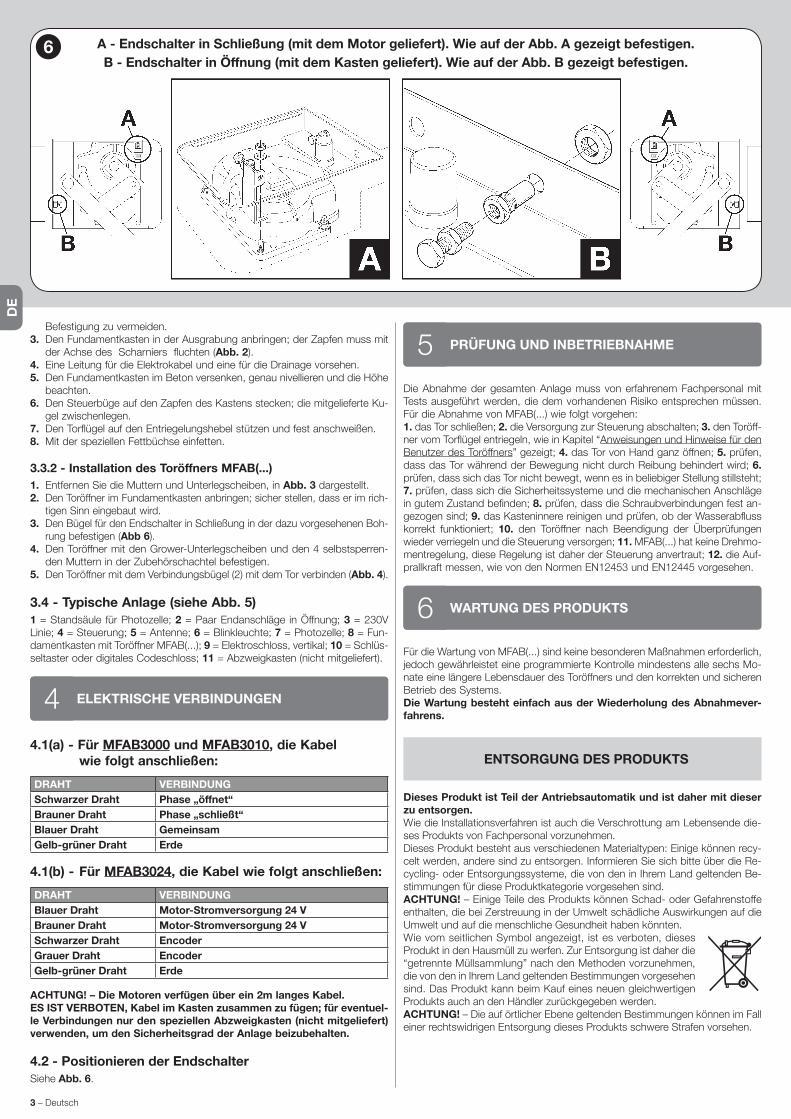
4.2 - Position of Limit SwitchesSee fig. 6.
INSPECTION AND COMMISSIONING5Testing of the entire system must be conducted by experienced and qualified personnel, who must establish what tests are necessary depending on the risks involved. To test MFAB(...) proceed as follows:1. close the gate; 2. disconnect the power supply to the control unit; 3. release the gearmotor from the gate leaf as shown in Chapter “Instructions and Warn-ings for Users of the Gearmotor”. 4. open the gate manually all the way; 5. make sure the gate opens and closes smoothly without any points of friction; 6. make sure that the gate, when stopped in any position and released, does not display a tendency to start moving again; 7. make sure that the safety sys-tems and mechanical stops are in good working order; 8. make sure that the
screw connections are properly tightened; 9. clean the inside of the box and make sure that the drain operates properly; 10. when all the checks have been completed, re-connect the gearmotor and power the control unit; 11. MFAB(...) is not equipped with any torque adjustment device, therefore this operation is performed by the control unit; 12. measure the impact force as provided by the EN12453 and EN12445 standards.
PRODUCT MAINTENANCE6MFAB(...) does not require any special maintenance; however, routine checks conducted every six months at least will ensure the long life of the gearmotor as well as the correct and safe operation of the system.Maintenance consists simply in repeating the testing procedure.
DISPOSAL OF THE PRODUCT
This product is an integral part of the automation, and therefore, they must be disposed of together.As for the installation operations, at the end of the life of this product, the dis-mantling operations must be performed by qualified personnel.This product is made from different types of materials: some can be recycled, others must be disposed of. Please inform yourselves on the recycling or dis-posal systems provided for by the laws in force in your area, for this category of product.CAUTION! – some parts of the product can contain polluting or dangerous substances which, if dispersed in the environment, may cause serious harm to the environment and human health.As indicated by the symbol at the side, it is forbidden to throw this product into domestic refuse. Therefore, follow the “separat-ed collection” instructions for disposal, according to the meth-ods provided for by local regulations in force, or redeliver the product to the retailer at the moment of purchase of a new, equivalent product.CAUTION! – the regulations in force at local level may envisage heavy sanc-tions in case of abusive disposal of this product.
6 A - Closing limit switch (supplied with the motor). Mount as shown in the fig. A.B - Opening limit switch (supplied with the box). Mount as shown in the fig. B.

EN
English – 4
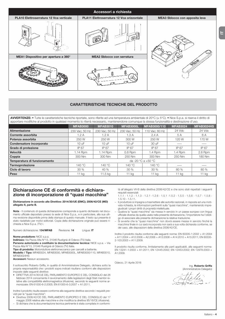
CAUTIONS: • The technical features set out refer to an ambient temperature of 20°C (± 5°C). • Nice S.p.a. reserves the right to make alterations to the product any time it deems it necessary, keeping the same functionality and destination of use.
MFAB3000 MFAB3010 MFAB3000L MFAB3000/110 MFAB3024 MFAB3024HSPower supply 230 Vac; 50 Hz 230 Vac; 50 Hz 230 Vac; 50 Hz 110 Vac; 60 Hz 24 Vdc 24 VdcAbsorbed current 1.2 A 1.2 A 1.3 A 2.4 A 5 A 6 AAbsorbed power 250 W 250 W 300 W 250 W 120 W 170 WIncorporated capacitor 10 uF 10 uF 10 uF 30 uF ––– –––Protection class IP 67 IP 67 IP 67 IP 67 IP 67 IP 67Speed 1.14 Rpm 1.14 Rpm 0.8 Rpm 1.4 Rpm 1.4 Rpm 2.6 RpmTorque 300 Nm 300 Nm 250 Nm 300 Nm 250 Nm 180 NmOperating temperature -20 °C to +50 °CThermal protection 140 °C 140 °C 140 °C 140 °C ––– –––Work cycle 30 % 40 % 30 % 30 % 80 % 80 %Weight 11 kg 11.5 kg 11 kg 11 kg 11 kg 11 kg
TECHNICAL FEATURES OF THE PRODUCT
Accessories On Request
PLA10 Vertical electric lock 12 Vac PLA11 Horizontal electric lock 12 Vac MEA3 Lever-operated release mechanism
MEA1 360° opening device MEA2 Key-operated release mechanism
CE declaration of conformity and declaration of incorporation for a “quasi-machine”Declaration in accordance with Directives: 2014/30/UE (EMC); 2006/42/EC (MD) annex II, part B.
Note - The content of this declaration corresponds to the declaration made in the of-ficial document filed in the offices of Nice S.p.a., and particularly the latest version thereof available prior to the printing of this manual. The text contained here has been adapted to meet editorial requirements. A copy of the original declaration may be re-quested from Nice S.p.a. (TV) I.
Declaration number: 134/MFAB Revision: 14 Language: EN
Name of manufacturer: NICE S.p.A.Address: Via Pezza Alta N°13, 31046 Rustignè di Oderzo (TV) Italy.Person authorized to provide technical documentation: NICE S.p.A. – Via Pezza Alta N°13, 31046 Rustignè di Oderzo (TV) Italy.Product type: Electric gearmotor for swing gates.Model / Type : MFAB3024, MFAB3000, MFAB3000L, MFAB3000/110, MFAB3010, MFAB3024HSAccessories: No accessory.
The undersigned Roberto Griffa, as Chief Executive Officer, hereby declares under his own responsibility that the products identified above comply with the provisions of the following directives:• DIRECTIVE 2014/30/UE OF THE EUROPEAN PARLIAMENT AND COUNCIL of
February 26 2014 concerning alignment of Member States’ legislation regarding electromagnetic compatibility (consolidated text), according to the following harmo-nized standards: EN 61000-6-2:2005; EN 61000-6-3:2007 + A1:2011.
The product also complies with the following directive in accordance with the require-ments for “quasi-machines”:• Directive 2006/42/EC OF THE EUROPEAN PARLIAMENT AND COUNCIL of May
17 2006 regarding machines and amending directive 95/16/EC (consolidated text).– I declare that the pertinent technical documentation has been prepared in accord-
ance with Annex VII B to Directive 2006/42/EC and that the following essential re-quirements have been met:
1.1.1 - 1.1.2 - 1.1.3 - 1.2.1 -1.2.6 - 1.5.1 -1.5.2 - 1.5.5 - 1.5.6 - 1.5.7 - 1.5.8 - 1.5.10 - 1.5.11.
– The manufacturer agrees to send the national authorities pertinent information on the “quasi-machine” in response to a motivated request without affecting its intel-lectual property rights.
– If the “quasi-machine” is operated in a European country with an official language other than the language used in this declaration, the importer must associate a translation with this declaration.
– The “quasi-machine” must not be operated until the final machine in which it is to be incorporated is declared to conform to the provisions of Directive 2006/42/EC, if applicable to it.
The product also complies with the following standards: EN 60335-1:2002 + A1:2004 + A11:2004 + A12:2006 + A2:2006 + A13:2008 + A14:2010 + A15:2011; EN 60335-2-103:2003 + A11:2009.
The parts of the product which are subject to the following standards comply with them: EN 13241-1:2003 + A1:2011; EN 12445:2002; EN 12453:2002; EN 12978:2003 + A1:2009.
Oderzo, April 21 2016Eng. Roberto Griffa
(Chief Executive Officer)

IT
1 – Italiano
AVVERTENZE E PRECAUZIONI GE NERALIPER LA SICUREZZA1
AVVERTENZE GENERALI
• ATTENZIONE! - Istruzioni importanti per la sicurezza. Seguire tutte le istruzioni poiché l’installazione non corretta può cau-sare gravi danni.
• ATTENZIONE! - Istruzioni importanti per la sicurezza. Per la sicurezza delle persone è importante seguire queste istruzio-ni. Conservare queste istruzioni.
• Prima di iniziare l’installazione verificare le “Caratteristiche tecniche del prodotto”, in particolare se il presente prodotto è adatto ad auto-matizzare la vostra parte guidata. Se non è adatto, NON procedere all’installazione.
• Il prodotto non può essere utilizzato prima di aver effettuato la messa in servizio come specificato nel capitolo “Collaudo e messa in servizio”.
• ATTENZIONE! - Secondo la più recente legislazione europea, la realizzazione di un’automazione deve rispettare le norme armonizzate previste dalla Direttiva Macchine in vigore, che consentono di dichiarare la presunta conformità dell’automa-zione. In considerazione di ciò, tutte le operazioni di allaccia-mento alla rete elettrica, di collaudo, di messa in servizio e di manutenzione del prodotto devono essere effettuate esclusi-vamente da un tecnico qualificato e competente!
• Prima di procedere con l’installazione del prodotto, verificare che tutto il materiale da utilizzare sia in ottimo stato ed adeguato all’uso.
• ATTENZIONE! - Al fine di evitare ogni pericolo dovuto al riar-mo accidentale del dispositivo termico di interruzione, que-sto apparecchio non deve essere alimentato con un disposi-tivo di manovra esterno, quale un temporizzatore, oppure es-sere connesso a un circuito che viene regolarmente alimen-tato o disalimentato dal servizio.
• Nella rete di alimentazione dell’impianto prevedere un dispositivo di disconnessione (non in dotazione) con una distanza di apertura dei contatti che consenta la disconnessione completa nelle condizioni dettate dalla categoria di sovratensione III.
• Durante l’installazione maneggiare con cura il prodotto evitando schiacciamenti, urti, cadute o contatto con liquidi di qualsiasi natura. Non mettere il prodotto vicino a fonti di calore, né esporlo a fiamme libere. Tutte queste azioni possono danneggiarlo ed essere causa di malfunzionamenti o situazioni di pericolo. Se questo accade, sospen-dere immediatamente l’installazione e rivolgersi al Servizio Assistenza.
• Il produttore non si assume alcuna responsabilità per danni patrimo-niali, a cose o a persone derivanti dalla non osservanza delle istruzioni di montaggio. In questi casi è esclusa la garanzia per difetti materiali.
• Il livello di pressione acustica dell’emissione ponderata A è infe-riore a 70 dB(A).
• Prima degli interventi sull’impianto (manutenzione, pulizia), discon-nettere sempre il prodotto dalla rete di alimentazione.
• Verificare frequentemente l’impianto, in particolare controllare i cavi, le molle e i supporti per rilevare eventuali sbilanciamenti e segni di usura o danni. Non usare se è necessaria una riparazione o una re-golazione, poiché un guasto all’installazione o un bilanciamento della porta non corretto possono provocare lesioni.
• Il materiale dell’imballo del prodotto deve essere smaltito nel pieno rispetto della normativa locale.
• Tenere le persone lontane dalla porta quando questa viene movi-mentata mediante gli elementi di comando.
• Durante l’esecuzione della manovra controllare l’automazione e man-tenere le persone lontano da essa, fino al termine del movimento.
• Non comandare il prodotto se nelle sue vicinanze ci sono perso-ne che svolgono lavori sull’automazione; scollegate l’alimentazione elettrica prima di far eseguire questi lavori.
• Se il cavo di alimentazione è danneggiato, esso deve essere sostituito dal costruttore o dal suo servizio di assistenza tecnica o comunque da una persona con qualifica similare, in modo da prevenire ogni rischio.
AVVERTENZE INSTALLAZIONE
• Prima di installare il motore di movimentazione, controllare che tutti gli organi meccanici siano in buone condizioni, regolarmente bilan-ciati e che la porta possa essere manovrata correttamente.
• Se il cancello da automatizzare è dotato di una porta pedonale oc-corre predisporre l’impianto con un sistema di controllo che inibisca il funzionamento del motore quando la porta pedonale è aperta.
• Assicurarsi che gli elementi di comando siano tenuti lontani dagli or-gani in movimento consentendone comunque una visione diretta. A meno che non si utilizzi un selettore, gli elementi di comando vanno in-stallati ad un’altezza minima di 1,5m e non devono essere accessibili.
• Prevenire ed evitare ogni forma di intrappolamento tra le parti in mo-vimento e quelle fisse durante le manovre.
• Apporre in modo fisso e permanente l’etichetta riguardante la mano-vra manuale vicino all’elemento che consente la manovra stessa.
• Dopo aver installato il motore di movimentazione assicurarsi che il meccanismo, il sistema di protezione ed ogni manovra manuale fun-zionino correttamente.
DESCRIZIONE DEL PRODOTTO EDESTINAZIONE D’USO2
MFAB(...) è un motoriduttore destinato all’automazione di un cancello ad una o due ante battenti. ATTENZIONE! – Ogni uso, diverso da quanto sopra descritto, e in condizioni diverse da quanto previsto nel presente ma-nuale è vietato.
MFAB(...) funziona mediante energia elettrica, in caso di mancanza di alimenta-zione elettrica, è possibile sbloccare il cancello con apposite chiavi e muovere manualmente le ante.
INSTALLAZIONE33.1 - Verifiche preliminariPrima di procedere all’installazione è necessario verificare che la struttura sia idonea, in altre parole, conforme alle norme vigenti ed in particolare verificare che: • il cancello non presenti punti d’attrito sia in chiusura sia in apertura; • il cancello sia ben bilanciato, ossia, una volta fermato in una qualsiasi posizione non accenni a riprendere il moto; • il cancello, nella sua corsa, sia silenzioso e regolare; • la zona individuata per il fissaggio del motoriduttore consenta una manovra manuale facile e sicura; • la confezione sia integra; • verificare che la zona di fissaggio sia compatibile con l’ingombro della cassa (fig.1); • prevedere una battuta di arresto in chiusura e possibilmente anche in apertura.
ATTENZIONE! – Si ricorda che MFAB(...) motorizza un cancello (ad una o due ante) di per sé efficiente e sicuro e non sopperisce a difetti causati da una sbagliata installazione, o da una cattiva manutenzione.
3.2 - Limiti d’impiegoLa forma, l’altezza del cancello (es. cieco) e le condizioni climatiche (es. vento forte) possono ridurre anche notevolmente i valori riportati nel Grafico A.Nota - Qualora il cancello superi i 2,5 m di lunghezza per ogni singola anta, si consiglia di installare una serratura elettrica (PLA10 oppure PLA11).
3.3 - Fissaggio
3.3.1 - Dimensioni d’ingombro e posizionamento della cassa di fondazione
1. Eseguire in base alle dimensioni d’ingombro, uno scavo di fondazione, si consiglia di prevedere un buon drenaggio, in modo da evitare il ristagno dell’acqua.
2. Fissare alla cassa l’accessorio per il finecorsa di apertura seguendo atten-tamente le istruzioni della fig. 6, al fine di evitare un fissaggio errato.
3. Collocare la cassa all’interno dello scavo, con il perno allineato all’asse della cerniera (es. fig. 2).
4. Prevedere un condotto per i cavi elettrici ed uno per il drenaggio.5. Annegare nel calcestruzzo la cassa di fondazione, curandone la messa in
bolla ed il livello.6. Inserire sul perno della cassa la staffa di comando, avendo cura di interporre
la sfera in dotazione.7. Appoggiare l’anta del cancello sulla leva di sblocco, e fissare con saldatura
robusta.8. Ingrassare mediante apposito ugello ingrassatore.
Istruzioni originali e complete
ITALIANO
IT
Italiano – 2
1 = Leva di sblocco2 = Leva di collegamento3 = Sfera4 = Staffa di comando5 = Perno
4
3
GRAFICO AMFAB3000 • MFAB3010 • MFAB3000L • MFAB3000/110 • MFAB3024
2,5 3 3,50
300
400
500
600
Lunghezza max. anta (m)
Pes
o m
ax. a
nta
(kg
)
MFAB3024HS
1,5 2,52 30
100
200
300
Lunghezza max. anta (m)
Pes
o m
ax. a
nta
(kg
)
5
1 = Cerniera2 = Perno3 = Calcestruzzo
2
3
147,
547
71319
60
322
390 mm
1 MFABBOXI • MFABBOX

3 – Italiano
IT
1. chiudere il cancello; 2. togliere alimentazione alla centrale; 3. sbloccare il motoriduttore dall’anta come indicato nel Capitolo “Istruzioni ed avvertenze de-stinate all’utilizzatore del motoriduttore”; 4. aprire manualmente il cancello per tutta la sua corsa; 5. verificare che il cancello durante il moto non abbia punti d’attrito; 6. verificare che il cancello fermato in qualsiasi punto e sbloccato,non accenni a muoversi; 7. verificare che i sistemi di sicurezza e gli arresti meccanici siano in buono stato; 8. verificare che i collegamenti a vite siano ben stretti; 9. ripulire l’interno della cassa e verificare che lo scarico dell’acqua funzioni cor-rettemente; 10. terminate le verifiche ribloccare il motoriduttore e rialimentare la centrale; 11. MFAB(...) è sprovvisto di dispositivo di regolazione di coppia, pertanto tale regolazione è affidata alla centrale di comando; 12. misurare la forza d’impatto come previsto dalla normativa EN12453 ed EN12445.
MANUTENZIONE DEL PRODOTTO6La manutenzione di MFAB(...) non necessita di accorgimenti particolari, ma un controllo programmato almeno ogni sei mesi permette di ottenere una mag-giore vita del motoriduttore ed un corretto e sicuro funzionamento del sistema.La manutenzione consiste semplicemente nel ripetere la procedura di collaudo.
SMALTIMENTO DEL PRODOTTO
Questo prodotto è parte integrante dell’automazione, e dunque, deve essere smaltito insieme con essa.Come per le operazioni d’installazione, anche al termine della vita di questo prodotto, le operazioni di smantellamento devono essere eseguite da perso-nale qualificato.Questo prodotto è costituito da vari tipi di materiali: alcuni possono essere rici-clati, altri devono essere smaltiti. Informatevi sui sistemi di riciclaggio o smalti-mento previsti dai regolamenti vigenti sul vostro territorio, per questa categoria di prodotto.Attenzione! – alcune parti del prodotto possono contenere sostanze inquinan-ti o pericolose che, se disperse nell’ambiente, potrebbero provocare effetti dan-nosi sull’ambiente stesso e sulla salute umana.Come indicato dal simbolo a lato, è vietato gettare questo pro-dotto nei rifiuti domestici. Eseguire quindi la “raccolta separata” per lo smaltimento, secondo i metodi previsti dai regolamenti vigenti sul vostro territorio, oppure riconsegnare il prodotto al venditore nel momento dell’acquisto di un nuovo prodotto equi-valente.Attenzione! – i regolamenti vigenti a livello locale possono prevedere pesanti sanzioni in caso di smaltimento abusivo di questo prodotto.
3.3.2 - Installazione del motoriduttore MFAB(...)1. Togliere i dadi e le rondelle indicati nella fig. 3.2. Collocare il motoriduttore all’interno della cassa di fondazione assicurandosi
che sia inserito nel verso giusto.3. Fissare la staffa per il finecorsa di chiusura nell’apposito foro (fig. 6).4. Bloccare il motoriduttore con le rondelle grower e i 4 dadi autobloccanti
presenti nella scatola accessori.5. Collegare con la leva di collegamento (2) il motoriduttore al cancello (fig. 4).
3.4 - Impianto tipico (vedere la fig. 5)1 = Colonnina per fotocellula; 2 = Coppia di arresti in apertura; 3 = Linea 230 V; 4 = Quadro di comando (centralina elettrica); 5 = Antenna; 6 = Lampeggiante; 7 = Fotocellula; 8 = Cassa con attuatore MFAB(...); 9 = Elettroserratura ver-ticale; 10 = Selettore a chiave o tastiera digitale; 11 = Scatola di derivazione (non fornita).
COLLEGAMENTI ELETTRICI44.1(a) - Per il MFAB3000 e MFAB3010 collegare i cavi
nel seguente modo:
FILO COLLEGAMENTOfilo Nero Fase “apre”filo Marrone Fase “chiude”filo Blu Comunefilo Giallo/Verde Terra
4.1(b) - Per il MFAB3024 collegare i cavi nel seguente modo:
FILO COLLEGAMENTOfilo Blu Alimentazione motore 24 Vfilo Marrone Alimentazione motore 24 Vfilo Nero Encoderfilo Grigio Encoderfilo Giallo/Verde Terra
ATTENZIONE! - I motori dispongono di un cavo lungo 2 metri. E’ VIETATO eseguire giunte all’interno della cassa, per eventuali colle-gamenti usare solamente l’apposita scatola di derivazione (non forni-ta), al fine di preservare la sicurezza dell’impianto.
4.2 - Posizionamento dei finecorsa
Vedere la fig. 6.
COLLAUDO E MESSA IN SERVIZIO5Il collaudo dell’intero impianto deve essere eseguito da personale esperto e qualificato che deve farsi carico delle prove richieste, in funzione del rischio presente.Per il collaudo di MFAB(...) seguire questa procedura:
6 A - Finecorsa di chiusura (in dotazione al motore). Fissare come in fig. A.B - Finecorsa di apertura (in dotazione alla cassa). Fissare come in fig. B.
IT
Italiano – 4
Dichiarazione CE di conformità e dichiara-zione di incorporazione di “quasi macchina”Dichiarazione in accordo alle Direttive: 2014/30/UE (EMC); 2006/42/CE (MD) allegato II, parte B.
Nota - Il contenuto di questa dichiarazione corrisponde a quanto dichiarato nel docu-mento ufficiale depositato presso la sede di Nice S.p.a., e in particolare, alla sua ulti-ma revisione disponibile prima della stampa di questo manuale. Il testo qui presente è stato riadattato per motivi editoriali. Copia della dichiarazione originale può essere ri-chiesta a Nice S.p.a. (TV) I.
Numero dichiarazione: 134/MFAB Revisione: 14 Lingua: IT
Nome produttore: NICE s.p.a.Indirizzo: Via Pezza Alta N°13, 31046 Rustignè di Oderzo (TV) Italia.Persona autorizzata a costituire la documentazione tecnica: NICE s.p.a. – Via Pezza Alta N°13, 31046 Rustignè di Oderzo (TV) Italia.Tipo di prodotto: Motoriduttore elettromeccanico per cancelli a battente.Modello / Tipo: MFAB3024, MFAB3000, MFAB3000L, MFAB3000/110, MFAB3010, MFAB3024HSAccessori: Nessun accessorio.
Il sottoscritto Roberto Griffa, in qualità di Amministratore Delegato, dichiara sotto la propria responsabilità che i prodotti sopra indicati risultano conformi alle disposizioni imposte dalle seguenti direttive:• DIRETTIVA 2014/30/UE DEL PARLAMENTO EUROPEO E DEL CONSIGLIO del 26
febbraio 2014 concernente il ravvicinamento delle legislazioni degli Stati membri re-lative alla compatibilità elettromagnetica (rifusione), secondo le seguenti norme ar-monizzate: EN 61000-6-2:2005; EN 61000-6-3:2007 + A1:2011.
Inoltre il prodotto risulta essere conforme alla seguente direttiva secondo i requisiti pre-visti per le “quasi macchine”:• Direttiva 2006/42/CE DEL PARLAMENTO EUROPEO E DEL CONSIGLIO del 17
maggio 2006 relativa alle macchine e che modifica la direttiva 95/16/CE (rifusione).– Si dichiara che la documentazione tecnica pertinente è stata compilata in conformi-
tà all’allegato VII-B della direttiva 2006/42/CE e che sono stati rispettati i seguenti requisiti essenziali:
1.1.1 - 1.1.2 - 1.1.3 - 1.2.1 -1.2.6 - 1.5.1 -1.5.2 - 1.5.5 - 1.5.6 - 1.5.7 - 1.5.8 - 1.5.10 - 1.5.11.
– Il produttore si impegna a trasmettere alle autorità nazionali, in risposta ad una moti-vata richiesta, le informazioni pertinenti sulla “quasi macchina”, mantenendo impre-giudicati i propri diritti di proprietà intellettuale.
– Qualora la “quasi macchina” sia messa in servizio in un paese europeo con lingua ufficiale diversa da quella usata nella presente dichiarazione, l’importatore ha l’obbli-go di associare alla presente dichiarazione la relativa traduzione.
– Si avverte che la “quasi macchina” non dovrà essere messa in servizio finché la macchina finale in cui sarà incorporata non sarà a sua volta dichiarata conforme, se del caso, alle disposizioni della direttiva 2006/42/CE.
Inoltre il prodotto risulta conforme alle seguenti norme: EN 60335-1:2002 + A1:2004 + A11:2004 + A12:2006 + A2:2006 + A13:2008 + A14:2010 + A15:2011; EN 60335-2-103:2003 + A11:2009.
Il prodotto risulta conforme, limitatamente alle parti applicabili, alle seguenti norme: EN 13241-1:2003 + A1:2011; EN 12445:2002; EN 12453:2002; EN 12978:2003 + A1:2009.
Oderzo, 21 Aprile 2016Ing. Roberto Griffa
(Amministratore Delegato)
AVVERTENZE: • Tutte le caratteristiche tecniche riportate, sono riferite ad una temperatura ambientale di 20°C (± 5°C). • Nice S.p.a. si riserva il diritto di apportare modifiche al prodotto in qualsiasi momento lo riterrà necessario, mantenendone comunque la stessa funzionalità e destinazione d’uso.
MFAB3000 MFAB3010 MFAB3000L MFAB3000/110 MFAB3024 MFAB3024HSAlimentazione 230 Vac; 50 Hz 230 Vac; 50 Hz 230 Vac; 50 Hz 110 Vac; 60 Hz 24 Vdc 24 VdcCorrente assorbita 1.2 A 1.2 A 1.3 A 2.4 A 5 A 6 APotenza assorbita 250 W 250 W 300 W 250 W 120 W 170 WCondensatore incorporato 10 uF 10 uF 10 uF 30 uF ––– –––Grado di protezione IP 67 IP 67 IP 67 IP 67 IP 67 IP 67Velocità 1.14 Rpm 1.14 Rpm 0.8 Rpm 1.4 Rpm 1.4 Rpm 2.6 RpmCoppia 300 Nm 300 Nm 250 Nm 300 Nm 250 Nm 180 NmTemperatura di funzionamento da -20 °C a +50 °CTermoprotezione 140 °C 140 °C 140 °C 140 °C ––– –––Ciclo di lavoro 30 % 40 % 30 % 30 % 80 % 80 %Peso 11 kg 11.5 kg 11 kg 11 kg 11 kg 11 kg
CARATTERISTICHE TECNICHE DEL PRODOTTO
Accessori a richiesta
PLA10 Elettroserratura 12 Vca verticale PLA11 Elettroserratura 12 Vca orizzontale MEA3 Sblocco con apposita leva
MEA1 Dispositivo per apertura a 360° MEA2 Sblocco con serratura

FR
1 – Français
MISES EN GARDE ET PRÉCAUTIONSGÉNÉRALES DE SÉCURITÉ1
INSTRUCTIONS GÉNÉRALES
• ATTENTION ! - Instructions importantes pour la sécurité. Il est important de suivre toutes les instructions fournies étant don-né qu’une installation incorrecte est susceptible de provoquer des dommages graves.
• ATTENTION ! - Instructions importantes pour la sécurité. Pour la sécurité des personnes, il est important de respecter ces consignes. Conserver ces consignes.
• Avant de commencer l’installation, vérifiez les « Caractéristiquestechniquesduproduit »(danscemanuel)envousassurantnotam-ment qu’il est bien adapté à l’automatisation de votre pièce guidée. Dans le cas contraire, vous NE devez PAS procéder à l’installation.
• Le produit ne peut être utilisé qu’après la mise en service effectuée selonlesinstructionsduchapitre « Essaietmiseenservice ».
• ATTENTION ! - Conformément à la législation européenne ac-tuelle, la réalisation d’un automatisme implique le respect des normes harmonisées prévues par la Directive Machines en vigueur, qui permettent de déclarer la conformité présumée de l’automatisme. De ce fait, toutes les opérations de bran-chement au secteur électrique, d’essai, de mise en service et de maintenance du produit doivent être effectuées exclusive-ment par un technicien qualifié et compétent !
• Avant l’installation du produit, s’assurer que tout le matériel à utiliser est en excellent état et adapté à l’usage prévu.
• ATTENTION ! - Afin d’éviter tout danger dû au réarmement ac-cidentel du disjoncteur, cet appareil ne doit pas être alimenté par le biais d’un dispositif de manœuvre externe (ex. : tempo-risateur) ou bien être connecté à un circuit régulièrement ali-menté ou déconnecté par la ligne.
• Prévoir dans le réseau d’alimentation de l’installation un disposi-tif de déconnexion (non fourni) avec une distance d’ouverture des contacts qui permette la déconnexion complète dans les conditions dictées par la catégorie de surtension III.
• Pendant l’installation, manipuler le produit avec soin en évitant tout écrasement, choc, chute ou contact avec des liquides de quelque nature que ce soit. Ne pas positionner le produit près de sources de chaleur, ni l’exposer à des flammes nues. Toutes ces actions peuvent l’endommager et créer des dysfonctionnements ou des situations de danger. Le cas échéant, suspendre immédiatement l’installation et s’adresser au service après-vente.
• Le fabricant décline toute responsabilité en cas de dommages patri-moniaux causés à des biens ou à des personnes dérivant du non-respect des instructions de montage. Dans ces cas, la garantie pour défauts matériels est exclue.
• Le niveau de pression acoustique d’émission pondérée A est infé-rieur à 70 dB(A).
• Avant toute intervention (maintenance, nettoyage), il faut toujours dé-brancher le produit du secteur.
• Contrôler fréquemment l’installation, en particulier les câbles, les res-sorts et les supports pour repérer d’éventuels déséquilibrages et signes d’usure ou dommages. Ne pas utiliser l’installation en cas de réparations ou de réglages nécessaires étant donné qu’une panne ou un mauvais équilibrage de l’automatisme peut provoquer des blessures.
• Les matériaux de l’emballage du produit doivent être mis au rebut dans le plein respect des normes locales en vigueur.
• Éloigner les personnes de la porte lors de son actionnement au moyen des éléments de commande.
• Durant cette opération, contrôler l’automatisme et s’assurer que les personnes restent bien à une distance de sécurité jusqu’à la fin de la manœuvre.
• Ne pas activer le produit lorsque des personnes effectuent des tra-vauxsurl’automatisme ;débrancherl’alimentationélectriqueavant
de permettre la réalisation de ces travaux.• Tout câble d’alimentation détérioré doit être remplacé par le fabri-
cant, ou par son service d’assistance technique, ou par un techni-cien possédant son même niveau de qualification, de manière à pré-venir tout risque.
INSTRUCTIONS D’INSTALLATION
• Avant d’installer la motorisation, il faut éliminer tout câble inutile et mettre hors service tout appareil n’étant pas nécessaire au fonction-nement motorisé.
• Si le portail à automatiser est équipé d’une porte piétonne, préparer l’installation avec un système de contrôle qui désactive le fonction-nement du moteur lorsque la porte piétonne est ouverte.
• S’assurer que les éléments de commande sont bien à l’écart des organes en mouvement tout en restant directement visibles. Sous réserve de l’utilisation d’un sélecteur, les éléments de commande doivent être installés à une hauteur minimale de 1,5 m et ne doivent pas être accessibles.
• Prévenir et éviter toute possibilité de coincement entre les parties en mouvement et les parties fixes durant les manœuvres.
• Apposer de façon fixe et définitive l’étiquette concernant la ma-nœuvre manuelle près de l’élément qui la permet.
• Après l’installation de la motorisation s’assurer que le mécanisme, le système de protection et toute manœuvre manuelle fonctionnent correctement.
DESCRIPTION DU PRODUITET DESTINATION2
MFAB(...) est un opérateur destiné à l’automatisation d’un portail à un ou deux battants. ATTENTION ! – Toute utilisation autre que celle qui est décrite et dans des conditions différentes de celles qui sont prévues dans le présent manuel est interdite.
MFAB(...) fonctionne au moyen de l’énergie électrique ; en cas de coupure de courant, il est possible de débrayer l’opérateur grâce aux clés prévues à cet effet et de déplacer manuellement les battants.
INSTALLATION33.1 - Contrôles préliminairesAvant de procéder à l’installation, vérifier que la structure est adaptée, en d’autres termes, vérifier qu’elle est conforme aux normes en vigueur, en parti-culier, vérifier que : • le portail ne présente pas de points de frottement aussi bien en fermeture qu’en ouverture ; • le portail est bien équilibré, c’est-à-dire que, quelle que soit la position dans laquelle il s’arrête, il n’a pas tendance à redémarrer ; • le portail, durant sa course, est silencieux et que le mouvement est régulier ; • la zone identifiée pour la fixation de l’opérateur permet une manœuvre facile et sûre ; • l’emballage est intègre ; • vérifier que la zone de fixation est compatible avec l’encombrement de la caisse (fig.1) ; • prévoir une butée d’arrêt en fermeture mais aussi, si possible, en ouverture.
ATTENTION ! – Rappelons que MFAB(...) motorise un portail (à un ou deux battants) en état de marche et sûr di et ne résout pas les défauts causés par une installation incorrecte ou par une maintenance insuf-fisante.
3.2 - Limites d’utilisationLa forme et la hauteur du portail (ex. plein) ainsi que les conditions climatiques (ex. : vent fort) peuvent parfois réduire considérablement les valeurs indiquées sur le Graphique A.Note – Si le portail dépasse 2,5 m de longueur pour chaque battant, il est conseillé d’installer une serrure électrique (PLA10 ou PLA11).
3.3 - Fixation
3.3.1 - Dimensions d’encombrement et positionnement de la caisse de fondation
1. Réaliser, en fonction des dimensions d’encombrement, une tranchée de fondation ; il est conseillé de prévoir un bon drainage de manière à éviter toute stagnation d’eau.
2. Fixer à la caisse l’accessoire pour le fin de course d’ouverture en suivant atten-tivement les instructions de la fig. 6, afin d’éviter toute erreur dans la fixation.
3. Placer la caisse à l’intérieur du trou avec le pivot aligné avec l’axe de la
FRANÇAISInstructions traduites de l’italien

FR
Français – 2
1 = Levier de débrayage2 = Levier de raccordement3 = Bille4 = Étrier de commande5 = Pivot
4
3
GRAPHIQUE AMFAB3000 • MFAB3010 • MFAB3000L • MFAB3000/110 • MFAB3024
2,5 3 3,50
300
400
500
600
Longueur max. battant (m)
Poi
ds m
ax. b
atta
nt (k
g)
MFAB3024HS
1,5 2,52 30
100
200
300
Longueur max. battant (m)
Poi
ds m
ax. b
atta
nt (k
g)
5
1 = Charniére2 = Pivot3 = Ciment
2
3
147,
547
71319
60
322
390 mm
1 MFABBOXI • MFABBOX

3 – Français
FR
charnière (fig. 2).4. Prévoir un conduit pour les câbles électriques et un autre pour le drainage.5. Noyer dans le béton la caisse de fondation en vérifiant sa mise à niveau.6. Positionner sur le pivot de la caisse le etrier de commande en veillant à
interposer la bille fournie.7. Poser la battant du portail sur le levier de débrayage et fixer avec une sou-
dure robuste.8. Graisser au moyen de la buse de graissage.
3.3.2 - Installation de l’opérateur MFAB(...)1. Enlever les écrous et les rondelles indiqués sur la fig. 3.2. Placer l’opérateur à l’intérieur de la caisse de fondation en veillant à le posi-
tionner dans le bon sens.3. Fixer la patte pour le fin de course de fermeture dans le trou prévu à cet effet
(fig. 6).4. Bloquer l’opérateur avec les rondelles Grower et les 4 écrous autofreinés
présents dans la boîte des accessoires.5. Raccorder l’opérateur au portail avec le levier de raccordement (2) (fig. 4).
3.4 - Installation typique (voir la fig. 5)1 = Colonnette pour photocellule ; 2 = Couple d’arrêts en ouverture ; 3 = Ligne 230 V ; 4 = Armoire de commande (armoire électrique) ; 5 = Antenne ; 6 = Clignotant ; 7 = Photocellule ; 8 = Caisse avec opérateur MFAB(...) ; 9 = Serrure électrique verticale ; 10 = Sélecteur à clef ou clavier numérique ; 11 = Boîte de dérivation (non fournie).
RACCORDEMENTS ÉLECTRIQUES44.1(a) - Pour les modèles MFAB3000 et MFAB3010,
brancher les câbles comme suit:
FIL RACCORDEMENTfil Noir Phase « ouverture »fil Marron Phase « fermeture »fil Bleu Communfil Jaune/Vert Terre
4.1(b) - Pour le modèle MFAB3024, brancher les câbles comme suit:
FIL RACCORDEMENTfil Bleu Alimentation moteur 24 Vfil Marron Alimentation moteur 24 Vfil Noir Encodeurfil Gris Encodeurfil Jaune/Vert Terre
ATTENTION ! – Les moteurs disposent d’un câble de 2 mètres de longueur. IL EST INTERDIT d’effectuer des jonctions à l’intérieur de la caisse; pour les éventuels branchements, utiliser uniquement la boîte de dérivation (non fournie) afin de garantir la sécurité de l’installation.
4.2 - Positionnement des fins de courseVoir la fig. 6.
TEST ET MISE EN SERVICE5L’essai de toute l’installation doit être effectuée par du personnel qualifié et expérimenté qui devra se charger d’établir les essais prévus en fonction des risques présents. Pour l’essai de MFAB(...), suivre cette procédure :
1. fermer le portail ; 2. couper l’alimentation sur la logique de commande ; 3. débrayer l’opérateur en libérant le battant comme il est indiqué dans le Chapitre “Instructions et recommandations destinées à l’utilisateur de l’opérateur” ; 4. ouvrir manuellement le portail sur toute sa course ; 5. vérifier que le portail ne présente pas de points de frottement durant le mouvement ; 6. vérifier que le portail arrêté dans n’importe quelle position et débrayé n’a pas tendance à se déplacer ; 7. vérifier que les systèmes de sécurité et les arrêts mécaniques sont en bon état ; 8. vérifier que les raccordements à vis sont bien serrés ; 9. nettoyer l’intérieur de la caisse et vérifier que l’évacuation de l’eau fonctionne correctement ; 10. quand les vérifications sont terminées, rebloquer l’opérateur et réalimenter la logique de commande ; 11. MFAB(...) n’est pas équipé du dispositif de réglage du couple, ce réglage est donc assuré par la logique de commande ; 12. mesurer la force d’impact comme le prévoit la règlementation EN12453 et EN12445.
MAINTENANCE DU PRODUIT6La maintenance de MFAB(...) ne requiert pas d’opérations particulières mais un contrôle programmé au moins tous les six mois permet de garantir à l’opé-rateur une plus longue durée et d’assurer un fonctionnement correct et sûr du système.La maintenance consiste simplement à répéter la procédure de contrôle.
ÉLIMINATION DU PRODUIT
Ce produit fait partie intégrante de l’automatisme et comme tel doit être éliminé avec celui-ci.Comme pour les opérations d’installation, à la fin de la vie de ce produit, les opérations de démantèlement doivent elles aussi être accomplies par un per-sonnel qualifié.Ce produit est composé de différents types de matériaux: certains peuvent être recyclés alors que d’autres doivent être éliminés. Informez-vous à propos des systèmes de recyclage ou d’élimination prévus par les règlements en vigueur sur votre territoire pour cette catégorie de produit.Attention! – certaines parties du produit peuvent présenter des substances polluantes ou dangereuses qui, si elles sont jetées dans la nature, pourraient avoir des effets nuisibles sur l’environnement et la santé humaine.Comme cela est indiqué par le symbole ci-contre, il est interdit de jeter ce produit avec les déchets ménagers. Procédez donc à un “tri sélectif” en vue de son élimination en respectant les mé-thodes prévues par les règlements en vigueur sur votre territoire ou bien remettre le produit au vendeur lors de l’achat d’un nou-veau produit équivalent.Attention! – les règlements en vigueur au niveau local peuvent prévoir de lourdes sanctions en cas d’élimination abusive de ce produit.
6 A - Fin de course de fermature (forni avec le moteur). Fixer comme indiqué sur la fig. A.B - Fin de course de ouverture (forni avec la caisse). Fixer comme indiqué sur la fig. B.

FR
Français – 4
AVERTISSEMENT: • Toutes les caractéristiques techniques indiquées se réfèrent à une température ambiante de 20°C (± 5°C). • Nice S.p.a. se réserve le droit d’apporter des modifications à ce produit à tout moment dès lors qu’elle le jugera nécessaire, à condition que sa fonctionnalité et sa finalité d’utilisation restent inchangées.
MFAB3000 MFAB3010 MFAB3000L MFAB3000/110 MFAB3024 MFAB3024HSAlimentation 230 Vac; 50 Hz 230 Vac; 50 Hz 230 Vac; 50 Hz 110 Vac; 60 Hz 24 Vdc 24 VdcCourant absorbé 1.2 A 1.2 A 1.3 A 2.4 A 5 A 6 APuissance absorbée 250 W 250 W 300 W 250 W 120 W 170 WCondensateur incorporé 10 uF 10 uF 10 uF 30 uF ––– –––Degré de protection IP 67 IP 67 IP 67 IP 67 IP 67 IP 67Vitesse 1.14 Rpm 1.14 Rpm 0.8 Rpm 1.4 Rpm 1.4 Rpm 2.6 RpmCouple 300 Nm 300 Nm 250 Nm 300 Nm 250 Nm 180 NmTempérature de service de -20 °C à +50 °CProtection thermique 140 °C 140 °C 140 °C 140 °C ––– –––Cycle de travail 30 % 40 % 30 % 30 % 80 % 80 %Poids 11 kg 11.5 kg 11 kg 11 kg 11 kg 11 kg
CARACTÉRISTIQUES TECHNIQUES DU PRODUIT
Accessoires sur demande
PLA10 Serrure électrique 12 Vca verticale PLA11 Serrure électrique 12 Vca horizontale MEA3 Débrayage à levier
MEA1 Dispositif pour ouverture à 360° MEA2 Débrayage à serrure
Déclaration CE de conformité et déclaration d’incorporation de « quasi-machine »Déclaration conforme aux Directives : 2014/30/UE (EMC); 2006/42/CE (MD) annexe II, partie B.
Note - Le contenu de cette déclaration correspond à ce qui a été déclaré dans le do-cument officiel déposé au siège social de Nice S.p.A. et, en particulier, à la dernière mise à jour disponible avant l’impression de ce manuel. Le présent texte a été réadap-té pour raisons d’édition. Une copie de la déclaration originale peut être demandée à Nice S.p.a. (TV) - Italie.
Numéro de déclaration : 134/MFAB Révision : 14 Langue : FR
Nom du fabricant : NICE s.p.a.Adresse : Via Pezza Alta N°13, 31046 Rustignè di Oderzo (TV) Italie.Personne autorisée à constituer la documentation technique : NICE s.p.a. – Via Pezza Alta N°13, 31046 Rustignè di Oderzo (TV) Italie.Type de produit : Opérateur électromécanique pour portails battants.Modèle / Type : MFAB3024, MFAB3000, MFAB3000L, MFAB3000/110, MFAB3010, MFAB3024HSAccessoires : Aucun accessoire.
Le soussigné Roberto Griffa, en qualité de Chief Executive Officer, déclare sous son entière responsabilité que les produits sus-indiqués sont conformes aux dispositions prescrites par les directives suivantes :• DIRECTIVE 2014/30/UE DU PARLEMENT EUROPÉEN ET DU CONSEIL du 26 fé-
vrier 2014 relative au rapprochement des législations des États membres concer-nant la compatibilité électromagnétique (refonte), selon les normes harmonisées suivantes : EN 61000-6-2:2005; EN 61000-6-3:2007 + A1:2011.
En outre, le produit s’avère conforme à la Directive ci-après selon les conditions essen-tiellesrequisespourles«quasi-machines»:• Directive 2006/42/CE DU PARLEMENT EUROPÉEN ET DU CONSEIL du 17 mai
2006 relative aux machines et modifiant la Directive 95/16/CE (refonte).– Nous déclarons que la documentation technique pertinente a été remplie confor-
mément à l’Annexe VII B de la Directive 2006/42/CE et que les conditions essen-tiellessuivantesontétérespectées :
1.1.1 - 1.1.2 - 1.1.3 - 1.2.1 -1.2.6 - 1.5.1 -1.5.2 - 1.5.5 - 1.5.6 - 1.5.7 - 1.5.8 - 1.5.10 - 1.5.11.
– Le fabricant s’engage à transmettre aux autorités nationales, en réponse à une de-mandemotivée,lesrenseignementspertinentssurla« quasi-machine »,sanspré-judice de ses droits de propriété intellectuelle.
– Sila« quasi-machine »estmiseenservicedansunpayseuropéendontlalangueofficielle est différente de celle employée dans la présente déclaration, l’importateur est tenu d’accompagner la présente déclaration de la traduction y afférente.
– Nousavertissonsquela« quasi-machine »nedevrapasêtremiseenservicetantque la machine finale à laquelle elle sera incorporée n’aura pas à son tour été décla-rée conforme, s’il y a lieu, aux dispositions de la Directive 2006/42/CE.
En outre, le produit s’avère conforme aux normes suivantes : EN 60335-1:2002 + A1:2004 + A11:2004 + A12:2006 + A2:2006 + A13:2008 + A14:2010 + A15:2011; EN 60335-2-103:2003 + A11:2009.
Le produit s’avère conforme, limitativement aux parties applicables, aux normes suivantes : EN 13241-1:2003 + A1:2011; EN 12445:2002; EN 12453:2002; EN 12978:2003 + A1:2009.
Oderzo, le 21 avril 2016Ing. Roberto Griffa
(Chief Executive Officer)
ES
1 – Español
ADVERTENCIAS Y PRECAUCIONESGENERALES PARA LA SEGURIDAD1
ADVERTENCIAS GENERALES
• ¡ATENCIÓN! - Instrucciones importantes para la seguridad. Seguir todas las instrucciones: una instalación incorrecta puede provocar daños graves.
• ¡ATENCIÓN! - Instrucciones importantes para la seguridad. Para la seguridad de las personas es importante seguir estas instrucciones. Conservar estas instrucciones.
• Antes de comenzar la instalación, verificar las “Características técni-cas del producto” (en este manual) y asegurarse de que el producto sea adecuado para la automatización en cuestión. NO proceder con la instalación si el producto no es adecuado .
• El producto no se puede utilizar sin haber llevado a cabo las opera-ciones de puesta en servicio especificadas en el apartado “Ensayo y puesta en servicio”.
• ¡ATENCIÓN! - Según la legislación europea más reciente, la realización de una automatización debe respetar las normas armonizadas previstas por la Directiva Máquinas vigente, que permiten declarar la presunción de conformidad de la auto-matización. Considerando todo esto, las operaciones de co-nexión a la red eléctrica, ensayo, puesta en servicio y mante-nimiento del producto deberán ser llevadas a cabo exclusiva-mente por un técnico cualificado y competente.
• Antes de proceder a la instalación del producto, comprobar que todo el material que se vaya a utilizar esté en perfectas condiciones y sea apto para el uso.
• ¡ATENCIÓN! - Para evitar cualquier peligro debido al resta-blecimiento accidental del interruptor térmico, el aparato no debe alimentarse mediante un dispositivo de maniobra exter-no, como un temporizador, ni debe conectarse a un circuito que regularmente se conecte y desconecte de la alimentación.
• En la red de alimentación de la instalación, colocar un dispositivo de desconexión (no suministrado) con una distancia de apertura de los contactos que permita la desconexión completa en las condiciones dictadas por la categoría de sobretensión III.
• Durante la instalación, tratar el producto con cuidado evitando aplas-tamientos, caídas o contactos con cualquier tipo de líquido. No co-locar el producto cerca de fuentes de calor y no exponerlo a llamas libres. Todas estas acciones pueden dañarlo y provocar defectos de funcionamiento o situaciones de peligro. En tal caso, suspender in-mediatamente la instalación y acudir al Servicio de Asistencia.
• El fabricante no asume ninguna responsabilidad ante daños patri-moniales, de bienes o de personas, derivados del incumplimiento de las instrucciones de montaje. En estos casos, la garantía por de-fectos de material queda sin efecto.
• El nivel de presión acústica de la emisión ponderada A es inferior a 70 dB(A).
• Antes de realizar cualquier operación en la instalación (limpieza, man-tenimiento) hay que desconectar el aparato de la red de alimentación.
• Inspeccionar la instalación con frecuencia, especialmente los ca-bles, muelles y soportes, a fin de detectar posibles desequilibrios y marcas de desgaste o daños. No utilizar la instalación si es necesa-ria una reparación o una regulación: una avería en la instalación o un equilibrio incorrecto de la automatización puede provocar lesiones.
• El material del embalaje del producto debe desecharse en plena conformidad con la normativa local.
• Mantener a las personas alejadas al accionar el movimiento de la puerta mediante los elementos de mando.
• Durante la ejecución de una maniobra, controlar la automatización y asegurarse de que las personas se mantengan alejadas hasta que termine el movimiento.
• No poner en funcionamiento el producto cuando en sus proximida-des se estén realizando tareas en la automatización; es necesario desconectar la fuente de alimentación antes de realizar estas tareas.
• Si el cable de alimentación está dañado, debe ser sustituido por el fabricante o por el servicio de asistencia técnica o por una persona con una calificación similar, para prevenir cualquier riesgo.
ADVERTENCIAS DE INSTALACIÓN
• Antes de instalar el motor de accionamiento, comprobar que todos los órganos mecánicos estén en buenas condiciones y bien equili-brados y que la automatización se abra y se cierre correctamente.
• Si la cancela que se desea automatizar incluye una puerta peato-nal, es necesario preparar la instalación con un sistema de control que inhabilite el funcionamiento del motor cuando la puerta peatonal esté abierta.
• Asegurarse de que los elementos de mando se mantengan lejos de los órganos en movimiento, permitiendo la visión directa. A no ser que se utilice un selector, los elementos de mando se deben instalar a una altura mínima de 1,5 m y no deben quedar accesibles.
• Prevenir y evitar cualquier forma de atrapamiento entre las partes en movimiento y las partes fijas durante las maniobras.
• Fijar de manera permanente la etiqueta relativa a la maniobra ma-nual cerca del órgano de maniobra.
• Después de instalar el motor de accionamiento, asegurarse de que el mecanismo, el sistema de protección y todas las maniobras ma-nuales funcionen correctamente.
DESCRIPCIÓN DEL PRODUCTOY DESTINACIÓN DE USO2
MFAB(...) es un motorreductor destinado a la automatización de una puerta de batiente de una o dos hojas.
¡ATENCIÓN! – Queda prohibido un empleo diferente de aquel antedicho y en condiciones diferentes de aquellas previstas en el manual.MFAB(...) funciona con energía eléctrica, si se corta la alimentación eléctrica, es posible desbloquear el motorreductor con llaves específicas y mover las hojas manualmente.
INSTALACIÓN33.1 - Controles preliminaresAntes de proceder con la instalación, es necesario comprobar que la estructu-ra sea adecuada, es decir, que respete las normas vigentes; controle especial-mente que: • la puerta no tenga puntos de fricción tanto durante el cierre como durante la apertura; • la puerta esté compensada correctamente, es decir que al detenerla en cualquier posición no tienda a moverse. • la carrera de la puerta sea silenciosa y regular; • la zona de fijación del motorreductor permita una maniobra manual fácil y segura; • el embalaje esté íntegro; • controle que la zona de fijación sea compatible con el tamaño de la caja (fig.1); • prevea un tope de parada de cierre y uno, si fuera posible, de apertura.
¡ATENCIÓN! – Recuerde que MFAB(...) motoriza una puerta (de una o dos hojas) que es eficiente y segura y no remedia los defectos procu-rados por una instalación inadecuada o por un mantenimiento carente.
3.2 - Límites de empleoLa forma, la altura de la puerta (ej. ciega) y las condiciones climáticas (ej. viento fuerte) pueden disminuir notablemente los valores indicados en el Gráfico A.Nota – Si la puerta mide más de 2,5 m de longitud por cada hoja, se aconseja instalar una cerradura eléctrica (PLA10 o bien PLA11).
3.3 - Fijación3.3.1 - Medidas y colocación de la caja de cimentación1. Realice un pozo de cimentación según las medidas del motorreductor; se
aconseja realizar un buen drenaje para que el agua no se estanque.2. Fije a la caja el accesorio para el fin de carrera de apertura siguiendo con
atención las instrucciones dadas en la fig. 6, para evitar una fijación inco-rrecta.
3. Coloque la caja adentro de la excavación, con el perno alineado con el eje de la bisagra (fig. 2).
4. Haga llegar un tubo para que pasen los cables eléctricos y uno para el drenaje.
5. Sumerja en el hormigón la caja de cimentación, nivelándola correctamente.6. Introduzca en el perno de la caja la brida de mando, interponiendo la bola
suministrada.7. Apoye la hoja de la puerta sobre la palanca de desbloqueo y suéldela per-
fectamente.8. Engrase mediante la boquilla de engrase.
ESPAÑOLInstrucciones traducidas del italiano

ES
Español – 2
1 = Palanca de desbloqueo2 = Palanca de conexión3 = Bola4 = Brida de mando5 = Perno
4
3
GRÁFICO AMFAB3000 • MFAB3010 • MFAB3000L • MFAB3000/110 • MFAB3024
2,5 3 3,50
300
400
500
600
Longitud máx hoja (m)
Pes
o m
áx. H
oja
(kg
)
MFAB3024HS
1,5 2,52 30
100
200
300
Longitud máx hoja (m)
Pes
o m
áx. H
oja
(kg
)
5
1 = Gozne2 = Perno3 = Hormigón
2
3
147,
547
71319
60
322
390 mm
1 MFABBOXI • MFABBOX
3 – Español
ES
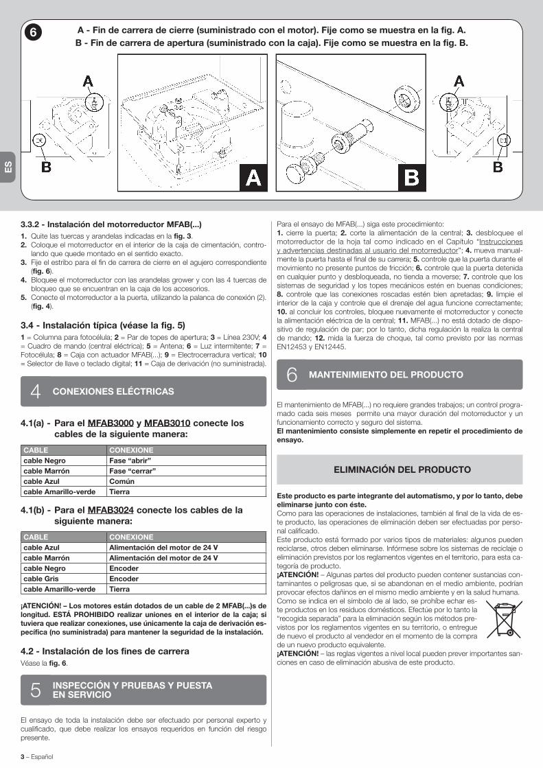
3.3.2 - Instalación del motorreductor MFAB(...)1. Quite las tuercas y arandelas indicadas en la fig. 3.2. Coloque el motorreductor en el interior de la caja de cimentación, contro-
lando que quede montado en el sentido exacto.3. Fije el estribo para el fin de carrera de cierre en el agujero correspondiente
(fig. 6).4. Bloquee el motorreductor con las arandelas grower y con las 4 tuercas de
bloqueo que se encuentran en la caja de los accesorios.5. Conecte el motorreductor a la puerta, utilizando la palanca de conexión (2).
(fig. 4).
3.4 - Instalación típica (véase la fig. 5)1 = Columna para fotocélula; 2 = Par de topes de apertura; 3 = Línea 230V; 4 = Cuadro de mando (central eléctrica); 5 = Antena; 6 = Luz intermitente; 7 = Fotocélula; 8 = Caja con actuador MFAB(...); 9 = Electrocerradura vertical; 10 = Selector de llave o teclado digital; 11 = Caja de derivación (no suministrada).
CONEXIONES ELÉCTRICAS44.1(a) - Para el MFAB3000 y MFAB3010 conecte los
cables de la siguiente manera:
CABLE CONEXIONEcable Negro Fase “abrir”cable Marrón Fase “cerrar”cable Azul Comúncable Amarillo-verde Tierra
4.1(b) - Para el MFAB3024 conecte los cables de la siguiente manera:
CABLE CONEXIONEcable Azul Alimentación del motor de 24 Vcable Marrón Alimentación del motor de 24 Vcable Negro Encodercable Gris Encodercable Amarillo-verde Tierra
¡ATENCIÓN! – Los motores están dotados de un cable de 2 MFAB(...)s de longitud. ESTÁ PROHIBIDO realizar uniones en el interior de la caja; si tuviera que realizar conexiones, use únicamente la caja de derivación es-pecífica (no suministrada) para mantener la seguridad de la instalación.
4.2 - Instalación de los fines de carreraVéase la fig. 6.
INSPECCIÓN Y PRUEBAS Y PUESTAEN SERVICIO5
El ensayo de toda la instalación debe ser efectuado por personal experto y cualificado, que debe realizar los ensayos requeridos en función del riesgo presente.
Para el ensayo de MFAB(...) siga este procedimiento:1. cierre la puerta; 2. corte la alimentación de la central; 3. desbloquee el motorreductor de la hoja tal como indicado en el Capítulo “Instrucciones y advertencias destinadas al usuario del motorreductor”; 4. mueva manual-mente la puerta hasta el final de su carrera; 5. controle que la puerta durante el movimiento no presente puntos de fricción; 6. controle que la puerta detenida en cualquier punto y desbloqueada, no tienda a moverse; 7. controle que los sistemas de seguridad y los topes mecánicos estén en buenas condiciones; 8. controle que las conexiones roscadas estén bien apretadas; 9. limpie el interior de la caja y controle que el drenaje del agua funcione correctamente; 10. al concluir los controles, bloquee nuevamente el motorreductor y conecte la alimentación eléctrica de la central; 11. MFAB(...) no está dotado de dispo-sitivo de regulación de par; por lo tanto, dicha regulación la realiza la central de mando; 12. mida la fuerza de choque, tal como previsto por las normas EN12453 y EN12445.
MANTENIMIENTO DEL PRODUCTO6El mantenimiento de MFAB(...) no requiere grandes trabajos; un control progra-mado cada seis meses permite una mayor duración del motorreductor y un funcionamiento correcto y seguro del sistema.El mantenimiento consiste simplemente en repetir el procedimiento de ensayo.
ELIMINACIÓN DEL PRODUCTO
Este producto es parte integrante del automatismo, y por lo tanto, debe eliminarse junto con éste.Como para las operaciones de instalaciones, también al final de la vida de es-te producto, las operaciones de eliminación deben ser efectuadas por perso-nal calificado.Este producto está formado por varios tipos de materiales: algunos pueden reciclarse, otros deben eliminarse. Infórmese sobre los sistemas de reciclaje o eliminación previstos por los reglamentos vigentes en el territorio, para esta ca-tegoría de producto.¡ATENCIÓN! – Algunas partes del producto pueden contener sustancias con-taminantes o peligrosas que, si se abandonan en el medio ambiente, podrían provocar efectos dañinos en el mismo medio ambiente y en la salud humana.Como se indica en el símbolo de al lado, se prohíbe echar es-te productos en los residuos domésticos. Efectúe por lo tanto la “recogida separada” para la eliminación según los métodos pre-vistos por los reglamentos vigentes en su territorio, o entregue de nuevo el producto al vendedor en el momento de la compra de un nuevo producto equivalente.¡ATENCIÓN! – las reglas vigentes a nivel local pueden prever importantes san-ciones en caso de eliminación abusiva de este producto.
6 A - Fin de carrera de cierre (suministrado con el motor). Fije como se muestra en la fig. A.B - Fin de carrera de apertura (suministrado con la caja). Fije como se muestra en la fig. B.
ES
Español – 4
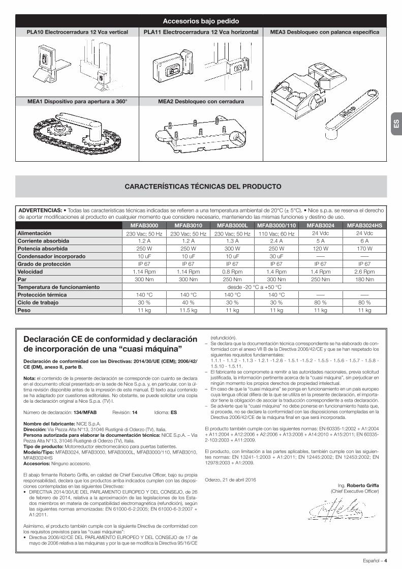
ADVERTENCIAS: • Todas las características técnicas indicadas se refieren a una temperatura ambiental de 20°C (± 5°C). • Nice s.p.a. se reserva el derecho de aportar modificaciones al producto en cualquier momento que considere necesario, manteniendo las mismas funciones y destino de uso.
MFAB3000 MFAB3010 MFAB3000L MFAB3000/110 MFAB3024 MFAB3024HSAlimentación 230 Vac; 50 Hz 230 Vac; 50 Hz 230 Vac; 50 Hz 110 Vac; 60 Hz 24 Vdc 24 VdcCorriente absorbida 1.2 A 1.2 A 1.3 A 2.4 A 5 A 6 APotencia absorbida 250 W 250 W 300 W 250 W 120 W 170 WCondensador incorporado 10 uF 10 uF 10 uF 30 uF ––– –––Grado de protección IP 67 IP 67 IP 67 IP 67 IP 67 IP 67Velocidad 1.14 Rpm 1.14 Rpm 0.8 Rpm 1.4 Rpm 1.4 Rpm 2.6 RpmPar 300 Nm 300 Nm 250 Nm 300 Nm 250 Nm 180 NmTemperatura de funcionamiento desde -20 °C a +50 °CProtección térmica 140 °C 140 °C 140 °C 140 °C ––– –––Ciclo de trabajo 30 % 40 % 30 % 30 % 80 % 80 %Peso 11 kg 11.5 kg 11 kg 11 kg 11 kg 11 kg
CARACTERÍSTICAS TÉCNICAS DEL PRODUCTO
Accesorios bajo pedido
PLA10 Electrocerradura 12 Vca vertical PLA11 Electrocerradura 12 Vca horizontal MEA3 Desbloqueo con palanca específica
MEA1 Dispositivo para apertura a 360° MEA2 Desbloqueo con cerradura
Declaración CE de conformidad y declaración de incorporación de una “cuasi máquina”Declaración de conformidad con las Directivas: 2014/30/UE (CEM); 2006/42/CE (DM), anexo II, parte B.
Nota: el contenido de la presente declaración se corresponde con cuanto se declara en el documento oficial presentado en la sede de Nice S.p.a. y, en particular, con la úl-tima revisión disponible antes de la impresión de este manual. El texto aquí contenido se ha adaptado por cuestiones editoriales. No obstante, se puede solicitar una copia de la declaración original a Nice S.p.a. (TV) I.
Número de declaración: 134/MFAB Revisión: 14 Idioma: ES
Nombre del fabricante: NICE S.p.A.Dirección: Via Pezza Alta N°13, 31046 Rustignè di Oderzo (TV), Italia.Persona autorizada para elaborar la documentación técnica: NICE S.p.A. – Via Pezza Alta N°13, 31046 Rustignè di Oderzo (TV), Italia.Tipo de producto: Motorreductor electromecánico para puertas batientes.Modelo/Tipo: MFAB3024, MFAB3000, MFAB3000L, MFAB3000/110, MFAB3010, MFAB3024HSAccesorios: Ninguno accesorio.
El abajo firmante Roberto Griffa, en calidad de Chief Executive Officer, bajo su propia responsabilidad, declara que los productos arriba indicados cumplen con las disposi-ciones contempladas en las siguientes Directivas:• DIRECTIVA 2014/30/UE DEL PARLAMENTO EUROPEO Y DEL CONSEJO, de 26
de febrero de 2014, relativa a la aproximación de las legislaciones de los Esta-dos miembros en materia de compatibilidad electromagnética (refundición), según las siguientes normas armonizadas: EN 61000-6-2:2005; EN 61000-6-3:2007 + A1:2011.
Asimismo, el producto también cumple con la siguiente Directiva de conformidad con los requisitos previstos para las “cuasi máquinas”:• Directiva 2006/42/CE DEL PARLAMENTO EUROPEO Y DEL CONSEJO de 17 de
mayo de 2006 relativa a las máquinas y por la que se modifica la Directiva 95/16/CE
(refundición).– Se declara que la documentación técnica correspondiente se ha elaborado de con-
formidad con el anexo VII B de la Directiva 2006/42/CE y que se han respetado los siguientes requisitos fundamentales:
1.1.1 - 1.1.2 - 1.1.3 - 1.2.1 -1.2.6 - 1.5.1 -1.5.2 - 1.5.5 - 1.5.6 - 1.5.7 - 1.5.8 - 1.5.10 - 1.5.11.
– El fabricante se compromete a remitir a las autoridades nacionales, previa solicitud justificada, la información pertinente acerca de la “cuasi máquina”, sin perjudicar en ningún momento los propios derechos de propiedad intelectual.
– En caso de que la “cuasi máquina” se ponga en funcionamiento en un país europeo cuya lengua oficial difiera de la que se utiliza en la presente declaración, el importa-dor tiene la obligación de asociar la traducción correspondiente a esta declaración.
– Se advierte que la “cuasi máquina” no debe ponerse en funcionamiento hasta que, si procede, no se declare la conformidad con las disposiciones contempladas en la Directiva 2006/42/CE de la máquina final en que será incorporada.
El producto también cumple con las siguientes normas: EN 60335-1:2002 + A1:2004 + A11:2004 + A12:2006 + A2:2006 + A13:2008 + A14:2010 + A15:2011; EN 60335-2-103:2003 + A11:2009.
El producto, con limitación a las partes aplicables, también cumple con las siguien-tes normas: EN 13241-1:2003 + A1:2011; EN 12445:2002; EN 12453:2002; EN 12978:2003 + A1:2009.
Oderzo, 21 de abril 2016Ing. Roberto Griffa
(Chief Executive Officer)
DE
1 – Deutsch
ALLGEMEINE SICHERHEITSHINWEISE UND VORSICHTSMASSNAHMEN1
ALLGEMEINE HINWEISE
• ACHTUNG! - Sicherheitsrelevante Anweisungen. Alle Anwei-sungen strikt einhalten. Unkorrekte Installationen können schwerwiegende Schäden verursachen.
• ACHTUNG! - Sicherheitsrelevante Anweisungen. Damit die Si-cherheit von Personen gewährleistet ist, die folgenden Anwei-sungen einhalten. Die vorliegende Anleitung gut aufbewahren.
• Bevor Sie mit der Installation beginnen, sollten Sie unbedingt die „Technischen Eigenschaften des Produkts“ in dieser Anleitung prü-fen, insbesondere ob das vorliegende Produkt zur Automatisie-rung Ihres gesteuerten Tors oder Rollladens geeignet ist. Das Gerät NICHT installieren, wenn es nicht dafür geeignet ist.
• Das Gerät darf erst verwendet werden, nachdem es wie im Ab-schnitt „Abnahme und Inbetriebnahme“ beschrieben in Betrieb ge-nommen wurde.
• ACHTUNG! - Gemäß der neuesten europäischen Gesetzge-bung muss die Realisierung einer Automatisierung unter Be-achtung der von der geltenden Maschinenrichtlinie vorgese-henen harmonisierten Normen erfolgen, die es erlauben, eine Erklärung über die angenommene Konformität der Automati-sierung auszustellen. Unter Beachtung dessen dürfen alle Ar-beiten zum Anschluss an das Stromnetz, zur Abnahme, Inbe-triebsetzung und Wartung der Vorrichtung nur von einem qua-lifizierten und kompetenten Fachmann ausgeführt werden.
• Vor der Installation des Geräts ist sicherzustellen, dass das gesam-te Material in technischem einwandfreiem Zustand und für den Ein-satzzweck geeignet ist.
• ACHTUNG! - Um alle Gefahren im Zusammenhang mit einer un-vorhergesehenen Rücksetzung der Temperatursicherung zu verhindern, darf dieses Gerät nicht über eine externe Schalt-vorrichtung (z. B. eine Zeitschaltuhr) versorgt oder an einen Stromkreis angeschlossen werden, der regelmäßig ein- oder ausgeschaltet wird.
• Die Stromversorgung der Anlage muss über eine Trennvorrichtung (nicht im Lieferumfang enthalten) ausgeführt sein, deren Öffnungs-abstand der Kontakte eine vollständige Unterbrechung gemäß Über-spannungskategorie III garantiert.
• Das Produkt bei der Installation vorsichtig handhaben und Quet-schungen, Stöße, Herunterfallen sowie den Kontakt mit Flüssigkeiten jeder Art vermeiden. Das Produkt nicht in der Nähe von Wärmequel-len positionieren und es keinen offenen Flammen aussetzen. All diese Handlungen können das Produkt beschädigen oder Ursache für Stö-rungen oder Gefahrensituationen sein. In diesen Fällen die Installation unverzüglich abbrechen und den Kundendienst einschalten.
• Der Hersteller haftet nicht für Vermögens-, Personen- oder Sach-schäden, die durch Nichtbeachtung der Montageanweisungen ent-stehen. In diesen Fällen ist die Garantie für Materialfehler ausge-schlossen.
• Der A-bewertete Schalldruckpegel ist geringer als 70 dB(A).• Das Produkt vor jeder Arbeit an der Anlage (Wartung, Reinigung) im-
mer von der Stromversorgung abtrennen.• Prüfen Sie die Anlage regelmäßig auf eventuelle Ungleichgewichte,
Abnutzungserscheinungen und Schäden insbesondere von Kabeln, Federn und Halterungen. Verwenden Sie das Gerät nicht, wenn eine Reparatur oder Einstellung erforderlich ist, da eine unkorrekte Instal-lation oder ein nicht ordnungsgemäßer Gewichtsausgleich der Auto-matisierung.
• Das Verpackungsmaterial des Produkts muss entsprechend den einschlägigen Umweltschutzvorschriften entsorgt werden.
• Halten Sie alle anwesenden Personen von der Automatisierung fern, wenn diese über die Steuerelemente bewegt wird.
• Während der Ausführung der Bewegung die Automatisierung kon-trollieren und Personen solange fernhalten, bis die Bewegung ab-
geschlossen ist.• Betätigen Sie das Produkt nicht, wenn in der Nähe Personen an der
Automatisierung arbeiten; trennen Sie die Vorrichtung vom Strom-netz, bevor solche Arbeiten ausgeführt werden.
• Wenn das Netzkabel beschädigt ist, muss es vom Hersteller, vom technischen Kundendienst oder von einer Person mit einer ähnli-chen Qualifikation ersetzt werden, um so jeder Gefahr vorzubeugen.
INSTALLATIONSHINWEISE
• Vor dem Einbau des Antriebsmotors sicherstellen, dass alle mecha-nischen Komponenten in einem technisch einwandfreien Zustand sind, sich korrekt im Gleichgewicht befinden und die Automatisie-rung vorschriftsgemäß bedient werden kann.
• Falls das zu automatisierende Tor mit einem Fußgängerzugang aus-gestattet ist, wird es notwendig, an der Anlage ein Kontrollsystem zu installieren, das die Motorfunktion blockiert, wenn der Eingang für Fußgänger offen steht.
• Sicherstellen, dass die Antriebskomponenten einen ausreichenden Abstand zu den Bewegungsteilen haben und nicht die Sicht ver-sperren. Falls kein Wahlschalter verwendet wird, müssen die An-triebskomponenten in einer Höhe von mindestens 1,5 m montiert werden und dürfen nicht zugänglich sein.
• Jede Form des Einklemmens zwischen sich bewegenden und festen Teilen ist bei den Bewegungen vorherzusehen und zu vermeiden.
• Bringen Sie das Etikett für die Bedienung von Hand dauerhaft in der Nähe des Elements an, das die Bewegung selbst erlaubt.
• Nach dem Einbau des Antriebsmotors sicherstellen, dass der ge-samte Mechanismus, das Schutzsystem und die manuellen Bedien-vorgänge ordnungsgemäß funktionieren.
BESCHREIBUNG DES PRODUKTS UND BESTIM-MUNGSGEMÄSSER GEBRAUCH2
MFAB(...) ist ein Toröffner für die Automatisierung eines ein- oder zweiteiligen Drehtors. ACHTUNG! – Jeder andere Gebrauch, der anders ist als oben beschrieben und unter anderen Bedingungen als in der vorliegenden Anleitung vorgesehen ist unzulässig.
MFAB(...) funktioniert mit elektrischer Energie; bei Stromausfall kann der Tor-öffner mit den speziellen Schlüsseln entriegelt werden; danach kann man die Torflügel von Hand bewegen.
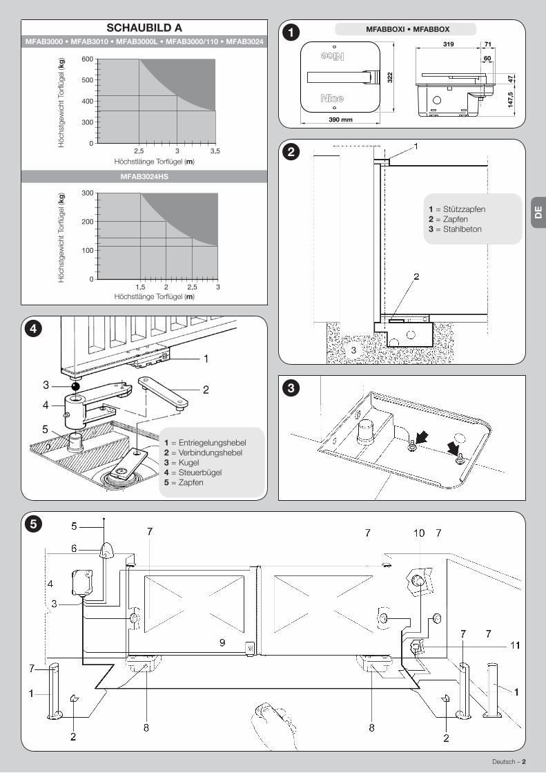
INSTALLATION33.1 - VorprüfungenVor der Installation ist zu prüfen, ob sich die Torstruktur eignet, anders gesagt, ob sie mit den gültigen Vorschriften konform ist. Insbesondere prüfen, ob: • das Tor in Schließung sowie in Öffnung keine Reibungen aufweist; • das Tor gut ausgeglichen ist. Das heißt, dass es sich nicht bewegen darf, wenn es in beliebiger Stellung stillsteht; • das Tor einen leisen und regulären Lauf hat; • der Befestigungsbereich des Toröffners eine einfache und sichere Bewegung von Hand ermöglicht.; • die Verpackung unbeschädigt ist; • der Befestigungs-bereich dem Platzbedarf des Kastens entspricht (Abb.1); • einen Endanschlag in Schließung und möglichst auch in Öffnung vorsehen.
ACHTUNG! – Es wird daran erinnert, dass MFAB(...) ein bereits effizientes und sicheres Tor (ein- oder zweiteilig) motorisiert; MFAB(...) kann Proble-me aufgrund falscher Installation oder schlechter Wartung nicht lösen.
3.2 - EinsatzgrenzenForm und Höhe des Tors (z.B. ausgefacht) sowie starker Wind können die Werte in der Schaubild A gezeigten.Anmerkung – Sollte jeder Torflügel länger als 2,5 m sein, wird der Einbau eines Elektroschlosses (PLA10 oder PLA11) empfohlen.
3.3 - Befestigung
3.3.1 - Gesamtabmessungen und Positionieren des Funda-mentkastens
1. Je nach den Gesamtabmessungen eine Ausgrabung für den Fundament-kasten ausführen; eine gute Drainage vorsehen, um Wasserrückstau zu vermeiden.
2. Das Zubehör für den Endschalter in Öffnung am Fundamentkasten be-festigen; die genau befolgen Anweisungen in der Abb. 6, um eine falsche
DEUTSCHAus dem Italienischen übersetzte Anleitung
DE
Deutsch – 2
1 = Entriegelungshebel2 = Verbindungshebel3 = Kugel4 = Steuerbügel5 = Zapfen
4
3
SCHAUBILD AMFAB3000 • MFAB3010 • MFAB3000L • MFAB3000/110 • MFAB3024
2,5 3 3,50
300
400
500
600
Höchstlänge Torflügel (m)
Höc
hstg
ewic
ht T
orflü
gel (
kg)
MFAB3024HS
1,5 2,52 30
100
200
300
Höchstlänge Torflügel (m)
Höc
hstg
ewic
ht T
orflü
gel (
kg)
5
1 = Stützzapfen2 = Zapfen3 = Stahlbeton
2
3
147,
547
71319
60
322
390 mm
1 MFABBOXI • MFABBOX
3 – Deutsch
DE
Befestigung zu vermeiden.3. Den Fundamentkasten in der Ausgrabung anbringen; der Zapfen muss mit
der Achse des Scharniers fluchten (Abb. 2).4. Eine Leitung für die Elektrokabel und eine für die Drainage vorsehen.5. Den Fundamentkasten im Beton versenken, genau nivellieren und die Höhe
beachten.6. Den Steuerbüge auf den Zapfen des Kastens stecken; die mitgelieferte Ku-
gel zwischenlegen.7. Den Torflügel auf den Entriegelungshebel stützen und fest anschweißen.8. Mit der speziellen Fettbüchse einfetten.
3.3.2 - Installation des Toröffners MFAB(...)1. Entfernen Sie die Muttern und Unterlegscheiben, in Abb. 3 dargestellt.2. Den Toröffner im Fundamentkasten anbringen; sicher stellen, dass er im rich-
tigen Sinn eingebaut wird.3. Den Bügel für den Endschalter in Schließung in der dazu vorgesehenen Boh-
rung befestigen (Abb 6).4. Den Toröffner mit den Grower-Unterlegscheiben und den 4 selbstsperren-
den Muttern in der Zubehörschachtel befestigen.5. Den Toröffner mit dem Verbindungsbügel (2) mit dem Tor verbinden (Abb. 4).
3.4 - Typische Anlage (siehe Abb. 5)1 = Standsäule für Photozelle; 2 = Paar Endanschläge in Öffnung; 3 = 230V Linie; 4 = Steuerung; 5 = Antenne; 6 = Blinkleuchte; 7 = Photozelle; 8 = Fun-damentkasten mit Toröffner MFAB(...); 9 = Elektroschloss, vertikal; 10 = Schlüs-seltaster oder digitales Codeschloss; 11 = Abzweigkasten (nicht mitgeliefert).
ELEKTRISCHE VERBINDUNGEN44.1(a) - Für MFAB3000 und MFAB3010, die Kabel
wie folgt anschließen:
DRAHT VERBINDUNGSchwarzer Draht Phase „öffnet“Brauner Draht Phase „schließt“Blauer Draht GemeinsamGelb-grüner Draht Erde
4.1(b) - Für MFAB3024, die Kabel wie folgt anschließen:
DRAHT VERBINDUNGBlauer Draht Motor-Stromversorgung 24 VBrauner Draht Motor-Stromversorgung 24 VSchwarzer Draht EncoderGrauer Draht EncoderGelb-grüner Draht Erde
ACHTUNG! – Die Motoren verfügen über ein 2m langes Kabel. ES IST VERBOTEN, Kabel im Kasten zusammen zu fügen; für eventuel-le Verbindungen nur den speziellen Abzweigkasten (nicht mitgeliefert) verwenden, um den Sicherheitsgrad der Anlage beizubehalten.
4.2 - Positionieren der EndschalterSiehe Abb. 6.
PRÜFUNG UND INBETRIEBNAHME5Die Abnahme der gesamten Anlage muss von erfahrenem Fachpersonal mit Tests ausgeführt werden, die dem vorhandenen Risiko entsprechen müssen. Für die Abnahme von MFAB(...) wie folgt vorgehen:1. das Tor schließen; 2. die Versorgung zur Steuerung abschalten; 3. den Toröff-ner vom Torflügel entriegeln, wie in Kapitel “Anweisungen und Hinweise für den Benutzer des Toröffners” gezeigt; 4. das Tor von Hand ganz öffnen; 5. prüfen, dass das Tor während der Bewegung nicht durch Reibung behindert wird; 6. prüfen, dass sich das Tor nicht bewegt, wenn es in beliebiger Stellung stillsteht; 7. prüfen, dass sich die Sicherheitssysteme und die mechanischen Anschläge in gutem Zustand befinden; 8. prüfen, dass die Schraubverbindungen fest an-gezogen sind; 9. das Kasteninnere reinigen und prüfen, ob der Wasserabfluss korrekt funktioniert; 10. den Toröffner nach Beendigung der Überprüfungen wieder verriegeln und die Steuerung versorgen; 11. MFAB(...) hat keine Drehmo-mentregelung, diese Regelung ist daher der Steuerung anvertraut; 12. die Auf-prallkraft messen, wie von den Normen EN12453 und EN12445 vorgesehen.
WARTUNG DES PRODUKTS6Für die Wartung von MFAB(...) sind keine besonderen Maßnahmen erforderlich, jedoch gewährleistet eine programmierte Kontrolle mindestens alle sechs Mo-nate eine längere Lebensdauer des Toröffners und den korrekten und sicheren Betrieb des Systems.Die Wartung besteht einfach aus der Wiederholung des Abnahmever-fahrens.
ENTSORGUNG DES PRODUKTS
Dieses Produkt ist Teil der Antriebsautomatik und ist daher mit dieser zu entsorgen.Wie die Installationsverfahren ist auch die Verschrottung am Lebensende die-ses Produkts von Fachpersonal vorzunehmen.Dieses Produkt besteht aus verschiedenen Materialtypen: Einige können recy-celt werden, andere sind zu entsorgen. Informieren Sie sich bitte über die Re-cycling- oder Entsorgungssysteme, die von den in Ihrem Land geltenden Be-stimmungen für diese Produktkategorie vorgesehen sind.ACHTUNG! – Einige Teile des Produkts können Schad- oder Gefahrenstoffe enthalten, die bei Zerstreuung in der Umwelt schädliche Auswirkungen auf die Umwelt und auf die menschliche Gesundheit haben könnten.Wie vom seitlichen Symbol angezeigt, ist es verboten, dieses Produkt in den Hausmüll zu werfen. Zur Entsorgung ist daher die “getrennte Müllsammlung” nach den Methoden vorzunehmen, die von den in Ihrem Land geltenden Bestimmungen vorgesehen sind. Das Produkt kann beim Kauf eines neuen gleichwertigen Produkts auch an den Händler zurückgegeben werden.ACHTUNG! – Die auf örtlicher Ebene geltenden Bestimmungen können im Fall einer rechtswidrigen Entsorgung dieses Produkts schwere Strafen vorsehen.
6 A - Endschalter in Schließung (mit dem Motor geliefert). Wie auf der Abb. A gezeigt befestigen.B - Endschalter in Öffnung (mit dem Kasten geliefert). Wie auf der Abb. B gezeigt befestigen.

DE
Deutsch – 4
HINWEISE: • Alle hier wiedergegebenen technischen Merkmale beziehen sind auf eine Umgebungstemperatur von 20°C (± 5°C). • Die Firma Nice S.p.a. behält sich das Recht vor, jederzeit Änderungen am Produkt vorzunehmen, falls sie es für notwendig hält, wobei jedoch dieselbe Funktionstüchtigkeit und derselben Bestimmungszweck beibehalten wird.
MFAB3000 MFAB3010 MFAB3000L MFAB3000/110 MFAB3024 MFAB3024HSVersorgung 230 Vac; 50 Hz 230 Vac; 50 Hz 230 Vac; 50 Hz 110 Vac; 60 Hz 24 Vdc 24 VdcStromaufnahme 1.2 A 1.2 A 1.3 A 2.4 A 5 A 6 ALeistungsaufnahme 250 W 250 W 300 W 250 W 120 W 170 WEingebauter Kondensator 10 uF 10 uF 10 uF 30 uF ––– –––Schutzart IP 67 IP 67 IP 67 IP 67 IP 67 IP 67Geschwindigkeit 1.14 Rpm 1.14 Rpm 0.8 Rpm 1.4 Rpm 1.4 Rpm 2.6 RpmDrehmoment 300 Nm 300 Nm 250 Nm 300 Nm 250 Nm 180 NmBetriebstemperatur -20 °C bis +50 °CWärmeschutz 140 °C 140 °C 140 °C 140 °C ––– –––Arbeitszyklus 30 % 40 % 30 % 30 % 80 % 80 %Gewicht 11 kg 11.5 kg 11 kg 11 kg 11 kg 11 kg
TECHNISCHE MERKMALE DES PRODUKTS
Sonderzubehör
PLA10 12Vac Elektroschloss, vertikal PLA11 12Vac Elektroschloss, horizontal MEA3 Entriegelung mit speziellem Hebel
MEA1 Vorrichtung für 360° Öffnung MEA2 Entriegelung mit Schloss
CE-Konformitätserklärung und Einbauerklä-rung der „unvollständigen Maschine”Erklärung in Übereinstimmung mit den Richtlinien: 2014/30/UE (EMV); 2006/42/EG (MD) Anlage II, Teil B.
Anmerkung - Der Inhalt dieser Erklärung entspricht den Angaben im offiziellen Doku-ment, das im Sitz der Nice S.p.A. hinterlegt ist und der letzten verfügbaren Revision vor dem Druck dieser Anleitung. Dieser Text wurde aus redaktionellen Gründen ange-passt. Die Kopie der Original-Erklärung kann bei der Firma Nice S.p.A. (TV) I. ange-fordert werden.
Nummer der Erklärung: 134/MFAB Revision: 14 Sprache: DE
Name des Herstellers: NICE s.p.a.Adresse: Via Pezza Alta N°13, 31046 Rustignè di Oderzo (TV) Italy.Bevollmächtigte Person zum Zusammenstellen der technischen Unterlagen: NICE s.p.a. – Via Pezza Alta N°13, 31046 Rustignè di Oderzo (TV) ItalyArt des Produkts: Elektromechanisches Getriebe für Drehtore.Modell / Typ: MFAB3024, MFAB3000, MFAB3000L, MFAB3000/110, MFAB3010, MFAB3024HSZubehör: Kein Zubehör.
Der Unterzeichnende Roberto Griffa, in seiner Funktion als Chief Executive Officer, er-klärt auf eigene Verantwortung, dass die oben genannten Produkte den Bestimmun-gen entsprechen, die in folgenden Richtlinien enthalten sind:• RICHTLINIE 2014/30/UE DES EUROPÄISCHEN PARLAMENTS UND DES RATES
vom 26. Februar 2014 zur Angleichung der Rechtsvorschriften der Mitgliedsstaaten über die elektromagnetische Verträglichkeit (Überarbeitung), gemäß den folgenden harmonisierten Normen: EN 61000-6-2:2005; EN 61000-6-3:2007 + A1:2011.
Außerdem entspricht das Produkt folgender Richtlinie, entsprechend der vorgesehe-nen Anforderungen für die „unvollständigen Maschinen”:• Richtlinie 2006/42/EG DES EUROPÄISCHEN PARLAMENTS UND DES RATES
vom 17. Mai 2006 über Maschinen, welche die Richtlinie 95/16/EG ändert (Überar-beitung).
– Hiermit wird erklärt, dass die entsprechenden technischen Unterlagen in Überein-stimmung mit Anlage VII B der Richtlinie 2006/42/EG zusammengestellt und die fol-genden wesentlichen Anforderungen eingehalten wurden:
1.1.1 - 1.1.2 - 1.1.3 - 1.2.1 -1.2.6 - 1.5.1 -1.5.2 - 1.5.5 - 1.5.6 - 1.5.7 - 1.5.8 - 1.5.10 - 1.5.11.
– Der Hersteller verpflichtet sich, die Informationen über die „unvollständige Maschi-ne” auf Verlangen an die nationalen Behörden weiterzuleiten, wobei die eignen Rechte des geistigen Eigentums beibehalten werden.
– Wenn die „unvollständige Maschine” in einem europäischen Land in Betrieb ge-nommen wird, deren offizielle Sprache nicht der in dieser Erklärung entspricht, ist der Importeur verpflichtet, dieser Erklärung die entsprechende Übersetzung beizu-legen.
– Wir weisen darauf hin, dass die „unvollständige Maschine” erst dann in Betrieb ge-nommen werden darf, wenn gegebenenfalls festgestellt wurde, dass die Maschine, in die die unvollständige Maschine eingebaut werden soll, den Bestimmungen der Richtlinie 2006/42/EG entspricht.
Außerdem entspricht das Produkt folgenden Normen: EN 60335-1:2002 + A1:2004 + A11:2004 + A12:2006 + A2:2006 + A13:2008 + A14:2010 + A15:2011; EN 60335-2-103:2003 + A11:2009.
Das Produkt entspricht, auf die anwendbaren Teile begrenzt, folgenden Normen: EN 13241-1:2003 + A1:2011; EN 12445:2002; EN 12453:2002; EN 12978:2003 + A1:2009.
Oderzo, 21. April 2016Ing. Roberto Griffa
(Chief Executive Officer)

PL
1 – Polski
OGÓLNE UWAGI I ŚRODKI OSTROŻNOŚCI DOTYCZĄCE BEZPIECZEŃSTWA1
OGÓLNE OSTRZEŻENI
• UWAGA! - Ważne instrukcje bezpieczeństwa. Należy prze-strzegać wszystkich instrukcji, ponieważ nieprawidłowy mon-taż może być przyczyną poważnych szkód.
• UWAGA! - Ważne instrukcje bezpieczeństwa. W celu zapew-nienia bezpieczeństwa osób, należy przestrzegać niniejszych instrukcji. Należy zachować niniejszą instrukcję.
• Przed rozpoczęciemmontażu należy sprawdzić informacje na te-mat „Parametrów technicznych produktu” (zawartych w niniejszej in-strukcji),awszczególności,czyurządzeniejestprzystosowanedonapędzaniaposiadanegoprzezPaństwaurządzenia.Jeżeliproduktniejestodpowiedni,NIEnależywykonywaćmontażu.
• Nieużywaćurządzenia,jeślinieprzeprowadzonoproceduryodda-nia do eksploatacji, opisanej w rozdziale „Odbiór i przekazanie do eksploatacji”.
• UWAGA! - Według najnowszych, obowiązujących przepisów europejskich, wykonanie drzwi lub bramy automatycznej musi być zgodne z obowiązującą Dyrektywą Maszynową umożli-wiającą zadeklarowanie zgodności automatyki. W związku z tym, wszystkie czynności polegające na podłączeniu do sieci elektrycznej, wykonywaniu prób odbiorczych, przekazywaniu do eksploatacji i konserwacji urządzenia muszą być wykony-wane wyłącznie przez wykwalifikowanego i kompetentnego technika!
• Przedprzystąpieniemdomontażuproduktunależysprawdzić,czywszystkieelementyimateriałyprzeznaczonedoużyciaznajdująsięwidealnymstanieisąodpowiedniedoużycia.
• UWAGA! - W celu uniknięcia jakiegokolwiek zagrożenia na skutek przypadkowego uzbrojenia termicznego urządzenia odłączającego, nie należy zasilać tego urządzenia przy uży-ciu zewnętrznego urządzenia, jak zegar lub podłączać go do obwodu charakteryzującego się regularnym podłączaniem lub odłączaniem zasilania.
•Wsiecizasilającejinstalacjinależyprzygotowaćurządzenieodłącza-jące(nieznajdującesięnawyposażeniu),któregoodległośćpomię-dzystykamipodczasotwarciazapewniacałkowiteodłączeniewwa-runkachokreślonychprzezIIIkategoriąprzepięciową.
• Podczasmontażu, należy delikatnie obchodzić się z urządzeniem,chroniąc jeprzedzgnieceniem,uderzeniem,upadkiem lubkontak-tem z jakiegokolwiek rodzaju płynami. Nie umieszczać urządzeniawpobliżu źródeł ciepła i niewystawiać go na działanie otwartegoognia.Opisanepowyżejsytuacjemogądoprowadzićdouszkodzeniaurządzenia,byćprzyczynąnieprawidłowegodziałanialubzagrożeń.Jeżelidoszłobydoktórejśzopisanychsytuacji,należynatychmiastprzerwaćmontażizwrócićsięopomocdoSerwisuTechnicznego.
• Producentnieponosiodpowiedzialnościzaszkodymaterialne lubosobowepowstałewwynikunieprzestrzegania instrukcjimontażu.Wtakichprzypadkach,niemazastosowaniarękojmiazawadyma-terialne.
• Poziomciśnieniaakustycznegoemisji skorygowanegocharaktery-stykąAjestniższyod70dB(A).
• Przedwykonaniemdziałańnainstalacji(konserwacja,czyszczenie),należyzawszeodłączyćproduktodsiecizasilającej.
• Należywykonywaćokresoweprzeglądyinstalacji,awszczególnościprzewodów,sprężyn iwsporników,celemwykryciaewentualnegobrakuwyważenialuboznakzużycia,czyuszkodzeń.Nieużywaćwraziekoniecznościnaprawylubregulacji,ponieważobecnośćuste-reklubniewłaściwewyważenieautomatykimożeprowadzićdopo-ważnychobrażeń.
•Materiałopakowaniowypodlegautylizacjizgodniezlokalnymiprze-pisami.
•Osobytrzecieniepowinnysięznajdowaćwpobliżubramypodczasjejprzesuwaniaprzyużyciuelementówsterowniczych.
• Podczaswykonywaniamanewru, należy nadzorować automatykęizadbaćoto,abyinneosobyniezbliżałysiędourządzenia,ażdoczasuzakończeniaczynności.
• Niesterowaćautomatyką,jeżeliwjejpobliżuznajdująsięosobywy-konująceczynności;przedwykonaniemtychczynnościnależyodłą-czyćzasilanieelektryczne.
• Jeśli przewód zasilający jest uszkodzony, należy go wymienić naidentycznydostępnyuproducentalubwserwisietechnicznymlubuinnejosobyposiadającejporównywalnekwalifikacje,abyuniknąćjakiegokolwiek ryzyka.
OSTRZEŻENIA NA TEMAT MONTAŻU
• Przed zamontowaniem silnika, należy sprawdzić stan wszystkichczęścimechanicznych,odpowiedniewyważenieiupewnićsię,czymożliwejestprawidłowemanewrowanieautomatyką.
• Jeżelibramaprzeznaczonadozautomatyzowaniaposiadarównieżdrzwidlapieszych,należyprzygotowaćinstalacjęzsystememkon-trolnym,któryuniemożliwidziałaniesilnika,gdydrzwidlapieszychbędąotwarte.
• Upewnićsię,żeelementysterowniczeznajdująsięzdalaodczęściwruchu,umożliwiającwkażdymrazieichbezpośredniąwidoczność.Wrazieniestosowaniaprzełącznika,elementysterowniczenależymon-towaćwmiejscuniedostępnyminaminimalnejwysokości1,5m.
• Zapobiegać i unikać jakiegokolwiek uwięzienia między częściamistałymiiczęściamiwruchupodczaswykonywaniamanewrów.
• Umieścićnastałetabliczkęnatematręcznegomanewruwpobliżuelementuumożliwiającegowykonaniemanewru.
• Pozamontowaniusilnikanależysięupewnić,żeprawidłowofunk-cjonujemechanizm,systemochronyikażdymanewrręczny.
OPIS PRODUKTU I JEGO PRZEZNACZENIE2MFAB(...) jest siłownikiem przeznaczonym do automatyzacji jedno lub dwuskrzydłowejbramy.UWAGA! – Każde inne użytkowanie od powyżej opisa-nego i w warunkach innych od wskazanych w instrukcji jest zabronione.
MFAB(...) działa na energię elektryczną, gdy jest jej brak można odsprzęglićsiłownikwłaściwymkluczemiotworzyćręcznie.
MONTAŻ33.1 - Kontrola wstępnaPrzedprzejściemdoinstalowaniasprawdzićczystrukturajestwłaściwa,czyli,winnychsłowach,odpowiadaaktualnieobowiązującymnormomisprawdzićczy: • przy otwieraniu i zamykaniu bramy nie ma punktów nadmiernego tarcia; •bramajestwyważona,czylizatrzymanawjakimkolwiekpunkcienieporuszasię;•bramaporuszasięcichoipłynnie;•miejscegdziemabyćzamocowanysiłownikjestbezpieczneiodpowiedniedlapracymontera;•opakowaniejestwintegralnym;•Zwryfikować,czymiejscenazainstalowaniesiłownikajestod-powiednie dla wymiarów jego obudowy (rys 1);•posiadazderzakkrańcowyprzy zamykaniu jak i otwieraniu.
UWAGA! – Przypominamy, że MFAB(...) jest urządzeniem napędowym do bramy (jedno lub dwu skrzydłowej), wydajnym i pewnym, ale nie usuwa wad spowodowanych błędnym zainstalowaniem czy źle wyko-nanymi czynnościami konserwacyjnymi.
3.2 - Ograniczenia w użytkowaniuForma,wysokośćbramy(np.ślepa)iwarunkiklimatyczne(np.Silnywiatr)mo-gązmniejszyćnawetznaczniewartościwskazanewSchemat A.Adnotacja–Jeślikażdeskrzydłobramyjestdłuższeod2,5mzalecasięza-instalowania zamka elektrycznego (PLA10 lub PLA11).
3.3 - Przymocowanie
3.3.1 - Wymiary gabarytowe i wykonanie skrzynki fundamentowej
1. Napodstawiewymiarówgabarytowychwykopaćdołeknafundamenta(patrzparagraf4),zaplanowaćtakżekanałnaodpływwody.
POLSKIInstrukcja przetłumaczona z języka włoskiego
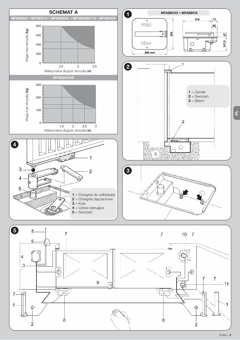
PL
Polski – 2
1=Dźwigniadoodblokady2=Dźwigniazłączeniowa3 = Kula4=Listwasterująca5=Sworzeń
4
3
SCHEMAT AMFAB3000 • MFAB3010 • MFAB3000L • MFAB3000/110 • MFAB3024
2,5 3 3,50
300
400
500
600
Maksymalnadlugośćskrzydla(m)
Wag
a m
ax s
krzy
dla
(kg
)
MFAB3024HS
1,5 2,52 30
100
200
300
Maksymalnadlugośćskrzydla(m)
Wag
a m
ax s
krzy
dla
(kg
)
5
1 = Zamek2=Sworzeń3 = Beton
2
3
147,
547
71319
60
322
390 mm
1 MFABBOXI • MFABBOX

PL
3 – Polski
2. Przymocowaćdoskrzyniczęśćnazderzakwedługinstrukcjiwskazanychnarys. 6,takabyniepopełnićbłęduprzymocowaniu.
3. Włożyćskrzynkędodołkutak,abysworzeńustawionybyłwliniizzamkiem(rys. 2).
4. Zaplanowaćprzejściekanalikanaprzewodyelektrycznei jedennadrenażwody.
5. Zalaćskrzynkęcementemisprawdzićustawieniepoziomnicą.6. Założyćnasworzeńskrzynilistwasterującaodblokadyuprzednimpodłoże-
niemodstręczonejkulki.7. Oprzećskrzydłobramynadźwigniodblokadyodblokadyprzyspawaćsolidnie.8. Posmarowaćsmarownicą.
3.3.2 - Instalowanie siłownika MFAB(...)1. Odkręcićnakrętkiipodkładkitakjakpokazanonarys. 3.2. Umieścićsiłownikwewnątrzskrzyni) i sprawdzić,abyzostałaonadobrze
włożona.3. Zainstalować zderzak wyłącznika krańcowego zamykania we właściwym
otworze (rys. 6).4. Zablokować siłownik z podkładkami grower i 4 nakrętki samoblokującej
znajdującesięwskrzynizakcesoriami.5. Połączyćzdźwigniązłączeniową(2)zsiłownikiemdobramy(rys. 4).
3.4 - Typowa instalacja (patrz rys. 5)1 = Kolumna na fotokomórki; 2 = Para zderzaków przy otwieraniu; 3 = Linia 230V; 4 = Tablica sterująca (centralka elektryczna);5 = Antena; 6 = Lampa ostrzegawcza; 7 = Fotokomórka; 8 = Skrzynka z aktuatorem MFAB(...); 9 = Elettrozamek pionowy; 10 = Selektor kluczowy lub klawiatura numeryczna; 11 = Skrzynka rozdzielcza (niedostarczona).
POŁĄCZENIA ELEKTRYCZNE44.1(a) - Dla MFAB3000 i MFAB3010 połączyć prze-
wody następująco:
PRZEWÓD POŁĄCZENIEprzewód Czarny Faza „otwiera”przewód Brązowy Faza „zamyka”przewód Niebieski Wspólnyprzewód Żółto-zielony Uziemienie
4.1(b) - Dla MFAB3024 połączyć przewody następująco:
PRZEWÓD POŁĄCZENIEprzewód Niebieski Zasilanie silnika 24 Vprzewód Brązowy Zasilanie silnika 24 Vprzewód Czarny Koderprzewód Szary Koderprzewód Żółto-zielony Uziemienie
UWAGA! – Silniki posiadają jedne 2 MFAB(...) wy przewód.ZABRANIA SIĘ wykonywać przedłużeń wewnątrz skrzyni, ewentualne połączenia wykonać w odpowiedniej skrzynce rozdzielczej (niedostar-czona), co jest bardo ważne dla utrzymania bezpieczeństwa instalacji.
4.2 - Ustawienie wyłączników granicznychPatrz rys. 6.
TEST KONTROLNY I URUCHOMIENIE5Próbyodbiorczecałejautomatykimusząbyćwykonaneprzezdoświadczonyiwykwalifikowanypersonel,któryweźmienasiebieodpowiedzialnośćzawyko-nanieswojejpracyiświadomyjestewentualnegoniebezpieczeństwa.OdbiórMFAB(...)wykonaćwedługponiższejprocedury:1.zamknąćbramę;2.odciąćzasilenieodcentrali;3.zablokowaćsiłowniktak,jakpodanowRozdział“Instrukcjeiostrzeżeniaprzeznaczonedlaużytkownikasiłownika”; 4.otworzyćcałkowicieręczniebramę;5.sprawdzić,czypodczasotwieranianiewystępujątarcia;6.sprawdzić,czypozatrzymaniuwjakimkol-wiekpunkciebramanieporuszysię;7.sprawdzić funkcjonowaniezabezpie-czeńistanzderzakówmechanicznych;8.sprawdzićczypołączeniasąściśnię-te do oporu; 9.wyczścićwnętrzeskrzyniisprawdzićczyspustwodyfunkcjo-nujeprawidłowo;10.powykonaniuwszystkichkontroliponowniezablokowaćsiłownikipodłączyćzasileniecentrali;11.MFAB(...)nieposiadaurządzeniadoregulacjimomentudlategoteżtakaregulacjazostaniewykonanaprzezcentra-lęsterującą;12.zmierzyćsiłęuderzeniawedługnormyEN12453iEN12445.
KONSERWACJA PRODUKTU6Siłownik MFAB(...) nie wymaga specjalnych czynności konserwacyjnych, aprzewidziana kontrola co sześć miesięcy gwarantuje dłuższą żywotność si-łownika i bezpieczne funkcjonowanie systemu.Czynności konserwacyjne polegają na powtórzeniu procedury prób odbiorczych.
LIKWIDACJA PRODUKTU
Ten produkt jest częścią integracyjną automatu i dlatego, musi być zli-kwidowany razem z nim.Takjakprzyczynnościachmontażowych,zarównopozużyciuproduktu,czyn-nościeliminacjimusząbyćwykonaneprzezwykwalifikowanypersonel.Produktskładasięzróżnychmateriałów:niektóremogąbyćodzyskiwane,in-nemusząbyćzlikwidowane.Dowiedzciesięosystemachodzyskiwanialubli-kwidacjiprzewidzianychwprawieobowiązującymnawaszymterytorium,dlatej kategorii produktu.Uwaga!–niektóreczęściproduktumogązawieraćsubstancjezanieczyszcza-jącelubniebezpieczne,którerozproszone,mogłybyzagrażaćśrodowiskuna-turalnemu i ludzkiemu zdrowiu.Jakwskazujesymbolobok,zabraniasięwyrzucaniaproduktudoodpadówdomowych.Należywykonać“selektywnązbiór-kęodpadów”dlalikwidacji,zgodniezmetodamiprzewidziany-miprzepisamiobowiązującyminawaszymterytoriumluboddaćproduktsprzedawcywmomenciezakupunowegorównoważ-nego produktu.Uwaga!–przepisyobowiązującenapoziomielokalnymmogąprzewidywaćpoważnekarywprzypadkunielegalnejlikwidacjitegoproduktu.
6 A - Wyłącznik krańcowy zamykania (dostarczony wraz z silnikiem). Przymocować tak, jak wskazano na rys. A.
B - Wyłącznik krańcowy otwieraniu (dostarczony wraz ze skrzynka). Przymocować tak, jak wskazano na rys. B.

PL
Polski – 4
OSTRZEŻENIE: •Wszystkieprzytoczonecechytechniczne,odnosząsiędotemperaturyotoczenia20°C(±5°C).•NiceS.p.a.zastrzegasobieprawodowprowadzeniazmianwkażdymmomencie,gdyuznazakonieczne,zachowująctąsamafunkcjonalnośćiużycie.
MFAB3000 MFAB3010 MFAB3000L MFAB3000/110 MFAB3024 MFAB3024HSZasilenie 230 Vac; 50 Hz 230 Vac; 50 Hz 230 Vac; 50 Hz 110 Vac; 60 Hz 24 Vdc 24 VdcPrąd absorbowany 1.2 A 1.2 A 1.3 A 2.4 A 5 A 6 AMoc absorbowana 250 W 250 W 300 W 250 W 120 W 170 WWbudowany kondensator 10 uF 10 uF 10 uF 30 uF ––– –––Stopie zabezpieczenia IP 67 IP 67 IP 67 IP 67 IP 67 IP 67Prądkość 1.14 Rpm 1.14 Rpm 0.8 Rpm 1.4 Rpm 1.4 Rpm 2.6 RpmMoment 300 Nm 300 Nm 250 Nm 300 Nm 250 Nm 180 NmTemperatura pracy od -20 °C do +50 °CTermo zabezpieczenie 140 °C 140 °C 140 °C 140 °C ––– –––Cykl pracy 30 % 40 % 30 % 30 % 80 % 80 %Waga 11 kg 11.5 kg 11 kg 11 kg 11 kg 11 kg
CECHY TECHNICZNE PRODUKTU
Akcesoria na życzenie
PLA10 Elettrozamek 12 Vca pionowy PLA11 Elettrozamek 12 Vca poziomy MEA3 Odblokada z dźwignią
MEA1 Urządzenie otwierające na 360° MEA2 Odblokada na zamek
Deklaracja zgodności CE i deklaracja włą-czenia maszyny nieukończonejDeklaracja zgodna z dyrektywami: 2014/30/UE (EMC); 2006/42/WE (MD) za-łącznik II, część B.
Uwaga-TreśćniniejszejdeklaracjijestzgodnazoficjalnądeklaracjązdeponowanąwsiedzibieNiceS.p.a.,awszczególnościznajnowsząwersjądostępnąprzedwy-drukowaniemniniejszegopodręcznika.Niniejszytekstzostałdostosowanypodkątemwydawniczym.KopięoryginalnejdeklaracjizgodnościmożnaotrzymaćodfirmyNiceS.p.a. (TV) I.
Numer deklaracji: 134/MFAB Weryfikacja: 14Język:PL
Nazwa producenta: NICE s.p.a.Adres: ViaPezzaAltaN°13,31046RustignèdiOderzo(TV),Włochy.Osoba upoważniona do sporządzenia dokumentacji technicznej: NICE s.p.a. – ViaPezzaAltaN°13,31046RustignèdiOderzo(TV),Włochy.Typ produktu: Siłownikelektromechanicznydobramskrzydłowych.Model/Typ: MFAB3024, MFAB3000, MFAB3000L, MFAB3000/110, MFAB3010, MFAB3024HSAkcesoria:Nieurządzenia.
Ja,niżejpodpisanyRobertoGriffa,jakoChiefExecutiveOfficerdeklarujęnawłasnąodpowiedzialność,żewyżejwymienioneproduktysązgodneznastępującymidyrek-tywami:• Dyrektywa PARLAMENTU EUROPEJSKIEGO I RADY 2014/30/UE z dnia 26 luty 2014r.wsprawieujednoliceniaprawodawstwapaństwczłonkowskichwzakresiezgodnościelektromagnetycznej(przekształcenie),zgodnieznastępującyminorma-mi zharmonizowanymi: EN 61000-6-2:2005; EN 61000-6-3:2007 + A1:2011.
Ponadtoproduktjestzgodnyznastępującądyrektywąwzakresiewymagańdotyczą-cychmaszynnieukończonych:• Dyrektywa PARLAMENTU EUROPEJSKIEGO I RADY NR 2006/42/WE z dnia 17 maja2006r.dotyczącamaszyn,zmieniającadyrektywę95/16/WE(przekształce-nie).
– Niżejpodpisanydeklaruje,żestosownadokumentacjatechnicznazostałasporzą-dzonazgodniezzałącznikiemVIIBdyrektywy2006/42/WEoraz,żespełnionezo-stałynastępującewymaganiapodstawowe:
1.1.1 - 1.1.2 - 1.1.3 - 1.2.1 -1.2.6 - 1.5.1 -1.5.2 - 1.5.5 - 1.5.6 - 1.5.7 - 1.5.8 - 1.5.10 - 1.5.11.
– Producentzobowiązujesiędoprzekazaniawładzomkrajowym,wodpowiedzinauzasadnionezapytanie,informacjidotyczącychmaszynynieukończonej,zachowu-jąccałkowicieswojeprawadowłasnościintelektualnej.
– Jeżelimaszynanieukończonaoddanazostaniedoeksploatacjiwkrajueuropej-skim,któregojęzykurzędowyjestinnyniżjęzykniniejszejdeklaracji,importermaobowiązekdołączyćdoniniejszejdeklaracjistosownetłumaczenie.
– Ostrzegamy,żemaszynynieukończonejnienależyuruchamiaćdoczasu,kiedyma-szynakońcowa,doktórejzostaniewłączona,nieuzyskadeklaracjizgodności(jeżeliwymagana,)zzałożeniamidyrektywy2006/42/WE.
Ponadtoproduktjestzgodnyznastępującyminormami:EN60335-1:2002+A1:2004+ A11:2004 + A12:2006 + A2:2006 + A13:2008 + A14:2010 + A15:2011; EN 60335-2-103:2003 + A11:2009.
Produkt jestzgodnyznastępującyminormami (wzakresiemającychzastosowa-nieczęści):EN13241-1:2003+A1:2011;EN12445:2002;EN12453:2002;EN12978:2003 + A1:2009.
Oderzo,dnia21kwiecień2016rokuInż.Roberto Griffa
(Chief Executive Officer)

NL
1 – Nederlands
ALGEMENE WAARSCHUWINGEN EN VOOR-ZORGSMAATREGELEN VOOR DE VEILIGHEID1
ALGEMENE WAARSCHUWINGEN
• LET OP! - Belangrijke aanwijzingen voor de veiligheid. Leef alle voorschriften na, want een niet correct uitgevoerde in-stallatie kan ernstige schade veroorzaken.
• LET OP! - Belangrijke aanwijzingen voor de veiligheid. Het is belangrijk dat deze instructies worden opgevolgd voor de vei-ligheid van personen. Bewaar deze instructies.
• Voordat u begint met de installatie dient u de “Technische kenmer-ken van het product” (in deze handleiding) te controleren, in het bij-zonder of dit product geschikt is voor uw geleide onderdeel. Als het product niet geschikt is, mag u NIET overgaan tot de installatie.
• Het product mag niet worden gebruikt voordat de inbedrijfstelling heeft plaatsgevonden zoals gespecificeerd in het hoofdstuk “Eind-test en inbedrijfstelling”.
• LET OP! - Volgens de meest recente Europese wetgeving moet het uitvoeren van een automatisering voldoen aan de geharmoniseerde normen van de geldende Machinerichtlijn, waarbij een verklaring van de conformiteit van de automatise-ring afgegeven kan worden. In verband hiermee moeten alle werkzaamheden in verband met de aansluiting op de elektri-sche voeding, de eindtest, de inbedrijfstelling en het onder-houd van het product uitsluitend worden uitgevoerd door een gekwalificeerde en deskundige monteur!
• Voordat u met de installatie van het product begint, dient u te con-troleren of al het te gebruiken materiaal in optimale staat en geschikt voor gebruik is.
• LET OP! - Om ieder risico op onvoorzien heropstarten van het thermische onderbrekingsmechanisme te vermijden, mag dit apparaat niet worden gevoed via een externe regelaar zoals een timer, noch worden aangesloten op een circuit dat regel-matig wordt in- of uitgeschakeld.
• U moet op het spanningsnet van de installatie een uitschakelappa-raat aansluiten (niet meegeleverd) met een openingsafstand tussen de contacten waarbij volledige uitschakeling mogelijk is bij de condi-ties die gelden voor overspanningscategorie III.
• Behandel het product tijdens de installatie met zorg en voorkom dat het wordt geplet, dat er tegen wordt gestoten, dat het valt of dat het in aanraking komt met welke vloeistoffen dan ook. Zet het product niet in de buurt van warmtebronnen en stel het niet bloot aan open vuur. Hierdoor kan het beschadigd worden, waardoor storingen of gevaarlijke situaties kunnen ontstaan. Als dit gebeurt, stopt u de in-stallatie onmiddellijk en wendt u zich tot de klantendienst.
• De fabrikant is niet aansprakelijk voor materiële schade, zowel aan personen als aan voorwerpen, die voortvloeit uit de niet-naleving van de montage-instructies. In die gevallen is enige garantie voor mate-riaalfouten uitgesloten.
• Het geluidsdrukniveau van de gemeten emissie A bedraagt minder dan 70 dB(A).
• Voordat u werkzaamheden aan de installatie uitvoert (onderhoud, reiniging), moet het product altijd worden losgekoppeld van de net-voeding.
• Controleer de installatie regelmatig. Controleer met name de kabels, de veren en de steunen om eventuele verstoringen van de balan-cering en tekenen van slijtage of beschadiging in een vroeg stadi-um op te merken. Gebruik het apparaat nooit als het gerepareerd of opnieuw afgesteld moet worden; een storing in de installatie of een niet-correcte balancering van de automatisering kan tot letsel leiden.
• Het verpakkingsmateriaal moet volgens de plaatselijk geldende voorschriften afgevoerd worden.
• Houd personen uit de buurt van de poort wanneer deze wordt be-wogen met behulp van de bedieningselementen.
• Controleer de automatisering tijdens het uitvoeren van de manoeuv-re en houd personen op enige afstand tot de beweging voltooid is.
• Bedien het product niet als er personen in de buurt zijn die werk-zaamheden op de automatisering uitvoeren; koppel de elektrische voeding los alvorens deze werkzaamheden te laten uitvoeren.
• Als de voedingskabel beschadigd is, moet deze worden vervangen door de fabrikant of door de technische ondersteuningsdienst, of in ieder geval door een monteur met een vergelijkbare kwalificatie om ieder risico uit te sluiten.
WAARSCHUWINGEN M.B.T. DE INSTALLATIE
• Controleer voordat u de bewegingsmotor installeert of alle mechani-sche onderdelen in goede staat zijn, volgens de regels gebalanceerd zijn en of de automatisering correct kan worden gemanoeuvreerd.
• Als het te automatiseren hek van een voetgangersdeur is voorzien, moet de installatie een controlesysteem krijgen, dat de werking van de motor blokkeert als de voetgangersdeur open is.
• Verzeker u ervan dat de bedieningselementen uit de buurt van de bewegende onderdelen worden gehouden, maar wel direct zicht op de poort geven. Tenzij u een schakelaar gebruikt, moeten de bedie-ningselementen op een hoogte van minimaal 1,5 m worden geïnstal-leerd en mogen ze niet toegankelijk zijn.
• Voorkom en vermijd elke vorm van blokkering tussen de bewegende en vaste onderdelen tijdens de bewegingen.
• Breng het etiket m.b.t. de handmatige bediening permanent aan in de buurt van het bedieningselement waarmee de handmatige bewe-ging wordt uitgevoerd.
• Verzeker u er na het installeren van de bewegingsmotor van dat het mechanisme, het beveiligingssysteem en alle bewegingen correct functioneren.
BESCHRIJVING VAN HET PRODUCT EN GEBRUIKSBESTEMMING2
MFAB(...) is een reductiemotor bestemd voor het automatiseren van een draaipoort met één of twee vleugels. LET OP! – Elke toepassing die afwijkt van wat hierboven beschreven is of plaatsvindt onder andere omstan-digheden dan in deze handleiding voorzien is, is verboden.
MFAB(...) werkt op elektrische energie; in geval van stroomuitval kan de re-ductiemotor met speciale sleutels ontgrendeld worden en kunnen de vleugels handmatig verplaatst worden.
INSTALLATIE33.1 - Controles voorafAlvorens met de installatie te beginnen dient u te verifiëren of de structuur daarvoor geschikt is, met andere woorden conform de geldende voorschriften.Verifieer met name de volgende zaken: • de poort vertoont geen punten waar wrijving bestaat, noch bij sluiting noch bij opening; • de poort is goed uitgebalanceerd is, d.w.z. de poort komt niet in beweging wanneer die op een willekeurige plaats tot stilstand is gebracht; • de poort loopt soepel en regelmatig; • de plaats van bevestiging voor de reductiemotor is gemakkelijk en veilig toegankelijk om de motor met de hand te bedienen; • de verpakking is intact; • controleer of de plaats van bevestiging met de buitenafmetingen van de kist (afb. 1) overeen komt; • zorg voor een stop bij sluiting en zo mogelijk ook bij opening.
LET OP! – Denk eraan dat MFAB(...) een poort (met één of twee vleu-gels) automatiseert die zelf goed moet werken en veilig is, maar dat MFAB(...) geen defecten opheft, die het gevolg zijn van een verkeerd uitgevoerde installatie of van slecht onderhoud.
3.2 - ToepassingslimietenAls gevolg van de vorm en de hoogte van de poort (b.v. een dichte poort) of bepaalde weersomstandigheden (bijvoorbeeld de aanwezigheid van sterke wind), kunnen de waarden in de Grafiek A aanzienlijk lager komen te liggen.Opmerking: – Indien elke afzonderlijke vleugel van de poort langer dan 2,5 m is, verdient het aanbeveling een elektrische slot (PLA10 of PLA11) te monteren.
3.3 - Bevestiging
3.3.1 - Afmetingen in beslag genomen ruimte en positionering van de funderingskist
1. Maak op grond van de benodigde ruimte een funderingsput, waarbij u voor een goede drainage dient te zorgen, zodat het water niet kan blijven staan.
2. Bevestig het accessoire voor de eindschakelaar bij opening aan de kist waarbij u de aanwijzingen zoals op de afb. 6, te zien is nauwkeurig opvolgt
NEDERLANDSInstructies, vertaald uit het Italiaans

NL
Nederlands – 2
1 = Ontgrendelingshendel2 = Bevestigingshendel3 = Kogel4 = Aansturingsbeugel5 = Pin
4
3
GRAFIEK AMFAB3000 • MFAB3010 • MFAB3000L • MFAB3000/110 • MFAB3024
2,5 3 3,50
300
400
500
600
Max. langer vleugel (m)
Max
. gew
icht
vle
ugel
(kg
)
MFAB3024HS
1,5 2,52 30
100
200
300
Max. langer vleugel (m)
Max
. gew
icht
vle
ugel
(kg
)
5
1 = Scharnier2 = Pin3 = Beton
2
3
147,
547
71319
60
322
390 mm
1 MFABBOXI • MFABBOX
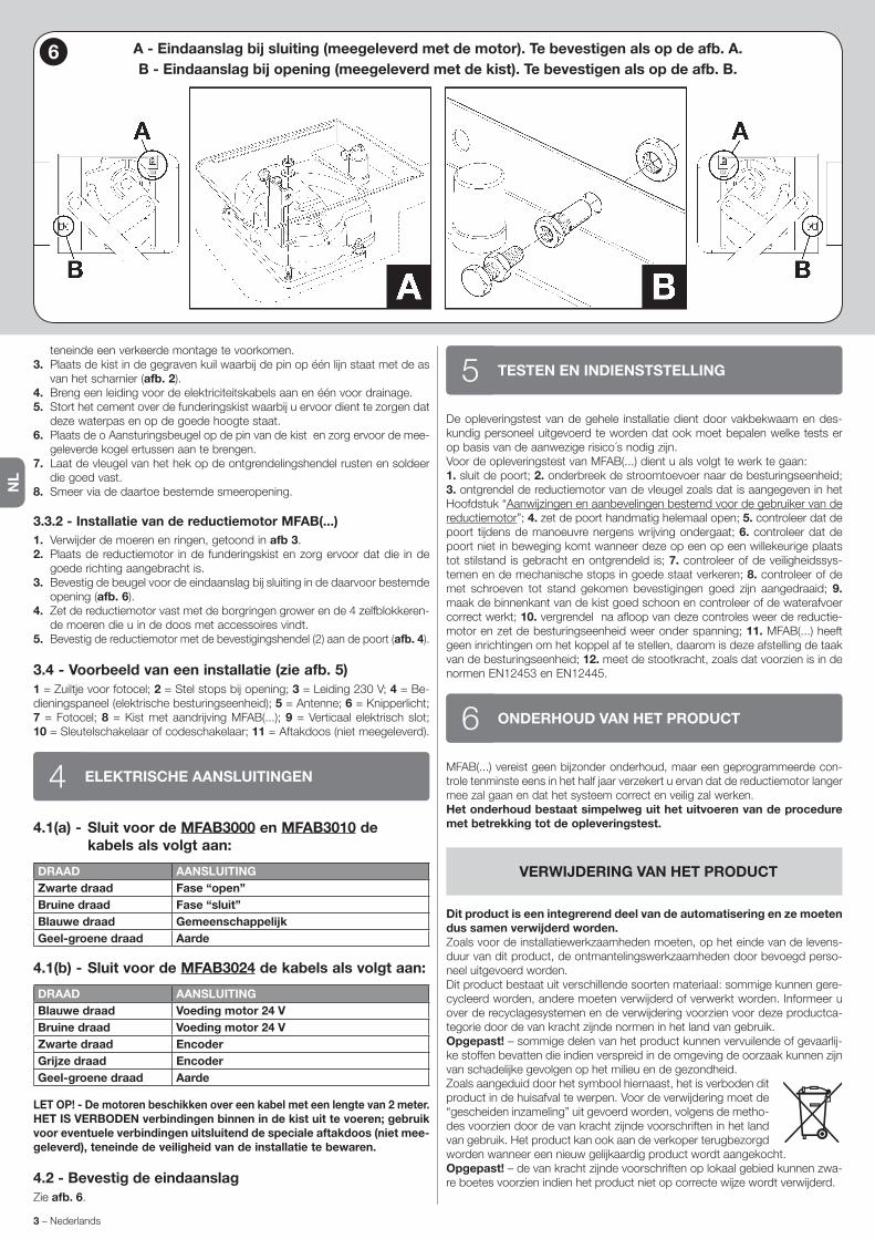
NL
3 – Nederlands
teneinde een verkeerde montage te voorkomen.3. Plaats de kist in de gegraven kuil waarbij de pin op één lijn staat met de as
van het scharnier (afb. 2).4. Breng een leiding voor de elektriciteitskabels aan en één voor drainage.5. Stort het cement over de funderingskist waarbij u ervoor dient te zorgen dat
deze waterpas en op de goede hoogte staat.6. Plaats de o Aansturingsbeugel op de pin van de kist en zorg ervoor de mee-
geleverde kogel ertussen aan te brengen.7. Laat de vleugel van het hek op de ontgrendelingshendel rusten en soldeer
die goed vast.8. Smeer via de daartoe bestemde smeeropening.
3.3.2 - Installatie van de reductiemotor MFAB(...)1. Verwijder de moeren en ringen, getoond in afb 3.2. Plaats de reductiemotor in de funderingskist en zorg ervoor dat die in de
goede richting aangebracht is.3. Bevestig de beugel voor de eindaanslag bij sluiting in de daarvoor bestemde
opening (afb. 6).4. Zet de reductiemotor vast met de borgringen grower en de 4 zelfblokkeren-
de moeren die u in de doos met accessoires vindt.5. Bevestig de reductiemotor met de bevestigingshendel (2) aan de poort (afb. 4).
3.4 - Voorbeeld van een installatie (zie afb. 5)1 = Zuiltje voor fotocel; 2 = Stel stops bij opening; 3 = Leiding 230 V; 4 = Be-dieningspaneel (elektrische besturingseenheid); 5 = Antenne; 6 = Knipperlicht; 7 = Fotocel; 8 = Kist met aandrijving MFAB(...); 9 = Verticaal elektrisch slot; 10 = Sleutelschakelaar of codeschakelaar; 11 = Aftakdoos (niet meegeleverd).
ELEKTRISCHE AANSLUITINGEN44.1(a) - Sluit voor de MFAB3000 en MFAB3010 de
kabels als volgt aan:
DRAAD AANSLUITINGZwarte draad Fase “open”Bruine draad Fase “sluit”Blauwe draad GemeenschappelijkGeel-groene draad Aarde
4.1(b) - Sluit voor de MFAB3024 de kabels als volgt aan:
DRAAD AANSLUITINGBlauwe draad Voeding motor 24 VBruine draad Voeding motor 24 VZwarte draad EncoderGrijze draad EncoderGeel-groene draad Aarde
LET OP! - De motoren beschikken over een kabel met een lengte van 2 meter.HET IS VERBODEN verbindingen binnen in de kist uit te voeren; gebruik voor eventuele verbindingen uitsluitend de speciale aftakdoos (niet mee-geleverd), teneinde de veiligheid van de installatie te bewaren.
4.2 - Bevestig de eindaanslagZie afb. 6.
TESTEN EN INDIENSTSTELLING5De opleveringstest van de gehele installatie dient door vakbekwaam en des-kundig personeel uitgevoerd te worden dat ook moet bepalen welke tests er op basis van de aanwezige risico´s nodig zijn.Voor de opleveringstest van MFAB(...) dient u als volgt te werk te gaan:1. sluit de poort; 2. onderbreek de stroomtoevoer naar de besturingseenheid; 3. ontgrendel de reductiemotor van de vleugel zoals dat is aangegeven in het Hoofdstuk “Aanwijzingen en aanbevelingen bestemd voor de gebruiker van de reductiemotor”; 4. zet de poort handmatig helemaal open; 5. controleer dat de poort tijdens de manoeuvre nergens wrijving ondergaat; 6. controleer dat de poort niet in beweging komt wanneer deze op een op een willekeurige plaats tot stilstand is gebracht en ontgrendeld is; 7. controleer of de veiligheidssys-temen en de mechanische stops in goede staat verkeren; 8. controleer of de met schroeven tot stand gekomen bevestigingen goed zijn aangedraaid; 9. maak de binnenkant van de kist goed schoon en controleer of de waterafvoer correct werkt; 10. vergrendel na afloop van deze controles weer de reductie-motor en zet de besturingseenheid weer onder spanning; 11. MFAB(...) heeft geen inrichtingen om het koppel af te stellen, daarom is deze afstelling de taak van de besturingseenheid; 12. meet de stootkracht, zoals dat voorzien is in de normen EN12453 en EN12445.
ONDERHOUD VAN HET PRODUCT6MFAB(...) vereist geen bijzonder onderhoud, maar een geprogrammeerde con-trole tenminste eens in het half jaar verzekert u ervan dat de reductiemotor langer mee zal gaan en dat het systeem correct en veilig zal werken.Het onderhoud bestaat simpelweg uit het uitvoeren van de procedure met betrekking tot de opleveringstest.
VERWIJDERING VAN HET PRODUCT
Dit product is een integrerend deel van de automatisering en ze moeten dus samen verwijderd worden.Zoals voor de installatiewerkzaamheden moeten, op het einde van de levens-duur van dit product, de ontmantelingswerkzaamheden door bevoegd perso-neel uitgevoerd worden.Dit product bestaat uit verschillende soorten materiaal: sommige kunnen gere-cycleerd worden, andere moeten verwijderd of verwerkt worden. Informeer u over de recyclagesystemen en de verwijdering voorzien voor deze productca-tegorie door de van kracht zijnde normen in het land van gebruik.Opgepast! – sommige delen van het product kunnen vervuilende of gevaarlij-ke stoffen bevatten die indien verspreid in de omgeving de oorzaak kunnen zijn van schadelijke gevolgen op het milieu en de gezondheid.Zoals aangeduid door het symbool hiernaast, het is verboden dit product in de huisafval te werpen. Voor de verwijdering moet de “gescheiden inzameling” uit gevoerd worden, volgens de metho-des voorzien door de van kracht zijnde voorschriften in het land van gebruik. Het product kan ook aan de verkoper terugbezorgd worden wanneer een nieuw gelijkaardig product wordt aangekocht.Opgepast! – de van kracht zijnde voorschriften op lokaal gebied kunnen zwa-re boetes voorzien indien het product niet op correcte wijze wordt verwijderd.
6 A - Eindaanslag bij sluiting (meegeleverd met de motor). Te bevestigen als op de afb. A.B - Eindaanslag bij opening (meegeleverd met de kist). Te bevestigen als op de afb. B.

NL
Nederlands – 4
AANWIJZINGEN: • Alle vermelde technische eigenschappen hebben betrekking op het product bij een omgevingstemperatuur van 20°C (± 5°C). • De firma Nice S.p.a. behoudt zich het recht voor, op om het even welk ogenblik dat zij het nodig acht, wijzigingen aan te brengen, terwijl dezelfde functionaliteit en gebruiksbestemming wordt behouden.
MFAB3000 MFAB3010 MFAB3000L MFAB3000/110 MFAB3024 MFAB3024HSStroomvoorziening 230 Vac; 50 Hz 230 Vac; 50 Hz 230 Vac; 50 Hz 110 Vac; 60 Hz 24 Vdc 24 VdcOpgenomen stroom 1.2 A 1.2 A 1.3 A 2.4 A 5 A 6 AOpgenomen vermogen 250 W 250 W 300 W 250 W 120 W 170 WIngebouwde condensator 10 uF 10 uF 10 uF 30 uF ––– –––Beschermingsklasse IP 67 IP 67 IP 67 IP 67 IP 67 IP 67Snelheid 1.14 Rpm 1.14 Rpm 0.8 Rpm 1.4 Rpm 1.4 Rpm 2.6 RpmKoppel 300 Nm 300 Nm 250 Nm 300 Nm 250 Nm 180 NmBedrijfstemperatuur van -20 °C tot +50 °COververhittingsbeveiliging 140 °C 140 °C 140 °C 140 °C ––– –––Werkingscyclus 30 % 40 % 30 % 30 % 80 % 80 %Gewicht 11 kg 11.5 kg 11 kg 11 kg 11 kg 11 kg
TECHNISCHE EIGENSCHAPPEN VAN HET PRODUCT
Op bestelling leverbare accessoires
PLA10 Verticaal 12 Vca-elektrisch slot PLA11 Horizontaal 12 Vca-elektrisch slot MEA3 Ontgrendeling met speciale hendel
MEA1 Inrichting voor opening op 360° MEA2 Ontgrendeling met slot
CE-verklaring van overeenstemming en in-bouwverklaring betreffende niet voltooide machinesVerklaring conform Richtlijnen: 2014/30/UE (EMC); 2006/42/CE (MD) bijlage II, deel B.
Opmerking - De inhoud van deze verklaring komt overeen met hetgeen is vastge-legd in het officiële document dat is gedeponeerd ten kantore van Nice S.p.a., en in het bijzonder met de laatste herziene en beschikbare versie ervan, vóór het drukken van deze handleiding. De hier gepresenteerde tekst is herzien om redactionele rede-nen. Een copie van de oorspronkelijke verklaring kan worden aangevraagd bij Nice S.p.a. (TV) Italië.
Nummer verklaring: 134/MFAB Revisie: 14 Taal: NL
Naam fabrikant: NICE s.p.a.Adres: Via Pezza Alta N°13, 31046 Rustignè di Oderzo (TV), ItaliëPersoon gemachtigd tot het samenstellen van het technisch dossier: NICE s.p.a. – Via Pezza Alta N°13, 31046 Rustignè di Oderzo (TV), ItaliëType product: Elektromechanische reductiemotor voor draaipoorten.Model / Type: MFAB3024, MFAB3000, MFAB3000L, MFAB3000/110, MFAB3010, MFAB3024HSAccessoires: Geen uitrustingen.
Ondergetekende Roberto Griffa, verklaart onder eigen verantwoordelijkheid als Chief Executive Officer dat deproducten voldoen aan de vereisten van de hierop volgende richtlijnen:• RICHTLIJN 2014/30/UE VAN HET EUROPEES PARLEMENT EN DE RAAD VAN DE
EUROPESE UNIE van 15 december 2004 betreffende de onderlinge aanpassing van de wetgevingen van de lidstaten inzake electromagnetische compatibiliteit en tot wijziging van richtlijn 89/336/EEG, volgens de hieropvolgende geharmoniseerde normen: EN 61000-6-2:2005; EN 61000-6-3:2007 + A1:2011.
Bovendien voldoet het product aan de hieropvolgende richtlijn volgens de voor “pseu-
do machines” geldende vereisten:• Richtlijn 2006/42/EG VAN HET EUROPEES PARLEMENT EN DE RAAD VAN DE
EUROPESE UNIE van 17 mei 2006 betreffende machines en tot wijziging van Richt-lijn 95/16/EG (herschikking)
– Hierbij verklaart men dat het relevante techinische dossier is ingevuld volgens de aanwijzingen in bijlage VII B van de richtlijn 2006/42/EG en dat daarbij aan de hier-opvolgende verplichte eisen is voldaan:
1.1.1 - 1.1.2 - 1.1.3 - 1.2.1 -1.2.6 - 1.5.1 -1.5.2 - 1.5.5 - 1.5.6 - 1.5.7 - 1.5.8 - 1.5.10 - 1.5.11.
– De fabrikant zal zorgdragen voor de overdracht van informatie bertreffende de niet voltooide machine, op speciaal verzoek van de wetgevende instanties zonder daar-bij schade te doen toekomen aan zijn eigen intellectueel eigendomsrecht.
– Mocht de onvoltooide machine in gebruik worden genomen in een land waar een andere taal wordt gesproken dan in deze verklaring is gebruikt, is de importeur ver-plicht de vertaling van het desbetreffende document aan de documentatie toe te voegen.
– Het is niet toegestaan de niet voltooide machine in gebruik te nemen voordat de uit-eindelijke machine waarop deze zal worden ingebouwd, en indien van toepassing geschikt is verklaard volgens de richtlijn 2006/42/EG.
Bovendien voldoet het product aan de hierop volgende normen: EN 60335-1:2002 + A1:2004 + A11:2004 + A12:2006 + A2:2006 + A13:2008 + A14:2010 + A15:2011; EN 60335-2-103:2003 + A11:2009.
Het product voldoet, waar van toepassing, aan de hierop volgende normen: EN 13241-1:2003 + A1:2011; EN 12445:2002; EN 12453:2002; EN 12978:2003 + A1:2009.
Oderzo, 21 april 2016Ing. Roberto Griffa
(Chief Executive Officer)


EN - OPERATION MANUAL
IT - MANUALE D’USO
FR - GUIDE DE L’UTILISATEUR
ES - MANUAL DE USO
DE - GEBRAUCHSANLEITUNG
PL - INSTRUKCJA OBSŁUGI
NL - GEBRUIKSHANDLEIDING
I
EN
ITFR
ES
DE
PL
NL

II
EN
Even if your automated system satisfies regulatory safety levels, this does not eliminate “residue risks”, that is, the possibility of dangerous situations being generated, usually due to irresponsible or incorrect use. For this reason we would like to give you some suggestions on how to avoid these risks.
• Before using your automated system for the first time, ask your fitter to explain how residue risks can arise and spend a few minutes reading the instructions and warnings for the user handbook that the fitter will have given you. Keep this manual for future use and, if you should ever sell your automated system, hand it over to the new owner.
ATTENTION! – Your automation is a machine that follows your com-mand faithfully; irresponsible and improper use can make it become dangerous:
– Do not command movement of the automation if there are persons, animals or objects within its radius of action.
– When operating a biased-off switch, make sure that other persons are kept away.
– When operating the gate, keep an eye on the automated mechanism and keep all bystanders at a safe distance until the movement has been completed.
– It is prohibited to touch parts of the automation while the gate or the door is in movement!
– The photocells are not a safety device but just an auxiliary device regarding safety. They are constructed with very high reliability technology but can, in extreme situations, undergo malfunctioning or even break and, in certain cases, the breakdown may not be im-mediately evident. For this reason, when using the automation, it is necessary to pay attention to the following warnings:
- Transit is only allowed when the gate or door is completely open with the panels at a standstill
- IT IS PROHIBITED to transit while the gate or door is closing! - Periodically check the correct functioning of the photocells and
have the envisioned maintenance checks performed at least every 6 months.
• Children:– This product is not intended to be used by persons (including children)
whose physical, sensory or mental capacities are reduced, or who lack the necessary experience or skill.
– Children must not play with the appliance.– Do not allow children to play with the fixed control devices of the product.
Keep the remote controls away from children.– Cleaning and maintenance to be carried out by the user must not be carried
out by unsupervised children.
• Anomalies: if any anomalous behaviour is noticed, remove the electric pow-er input to the plant and manually release the gear motor (see respective instruction manual) to make the gate function manually. Do not perform any self-taught repairs but request the intervention of your local installer.
• Maintenance: regular maintenance is required to keep the level of safety constant and guarantee the maximum duration of the entire automation
(every 6 months). Any control, maintenance or repairs operation must only be performed by qualified staff.
– Before working on the system (maintenance, cleaning), always disconnect the product from the mains power supply.
– Do not operate the product if anyone is working nearby; disconnect its power supply before permitting such work to be done.
• Do not modify the plant and programming parameters and control unit regulation: your installer is responsible.
• The inspection, periodic maintenance and any repairs must be docu-mented by whoever is carrying out the job. The documents must be kept by the owner of the plant. The only interventions that the user can perform periodically are cleaning the lenses of the photocells (use a slightly damp soft cloth) and the removal of any leaves or stones that could block the automation. Important – Release the gear motor manually before proceed-ing in order to prevent the gate being activated accidentally (see respective instruction book).
• Disposal: at the end of the automation’s life span, make sure that it is dis-posed of by qualified staff and that the materials are re-cycled or disposed of in compliance with the Standards valid at a local level.
• Breakage or power cut: while waiting for the intervention of your installer or the return of the power input, if the plant does not have buffer batteries, the automation can be used all the same: the gear motor must be released manually (see the dedicated paragraph successively) and move the gate panel manually as desired.
RELEASE AND BLOCK THE GEAR MOTOR MANUALLY
The gear motor has a mechanical system that allows to open and close the gate manually.These manual operations must be performed if there is a power cut or function-ing anomalies.
Instructions and cautions for the user of the gear motor
MEA2 Type KEY-Operated Release MEA3 Type Lever-Operated Release
1 Pull down the lock cover.
12
1
2
2 Insert the key and r otate it 90° clockwise.
3 Move the gate manually.
WARNING! – To restore automatic operation, relock the gate with the key (rotate the key 90°, counterclockwise).
3

III
IT
Anche se l’automazione in vostro possesso soddisfa il livello di sicurezza ri-chiesto dalle normative, questo non esclude l’esistenza di un “rischio residuo”, cioè la possibilità che si possano generare situazioni di pericolo, solitamente dovute ad un utilizzo incosciente o addirittura errato. Per questo motivo desi-deriamo darvi alcuni consigli sui comportamenti da seguire per evitare ogni in-conveniente.
• Prima di usare per la prima volta l’automazione, fatevi spiegare dall’in-stallatore l’origine dei rischi residui, e dedicate qualche minuto alla lettura del manuale di istruzioni ed avvertenze per l’utilizzatore consegnatovi dall’installatore. Conservate il manuale per ogni dubbio futuro e consegnate-lo ad un eventuale nuovo proprietario dell’automazione.
ATTENZIONE! – La vostra automazione è un macchinario che esegue fedelmente i vostri comandi; un uso incosciente ed improprio può farlo diventare pericoloso:
– Non comandate il movimento dell’automazione se nel suo raggio di azione si trovano persone, animali o cose.
– Tenere le persone lontane dalla porta quando questa viene movimen-tata mediante gli elementi di comando.
– Durante l’esecuzione della manovra controllare l’automazione e man-tenere le persone lontano da essa, fino al termine del movimento.
– È assolutamente vietato toccare parti dell’automazione mentre il cancello o il portone è in movimento!
– Le fotocellule non sono un dispositivo di sicurezza ma soltanto un di-spositivo ausiliario alla sicurezza. Sono costruite con tecnologia ad altissima affidabilità ma possono, in situazioni estreme, subire malfun-zionamenti o addirittura guastarsi e, in certi casi, il guasto potrebbe non essere subito evidente. Per questi motivi, durante l’utilizzo dell’au-tomazione è necessario fare attenzione alle seguenti avvertenze:
- Il transito è consentito solo se il cancello o portone è completa-mente aperto e con le ante ferme.
- È ASSOLUTAMENTE VIETATO transitare mentre il cancello o il por-tone si sta chiudendo!
- Verificare periodicamente il corretto funzionamento delle fotocel-lule e far eseguire i controlli di manutenzione previsti, almeno ogni 6 mesi.
• Bambini:– Il prodotto non è destinato a essere usato da persone (bambini compresi) le
cui capacità fisiche, sensoriali o mentali siano ridotte, oppure con mancanza di esperienza o di conoscenza.
– I bambini non devono giocare con l’apparecchio.– Non permettere ai bambini di giocare con i dispositivi di comando del prodot-
to. Tenere i telecomandi lontano dai bambini.– La pulizia e la manutenzione destinata ad essere effettuata dall’utilizzatore
non deve essere effettuata da bambini senza sorveglianza.
• Anomalie: se viene notato un qualunque comportamento anomalo dell’au-tomazione, togliere l’alimentazione elettrica all’impianto ed eseguire lo sbloc-co manuale del motoriduttore (vedere rispettivo manuale istruzioni) per far funzionare manualmente il cancello. Non effettuare alcuna riparazione da autodidatta ma richiedere l’intervento del vostro installatore di fiducia.
• Manutenzione: per mantenere costante il livello di sicurezza e per garantire la massima durata dell’intera automazione è necessaria una manutenzione regolare (ogni 6 mesi). Qualunque intervento di controllo, manutenzio-ne o riparazione deve essere eseguito solo da personale qualificato.
– Prima degli interventi sull’impianto (manutenzione, pulizia), disconnettere sem-pre il prodotto dalla rete di alimentazione.
– Non comandare il prodotto se nelle sue vicinanze ci sono persone che svol-gono lavori sull’automazione; scollegate l’alimentazione elettrica prima di far eseguire questi lavori.
• Non modificare l’impianto e i parametri di programmazione e di re-golazione della centrale di comando: la responsabilità è del vostro installatore.
• Il collaudo, le manutenzioni periodiche e le eventuali riparazioni de-vono essere documentate da chi esegue il lavoro. I documenti devo-no essere conservati dal proprietario dell’impianto. Gli unici interventi che l’utilizzatore può eseguire periodicamente, sono la pulizia dei vetrini delle fotocellule (utilizzare un panno morbido e leggermente umido) e la rimozio-ne di eventuali foglie o sassi che potrebbero ostacolare l’automatismo. Im-portante – Prima di procedere, per impedire che qualcuno possa azionare innavertitamente il cancello, sbloccare manualmente il motoriduttore (vedere rispettivo manuale istruzioni).
• Smaltimento: al termine della vita dell’automazione, assicuratevi che lo smantellamento sia eseguito da personale qualificato e che i materiali venga-no riciclati o smaltiti secondo le norme valide a livello locale.
• Rottura o assenza di alimentazione: in attesa dell’intervento del vostro installatore o del ritorno dell’energia elettrica, se l’impianto non è dotato di batterie tampone, l’automazione può essere ugualmente utilizzata: occorre eseguire lo sblocco manuale del motoriduttore (vedere di seguito il paragrafo dedicato) e muovere l’anta del cancello manualmente come si desidera.
SBLOCCARE E BLOCCARE IL MOTORIDUTTORE MA-NUALMENTE
Il motoriduttore è dotato di un sistema meccanico che consente di aprire e chiudere il cancello manualmente.Queste operazioni manuali devono essere eseguite nei casi di mancanza di corrente elettrica o di anomalie di funzionamento.
Istruzioni ed avvertenze destinate all’utilizzatore del motoriduttore
Sblocco a CHIAVE tipo MEA2 Sblocco a leva tipo MEA3
1 Abbassare il coperchio copriserratura.
12
1
2
2 Inserire la chiave e ruotarla in senso orario di 90°.
3 Agire manualmente sulI’anta.
ATTENZIONE! – Per ripri-stinare il funzionamen-to automatico, ribloccare il cancello con la chiave (ruotare la chiave di 90°, in senso antiorario). 3
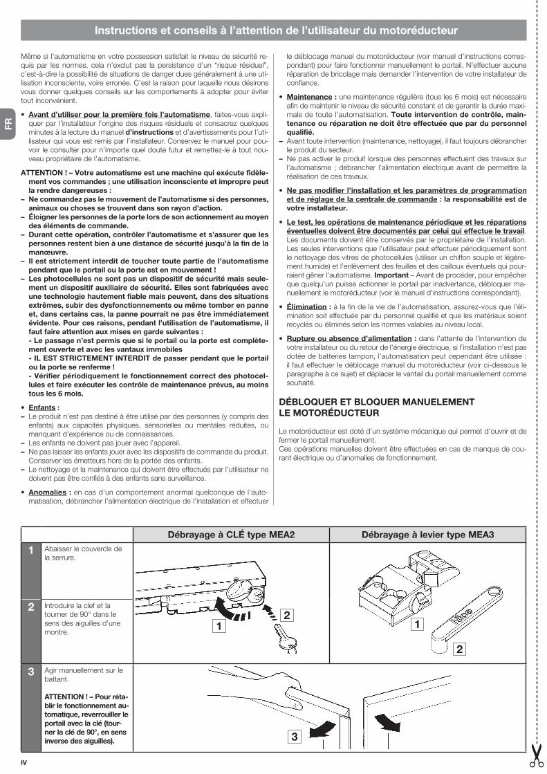
IV
FR
Instructions et conseils à l’attention de l’utilisateur du motoréducteur
Même si l’automatisme en votre possession satisfait le niveau de sécurité re-quis par les normes, cela n’exclut pas la persistance d’un “risque résiduel”, c’est-à-dire la possibilité de situations de danger dues généralement à une uti-lisation inconsciente, voire erronée. C’est la raison pour laquelle nous désirons vous donner quelques conseils sur les comportements à adopter pour éviter tout inconvénient.
• Avant d’utiliser pour la première fois l’automatisme, faites-vous expli-quer par l’installateur l’origine des risques résiduels et consacrez quelques minutes à la lecture du manuel d’instructions et d’avertissements pour l’uti-lisateur qui vous est remis par l’installateur. Conservez le manuel pour pou-voir le consulter pour n’importe quel doute futur et remettez-le à tout nou-veau propriétaire de l’automatisme.
ATTENTION ! – Votre automatisme est une machine qui exécute fidèle-ment vos commandes ; une utilisation inconsciente et impropre peut la rendre dangereuses :
– Ne commandez pas le mouvement de l’automatisme si des personnes, animaux ou choses se trouvent dans son rayon d’action.
– Éloigner les personnes de la porte lors de son actionnement au moyen des éléments de commande.
– Durant cette opération, contrôler l’automatisme et s’assurer que les personnes restent bien à une distance de sécurité jusqu’à la fin de la manœuvre.
– Il est strictement interdit de toucher toute partie de l’automatisme pendant que le portail ou la porte est en mouvement !
– Les photocellules ne sont pas un dispositif de sécurité mais seule-ment un dispositif auxiliaire de sécurité. Elles sont fabriquées avec une technologie hautement fiable mais peuvent, dans des situations extrêmes, subir des dysfonctionnements ou même tomber en panne et, dans certains cas, la panne pourrait ne pas être immédiatement évidente. Pour ces raisons, pendant l’utilisation de l’automatisme, il faut faire attention aux mises en garde suivantes :
- Le passage n’est permis que si le portail ou la porte est complète-ment ouverte et avec les vantaux immobiles
- IL EST STRICTEMENT INTERDIT de passer pendant que le portail ou la porte se renferme !
- Vérifier périodiquement le fonctionnement correct des photocel-lules et faire exécuter les contrôle de maintenance prévus, au moins tous les 6 mois.
• Enfants :– Le produit n’est pas destiné à être utilisé par des personnes (y compris des
enfants) aux capacités physiques, sensorielles ou mentales réduites, ou manquant d’expérience ou de connaissances.
– Les enfants ne doivent pas jouer avec l’appareil.– Ne pas laisser les enfants jouer avec les dispositifs de commande du produit.
Conserver les émetteurs hors de la portée des enfants.– Le nettoyage et la maintenance qui doivent être effectués par l’utilisateur ne
doivent pas être confiés à des enfants sans surveillance.
• Anomalies : en cas d’un comportement anormal quelconque de l’auto-matisation, débrancher l’alimentation électrique de l’installation et effectuer
le déblocage manuel du motoréducteur (voir manuel d’instructions corres-pondant) pour faire fonctionner manuellement le portail. N’effectuer aucune réparation de bricolage mais demander l’intervention de votre installateur de confiance.
• Maintenance : une maintenance régulière (tous les 6 mois) est nécessaire afin de maintenir le niveau de sécurité constant et de garantir la durée maxi-male de toute l’automatisation. Toute intervention de contrôle, main-tenance ou réparation ne doit être effectuée que par du personnel qualifié.
– Avant toute intervention (maintenance, nettoyage), il faut toujours débrancher le produit du secteur.
– Ne pas activer le produit lorsque des personnes effectuent des travaux sur l’automatisme ;débrancher l’alimentationélectriqueavantdepermettre laréalisation de ces travaux.
• Ne pas modifier l’installation et les paramètres de programmation et de réglage de la centrale de commande : la responsabilité est de votre installateur.
• Le test, les opérations de maintenance périodique et les réparations éventuelles doivent être documentés par celui qui effectue le travail. Les documents doivent être conservés par le propriétaire de l’installation. Les seules interventions que l’utilisateur peut effectuer périodiquement sont le nettoyage des vitres de photocellules (utiliser un chiffon souple et légère-ment humide) et l’enlèvement des feuilles et des cailloux éventuels qui pour-raient gêner l’automatisme. Important – Avant de procéder, pour empêcher que quelqu’un puisse actionner le portail par inadvertance, débloquer ma-nuellement le motoréducteur (voir le manuel d’instructions correspondant).
• Élimination : à la fin de la vie de l’automatisation, assurez-vous que l’éli-mination soit effectuée par du personnel qualifié et que les matériaux soient recyclés ou éliminés selon les normes valables au niveau local.
• Rupture ou absence d’alimentation : dans l’attente de l’intervention de votre installateur ou du retour de l’énergie électrique, si l’installation n’est pas dotée de batteries tampon, l’automatisation peut cependant être utilisée : il faut effectuer le déblocage manuel du motoréducteur (voir ci-dessous le paragraphe à ce sujet) et déplacer le vantail du portail manuellement comme souhaité.
DÉBLOQUER ET BLOQUER MANUELEMENT LE MOTORÉDUCTEUR
Le motoréducteur est doté d’un système mécanique qui permet d’ouvrir et de fermer le portail manuellement.Ces opérations manuelles doivent être effectuées en cas de manque de cou-rant électrique ou d’anomalies de fonctionnement.
Débrayage à CLÉ type MEA2 Débrayage à levier type MEA3
1 Abaisser le couvercle de la serrure.
12
1
2
2 Introduire la clef et la tourner de 90° dans le sens des aiguilles d’une montre.
3 Agir manuellement sur le battant.
ATTENTION ! – Pour réta-blir le fonctionnement au-tomatique, reverrouiller le portail avec la clé (tour-ner la clé de 90°, en sens inverse des aiguilles). 3

V
ES
Instrucciones y advertencias destinadas al utilizador del motorreductor
Aunque bien su automatización satisfaga el nivel de seguridad requerido por las normativas, esto no excluye la existencia de un “riesgo residual”, es decir, la posibilidad de que se puedan crear situaciones de peligro causadas por un uso inconsciente o incorrecto. Por dicho motivo, a continuación le damos algunos consejos sobre cómo comportarse para evitar inconvenientes.
• Antes de usar por primera vez la automatización, pida a su instalador que le explique el origen de los riesgos residuales y lea este manual de ins-trucciones y advertencias para el usuario entregado por el instalador. Conserve el manual por cualquier problema que pueda surgir y recuerde en-tregarlo a un posible nuevo dueño de la automatización.
¡ATENCIÓN! – Su automatismo es una máquina que lleva a cabo fiel-mente los mandos que se le dan, por tanto, un uso inconsciente e in-adecuado lo puede volver peligroso:
– No ordene el movimiento del automatismo si en su rayo de acción se encuentran personas, animales o cosas.
– Mantener a las personas alejadas al accionar el movimiento de la puerta mediante los elementos de mando.
– Durante la ejecución de una maniobra, controlar la automatización y asegurarse de que las personas se mantengan alejadas hasta que termine el movimiento.
– ¡Se prohíbe absolutamente tocar las partes del automatismo mien-tras la cancela o el portal están en movimiento!
– Las fotocélulas no son un dispositivo de seguridad, sino solo un dis-positivo auxiliar para la misma. Están fabricadas con tecnología de altísima fiabilidad, pero en situación extremas, podrían sufrir proble-mas de funcionamiento o incluso averiarse, y en algunos casos la avería podría no encontrarse al instante. Por esta razón durante el uso del automatismo es necesario prestar atención a las siguientes advertencias:
- Se permite el tránsito solo si la cancela o portal están completa-mente abiertos o con las hojas detenidas
- ¡SE PROHÍBE ABSOLUTAMENTE transitar mientras la cancela o el portón se están cerrando!
- Controle periódicamente el funcionamiento correcto de las foto-células y haga realizar los controles de mantenimiento previstos, al menos cada 6 meses.
• Niños:– El producto no puede ser utilizado por los niños ni por personas con disca-
pacidades físicas, sensoriales o mentales, o bien carentes de experiencia o conocimiento.
– Los niños no deben jugar con el aparato.– No permitir que los niños jueguen con los dispositivos de mando del produc-
to. Mantener los mandos a distancia fuera del alcance de los niños.– La limpieza y el mantenimiento del aparato deben ser efectuados por el
usuario y no por niños sin vigilancia.
• Anomalías: si se nota cualquier comportamiento anómalo del automatis-mo, quite la alimentación eléctrica de la instalación y bloquee manualmente el motorreductor (véase el respectivo manual de instrucciones), para hacer funcionar manualmente la cancela. No lleve a cabo reparaciones sin ayuda,
solicite la intervención de su instalador de confianza.
• Mantenimiento: para mantener constante el nivel de seguridad y para ga-rantizar la máxima duración del sistema completo de automatización es ne-cesario efectuar un mantenimiento regular (cada 6 meses). Cualquier inter-vención de control, mantenimiento o reparación la debe realizar solo personal calificado.
– Antes de realizar cualquier operación en la instalación (limpieza, manteni-miento) hay que desconectar el aparato de la red de alimentación.
– No poner en funcionamiento el producto cuando en sus proximidades se es-tén realizando tareas en la automatización; es necesario desconectar la fuen-te de alimentación antes de realizar estas tareas.
• No modifique la instalación y los parámetros de programación y de regulación de la central de mando: la responsabilidad es de su ins-talador.
• La inspección y pruebas, los mantenimientos periódicos y las posi-bles reparaciones las debe documentar quien los realiza. Los docu-mentos los debe conservar el propietario de la instalación. Las únicas inter-venciones que el usuario puede realizar periódicamente, son la limpieza de los cristales de las fotocélulas (utilice un paño suave y humedecido) y la eli-minación de posibles hojas o piedras que podrían obstaculizar el automa-tismo. Importante – Antes de continuar, para impedir que alguien pueda accionar inesperadamente la cancela, desbloquee manualmente el motorre-ductor (véase respectivo manual de instrucciones).
• Eliminación: al final de la vida útil del automatismo, asegúrese de que la de-molición la realice personal calificado y que los materiales se reciclen o elimi-nen según las normas válidas a nivel local.
• Rotura o ausencia de alimentación eléctrica: mientras se espera la in-tervención de su instalador o el regreso de la corriente eléctrica, si la insta-lación no tiene baterías tampón, el automatismo se puede utilizar igualmen-te: se debe desbloquear manualmente el motorreductor (véase a continua-ción la sección correspondiente) y mover la hoja de la cancela manualmente como se desea.
DESBLOQUEAR Y BLOQUEAR EL MOTORREDUCTOR MANUALMENTE
El motorreductor tiene un sistema mecánico que permite abrir y cerrar la can-cela manualmente.Estas operaciones manuales se deben realizar en los casos de falta de corrien-te eléctrica o de anomalías de funcionamiento.
Desbloqueo con LLAVE tipo MEA2 Desbloqueo con palanca tipo MEA3
1 Baje la tapa que cubre la cerradura.
12
1
2
2 Introduzca la llave y gírela 90° en el sentido horario.
3 Mueva manualmente la hoja.
¡ATENCIÓN! – Para resta-blecer el funcionamiento automático, rebloquear la cancela con la llave (girar la llave 90°, en el sentido antihorario). 3
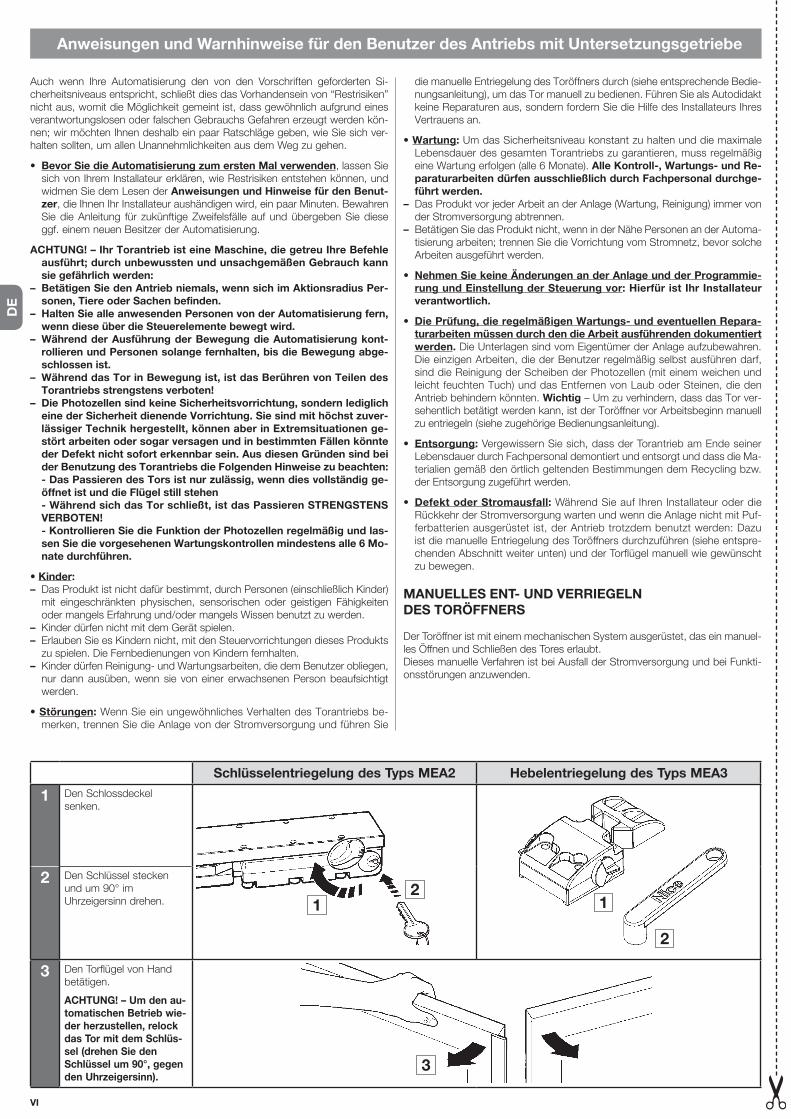
VI
DE
Anweisungen und Warnhinweise für den Benutzer des Antriebs mit Untersetzungsgetriebe
Auch wenn Ihre Automatisierung den von den Vorschriften geforderten Si-cherheitsniveaus entspricht, schließt dies das Vorhandensein von “Restrisiken” nicht aus, womit die Möglichkeit gemeint ist, dass gewöhnlich aufgrund eines verantwortungslosen oder falschen Gebrauchs Gefahren erzeugt werden kön-nen; wir möchten Ihnen deshalb ein paar Ratschläge geben, wie Sie sich ver-halten sollten, um allen Unannehmlichkeiten aus dem Weg zu gehen.
• Bevor Sie die Automatisierung zum ersten Mal verwenden, lassen Sie sich von Ihrem Installateur erklären, wie Restrisiken entstehen können, und widmen Sie dem Lesen der Anweisungen und Hinweise für den Benut-zer, die Ihnen Ihr Installateur aushändigen wird, ein paar Minuten. Bewahren Sie die Anleitung für zukünftige Zweifelsfälle auf und übergeben Sie diese ggf. einem neuen Besitzer der Automatisierung.
ACHTUNG! – Ihr Torantrieb ist eine Maschine, die getreu Ihre Befehle ausführt; durch unbewussten und unsachgemäßen Gebrauch kann sie gefährlich werden:
– Betätigen Sie den Antrieb niemals, wenn sich im Aktionsradius Per-sonen, Tiere oder Sachen befinden.
– Halten Sie alle anwesenden Personen von der Automatisierung fern, wenn diese über die Steuerelemente bewegt wird.
– Während der Ausführung der Bewegung die Automatisierung kont-rollieren und Personen solange fernhalten, bis die Bewegung abge-schlossen ist.
– Während das Tor in Bewegung ist, ist das Berühren von Teilen des Torantriebs strengstens verboten!
– Die Photozellen sind keine Sicherheitsvorrichtung, sondern lediglich eine der Sicherheit dienende Vorrichtung. Sie sind mit höchst zuver-lässiger Technik hergestellt, können aber in Extremsituationen ge-stört arbeiten oder sogar versagen und in bestimmten Fällen könnte der Defekt nicht sofort erkennbar sein. Aus diesen Gründen sind bei der Benutzung des Torantriebs die Folgenden Hinweise zu beachten:
- Das Passieren des Tors ist nur zulässig, wenn dies vollständig ge-öffnet ist und die Flügel still stehen
- Während sich das Tor schließt, ist das Passieren STRENGSTENS VERBOTEN!
- Kontrollieren Sie die Funktion der Photozellen regelmäßig und las-sen Sie die vorgesehenen Wartungskontrollen mindestens alle 6 Mo-nate durchführen.
• Kinder:– Das Produkt ist nicht dafür bestimmt, durch Personen (einschließlich Kinder)
mit eingeschränkten physischen, sensorischen oder geistigen Fähigkeiten oder mangels Erfahrung und/oder mangels Wissen benutzt zu werden.
– Kinder dürfen nicht mit dem Gerät spielen.– Erlauben Sie es Kindern nicht, mit den Steuervorrichtungen dieses Produkts
zu spielen. Die Fernbedienungen von Kindern fernhalten.– Kinder dürfen Reinigung- und Wartungsarbeiten, die dem Benutzer obliegen,
nur dann ausüben, wenn sie von einer erwachsenen Person beaufsichtigt werden.
• Störungen: Wenn Sie ein ungewöhnliches Verhalten des Torantriebs be-merken, trennen Sie die Anlage von der Stromversorgung und führen Sie
die manuelle Entriegelung des Toröffners durch (siehe entsprechende Bedie-nungsanleitung), um das Tor manuell zu bedienen. Führen Sie als Autodidakt keine Reparaturen aus, sondern fordern Sie die Hilfe des Installateurs Ihres Vertrauens an.
• Wartung: Um das Sicherheitsniveau konstant zu halten und die maximale Lebensdauer des gesamten Torantriebs zu garantieren, muss regelmäßig eine Wartung erfolgen (alle 6 Monate). Alle Kontroll-, Wartungs- und Re-paraturarbeiten dürfen ausschließlich durch Fachpersonal durchge-führt werden.
– Das Produkt vor jeder Arbeit an der Anlage (Wartung, Reinigung) immer von der Stromversorgung abtrennen.
– Betätigen Sie das Produkt nicht, wenn in der Nähe Personen an der Automa-tisierung arbeiten; trennen Sie die Vorrichtung vom Stromnetz, bevor solche Arbeiten ausgeführt werden.
• Nehmen Sie keine Änderungen an der Anlage und der Programmie-rung und Einstellung der Steuerung vor: Hierfür ist Ihr Installateur verantwortlich.
• Die Prüfung, die regelmäßigen Wartungs- und eventuellen Repara-turarbeiten müssen durch den die Arbeit ausführenden dokumentiert werden. Die Unterlagen sind vom Eigentümer der Anlage aufzubewahren. Die einzigen Arbeiten, die der Benutzer regelmäßig selbst ausführen darf, sind die Reinigung der Scheiben der Photozellen (mit einem weichen und leicht feuchten Tuch) und das Entfernen von Laub oder Steinen, die den Antrieb behindern könnten. Wichtig – Um zu verhindern, dass das Tor ver-sehentlich betätigt werden kann, ist der Toröffner vor Arbeitsbeginn manuell zu entriegeln (siehe zugehörige Bedienungsanleitung).
• Entsorgung: Vergewissern Sie sich, dass der Torantrieb am Ende seiner Lebensdauer durch Fachpersonal demontiert und entsorgt und dass die Ma-terialien gemäß den örtlich geltenden Bestimmungen dem Recycling bzw. der Entsorgung zugeführt werden.
• Defekt oder Stromausfall: Während Sie auf Ihren Installateur oder die Rückkehr der Stromversorgung warten und wenn die Anlage nicht mit Puf-ferbatterien ausgerüstet ist, der Antrieb trotzdem benutzt werden: Dazu ist die manuelle Entriegelung des Toröffners durchzuführen (siehe entspre-chenden Abschnitt weiter unten) und der Torflügel manuell wie gewünscht zu bewegen.
MANUELLES ENT- UND VERRIEGELNDES TORÖFFNERS
Der Toröffner ist mit einem mechanischen System ausgerüstet, das ein manuel-les Öffnen und Schließen des Tores erlaubt.Dieses manuelle Verfahren ist bei Ausfall der Stromversorgung und bei Funkti-onsstörungen anzuwenden.
Schlüsselentriegelung des Typs MEA2 Hebelentriegelung des Typs MEA3
1 Den Schlossdeckel senken.
12
1
2
2 Den Schlüssel stecken und um 90° im Uhrzeigersinn drehen.
3 Den Torflügel von Hand betätigen.
ACHTUNG! – Um den au-tomatischen Betrieb wie-der herzustellen, relock das Tor mit dem Schlüs-sel (drehen Sie den Schlüssel um 90°, gegen den Uhrzeigersinn).
3

VII
PL
Instrukcje i ostrzeżenia przeznaczone dla użytkownika motoreduktora
Gdyautomatykaspełniawaszewymaganiawzakresiebezpieczeństwaizgod-nieznormamiprawnyminieznaczyto,żenieistniejąinneniebezpieczeństwa.Mogąsiębowiemutworzyćsięsytuacjenibezpiecznespowodowanenieod-powiedzialnymibłędnymużytkowaniem.Dlategoteżchcemyprzekazaćwamużytecznewskazówkiwceluuniknięciatakichniekorzystnychsytuacji.
• Przed pierwszym uruchomieniem automatyki,należypoprosić instala-toraodokładneprzedstawienie ewentualnychniebezpieczeństw.Przeczy-taćinstrukcję i ostrzeżenia dla instalatora,którąwamprzekazał.Należyprzechowywaćinstrukcjewcelumożliwychpóźniejszychkonsultacjiiprze-kazaćjąewentualnemunastępnemuużytkownikowibramy.
UWAGA! – Wasz automat jest mechanizmem, który wiernie wykonuje Wasze polecenia; bezmyślne i niewłaściwe użycie może stać się nie-bezpieczne:
– Nie zlecać automatowi ruchu, jeśli w promieniu jego działania znaj-dują się osoby, zwierzęta lub rzeczy.
– Osoby trzecie nie powinny się znajdować w pobliżu bramy podczas jej przesuwania przy użyciu elementów sterowniczych.
– Podczas wykonywania manewru, należy nadzorować automatykę i zadbać o to, aby inne osoby nie zbliżały się do urządzenia, aż do cza-su zakończenia czynności.
– Surowo zakazane jest dotykanie części automatu, podczas gdy bramka lub brama są w ruchu!
– Fotokomórki nie są urządzeniem bezpieczeństwa, lecz jedynie urzą-dzeniem pomocniczym ze względów bezpieczeństwa. Zostały wy-konane z zastosowaniem najlepszej technologii, lecz w krańcowych sytuacjach, mogą ulec nieprawidłowościom, czy nawet uszkodzić się i w niektórych przypadkach, uszkodzenie to mogłoby nie być od razu widoczne. Z tego względu, podczas używania automatu, należy zwracać uwagę na następujące ostrzeżenia:
- Przejście/przejazd są możliwe wyłącznie, gdy bramka lub brama są całkowicie otwarte, a skrzydła nieruchome
- SUROWO ZABRANIA SIĘ przechodzić/przejeżdżać, gdy brama lub bramka zamyka się!
- Okresowo należy sprawdzać właściwe funkcjonowanie fotokomó-rek i zlecić wykonanie zaplanowanych kontroli konserwacyjnych przynajmniej co 6 miesięcy.
• Dzieci:– Urządzenieniejestprzeznaczonedoużytkuprzezosoby(równieżdzieci),któ-rychmożliwościfizyczne,czuciowelubumysłowesąograniczone.Zurządze-nianiemogąrównieżkorzystaćosobybezdoświadczeniaistosownejwiedzy.
– Niezezwalaćdzieciomnazabawęurządzeniem.– Niezezwalaćdzieciomnazabawęurządzeniamisterującymiproduktu.Prze-chowywaćpilotywmiejscuniedostępnymdladzieci.
– Czyszczenieikonserwacja,zaktórąjestodpowiedzialnyużytkownik,niepo-winnabyćwykonywanaprzezdziecipozbawioneopieki.
• Nieprawidłowości: jeślizauważysięjakiekolwieknieprawidłowezacho-wanieautomatu,należyodłączyćzasilanieelektryczneodinstalacjiiręcznieodblokowaćsiłownik(patrzodpowiedniainstrukcjaobsługi),abyręczniedo-prowadzićdopracybramki.Niewykonywaćsamodzielnieżadnychnapraw,
leczzwrócićsięointerwencjędoWaszegozaufanegoinstalatora.
• Konserwacja:abyzachowaćpoziombezpieczeństwaizagwarantowaćmaksymalnyokresfunkcjonowaniacałegoautomatu,konserwacjęnależyprzeprowadzaćregularnie(co6miesięcy).Jakiejkolwiek interwencji do-tyczącej kontroli, konserwacji czy naprawy może dokonać wyłącznie wykwalifikowany personel.
– Przedwykonaniemdziałańna instalacji (konserwacja,czyszczenie),należyzawszeodłączyćproduktodsiecizasilającej.
– Niesterowaćautomatyką,jeżeliwjejpobliżuznajdująsięosobywykonująceczynności;przedwykonaniemtychczynnościnależyodłączyćzasilanieelek-tryczne.
• Nie wprowadzać zmian do instalacji i parametrów programowania i regulacji centrali: jest to zadanie dla Waszego instalatora.
• Osoba przeprowadzająca test kontrolny, konserwację okresową i do-konująca ewentualnych napraw, musi to udokumentować. Takie doku-mentymusiprzechowaćwłaścicielinstalacji.Jedyneczynności,któremożewykonaćużytkownikodczasudoczasu,toczyszczenieszybekfotokomórek(korzystajączmiękkiej,lekkowilgotnejszmatki)iusunięcieewentualnychliściczykamyków,mogącychzablokowaćautomat.Ważne – Przed kontynu-acją,należyręcznieodblokowaćsiłownik,abyniedopuścić,żebyktośnie-oczekiwanieuruchomiłbramkę(patrzodpowiedniainstrukcjaobsługi).
• Utylizacja:nazakończenieokresufunkcjonowaniaautomatu,należyupew-nićsię,żeutylizacjidokonawykwalifikowanypersonel,amateriałyzostanąpoddane recyklingowi lub utylizacji zgodnie z miejscowymi przepisami.
• Uszkodzenie lub brak zasilania: czekającnainterwencjęWaszegoin-stalatoralubnapowrótdopływuenergiielektrycznej,jeśliinstalacjaniejestwyposażonawbateriebuforowe,zautomatumożnakorzystaćwdalszymciągu:należyręcznieodblokowaćsiłownik(patrzponiżejspecjalnyparagraf)iręcznieporuszyćskrzydłembramkitak,jaksiętegowymaga.
ODBLOKOWAĆ I ZABLOKOWAĆ SIŁOWNIK RĘCZNIE
Siłownikwyposażonyjestwmechanicznysystem,umożliwiającyotwarcieiza-mknięciebramkiręcznie.Czynnościtenależywykonaćręczniewrazieprzerwywdopływieprąduelek-trycznegolubnieprawidłowości.
Odblokada na KLUCZ typu MEA2 Odblokada z dzwignią typu MEA3
1 Opuśćpokrywęobejmującyzamek.
12
1
2
2 Włożyćklucziprzekręcićo 90 w kierunku ruchu wskazówek zegara.
3 Ręcznieotworzyćskrzydło.
UWAGA! – Aby przy-wrócić automatyczne działanie, ponownie za-blokować bramę z klu-czem (przekręcić klu-czyk o 90°, w lewo). 3

VIII
NL
Instructies en aanwijzingen bestemd voor de gebruiker van de reductiemotor
Ook al beantwoordt de automatisering in uw bezit aan het in normen en wet-ten voorgeschreven veiligheidsniveau, dit sluit niet uit dat er een “restrisico” be-staat, dat wil zeggen de mogelijkheid dat er gevaarlijke situaties kunnen ont-staan, die gewoonlijk te wijten zijn aan onverantwoordelijk of zelfs verkeerd ge-bruik. Hierom willen wij u enige adviezen geven hoe u met de automatisering dient om te gaan teneinde elk eventueel probleem te voorkomen.
• Voordat u de automatisering voor de eerste maal gaat gebruiken, is het raadzaam u door de installateur te laten uitleggen waar de restrisico’s ontstaan, en enkele minuten van uw tijd te besteden aan het lezen van deze handleiding met aanwijzingen en aanbevelingen voor de gebruiker die de installateur u overhandigd heeft. Bewaar deze handleiding voor eventuele toekomstige twijfels en geef haar aan een eventuele nieuwe eigenaar van de automatisering.
LET OP! - Uw automatisering is een machine die uw opdrachten trouw uitvoert. Onnadenkend en oneigenlijk gebruik kunnen het automatis-me gevaarlijk maken:
– Laat het automatisme geen bewegingen uitvoeren indien mensen, dieren of voorwerpen zich in diens actieradius bevinden.
– Houd personen uit de buurt van de poort wanneer deze wordt bewo-gen met behulp van de bedieningselementen.
– Controleer de automatisering tijdens het uitvoeren van de manoeuv-re en houd personen op enige afstand tot de beweging voltooid is.
– Het is absoluut verboden om de delen van de automatisering aan te raken terwijl het hek of de poort in beweging is!
– De fotocellen zijn geen veiligheidsvoorziening maar alleen een hulp-voorziening voor de veiligheid. Deze zijn geconstrueerd met een zeer betrouwbaar technologie maar kunnen in extreme situaties storin-gen ondergaan of zelfs kapot gaan en in zekere gevallen zou het de-fect niet onmiddellijk duidelijk zijn. Om deze redenen is het tijdens het gebruik van de automatisering nodig om op de volgende waar-schuwingen te letten:
- Doorgang is alleen toegestaan wanneer het hek of de poort volledig geopend is en de hekvleugels stilstaan
- De doorgang is ABSOLUUT VERBODEN terwijl het hek of de poort aan het sluiten is!
- Controleer regelmatig de correcte werking van de fotocellen en laat minstens om de 6 maanden de voorziene onderhoudscontroles uit-voeren.
• Kinderen:– Het product is niet bestemd voor gebruik door personen (inclusief kinderen)
met lichamelijke, zintuiglijke of geestelijke beperkingen of met gebrek aan ervaring of kennis.
– Kinderen mogen niet met het apparaat spelen.– Laat kinderen niet met de bedieningselementen van het product spelen.
Houd de afstandsbedieningen buiten het bereik van kinderen.– Reinigings- en onderhoudswerkzaamheden die door de gebruiker kunnen
worden uitgevoerd, mogen niet worden toevertrouwd aan kinderen die niet onder toezicht staan.
• Afwijkingen: indien afwijkend gedrag van het automatisme van welke aard
ook geconstateerd wordt, neem dan de elektrische voeding naar de instal-latie weg en verricht de manuele deblokkering van de reductiemotor (zie de respectievelijke handleiding met instructies) om het hek manueel te laten werken. Verricht zelf geen enkele reparatie maar vraag om de tussenkomst van uw vertrouwensinstallateur.
• Onderhoud: Om het veiligheidsniveau constant te houden en om de maxi-male levensduur van de volledige automatisering te garanderen, is het noodzakelijk om regelmatig onderhoud uit te voeren (om de 6 maanden). Iedere ingreep die verband houdt met de controle, het onderhoud of de reparatie dient alleen te worden uitgevoerd door gekwalificeerd personeel.
– Voordat u werkzaamheden aan de installatie uitvoert (onderhoud, reiniging), moet het product altijd worden losgekoppeld van de netvoeding.
– Bedien het product niet als er personen in de buurt zijn die werkzaamheden op de automatisering uitvoeren; koppel de elektrische voeding los alvorens deze werkzaamheden te laten uitvoeren.
• De installatie en de parameters voor programmering en instelling van de besturingskast niet wijzigen: dit is de verantwoording van uw in-stallateur.
• Het testen, het periodieke onderhoud en de eventuele reparaties moeten gedocumenteerd worden door degene die het werk uitvoert. Deze documenten moeten bewaard worden door de eigenaar van de in-stallatie. De enige ingrepen die de gebruiker zelf regelmatig kan uitvoeren, bestaat uit de reiniging van de ruitjes van de fotocellen (gebruik een zachte en enigszins vochtige doek) en uit de verwijdering van bladeren of stenen die de werking van het automatisme zouden kunnen belemmeren. Belangrijk – Alvorens te beginnen en om te voorkomen dat iemand het hek onverhoeds kan activeren, moet de reductiemotor met de hand gedeblokkeerd worden (zie de respectievelijke handleiding met instructies).
• Vuilverwerking: aan het einde van de levensduur van de automatisering dient u te controleren of de ontmanteling uitgevoerd wordt door gekwalifi-ceerd personeel en of het materiaal gerecycled wordt dan wel wordt wegge-gooid volgens de plaatselijk geldende normen.
• Stuk gaan of afwezigheid voeding: in afwachting van de tussenkomst van uw installateur of van de terugkeer van de elektrische energie, en indien de installatie geen bufferbatterij heeft, kan de automatisering toch gebruikt worden: de reductiemotor moet manueel gedeblokkeerd worden (zie de vol-gende paragraaf die daarover gaat) en de vleugel kan naar wens met de hand bewogen worden.
MANUEEL DEBLOKKEREN EN BLOKKEREN VANDE REDUCTIEMOTOR
De reductiemotor is uitgerust met een mechanisch systeem waarmee het hek manueel geopend en gesloten kan worden.Deze manuele handelingen moeten uitgevoerd worden wanneer de elektrische stroom ontbreekt of er storingen in de werking zijn.
Ontgrendeling met SLEUTEL type MEA2 Ontgrendeling met hendel type MEA3
1 Draai naar beneden het afdekplaatje van het slot naar beneden zoals dat op de afbeelding te zien is.
12
1
2
2 Steek de sleutel erin en draai deze met de wijzers van de klok 90° om.
3 Beweeg de vleugel handmatig.
LOT OP! – Om de au-tomatische werking te herstellen, relock het hek met de sleutel (draai de sleutel 90°, tegen de klok). 3

