metro north-west joint development assessment panel … · information provided for consideration...
TRANSCRIPT

Metro North-West Joint Development Assessment Panel Agenda
Meeting Date and Time: 28 March 2018; 2pm Meeting Number: MNWJDAP/205 Meeting Venue: City of Stirling 25 Cedric Street Stirling Attendance
DAP Members Ms Karen Hyde (Presiding Member) Mr Ray Haeren (Deputy Presiding Member) Mr John Syme (Specialist Member) Cr David Boothman (Local Government Member, City of Stirling) Cr Giovanni Italiano (Local Government Member, City of Stirling) Officers in attendance Ms Giselle Alliex (City of Stirling) Minute Secretary Ms Amorette Kerklaan (City of Stirling) Applicants and Submitters Mr David Caddy (TPG + Place Match) Mr Reece Woo (TPG + Place Match Members of the Public / Media Nil 1. Declaration of Opening
The Presiding Member declares the meeting open and acknowledges the past and present traditional owners and custodians of the land on which the meeting is being held.
2. Apologies
Nil
3. Members on Leave of Absence
Nil
Version: 1 Page 1

4. Noting of Minutes
Note the Minutes of Metro North-West JDAP meeting No.203 held on the 7 March 2018.
The Minutes of Metro North-West JDAP meeting No.204 held on 15 March 2018 were not available at time of Agenda preparation.
5. Declarations of Due Consideration
Any member who is not familiar with the substance of any report or other information provided for consideration at the DAP meeting must declare that fact before the meeting considers the matter.
6. Disclosure of Interests
Nil
7. Deputations and Presentations
Nil
8. Form 1 - Responsible Authority Reports – DAP Applications Nil
9. Form 2 – Responsible Authority Reports - Amending or cancelling DAP
development approval
Nil
10. Appeals to the State Administrative Tribunal
10.1 Property Location: Lot 18, House Number 6, Wanneroo Road, Yokine
Application Details: Alterations and Additions to Shopping Centre (Amendments to DA16/1817 & DA17/0067)
Applicant: TPG Town Planning, Urban Design and Heritage Owner: The Trust Company (Australia) Ltd Responsible authority: City of Stirling DAP File No: DAP/16/01108
11. General Business / Meeting Closure In accordance with Section 7.3 of the DAP Standing Orders 2017 only the Presiding Member may publicly comment on the operations or determinations of a DAP and other DAP members should not be approached to make comment.
Version: 1 Page 2

State Administrative Tribunal Reconsideration
Responsible Authority Report (Regulation 12)
Property Location: Lot 18, House Number 6, Wanneroo Road, Yokine
Development Description: Alterations and Additions to Shopping Centre (Amendments to DA16/1817 & DA17/0067)
DAP Name: Metro North-West JDAP Applicant: TPG Town Planning, Urban Design and
Heritage Owner: The Trust Company (Australia) Ltd Value of Development: $450,000 LG Reference: DA17/1939 Responsible Authority: City of Stirling Authorising Officer: Ross Povey
Director Planning and Development DAP No: DAP/16/01108 Report Date: 8 March 2018 Application Received Date: 14 February 2018 Application Process Days: 28 days Attachment(s): 1. Landscape Plan- Shade Sails
2. Applicants justification letter 3. ProTEX SHADECLOTH- Technical
Guide- Number One 4. State Administrative Tribunal Orders 5. Applicants grounds for review
Officer Recommendation: That the Metro North-West Joint Development Assessment Panel, pursuant to section 31 of the State Administrative Tribunal Act 2004 in respect of SAT application DR 420 of 2017, resolves to: Reconsider its decision dated 8 December 2017 and refuse DAP Application reference DAP/16/01108 and accompanying plans in accordance with Clause 68 of the Planning and Development (Local Planning Schemes) Regulations 2015 and the provisions of Local Planning Scheme No.3, for the following reasons:
1. The proposed development is contrary to the objectives and development provisions of Local Planning Policy 6.6 (Landscaping) as the proposal seeks to remove existing vegetation in the southern carpark area and as a result will not meet the City’s minimum requirement of 1 tree per 6 car parking bays.
2. The proposed development is contrary to Clause 5.13 of the City’s Local Planning Scheme No. 3 in relation to Trees and Development and the objectives of Local Planning Policy 6.11 (Trees and Development), which aims to minimise the removal of significant trees on zoned land as a consequence of development.
Page 1

3. The proposed development will have a negative impact on the visual amenity
and landscape character of the area due to the removal of trees and is thereby not in accordance with Clause 67 of the Planning and Development (Local Planning Schemes) Regulations 2015 in relation to preservation of the amenity of the locality.
Background: Insert Zoning MRS: Urban LPS: District Centre and Civic Insert Use Class: Fast Food Outlet, Restaurant, Recreation-
Private, Personal Care Services and Shop Insert Strategy Policy: N/A Insert Development Scheme: N/A Insert Lot Size: 23861 m² Insert Existing Land Use: Fast Food Outlet, Restaurant, Recreation-
Private, Personal Care Services and Shop The subject site is located in the local municipality of Stirling, approximately 6.5 km north of the Perth CBD. Farina Drive abuts the site to the north, Flinders Square Shopping Centre to the east, Wiluna Street to the south and Wanneroo Road to the west. The subject property is zoned ‘Urban’ under the Metropolitan Region Scheme (MRS) and ‘District Centre’ and ‘Civic’ under the City of Stirling’s Local Planning Scheme No. 3 (LPS 3). This site abuts Wanneroo Road which is reserved Primary Regional Road under the MRS. At its meeting held on 28 November 2016 the Metro North-West Joint Development Assessment Panel (JDAP) resolved to approve a Form 1 development application (DA16/1817 refers) for alterations and additions to the shopping centre at Lot 18, House Number 6, Wanneroo Road, Yokine subject to conditions. The Form 1 application when originally lodged included shade structures in the southern car parking area as part of the proposal. During the assessment process the City requested the applicant to remove the shade structures from the proposal as they could not be supported for various reasons. The applicant was agreeable to this and as such the shade structures were not considered as part of the Form 1 application and were subsequently lodged as part of a Form 2 application. The Form 2 application which included the shade structures was considered by the Metro North-West JDAP at its meeting held on 8 December 2017. The JDAP resolved to refuse the shade structures at the subject site. The applicant subsequently lodged an application for review with the State Administrative Tribunal (SAT) to amend the DAP’s decision in relation to the shade structures (SAT reference number DR 420/2017). The applicant’s grounds for review have been included in Attachment 5.
Page 2

A mediation was undertaken and adjourned on 31 January 2018. The SAT has ordered the applicant to provide a revised landscaping plan and supporting information for the proposed shade structures. The orders also invite the JDAP to reconsider the shade structures, in light of the revised plans, pursuant to section 31 of the State Administrative Tribunal 2004 before 29 March 2018. The City is accordingly providing comments to the JDAP on the revised plans. The revised landscaping plan was received by the City on 14 February 2018, as per the SAT’s orders. The revised landscaping plan includes 4 shade structures, the removal of 8 trees (of which 5 are deemed ‘Significant’ trees), and the planting of 5 ‘Advanced’ trees. In order to accommodate 3 new ‘Advanced’ trees within the carpark area, three car parking bays are required to be removed. The proposed shade sail system has the following properties:
• Materials and colours – the proposed shade sloth material is to be manufactured from knitted polyurethane in the colour ‘Steel Grey’ or ‘Ivory’ (refer to attached technical product information);
• Shade factor - the proposed shade sloth maintains a shade factor of 73% to 94% (refer to attached technical product information);
• Ultra violet radiation block – the proposed shade sloth maintains an Ultraviolet
Radiation (UVR) block between 89% to 94% (refer to attached technical product information);
• Ultra violet protection factor – the proposed shade sloth maintains a
maximum Ultraviolet Protection Factor (UPF) of ‘15’ (refer to attached technical product information);
• Thermal properties - there is no data available on the solar heat characteristics of the product; and
• Selected tree species – the proposed new advanced tree species are to
comprise Gleditsia Sunburst (Gleditsia triacanthos sunburst), a deciduous tree that grows to a height of approximately 6 metres and a width of approximately 5 metres.
Legislation & policy: Legislation
• Planning and Development Act 2005 • Metropolitan Region Scheme (MRS) • Planning and Development (Local Planning Schemes) Regulations 2015 (the
Regulations) • Local Planning Scheme No. 3 (LPS 3)
State Government Policies
• State Planning Policy 4.2 – Activity Centres for Perth & Peel (SPP 4.2)
Page 3

Local Policies The following Local Planning Policies are applicable to the development:-
• Local Planning Policy 4.2 – Mixed Use & Commercial Centre Design Guidelines
• Local Planning Policy 6.6 – Landscaping • Local Planning Policy 6.11- Trees and Development • Local Planning Policy 6.7 – Parking & Access
Clause 4.2.2– Objectives of the Civic Zone LPS 3 provides the following objectives for the Civic zone:-
a) To provide for a limited range of community facilities which are compatible with surrounding development.
b) To ensure that the design of development is in keeping with the scale and form of surrounding development.
Clause 4.2.10 – Objectives of the District Centre Zone LPS 3 provides the following objectives for the District Centre zone:-
a) To provide for an extended range of shopping, commercial and community services to meet the weekly needs of the catchment neighbourhoods, and contribute towards the employment needs of the local workforce.
b) To ensure the design and siting of development provides a high standard of safety and amenity and contributes towards a sense of place and community.
Local Planning Policies Local Planning Policy 4.2 – Mixed Use & Commercial Centre Design Guidelines The City’s Mixed Use & Commercial Centre Design Guidelines (herein referred to as the Design Guidelines) contain the following objectives:
• To create vibrant and active mixed use centres by locating facilities such as housing, employment places and retail activities together;
• To create main street frontages to existing box style developments; • To create a high level of pedestrian amenity through the provision of
continuous streetscapes, interactive frontages and weather shelter; • To promote a high quality built form that creates a distinctive urban form and
enables safety and security through passive surveillance; and • To create public and private spaces that are safe, attractive and surrounded by
active vibrant uses that will become the focal / meeting point of the centres. Local Planning Policy 6.11 – Trees and Development The City’s Trees and Development policy contain the following objectives:
• To promote and facilitate development that enables existing significant trees to be retained;
• To minimise the removal of significant trees on zoned land as a consequence of development;
• To protect significant trees which are to be retained on zoned land and existing street trees during the demolition and construction phase of development;
• To ensure appropriate advanced trees are planted which are suited to their environment and location where significant trees have been removed or do not exist on zoned land;
Page 4

• To ensure suitable advanced trees are planted on verges forming part of the road reserves abutting a development site where street trees have been removed;
• To protect and increase the long term viability of City trees on verges adjacent to development sites; and
• To preserve the existing streetscapes within the City. Consultation: Public Consultation Public consultation was not required to be undertaken as part of the assessment of this application. Consultation with other Agencies or Consultants The revised application was not referred to any other agencies. Whilst the initial Form 2 application was referred to Main Roads Western Australia (Main Roads WA) as Wanneroo Road is reserved as a Primary Regional Road, the shade structure proposal will not have impacts on the road network and as such refer to Main Roads WA was not deemed necessary. Internal Referrals Referral to the City’s Parks and Sustainability Unit was undertaken as part of the City’s assessment, with relevant comments contained further in this report. Planning assessment: The revised landscaping plan has been assessed against the City’s Local Planning Scheme No. 3 and relevant Local Planning Policies. The planning assessment part of this report has been broken down into the following sections:
1. Landscaping 2. Trees & Development 3. Sustainability 4. Parking and Access 5. Planning and Development (Local Planning Scheme) Regulations 2015
Landscaping Development on the subject site requires assessment against the provisions of the City’s Local Planning Policy 6.6 - Landscaping (LPP 6.6) the provisions of which apply to all non-residential development. The proposed development seeks to vary the following two development provisions of LPP 6.6:
1. Retention of existing vegetation
Council encourages the retention of existing vegetation and will consider the exercise of discretion in its application of scheme requirements and adopted local policies where such a variation would allow for the retention of significant existing vegetation on a site; and
Page 5

2. Parking Areas
A minimum of 1 tree per 6 bays is required in open parking areas. The revised landscaping plan seeks to remove a total of 8 existing trees within the southern carpark area. Whilst the applicant is proposing 5 trees as part of the revised application, it should be noted that 2 of the 5 trees are proposed outside of the lot boundaries and therefore do not count towards the provision of trees onsite. The erection of shade structures at the subject site is contrary to the objectives of the policy, which are:-
• To promote improved landscaping provision and design; • To improve the visual appeal of development, screen service areas
and provide a buffer to boundaries; • To provide shade and ‘green relief’ in built up areas; and • To promote more environmentally sustainable landscaping.
The application has been referred to the City’s Parks and Sustainability Business Unit with comments provided as follows:
LPP 6.6 and the requirement for 1 tree per 6 parking bays is a critical measure to reverse the rapid loss of canopy cover. As part of the City’s Urban Forest Strategy, in line with the City’s Million Trees Initiative and the Council resolution to reach 18% tree canopy cover across the City by 2030, it would be highly desired that carparks utilise natural shade (trees) as opposed to artificial shade. Artificial shade has one purpose, which is to provide shade, whereas trees provide a multitude of benefits to the community, one of which is shade. Further to shade, the trees flowers provide pollen for bees and food for some birds and other insects. Due to their location in a carpark, the likelihood of larger birds nesting in the trees would be reduced due to the high frequency of activity in the area. Smaller birds such as Willy Wagtails may utilise these trees for nesting sites. The trees can also provide shelter for birds during hot weather or to provide a place of refuge for larger predatory birds.
Removal of these trees would see a loss of the benefits to the local area that trees provide, as well as a loss to the birdlife etc. as stated above. It would also see the removal of the canopy from the carpark and from the suburb of Yokine which has an average cover of 12.1%. Trying to move forward in a sustainable way and reach a canopy cover target of 18% across the City (and ideally in each suburb as a minimum) is greatly impacted when trees are removed and replaced with artificial shade. Removal of trees should be a last option and provisions should be made to introduce more trees (especially in large expanses of hard surface areas such as carparks) that can produce larger canopies and provide the much required benefits to the surrounding community that shade sails do not.
Trees and Development Clause 5.13 of LPS 3 and Local Planning Policy 6.11- Trees and Development aim to retain existing ‘Significant’ trees on site or plant new trees on privately-owned zoned land and abutting road verges. The revised landscaping plan includes the removal
Page 6

of 5 ‘Significant’ trees within the southern carpark area and the subsequent planting of 5 ‘Advanced’ trees. Clause 5.13.3 stipulates the following:
Where the Council approves development on a site which, at the time of subdivision or demolition does not contain a significant tree or involves the removal of a significant tree from the land, the Council may, as a condition of development approval, require advanced trees approved by the Council to be planted by the applicant in particular locations on the site at a maximum ratio of one advanced tree for every 500m² (or part thereof) of the site’s area (refer examples below).
Based on the above, the removal of ‘Significant’ trees from the subject site triggers the requirement for planting of 48 ‘Advanced’ trees based on the area of the subject site, which is 23,861sqm. The City acknowledges that the applicant is making an effort to replace each ‘Significant’ tree with an ‘Advanced’ tree however the policy objectives contained within LPP 6.11 seek to facilitate development that enables existing ‘Significant’ trees to be retained and to minimise the removal of ‘Significant’ trees as a consequence of development. The City is not satisfied with the proposal as the main purpose of the shade structures is to provide shade, which the ‘Significant’ trees on site already provide together with the additional benefits mentioned previously. Trees perform multiple functions for people, the environment, and the local area, that shade sails simply cannot perform. Removing existing ‘Significant’ trees and replacing them with shade structures is inconsistent with the objectives of the policy and the City’s strategies for increasing the urban forest canopy, therefore the City does not support the proposal. Sustainability The applicant has provided extra detail as part of the revised application in relation to the materials and colours being utilised, the shade factor of the proposed shade structures, the ultra violet radiation block, the ultra violet radiation factor and the thermal properties. The City’s Parks and Sustainability Business Unit has taken this detailed information into consideration when conducting a sustainability assessment. The sustainability assessment provided below takes into account the Whole of Life Cost of the shade structure versus the trees.
Life Cycle Stage Shade Structures Trees Extraction of materials The shade sails are
constructed from HDPE which itself is made from petroleum, and the posts are made from steel; these are both nonrenewal products with high embodied energy and as such couldn’t be considered renewable.
None, other than propagation from seed.
Manufacture (Propagation in the case of the tree)
Information not provided although it is likely a high level of water and energy is expended during the
Some water and fertiliser is used during this phase to propagate the tree in the nursery. Minimal water
Page 7

manufacturing process.
used during winter.
Transport Information with regard to place of manufacture (including manufacture of individual components) isn’t provided, which suggests this is from overseas. Consequently, this product would have a high carbon footprint as a result of long transport distances.
Tree stock is grown locally, therefore with a low carbon footprint through transport.
Usable lifetime The structures will provide shade to their immediate vicinity.
Trees will provide shade to their immediate vicinity, and on mass reduce the ambient temperature of a whole suburb minimise the urban heat island effect. This is different to and more complex than simply providing shade, and is particularly important in areas such as car parks which have vast expanses of impervious surfaces which absorb and re-radiate heat. They do this by both providing shade and through the process of evapotranspiration, resulting in a greater cooling effect than what can be provided by manmade materials.
During a tree’s lifetime, they also:
• sequester carbon dioxide;
• clean the air of pollutants
• enhance biodiversity;
• provide food and habitat for local fauna;
• increase property prices; and
• contribute to the character of the area in which they
Page 8

are planted. Some water and fertiliser is expended during this phase, although this can be minimised with appropriate species selection and good growing conditions (such as access to deep soil in accordance with LPP6.11).
Disposal Shade sails and concrete footings likely to end up in landfill. Posts may be able to be recycled, although this will be a highly energy intensive process.
Likely to have a significantly longer lifespan than the shade structures, when planted correctly in the first place. At the end of their usable life, trees will decompose or can be mulched and used as garden material.
From a sustainability perspective, the shade structures proposed will never achieve the same social, economic and environmental benefit that is achieved by trees. As such, the City is unwilling to accept shade structures in lieu of trees in the southern car park area of the site. Parking and Access The revised landscaping plan results in the loss of three parking bays, in order to provide adequate growing space for 3 new ‘Advanced’ trees. When the JDAP considered the original application on 8 December 2017, a partial approval was granted which included the cool room addition and bicycle parking bays. The cool room addition reduced on the number of parking bays provided on site. The shortfall of car parking bays that was considered by the JDAP at that point in time was a shortfall of 88 car parking bays. Since the JDAP considered the application on 8 December 2017, another application was approved at the subject site for a change of use. The change of use application (DA17/1944) resulted in a reduced car parking shortfall to 78 parking bays. Based on the above, the removal of 3 car parking bays will result in a total shortfall of 81 car parking bays. Given the JDAP previously considered a car parking shortfall of 88 bays on the subject site, the reduced shortfall to 81 bays will not result in a major parking problem. Planning and Development (Local Planning Scheme) Regulations 2015 The revised landscaping plan is required to be considered against the relevant matters listed under Clause 67 of Planning and Development (Local Planning Scheme) Regulations 2015. In this case, the relevant matters for consideration are:
Page 9

(m)the amenity of the locality including the following - (i) environmental impacts of the development; (ii) the character of the locality; and (iii) social impacts of the development.
The definition of ‘amenity’ under the Regulations is “all those factors which combine to form the character of an area and include the present and likely future amenity.” The existing trees in the southern carpark soften the visual appearance of the car parking area, creating a visual link between the shopping centre and Dog Swamp Reserve. The character of the area will be diminished if the existing trees are removed and shade structures erected. Additionally, the proposed shade structures will be highly visible from the street as they will sit at eye level and as a result will have an adverse impact on the visual amenity of the site as viewed from the street. The removal of existing vegetation and erection of shade structures is not consistent with the desired streetscape and does not add to the sense of place or provide an attractive visual frame. Based on the proposal, the City considers that the proposal is likely to negatively affect the character of the locality. Conclusion The revised landscaping plan is contrary to the relevant provisions and objectives of the City’s applicable statutory planning framework. The proposal is contrary to the adopted vision for the municipality as the proposal seeks to remove existing trees from the subject site, which provide shade and other benefits, for the purpose of erecting shade structures, which only provide shade to vehicles. The removal of trees from the carpark is contrary to specific policy standards and the City’s strategic goals. Provision should be made to introduce more trees that can produce larger canopies and provide the much required benefits to the surrounding community that proposed shade structures do not. In view of the above, the application is recommended for refusal.
Page 10

Proposed shade sail structures to cover total of 96 car baysMateriality: Protex Parasol (or similar approved)Colour: Steel Grey or Ivory
10 20 30 40 500
Dog Swamp Shopping Centre Redevelopment
Development Application
1:1000 @ A3
15093 DA 4A 02 18
A
Landscape Plan- Shade Sails

PERTH OFFICE Level 18, 191 St Georges Tce PO Box 7375 Cloisters Square Telephone +61 8 9289 8300 The Planning Group Australia Pty Ltd Perth Western Australia 6000 Perth Western Australia 6850 [email protected] ABN 36 097 273 222
Our Ref: 17-802
14 February 2018
Stefan Tomasich State Solicitors Office 28 Barrack Street PERTH WA 6000
Dear Stefan,
THE TRUST COMPANY (AUSTRALIA) LTD VERSUS PRESIDING MEMBER OF THE METRO NORTH WEST JOINT DEVELOPMENT ASSESSMENT PANEL (DR420/2017)
Further to Order 2 of the Orders of 31 January 2018 in the matter of The Trust Company (Australia) Ltd versus the Presiding Member of the Metro North-West Joint Development Assessment Panel (JDAP) (DR420/2017), please find enclosed the documentation to support the review of the decision of the Metro North-West (JDAP) to refuse Development Application (DAP/16/01108) on Lot 18 (6) Wanneroo Road, Yokine (the subject site).
Background At the Mediation Hearing held on 31 January 2018 (DR420/2017), an Order was issued by Member Patric De Villiers for the representatives of The Trust Company (Australia) Ltd to file with the SAT a revised plan, landscaping proposal and supporting information for the review of the decision. Such additional information is considered to satisfy those outstanding concerns of the Presiding Member of the Metro North-West JDAP’s regarding the removal of 5 ‘Significant’ trees. Revised Landscape Plan The revised landscape plan (attached) demonstrates the proposed removal of five (5) ‘Significant’ trees and the planting of five (5) new ‘Advanced trees’ and associated landscaping to accommodate the construction of four shade sails over the southern car parking area of the site. However, in order to accommodate three new Advanced trees, three car parking bays are to be removed. Furthermore, the revised landscape plan annotations have modified with to assist with the review of the matter. Landscaping Proposal As requested at the Mediation Hearing held on 31 January 2018, the landscaping proposal includes the removal of five (5) ‘Significant’ trees and those trees located within the scope of the proposed shade sails, and the subsequent planting of five (5) new ‘Advanced’ trees to replace those ‘Significant’ trees removed (see to attached landscape plan). One new Advanced tree is to be located in the car parking area to the southwest and two new advanced trees to be located in the car parking area to the southeast, all to be planted within the site boundary. Two of the five new advanced trees are to be planted within the Wiluna Street road reserve which is owned by the City of Stirling (the City). The Advanced tree species are to comprise Gleditsia Sunburst (Gleditsia triacanthos sunburst), a deciduous tree that grows to a height of approximately 6 metres and a width of approximately 5 metres. Each new ‘Advanced’ tree will be planted in a 90-litre container with a total height of 2 metres, be of a minimum age of 2 years, and have a minimum 9m2 of soil space below in order to maximum canopy growth, in line with Policy 6.11.

Stefan Tomasich State Solicitors Office THE TRUST COMPANY (AUSTRALIA) LTD VERSUS PRESIDING MEMBER OF THE METRO NORTH WEST JOINT DEVELOPMENT ASSESSMENT PANEL (DR420/2017)
2
It is understood that an agreement between the owner and the City is to be made to ensure that the maintenance of these trees is carried out accordingly and to the satisfaction of the City. Furthermore, in order to provide adequate growing space for those 3 new Advanced trees within the site boundary, 3 existing car parking bays are to be removed, resulting in a loss of 3 car parking bays from the approved total car parking bay numbers. Supporting Information The following information has been provided to support the review of the matter. The supporting information is based on the proposed propriety shade sail system (ProTEX ‘Parasol’ Shadecloth – Commercial Grade Shadecloth) (refer to attached technical product information).
Materials and colours – the proposed shade sloth material is to be manufactured from knitted polyurethane in the colour ‘Steel Grey’ or ‘Ivory’ (refer to attached technical product information); Shade factor - the proposed shade sloth maintains a shade factor of 73% to 94% (refer to attached technical product information); Ultra violet radiation block – the proposed shade sloth maintains an Ultraviolet Radiation (UVR) block between 89% to 94% (refer to attached technical product information); Ultra violet protection factor – the proposed shade sloth maintains a maximum Ultraviolet Protection Factor (UPF) of ‘15’ (refer to attached technical product information); Thermal properties - there is no data available on the solar heat characteristics of the ProTEX product. Intuitively, one would expect that darker colours would have a higher level of heat absorption and transmission than lighter ones (refer to attached technical product information); and Selected tree species – the proposed new advanced tree species are to comprise Gleditsia Sunburst (Gleditsia triacanthos sunburst), a deciduous tree that grows to a height of approximately 6 metres and a width of approximately 5 metres Summary
The revised landscape proposal is considered to address those outstanding concerns relating to the proposal, having regard to the objectives of Policy 6.11 on the basis of the following:
• The landscaping proposal is restricted to the removal of 5 significant trees within the location of the proposed shade sails only, in an attempt to minimise the removal of significant trees;
• The landscaping proposal protects those significant trees outside the location of the proposed shade sails; • Five new appropriate advanced trees are to be planted which are suited to the environment and location
where significant trees have been removed or do not exist on zoned land; • Five suitable advanced trees are planted on verges forming part of the road reserves where significant
trees do not exist; • The new advanced trees will enhance the visual amenity of the locality, as viewed from Wiluna Street; and • The new advanced trees will enhance the comfort for pedestrians along Wiluna Street.
We trust that the information provided will assist in the review of the matter under the orders of the State Administrative Tribunal Act 2004 (WA). Should you have any queries or require clarification on any of the matters presented herein please do not hesitate to contact the undersigned on (08) 9289 8300. Yours sincerely TPG+PLACE MATCH
David Caddy Senior Director

TECHNICAL GUIDE – NUMBER ONE
ProTEX SHADECLOTH
Nolan Warehouseswww.nolans.com.au
E1 October 2007

COMPANY PROFILE
Over many years, Nolan Warehouses has established asolid network of trading partners around the world, andlongstanding business relationships with its customerbase, most of whom are fabricators or installers. This isbecause nearly all the products the company suppliesrequire conversion into a practically usable or con-sumable form. Nonetheless, in its area of expertise, thecompany is well known in the Architect and Specifiercommunity.
The company prides itself on its technical expertise, andrigorous approach to new product selection and testing,which goes a long way to ensuring that its productportfolio is at the very least, of merchantable quality and fit for purpose. This is particularly significant, sincethe key features that determine product quality cannotbe determined by superficial examination. Many of itsbrands, through prolonged field life and performance,have become synonymous with their end application.
Nolan Warehouses, established in 1920, is a merchant wholesalerwhose products can be segregated into three main groupings: Industrial Fabrics, Automotive & Marine and Contact & Commercial. The business trades from six fully stocked branches throughout Australia, located concentrically with the country’s population.
The company is classified by the Australian Securities and Investments Commission (ASIC) as a ‘Large Reporting Entity’, satisfying the latter’s minimum classification criteria of net assets and turnover.
Over its 87 year history, the company has prosperedthrough depression, world war, and significant changesin strategic direction. Its various branches have survivedfire, major flooding and even earthquake! It remainsproudly third generation family owned and operated.
Nolan Warehouseswww.nolans.com.auFiremen attending blaze at Adelaide warehouse in 1963.
Liveried delivery truck at Circular Quay, Sydney, circa 1930.
Head office and warehouse in Alexandria, Sydney.
The Nolan team at the Adelaide conference 2007.

1
Glossary of Technical Terms . . . . . . . . . . . . . . . . . . . . . . . . . . . . . . . . . . 3
Introduction . . . . . . . . . . . . . . . . . . . . . . . . . . . . . . . . . . . . . . . . . . . . . . . . 4
The ProductsYarn Characteristics . . . . . . . . . . . . . . . . . . . . . . . . . . . . . . . . . . . . . . . . . 5Types of Knit Construction . . . . . . . . . . . . . . . . . . . . . . . . . . . . . . . . . . . 5Protex Commercial Grade Shadecloth . . . . . . . . . . . . . . . . . . . . . . . . . . 6Protex Premium Grade Shadecloth . . . . . . . . . . . . . . . . . . . . . . . . . . . . 6
Relevant Properties, Test Methods and Their SignificanceShade Factor, UVR Block and PAR . . . . . . . . . . . . . . . . . . . . . . . . . . 7-8Thermal Properties . . . . . . . . . . . . . . . . . . . . . . . . . . . . . . . . . . . . . . . . . 8Physical Properties Specified by AS 4174 . . . . . . . . . . . . . . . . . . . . 8 -9Chemical Properties . . . . . . . . . . . . . . . . . . . . . . . . . . . . . . . . . . . . . . . . 9
FlammabilityStandards . . . . . . . . . . . . . . . . . . . . . . . . . . . . . . . . . . . . . . . . . . . . . . . . . 9Description of AS 1530 Pt II and Pt III Tests . . . . . . . . . . . . . . . . 9-10Fire Regulations for Shade Structures . . . . . . . . . . . . . . . . . . . . . . . . . 10
Engineering Properties of ProTEX Parasol . . . . . . . . . . . . . . . . . 11-13
FabricationGeneral . . . . . . . . . . . . . . . . . . . . . . . . . . . . . . . . . . . . . . . . . . . . . . . . . . 14Non-Tension Applications . . . . . . . . . . . . . . . . . . . . . . . . . . . . . . . . 14 -15Tension Applications . . . . . . . . . . . . . . . . . . . . . . . . . . . . . . . . . . . . . . . 15Design and Installation of Supports . . . . . . . . . . . . . . . . . . . . . . . . . . 15
Standard Design DetailsThe Concept . . . . . . . . . . . . . . . . . . . . . . . . . . . . . . . . . . . . . . . . . . . . . 16Design Parameters and Specifications . . . . . . . . . . . . . . . . . . . . . . . . 16Requirements for Access To and Use Of the Standard Details . . . . . 16Shade Diagrams . . . . . . . . . . . . . . . . . . . . . . . . . . . . . . . . . . . . . . . 16-19Request for Engineering Design Certification . . . . . . . . . . . . . . . . . . . 20Standard Shade Structures . . . . . . . . . . . . . . . . . . . . . . . . . . . . . . 21-26
Appendix A Copy of Formal Warranty . . . . . . . . . . . . . . . . . . . . . . . . . . . . . . . . . . . 27
Appendix B Copy of AS 1530 Pt II and Pt III Test Certificates . . . . . . . . . . . 28-30
Appendix C Test Results for “Sunguard” B138 Thread . . . . . . . . . . . . . . . . . . . . . 31
Appendix D Chemical Resistance of Polyethylene . . . . . . . . . . . . . . . . . . . . . . 32-35
Appendix E Relationship Between Cable Tension and Curvature . . . . . . . . . . 36-37
Appendix F Shadesail Fittings . . . . . . . . . . . . . . . . . . . . . . . . . . . . . . . . . . . . . . 38-39
Product Colour Ranges . . . . . . . . . . . . . . . . . . . . . . . . . . inside back cover
TABLE OF CONTENTS

TABLE 1 – Properties of Polyethylene Yarn
TABLE 2 – Shading Properties of ProTEX Shadecloth, as defined by AS 4174
TABLE 3 – Protex Parasol Shade Factor, UVR Block and UPF by Colour
TABLE 4 – Bursting Pressure AS 2001.2.19
TABLE 5 – Ultimate Tensile Strength AS 2001.2.3.2
TABLE 6 – Tear Strength AS 2001.2.10
TABLE 7 – Percent Increment or Decrement in Strength after UV Exposure
TABLE 8 – Results of AS 1530 pt III Flammability Tests
TABLE 9 – Measured Uniaxial Elastic Properties of ProTEX Parasol Fabric
TABLE 10 – Estimated Biaxial Elastic Properties of ProTEX Parasol Fabric
FIGURE 1 – Molecular Structure of Ethylene
FIGURE 2 – AS 1530 Pt III Testing Apparatus
FIGURE 3 – Stress Strain Curve for Protex Parasol
FIGURE 4 – Creep Results for ProTEX Parasol
FIGURE 5 – Cyclic Loading Results for ProTEX Parasol
FIGURE 6 – Recommended Edge Support (Method One)
FIGURE 7 – Recommended Edge Support (Method Two)
FIGURE 8 – ‘V’ Grip Fastening System
FIGURE 9 – Shade Diagrams for Standard Designs (Sydney) at Summer Solstice
FIGURE 10 – Shade Diagrams for Standard Designs (Sydney) at Equinox.
IMPORTANT:The contents of this technical paper are the copyright of Nolan O’Rourke and CompanyPty Ltd. No part may be reproduced without explicit permission. Second Edition, firstprinting, October MMVII.
DISCLAIMER:This guide is designed to provide appropriate technical information to specifiers,fabricators, installers and consumers. The information contained herein or otherwisesupplied is based on our own general knowledge, research, and advice obtained fromconsultants and experienced fabricators in the industry. The information is provided ingood faith, but no warranty is given or is to be implied with respect to its accuracy orapplicability.
ACKNOWLEDGEMENTS: • Tony Dockrill and Shane Linton, of Izzat Consulting Engineers, for engineering design,
Protex ‘Parasol’ testing, and advice.
• John Greenwood, of John Greenwood and Associates, for advice on shade audit and design.
• Roger Cole, of CPA Advertising, for layout and production of the technical manual.
LIST OF TABLES & FIGURES
2
3
GLOSSARY OF TECHNICAL TERMS
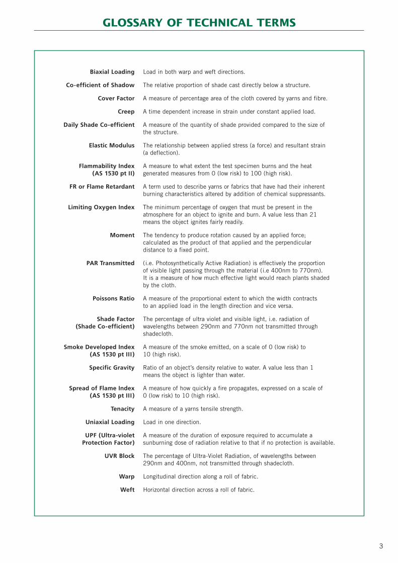
Biaxial Loading Load in both warp and weft directions.
Co-efficient of Shadow The relative proportion of shade cast directly below a structure.
Cover Factor A measure of percentage area of the cloth covered by yarns and fibre.
Creep A time dependent increase in strain under constant applied load.
Daily Shade Co-efficient A measure of the quantity of shade provided compared to the size of the structure.
Elastic Modulus The relationship between applied stress (a force) and resultant strain (a deflection).
Flammability Index A measure to what extent the test specimen burns and the heat (AS 1530 pt II) generated measures from 0 (low risk) to 100 (high risk).
FR or Flame Retardant A term used to describe yarns or fabrics that have had their inherent burning characteristics altered by addition of chemical suppressants.
Limiting Oxygen Index The minimum percentage of oxygen that must be present in the atmosphere for an object to ignite and burn. A value less than 21 means the object ignites fairly readily.
Moment The tendency to produce rotation caused by an applied force; calculated as the product of that applied and the perpendicular distance to a fixed point.
PAR Transmitted (i.e. Photosynthetically Active Radiation) is effectively the proportion of visible light passing through the material (i.e 400nm to 770nm).It is a measure of how much effective light would reach plants shadedby the cloth.
Poissons Ratio A measure of the proportional extent to which the width contracts to an applied load in the length direction and vice versa.
Shade Factor The percentage of ultra violet and visible light, i.e. radiation of (Shade Co-efficient) wavelengths between 290nm and 770nm not transmitted through
shadecloth.
Smoke Developed Index A measure of the smoke emitted, on a scale of 0 (low risk) to (AS 1530 pt III ) 10 (high risk).
Specific Gravity Ratio of an object’s density relative to water. A value less than 1 means the object is lighter than water.
Spread of Flame Index A measure of how quickly a fire propagates, expressed on a scale of (AS 1530 pt III ) 0 (low risk) to 10 (high risk).
Tenacity A measure of a yarns tensile strength.
Uniaxial Loading Load in one direction.
UPF (Ultra-violet A measure of the duration of exposure required to accumulate aProtection Factor) sunburning dose of radiation relative to that if no protection is available.
UVR Block The percentage of Ultra-Violet Radiation, of wavelengths between 290nm and 400nm, not transmitted through shadecloth.
Warp Longitudinal direction along a roll of fabric.
Weft Horizontal direction across a roll of fabric.

THE CONTENTS OF THIS TECHNICAL GUIDE ARE COPYRIGHT OCTOBER 2007. NO PART MAY BE REPRODUCED WITHOUT EXPLICIT PERMISSION.4
ProTEX is the masthead brand for a range of outdoortextiles and fabrics marketed by Nolan Warehouses. Thename, deliberately chosen as an alternative spelling of‘protects’, is a clear statement of its function. The word‘pro’ is an abbreviation of ‘professional’, or higheststandard; and ‘TEX’, a truncation of the word ‘textile’,which is the product descriptor. The ProTEX concept isvisually reinforced by the logo, with the umbrella shaped‘T’ providing protection from the elements, represented byburning sun and black storm clouds.
The brand itself is underpinned by a rigorous productdevelopment process, based on three basic principles:-
1. Selection of an appropriate standard, preferablyAustralian, but where this does not exist, the mostapplicable European, American or Japanese.
2. Rigorous and exhaustive testing, both in the laboratoryand the field, with particular emphasis on the resis-tance to the deleterious effects of ultra-violet light.
3. Provision of a warranty that states the product meetsthe chosen specification, and is fit for purpose for areasonably expected field life; provided it is selected,fabricated, installed and maintained, in accordancewith the advice provided in the ‘Technical Guides’.
The principal objective of this Technical Guide istherefore to fully document the above productdevelopment process for the ProTEX ranges of knittedshadecloth, and provide the relevant informationnecessary to satisfy the conditions of our warranty.
The adopted standard for material performance isAustralian Standard AS 4174 – 1994 “SyntheticShadecloth”, which in turn specifies Australian StandardAS 2001 “Method of Test for Textiles” for physicalproperties and light fastness. Testing has beenindependently undertaken to these standards by AWTATextile Testing.
The determination of engineering properties has beenundertaken by the consultants Izzat Consulting EngineersPty Ltd, based on laboratory testing undertaken by theUniversity of Newcastle. Design engineers usually requireestimates of the Elastic Properties of the material, andthese are provided for the commercial grade shadecloth‘Parasol’. Results of cyclic and creep testing at therecommended design working loads are also presented.
There is no standard in Australia or overseas, for productselection or installation. Whilst larger structures areusually designed by engineers, and constructed underengineering supervision, many smaller ones are not,which has been of concern to regulators and insurers,with good reason.
In late 1999, a young teenager was killed when ashadestructure, on which she and her friends werefrolicking, suddenly collapsed. The South AustralianCoroner recommended:-
“The creation of a complementary Standard (to theexisting Australian Standards for playgrounds) in relationto shade sail structures (which)… should make provisionfor at least the following factors:-
• standards for the design and construction, particularlydealing with footings, metal fabrication, weldingstandards, rust-proofing, strength of materials, etc;
• standards for tensioning of the structure, includingrecommended methods of performing and checkingthis aspect;
• standards for the frequency of maintenance, andparticularly retensioning;
• minimum height standards above play equipment to prevent access to the sail surfaces;
• standards for materials to be used;
• design standards for the layout of play equipment, and the placement of ground-level hazards such asborders;
• levels of signage required to warn of the dangers ofclimbing on the structure.
At the date of publication of this ‘Technical Guide’, sucha standard had not been prepared by Standards Australia.Consequently, included herein are a series of standarddetails and specifications for typical tensioned shadestructures of surface area less than fifty square metres.These provide the details recommended by the coroner,and have been prepared by Izzat Consulting Engineers PtyLtd. For a modest fee, the consultants can verify these tobe suited for a specific site, by checking local terrain (forwind loading risk) and ground conditions (for foundationdesign criteria), then issue an engineering certificate forthat particular location. The procedure for obtainingcertification is outlined within this guide.
For structures larger than fifty square metres in area,professional engineering advice specific to the projectshould be sought at the design stage. Some states (e.g.Queensland) require installers to be licensed.
The Building Code of Australia (BCA) has prescriptiverequirements for the fire hazard properties of materials,linings and surface finishes in buildings. Although subjectto interpretation, shadecloth structures may fall withinthe ambit of these regulations, and in this context aconservative approach has been adopted in this guide.
INTRODUCTION
• formula for calculation of the stresses involved, takinginto account such variables as wind, storms, etc;
THE CONTENTS OF THIS TECHNICAL GUIDE ARE COPYRIGHT OCTOBER 2007. NO PART MAY BE REPRODUCED WITHOUT EXPLICIT PERMISSION. 5
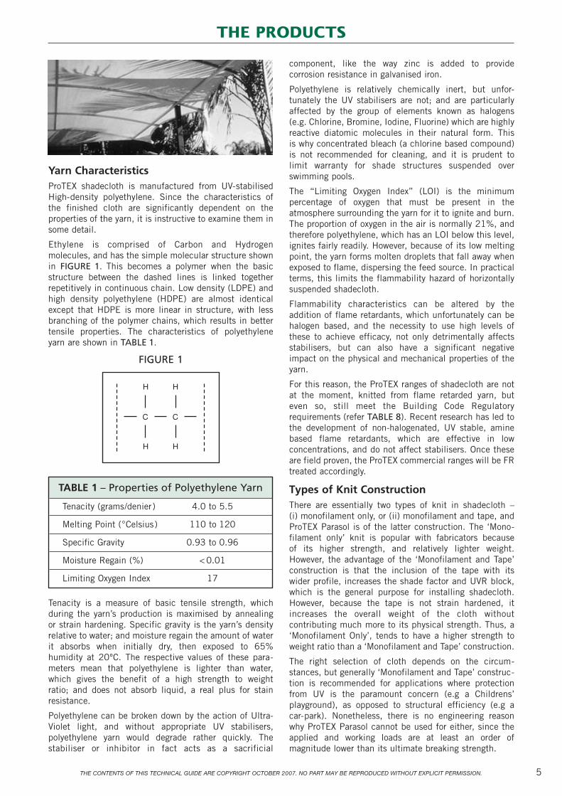
Yarn Characteristics ProTEX shadecloth is manufactured from UV-stabilisedHigh-density polyethylene. Since the characteristics ofthe finished cloth are significantly dependent on theproperties of the yarn, it is instructive to examine them insome detail.
Ethylene is comprised of Carbon and Hydrogenmolecules, and has the simple molecular structure shownin FIGURE 1. This becomes a polymer when the basicstructure between the dashed lines is linked togetherrepetitively in continuous chain. Low density (LDPE) andhigh density polyethylene (HDPE) are almost identicalexcept that HDPE is more linear in structure, with lessbranching of the polymer chains, which results in bettertensile properties. The characteristics of polyethyleneyarn are shown in TABLE 1.
FIGURE 1
Tenacity is a measure of basic tensile strength, whichduring the yarn’s production is maximised by annealing or strain hardening. Specific gravity is the yarn’s densityrelative to water; and moisture regain the amount of waterit absorbs when initially dry, then exposed to 65%humidity at 20ºC. The respective values of these para-meters mean that polyethylene is lighter than water,which gives the benefit of a high strength to weight ratio; and does not absorb liquid, a real plus for stainresistance.
Polyethylene can be broken down by the action of Ultra-Violet light, and without appropriate UV stabilisers,polyethylene yarn would degrade rather quickly. Thestabiliser or inhibitor in fact acts as a sacrificial
component, like the way zinc is added to providecorrosion resistance in galvanised iron.
Polyethylene is relatively chemically inert, but unfor-tunately the UV stabilisers are not; and are particularlyaffected by the group of elements known as halogens (e.g. Chlorine, Bromine, Iodine, Fluorine) which are highlyreactive diatomic molecules in their natural form. This is why concentrated bleach (a chlorine based compound)is not recommended for cleaning, and it is prudent tolimit warranty for shade structures suspended overswimming pools.
The “Limiting Oxygen Index” (LOI) is the minimumpercentage of oxygen that must be present in theatmosphere surrounding the yarn for it to ignite and burn.The proportion of oxygen in the air is normally 21%, andtherefore polyethylene, which has an LOI below this level,ignites fairly readily. However, because of its low meltingpoint, the yarn forms molten droplets that fall away whenexposed to flame, dispersing the feed source. In practicalterms, this limits the flammability hazard of horizontallysuspended shadecloth.
Flammability characteristics can be altered by theaddition of flame retardants, which unfortunately can behalogen based, and the necessity to use high levels ofthese to achieve efficacy, not only detrimentally affectsstabilisers, but can also have a significant negativeimpact on the physical and mechanical properties of theyarn.
For this reason, the ProTEX ranges of shadecloth are notat the moment, knitted from flame retarded yarn, buteven so, still meet the Building Code Regulatoryrequirements (refer TABLE 8). Recent research has led tothe development of non-halogenated, UV stable, aminebased flame retardants, which are effective in lowconcentrations, and do not affect stabilisers. Once theseare field proven, the ProTEX commercial ranges will be FRtreated accordingly.
Types of Knit ConstructionThere are essentially two types of knit in shadecloth – (i) monofilament only, or (ii) monofilament and tape, andProTEX Parasol is of the latter construction. The ‘Mono-filament only’ knit is popular with fabricators because of its higher strength, and relatively lighter weight.However, the advantage of the ‘Monofilament and Tape’construction is that the inclusion of the tape with itswider profile, increases the shade factor and UVR block,which is the general purpose for installing shadecloth.However, because the tape is not strain hardened, itincreases the overall weight of the cloth withoutcontributing much more to its physical strength. Thus, a‘Monofilament Only’, tends to have a higher strength toweight ratio than a ‘Monofilament and Tape’ construction.
The right selection of cloth depends on the circum-stances, but generally ‘Monofilament and Tape’ construc-tion is recommended for applications where protectionfrom UV is the paramount concern (e.g a Childrens’playground), as opposed to structural efficiency (e.g a car-park). Nonetheless, there is no engineering reasonwhy ProTEX Parasol cannot be used for either, since theapplied and working loads are at least an order ofmagnitude lower than its ultimate breaking strength.
TABLE 1 – Properties of Polyethylene Yarn
Tenacity (grams/denier) 4.0 to 5.5
Melting Point (°Celsius) 110 to 120
Specific Gravity 0.93 to 0.96
Moisture Regain (%) < 0.01
Limiting Oxygen Index 17
THE PRODUCTS

THE CONTENTS OF THIS TECHNICAL GUIDE ARE COPYRIGHT OCTOBER 2007. NO PART MAY BE REPRODUCED WITHOUT EXPLICIT PERMISSION.6
PRODUCT FEATURES
✓ UV Stabilised Yarn
✓ Up to 95% UVR Block
✓ Colour Fast
✓ High Strength
✓ Heat Set
✓ Abrasion Resistant
✓ Ten Year Limited Warranty
THE PRODUCTS (continued)
Roll length: 50 metres
Roll diameter: 38cm
Total roll weight: 50 kilograms
Colours available: Black, Dark Green, Sand (for colour samples refer inside back cover)
Premium Grade ShadeclothBrandname: ProTEX ‘Sombrero’
Construction: Monofilament
Weight: 240 grams/square metre (± 5%)
Width: 4.0 metres
Commercial Grade Shadecloth
ProTEX ‘Parasol’ shadecloth is knitted with a lock-stitchconstruction, which provides dimensional stability andminimises unravelling when cut. It has a high strengthto weight ratio, and can be easily tensioned in both warpand weft directions. All finished product is stentored, orheat set, to minimise shrinkage, and to improve lay-flatcharacteristics, which can be a significant factor inreducing cutting and fabrication costs.
Brandname: ProTEX ‘Parasol’
Construction: Monofilament and tape.
Weight: 325 grams/square metre (± 5%)
Width: 3.0 metres
Roll length: 50 metres
Roll diameter: 37cm
Total roll weight: 50 kilograms
Identifying marks: None. Identifiable by tape insert in weft direction
Colours available: (Ex-stock) – Beach Sand, Red, Harvest, Forest Green, Terracotta, Ocean Blue, Navy, Ivory, Gun Metal, Black. (Indent only) – Yellow, Sky Blue, Foggy Grey, Chestnut Brown, Silver
(for colour samples refer inside back cover)
THE CONTENTS OF THIS TECHNICAL GUIDE ARE COPYRIGHT OCTOBER 2007. NO PART MAY BE REPRODUCED WITHOUT EXPLICIT PERMISSION. 7
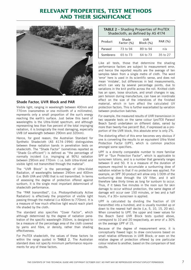
Shade Factor, UVR Block and PARVisible light, ranging in wavelength between 400nm and770nm (nanometres or one millionth of a millimetre),represents only a small proportion of the sun’s energyreaching the earth’s surface. Just below this band ofwavelengths is the Ultra-Violet spectrum, and althoughrepresenting less than five percent of the total impingingradiation, it is biologically the most damaging, especiallyUVB (of wavelength between 290nm and 320nm).
Hence, for good reason, the Australian Standard forSynthetic Shadecloth (AS 4174 -1994) distinguishesbetween these radiation bands in penetration tests onshadecloth. The “Shade Factor” (sometimes reported as“Shade Co-efficient”) is defined as “the percentage ofnormally incident (i.e. impinging at 90%) radiationbetween 290nm and 770nm ( i.e. both Ultra-Violet andvisible light) not transmitted through the material”.
The “UVR Block” is the percentage of Ultra-VioletRadiation, of wavelengths between 290nm and 400nm(i.e. Both UVA and UVB) that is not transmitted. In termsof assessing the degree of protection offered againstsunburn, it is the single most important determinant ofshadecloth performance.
The “PAR transmitted”, (i.e. Photosynthetically ActiveRadiation) is effectively the proportion of visible lightpassing through the material (i.e 400nm to 770nm). It isa measure of how much effective light would reach plantlife shaded by the cloth.
The standard also specifies “Cover Factor”, whichalthough determined by the degree of radiation pene-tration of the specific wavelength 350nm, is designed tobe a measure of the percentage area of the cloth coveredby yarns and fibre, or density, rather than shadingeffectiveness.
For ProTEX shadecloth, the values of these factors liewithin the range quoted in TABLE 2. The Australianstandard does not specify minimum performance require-ments for any of these factors.
Like all tests, those that determine the shadingperformance factors are subject to measurement error,and hence the reported results are the average of tensamples taken from a single metre of cloth. The word‘error’ here is used in its scientific sense, and does notmean ‘mistake’, but differences in test measurements,which can vary by several percentage points, due tovariations in the knit profile across the roll. Knitted clothhas an open, loose structure, and small changes in say,yarn tension during manufacture, can have an inordinateeffect on the size of the interstices of the finishedmaterial, which in turn affect the calculated UVprotection factors. This is further exacerbated by variationbetween production batches.
For example, the measured results of UVR transmission intwo separate tests on the same colour (proTEX ParasolBeach Sand) undertaken on different dates, varied bymore than twenty-five percent! But, if expressed as a pro-portion of the UVR block, this absolute error is only 2%.
The distorting effect of this error becomes very obvious ifone is converting the results to an equivalent Ultra VioletProtection Factor (UPF), which is common practiceamongst some specifiers.
UPF is a directly comparable number to more familiarSPF or “Sun Protection Factor”, which is applicable tosunscreen lotions, and is a number that generally rangesbetween 0 and 50. It is a measure of the duration ofexposure required to accumulate a sunburning dose ofradiation relative to that if no protection was applied. Forexample, an SPF 30 product will allow only 1/30th of thesunburning dose through the UV filter, and it willtherefore take thirty times as long for sunburn to occur.Thus, if it takes five minutes in the noon sun for skindamage to occur without protection, the same degree ofdamage will occur over 150 minutes, or two and a halfhours, if a 30+ sunscreen is applied.
UPF is calculated by dividing the fraction of UVtransmitted into a hundred, and is usually rounded up ordown to the nearest half decile (i,e, 5, 10, 15, 20 etc).When converted to UPF, the upper and lower values forthe Beach Sand UVR Block tests quoted above,correspond to 10 and 20 respectively, an error of ± 30%on the average UPF of 15.
Because of the degree of measurement error, it isconceptually flawed logic to draw conclusions based onsmall relative differences in UVR Block; or even on therelative degree of protection offered by one particularcolour relative to another, based on the comparison of testresults.
TABLE 2 – Shading Properties of ProTEXShadecloth, as defined by AS 4174
ProductShade UVR
Factor (%) Block (%) PAR (%)
Parasol 73 to 94 89 to 94 n/a
Sombrero 65 to 73 64 to 73 35 to 27
RELEVANT PROPERTIES, TEST METHODSAND THEIR SIGNIFICANCE
THE CONTENTS OF THIS TECHNICAL GUIDE ARE COPYRIGHT OCTOBER 2007. NO PART MAY BE REPRODUCED WITHOUT EXPLICIT PERMISSION.8
RELEVANT PROPERTIES, TEST METHODS AND THEIR SIGNIFICANCE (cont.)
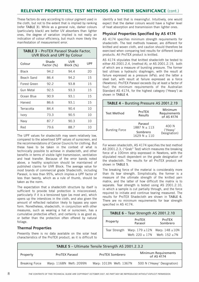
These factors do vary according to colour pigment used inthe cloth, but not to the extent that is implied by ranking(refer TABLE 3). While as a general rule, darker colours(particularly black) are better UV absorbers than lighterones, the degree of variation implied is not really anindication of colour efficiency, but much more likely themanifestation of measurement error.
The UPF values for shadecloth may seem relatively low,compared to the advertised SPF values of sunscreen, andthe recommendations of Cancer Councils for clothing. Butthese have to be taken in the context of what istechnically possible to achieve in shadecloth, and otherbenefits in terms of visible light transmission, ventilationand heat transfer. Because of the error bands notedabove, a healthy scepticism should be maintained ofpublished claims for UVR Block. The average value formost brands of commercial grade Shadecloth, includingParasol, is less than 95%, which implies a UPF factor ofless than twenty, which as a rule of thumb, should betaken as the norm.
The expectation that a shadecloth structure by itself issufficient to provide total protection is misconceived,particularly if it is a tensioned type (as most are), whichopens up the interstices in the cloth, and also given theamount of reflected radiation likely to bypass any openform. Nonetheless, shadecloth, in conjunction with othermeasures, such as wearing a hat or sunscreen, has acumulative protective effect, and certainly is as good as,or better than the protection often offered by naturalfoliage.
Thermal PropertiesPresently there is no data available on the solar heatcharacteristics of the ProTEX product, as it is difficult to
identify a test that is meaningful. Intuitively, one wouldexpect that the darker colours would have a higher levelof heat absorption and transmission than lighter ones.
Physical Properties Specified by AS 4174 AS 4174 specifies minimum strength requirements forshadecloth. The test methods however, are different forknitted and woven cloth, and caution should therefore beexercised when comparing test results for different brandproducts. All ProTEX product is knitted.
AS 4174 stipulates that knitted shadecloth be tested toeither AS 2001.2.4, (method A), or AS 2001.2.19, bothof which are a measure of bursting pressure. The formertest utilises a hydraulic diaphragm, with the result atfailure expressed as a pressure (kPa); and the latter asteel ball, with result at failure expressed as a force(Newtons). ProTEX Parasol exceeds (by at least a factor offour) the minimum requirements of the AustralianStandard AS 4174, for the highest category (‘Heavy’) asshown in TABLE 4.
For woven shadecloth, AS 4174 specifies the test methodAS 2001.2.3, (“Grab” Test) which measures the breakingforce of a 100mm strip expressed in Newtons, with thestipulated result dependent on the grade designation ofthe shadecloth. The results for all ProTEX product areshown in TABLE 5.
The breaking force of the material is considerably morethan its tear strength. Simplistically, the former is ameasure of the ultimate strength of the knitted yarnmatrix, and the latter of how difficult the matrix is toseparate. Tear strength is tested using AS 2001.2.10, in which a sample is cut partially through, and the forcerequired to initiate and continue tearing measured. Theresults for ProTEX Shadecloth are shown in TABLE 6.There are no minimum requirements for tear strengthspecified in AS 4174.
TABLE 4 – Bursting Pressure AS 2001.2.19
ProTEXMinimum
Test MethodResults
Requirementsof AS 4174
Parasol400 N
Bursting Force1887 N ± 113
(‘Heavy’Sombrero
1629 N ± 110Designation)
TABLE 5 – Ultimate Tensile Strength AS 2001.2.3.2
Property ProTEX Parasol ProTEX Sombrero Minimum Requirements of AS 4174
Breaking Force Warp: 1168N Weft: 2099N Warp: 1013N Weft: 1367N 500 N (‘Heavy’ Designation)
TABLE 6 – Tear Strength AS 2001.2.10
Property ProTEX ProTEXParasol Sombrero
Tear Strength Warp: 179 ±12N Warp: 148 ±10NWeft: 220 ± 17N Weft: 152 ±7N
TABLE 3 – ProTEX Parasol Shade Factor, UVR Block and UPF by Colour
ColourShade UVR
Factor (%) Block (%) UPF
Black 94.2 94.4 20
Beach Sand 86.4 94.2 15
Forest Green 92.2 93.8 15
Gun Metal 92.5 93.3 15
Ocean Blue 90.9 93.1 15
Harvest 86.6 93.1 15
Terracotta 84.4 90.4 10
Ivory 73.3 90.5 10
Navy 87.7 90.3 10
Red 79.6 88.7 10

THE CONTENTS OF THIS TECHNICAL GUIDE ARE COPYRIGHT OCTOBER 2007. NO PART MAY BE REPRODUCED WITHOUT EXPLICIT PERMISSION. 9
The range of results (i.e between the plus and minusvalues) shown in TABLE 4 and TABLE 6 are included toillustrate the extent of ‘error’ that can be expected in testsof this nature. As with the estimation of UPF, the effect oferror becomes particularly magnified if one subtracts oneset of results from another, as occurs in the assessmentof the effects of ultra-violet light.
AS 4174 specifies that shadecloth retain at least 80% ofits initial breaking strength after exposure to an intenseUV radiation source for 2000 hours. To ensurecompliance with this requirement, samples of ProTEXParasol shadecloth were exposed to a 500 Watt MBTFlamp for 2016 hours, and then tested for strength loss.The results are summarised in TABLE 7.
Paradoxically, HDPE yarn can experience some increasein strength under the action of UV radiation, but anincrement in one direction, and a decrement in the other,as implied by the results in TABLE 7, can be discountedas physically improbable. Based on the standard deviation
TABLE 7 – Percent increment (+)or decrement (–) in strength after
UV exposure (ProTEX Parasol)
Tensile Strength Bursting Force Tear Strength AS 2001.2.3.2 AS 2001.2.19 AS 2001.2.10
Warp: +6.3% Warp: +12.2% Warp: –2.2%Weft: –5.3% Weft: n/a Weft: +11.4%
of these results, a statistical analysis (Student ‘t’ test)shows them to be ‘not significant’, and therefore shouldbe discounted. Thus, there is no evidence of strengthdegradation due to UV exposure in ProTEX Parasol underthe conditions of the test, estimated (very roughly) to beequivalent to six to eight months field life.
Chemical PropertiesHigh density Polyethylene is resistant to most acids andalkalis, and fungal attack. It does not absorb water, whichis a significant factor in resisting staining and inhibitingmildew growth. These characteristics make HDPE ideal asa base yarn for a lightweight, strong shadecloth.
A summary of the chemical resistance of HDPE iscontained in APPENDIX D. This is general informationonly, since colour pigment may be affected by a particularchemical, even though HDPE itself may not.
HDPE has only a weak resistance to halogens, such aschlorine; and halogenated hydro-carbons. It is alsoaffected by strong oxidising agents, such as hydrogenperoxide; chlorox (bleach); and some alcohols.
Using such chemicals for cleaning should be avoided. Dirtor mildew is usually the result of contaminants caught inthe interstices of the cloth, and should be easily removedusing a high pressure hose. For stubborn stains, scrubwith a brush and a weak solution of household detergent.
Careful consideration should be given to the environmentin which ProTEX shadecloth is used. For example, whensuspended over a swimming pool, it will be exposed tochlorine emissions, and its effective life may be reduced.
StandardsThere are more than twelve separate Australian Standardfire tests that are applicable to textiles. Apart from theplethora of choice, the difficulty is the selection of onethat is appropriate to the expected use of the material.
Given that shadecloth is invariably used in an externalenvironment, either as a self-supporting structure, orattached to a building, it is logical to use tests that aredesigned to reflect that environment. There are alsobuilding regulations, applicable to shadecloth structures,that specify results for AS 1530 pt III.
This test is intended primarily for building components,but is widely used to test textiles, despite questions of itsrelevance to thin, planer forms. There is also someconfusion in the marketplace, regarding the meaning ofthe term ‘FR’, or ‘Flame Retardant’, in which contextoverseas test methods are often quoted. These are usually‘strip burn’ type tests, similar to AS 1530 pt II.
For these reasons, the appropriate selection of Australiantests for shadecloth would be both AS 1530 pt III, and AS 1530 pt II.
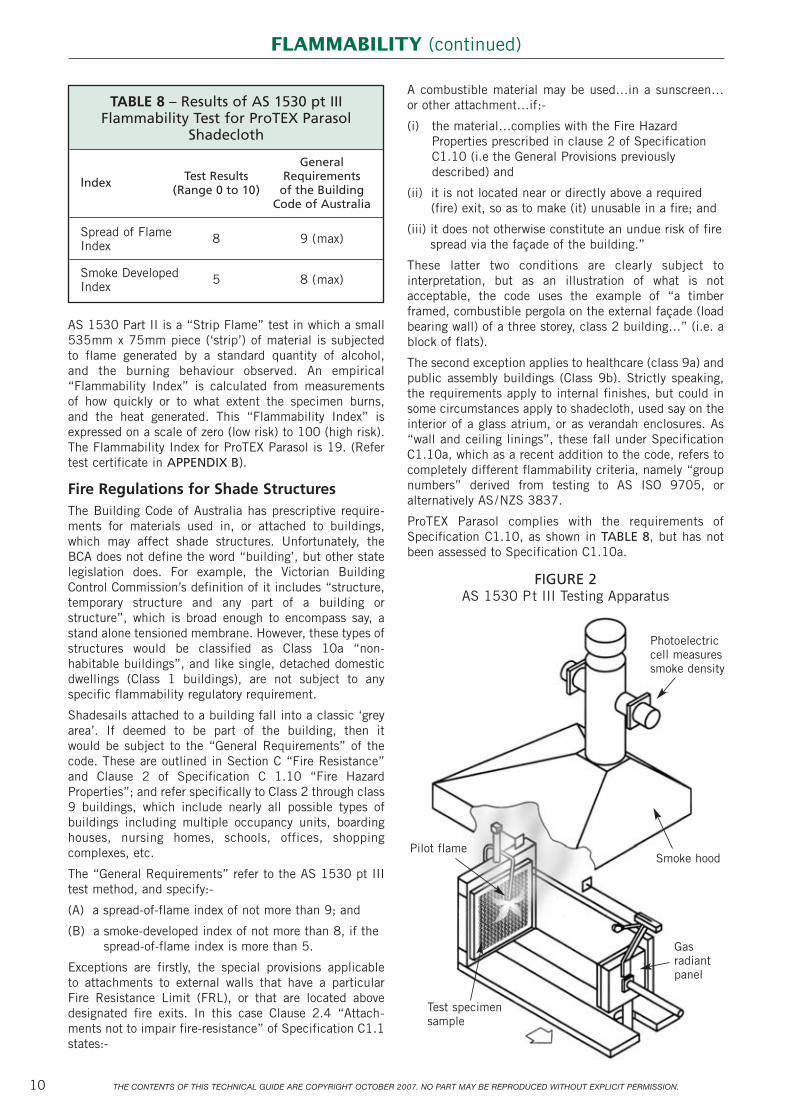
Description of the AS 1530 pt II and pt III TestsAS 1530 pt III is designed to assess the full gambit ofcombustion risk, namely ignitability, flame propagation,heat release, and smoke emitted.
The test entails subjecting a vertically mounted 600mmx 600mm sample to both radiated heat and an ignitionsource, and its burning behaviour from ignition toextinction is observed. The intense radiated heat causesthe sample to emit volatile substances, or even melt, andthe ignition source ensures that these burn, refer FIGURE2. The results are expressed in the form of four indices,sometimes termed “Early Fire Hazard Indices”, not to beconfused with the “Flammability Index” of AS 1530 pt II.
Only two of these indices – the “Spread of Flame Index”,and the “Smoke Developed Index” are referred to in theBuilding Code of Australia. The “Spread of Flame Index”is a measure of how quickly a fire propagates, expressedon a scale of 0 to 10. The higher the value, the worse theresult. The “Smoke Developed Index” is also expressed ona scale of 0 to 10, with each increment representing abifold increase of the smoke emitted. The results of AS 1530 pt III flammability tests for ProTEX Parasol are summarised in TABLE 8, and copies of the testcertificates attached as APPENDIX B.
FLAMMABILITY
THE CONTENTS OF THIS TECHNICAL GUIDE ARE COPYRIGHT OCTOBER 2007. NO PART MAY BE REPRODUCED WITHOUT EXPLICIT PERMISSION.10
AS 1530 Part II is a “Strip Flame” test in which a small535mm x 75mm piece (‘strip’) of material is subjected to flame generated by a standard quantity of alcohol, and the burning behaviour observed. An empirical“Flammability Index” is calculated from measurements of how quickly or to what extent the specimen burns, and the heat generated. This “Flammability Index” isexpressed on a scale of zero (low risk) to 100 (high risk).The Flammability Index for ProTEX Parasol is 19. (Refertest certificate in APPENDIX B).
Fire Regulations for Shade Structures The Building Code of Australia has prescriptive require-ments for materials used in, or attached to buildings,which may affect shade structures. Unfortunately, theBCA does not define the word “building’, but other statelegislation does. For example, the Victorian BuildingControl Commission’s definition of it includes “structure,temporary structure and any part of a building orstructure”, which is broad enough to encompass say, astand alone tensioned membrane. However, these types ofstructures would be classified as Class 10a “non-habitable buildings”, and like single, detached domesticdwellings (Class 1 buildings), are not subject to anyspecific flammability regulatory requirement.
Shadesails attached to a building fall into a classic ‘greyarea’. If deemed to be part of the building, then it would be subject to the “General Requirements” of thecode. These are outlined in Section C “Fire Resistance”and Clause 2 of Specification C 1.10 “Fire HazardProperties”; and refer specifically to Class 2 through class9 buildings, which include nearly all possible types ofbuildings including multiple occupancy units, boardinghouses, nursing homes, schools, offices, shoppingcomplexes, etc.
The “General Requirements” refer to the AS 1530 pt IIItest method, and specify:-
(A) a spread-of-flame index of not more than 9; and
(B) a smoke-developed index of not more than 8, if thespread-of-flame index is more than 5.
Exceptions are firstly, the special provisions applicable to attachments to external walls that have a particular Fire Resistance Limit (FRL), or that are located abovedesignated fire exits. In this case Clause 2.4 “Attach-ments not to impair fire-resistance” of Specification C1.1states:-
A combustible material may be used…in a sunscreen…or other attachment…if:-
(i) the material…complies with the Fire HazardProperties prescribed in clause 2 of SpecificationC1.10 (i.e the General Provisions previouslydescribed) and
(ii) it is not located near or directly above a required(fire) exit, so as to make (it) unusable in a fire; and
(iii) it does not otherwise constitute an undue risk of firespread via the façade of the building.”
These latter two conditions are clearly subject tointerpretation, but as an illustration of what is notacceptable, the code uses the example of “a timberframed, combustible pergola on the external façade (loadbearing wall) of a three storey, class 2 building…” (i.e. ablock of flats).
The second exception applies to healthcare (class 9a) andpublic assembly buildings (Class 9b). Strictly speaking,the requirements apply to internal finishes, but could insome circumstances apply to shadecloth, used say on theinterior of a glass atrium, or as verandah enclosures. As“wall and ceiling linings”, these fall under SpecificationC1.10a, which as a recent addition to the code, refers tocompletely different flammability criteria, namely “groupnumbers” derived from testing to AS ISO 9705, oralternatively AS/NZS 3837.
ProTEX Parasol complies with the requirements ofSpecification C1.10, as shown in TABLE 8, but has notbeen assessed to Specification C1.10a.
FIGURE 2AS 1530 Pt III Testing Apparatus
FLAMMABILITY (continued)
TABLE 8 – Results of AS 1530 pt IIIFlammability Test for ProTEX Parasol
Shadecloth
General
Index Test Results Requirements(Range 0 to 10) of the Building
Code of Australia
Spread of Flame 8 9 (max)Index
Smoke Developed 5 8 (max)Index
Photoelectriccell measuressmoke density
Smoke hoodPilot flame
Gasradiantpanel
Test specimensample
Based on our experience, and analysis of the testingdescribed, the consultants Izzat Pty Ltd have estimatedProTEX Parasol’s elastic material properties forengineering design purposes. The estimates are listed inTABLE 9 and TABLE 10. Caution should be used whenusing these figures in finite element analysis, as criticalassumptions are made on membrane behaviour that mayaffect computational accuracy. If in any doubt as to thevalidity of these assumptions, the consultants should becontacted directly.
Where:- The stress ratio is the ratio of tension in thelength (x) direction to tension in the width (y)direction.
Ex (kN/m) is the tensile elastic modulus in the length (or warp) direction
Ey (kN/m) is the tensile elastic modulus in the width (or weft) direction
v is Poisson’s ratio in either direction
The first assumption is the estimate of Poissons Ratio,which is a measure of the proportional extent to which the width contracts for an applied load in the lengthdirection, and vice versa. This theoretically could bemeasured from standard uniaxial tests, but in practicethis is not easy due to the test sample shape, and thedistorting effect on lateral deflection of the supportingclamps of the testing apparatus. The respective poissonsratios in each direction also vary in the biaxial loadingcase, dependent on the relative applied tensions. Thevalues adopted are based on field experience, and biaxialtest results for similar materials.
The second assumption relates to the estimates of ElasticModulus, and the range shown is designed to simulate thecontracting effect of biaxial loading. However, theprospect of significant further stiffening of the material,demonstrated by the cyclic loading tests, should be takeninto account and the sensitivity of the consequentchanges to these E values should be tested in any finiteelement model.
THE CONTENTS OF THIS TECHNICAL GUIDE ARE COPYRIGHT OCTOBER 2007. NO PART MAY BE REPRODUCED WITHOUT EXPLICIT PERMISSION. 11
The tensile strength test, specified by AS 4174,measures ultimate loads, which in practice is notparticularly useful. This is because at failure, the materialis extended up to 40%, and so strain hardened as to berendered useless. For this reason, the safe working loadsapplied to the cloth in tensioning are very much less thanthe ultimate. By way of example, ProTEX Parasol (underuniaxial loading) has a rated ultimate tensile strength of 12 kN/m (kiloNewtons/metre) in the warp direction,and 21 kN/m in the weft. However, a typical value ofpretension used in common shade structures is 0.25kN/m, which is less than 1.5% of the ultimate loads.
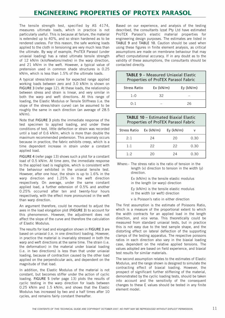
A typical stress/strain curve for expected range appliedworking loads between zero and 3.0 kN/m is shown onFIGURE 3 (refer page 12). At these loads, the relationshipbetween stress and strain is linear, and very similar inboth the warp and weft directions. At this range ofloading, the Elastic Modulus or Tensile Stiffness (i.e. theslope of the stress/strain curve) can be assumed to beroughly the same in each direction (an average of 28.5kN/m).
Note that FIGURE 3 plots the immediate response of thetest specimen to applied loading, and under theseconditions of test, little deflection or strain was recordeduntil a load of 0.6 kN/m, which is more than double themaximum recommended pretension. This anomaly occursbecause in practice, the fabric exhibits creep, which is atime dependent increase in strain under a constantapplied load.
FIGURE 4 (refer page 13) shows such a plot for a constantload of 0.5 kN/m. At time zero, the immediate responseto the applied load is negligible, which is consistent withthe behaviour exhibited in the uniaxial tensile test.However, after one hour, the strain is up to 1.6% in thewarp direction and 1.25% in the weft directionrespectively. On average, under the same constantapplied load, a further extension of 0.5% and another0.25% occurred after ten and twenty-four hoursrespectively, with the effect more pronounced in the weftthan warp direction.
An argument therefore, could be mounted to adjust theaxes in the load elongation plot (FIGURE 3) to account forthis phenomenon. However, the adjustment does notaffect the slope of the curve and therefore the calculationof Elastic Modulus.
The results for load and elongation shown in FIGURE 3 arebased on uniaxial (i.e. in one direction) loading. However,in practice the material is invariably stressed in both thewarp and weft directions at the same time. The strain (i.e.the deformation) in the material under biaxial loading (i.e. in two directions) is less than that under uniaxialloading, because of contraction caused by the other loadapplied on the perpendicular axis, and dependent on themagnitude of that load.
In addition, the Elastic Modulus of the material is notconstant, but becomes stiffer under the action of cyclicloading. FIGURE 5 (refer page 13) plots the results ofcyclic testing in the warp direction for loads between0.25 kN/m and 1.5 kN/m, and shows that the ElasticModulus has increased by two and a half times after 10cycles, and remains fairly constant thereafter.
TABLE 9 – Measured Uniaxial ElasticProperties of ProTEX Parasol Fabric
Stress Ratio Ex (kN/m) Ey (kN/m)
1:0 32 –
0:1 – 26
TABLE 10 – Estimated Biaxial ElasticProperties of ProTEX Parasol Fabric
Stress Ratio Ex (kN/m) Ey (kN/m) v
2:1 24 20 0.30
1:1 22 22 0.30
1:2 20 24 0.30
ENGINEERING PROPERTIES OF PROTEX PARASOL

12 THE CONTENTS OF THIS TECHNICAL GUIDE ARE COPYRIGHT OCTOBER 2007. NO PART MAY BE REPRODUCED WITHOUT EXPLICIT PERMISSION.
FIGURE 3
Load vs Percentage Elongation Graph
3.0
2.7
2.4
2.1
1.8
1.5
1.2
0.9
0.6
0.3
0.00.0 1.0 2.0 3.0 4.0 5.0 6.0 7.0 8.0 9.0 10.0
Percentage Elongation (%)
Load
(kN
/m)
Average WarpAverage Weft
ENGINEERING PROPERTIES OF PROTEX PARASOL (cont.)
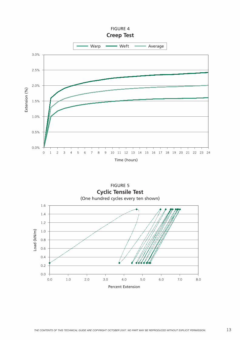
THE CONTENTS OF THIS TECHNICAL GUIDE ARE COPYRIGHT OCTOBER 2007. NO PART MAY BE REPRODUCED WITHOUT EXPLICIT PERMISSION. 13
Time (hours)
Percent Extension
Exte
nsi
on
(%
)
Load
(kN
/m)FIGURE 4
Creep Test
FIGURE 5
Cyclic Tensile Test(One hundred cycles every ten shown)
Warp Weft Average
3.0%
2.5%
2.0%
1.5%
1.0%
0.5%
0.0%
1.6
1.4
1.2
1.0
0.8
0.6
0.4
0.2
0.0
0 1 2 3 4 5 6 7 8 9 10 11 12 13 14 15 16 17 18 19 20 21 22 23 24
0.0 1.0 2.0 3.0 4.0 5.0 6.0 7.0 8.0

14 THE CONTENTS OF THIS TECHNICAL GUIDE ARE COPYRIGHT OCTOBER 2007. NO PART MAY BE REPRODUCED WITHOUT EXPLICIT PERMISSION.
GeneralWhen cut, ProTEX shadecloth will fray if the edge is notseamed, particularly if the exposed edge is allowed to flapin the wind. For strength and aesthetic reasons, the edgeand join seam should be overlapped twice, and preferablydouble stitched.
A “lock-stitch” is preferred to a “chain-stitch”. Althoughthe latter has more “give”, it can have an abrasive effecton the sewing thread, and in failure tends to “un-zip”along the underside.
Although once widely used, cotton thread, or a poly-cotton blend is not recommended. Cotton is not aparticularly durable material for use in an outdoorenvironment. It does not have a very high strength, andwithout treatment, frays, rots and mildews. This is whyone sees evidence of seam failure on jobs where the fabricstill has a lot of life left.
The use of a UV stabilised, 100% polyester thread (suchas "SUNGUARD") has proved to be durable in the field.Polyester, however does lose strength under the action ofsunlight. Although tests (refer APPENDIX C) show thatsize B138 is probably adequate, the heavier size B208 isrecommended.
Recently, PTFE (PolyTetraFluorEthylene) thread, (such as“PROFILEN”) has started to become more widely used.Although costly, it has far more durability and a muchlonger life than other types of thread.
Non-Tension ApplicationsEven in non-tension applications, the cloth will be subjectto windload, which will induce stress in the cloth and theisolated fixing points. For this reason, one must ensurethat all fixing points are structurally adequate, andfittings soundly secured. Caution should be exercisedwhen connecting to a stud frame or wall of a building, asthese have limited resistance to overturning moment, andthere is a real risk of structural damage occurring in ahigh wind. Preferably, the sail should be supportedindependently. It should also be taken down while thelikelihood of strong wind conditions exist, to avoid thepotentially high loads at the fixing locations.
Ideally the cloth should be supported uniformly along thewhole of its edge. Even with isolated connecting points, itis possible to convert the concentrated load to a moreuniformly distributed load in the fabric. There are tworecommended ways of doing this.
Method one is to fold and sew 50mm of UV stabilised,reinforced rayon seat belt webbing along the edge, andpunch SP4 eyelets through this reinforcing at the desiredlocations, as shown on FIGURE 6.
Method two is to sew a six millimetre nylon cord along the edge trim, and use Plaspaline® Ropeclamps at thedesired fixing locations, as shown on FIGURE 7. Thismethod is more flexible, as the clamps do not penetratethe fabric and can be easily relocated.
Where the cloth is to be fixed using timber battens, thesupporting edge should be wrapped at least once aroundthe batten before nailing. Even then, reliance is being
placed on the friction induced between the batten and thesubstrate. Any loosening of the batten over time willconcentrate stress at the nail locations, possibly leadingto tear.
FIGURE 6
FIGURE 7
FIGURE 8
25mmPlaspiline
Clamp
6mm diameter Cord
DoubleStitching
25mm
Folded 50mm Seat-belt WebbingSP4 eyelet
(21mm diameter )
Stitch
FABRICATION
Aluminium ChannelPlastic Insert Piece
Shadecloth

The V-grip V136 fastening system® is another method ofattachment, which provides a clean, tight professionallooking finish. The system entails fixing an aluminiumsection and inserting a locking strip between it and theshadecloth, as shown in FIGURE 8. The system has theadvantage of allowing the cloth to be easily removed orreplaced, and no seaming of the edge is required. Theshadecloth can be installed then cut on site.
Tension ApplicationsBecause of its higher inherent strength, only Parasol fromthe ProTEX range should be used in tension structures. It is important that it is not overtensioned, if the shapeand elasticity of the material is to be retained. The higherthe load, the greater the risk of deformation or saggingover time. The maximum recommended pre-stress is 0.25 kN/m in both the warp and weft directions.
Tension structures rely on applied force for both shapingthe fabric, and structural integrity. The applied forces andwindload on the supports can be significant, andprofessional engineering advice should always be soughtat the design stage.
Pre-stress in the cloth is invariably induced by tensioninga cable along the edge of the fabric, which is cut in acurved shape. The flatter the curve, the higher the tensionin the cable, which is equal to the radius of curvaturetimes the reactive stress of the cloth (Refer APPENDIX E).The reactive stress applied by cloth is dependent on itsdeformation or strain, the characteristics of which can bedifferent in the warp and weft directions. This can be acomplicating factor in design, and one of the advantagesof ProTEX Parasol is that its stress/strain characteristicsare similar in each direction.
For example, to minimise lateral loading at supports, it isdesirable that the tension in the cable is constant (whichit will be anyway if it is continuous). Most tensionstructures are designed for the condition of equal stressin both warp and weft directions, in which case forProTEX Parasol, the relative strain is about equal, thusmaking patterning that much simpler.
This is because, under these design conditions, thefinished radius of curvature will be equal for each spanand a theoretical engineering relationship exists betweencable tension, reactive stress and tensioned chord depthfor any given span (refer APPENDIX E). This may proveuseful as a guide for setting out, or estimating the appliedstress or cable tension in the finished structure.
15THE CONTENTS OF THIS TECHNICAL GUIDE ARE COPYRIGHT OCTOBER 2007. NO PART MAY BE REPRODUCED WITHOUT EXPLICIT PERMISSION.
There is a simpler method. For the same design con-ditions, the ratio of depth to span can be approximated bythe formula:-
d = kL2 where: d = depth at mid-point L = span and k is a constant.
If, for the longest span, the ratio of d to L is assumed tobe 0.1, the proportional value of the expected finisheddepth of other spans can be determined by multiplyingthis longest span depth by the ratio of the square of thelengths, as follows:-
dn = d1 x (Ln/L1)2
where dn and Ln refer to the depth and lengthrespectively of any other span. This rule of thumb mayprove useful for initial shaping, determining expectedshading envelopes of proposed designs, or estimating therelative quantities of material required.
There are a number of ways of making a sheath for atensioning cable. The simplest is to incorporate it into theedge seam. Another method is to create a pouch usingseat belt webbing, or use the webbing itself as thetensioning medium. 50mm UV stabilised rayon seat beltwebbing has a breaking strength of 20kN. It is thereforesuited for use in smaller structures (i.e. <50m2). Thewebbing can be continuous, and neatly looped at thecorners to provide an attachment point to a turnbuckle orother tensioning device. One problem with this method isthat the webbing is a lot stiffer than the shadecloth itself,and because of this, the sail can become baggy as theshadecloth deforms with time.
Design and Installation of SupportsThe force of wind should not be underestimated, and isthe reason the supporting structures and cables of large area shadesails appear so robust. Professionalengineering advice should always be sought on the design of the supports.
Wind design stresses are in the order of 1.5kN/m, whichis still very much less than the ultimate stress of thecloth. Typically then, the wind failure mode is loss ofelasticity rather than tear or burst. Failure can also occurfor other reasons, such as the accumulation of hail.
Shadesails are invariably attached by a corner to a columnor other fitting, and the treatment of these requires somethought. It is crucial that the tensile load in the cable istransferred directly to the supports. The reactive stress inthe fabric tends to drag it away from the supports, andreinforcement at these corner points is recommended.
Connection to a column without a backstay results in asignificant bending or overturning moment being appliedto the column, which is resisted by the bolts at the base,and the reactive forces on the side and bottom of thefooting. In this cantilevered loading case, deflection inthe column can be very noticeable, and is usually thebasis for determining column size.
Staying the column reduces both deflection and appliedmoment, but the axial load is higher. A pin jointed baseensures that the applied bending moment is furtherreduced, which means an elegantly slim column can beused, but consideration must be given to lateral stability.This can be attained by using a tripod as support, oradditional guy wires.

16 THE CONTENTS OF THIS TECHNICAL GUIDE ARE COPYRIGHT OCTOBER 2007. NO PART MAY BE REPRODUCED WITHOUT EXPLICIT PERMISSION.
The ConceptCommissioned by Nolan Warehouses, Izzat ConsultingEngineers has prepared standard engineering details for aselection of typical shade structures. Each comprises atemplate with a choice of proportionate dimensions thatcan be sized up to a shaded area of approximately fiftysquare metres. In some cases, the templates can becombined to form a much larger composite structure.
There are essentially four design templates available:-
• A tensioned square Hypar structure (drawing number S 3227 S-02), in four sizes – 3 metres x 3 metres, 4metres x 4 metres, 5 metres x 5 metres and 6 metresx 6 metres
• A single right-angled isosceles triangle (drawingnumber S 3227 S-03), also in four sizes, that is thehypotenuse of length of 3, 4, 5 or 6 metres.
• A framed square structure module (drawing numbers S 3227 S-04 and 05), of dimensions 6 metres x 6metres, which can be erected in isolation or inconnected multiples.
• An array of up to six right-angled isosceles triangles,each connected to a central column (drawing numberS 3227 S-06). The individual triangles can be of fourvaried sizes the same as for the single triangle above.
Design Parameters and SpecificationsDrawing S 01 outlines the design parameters, and thespecifications for construction, including concretefoundations, reinforcement and structural steelwork.Additional specification relevant to a particular template,such as the relevant cable pre-stress applicable, is shownon the drawing for that template.
The crucial design parameter is that of the effect ofwindload, and Australian Standard AS/NZ 1170.2 : 2000is the design code used in this context. As shown on thespecification, Izzat has adopted a particular design‘Regional wind speed’, which is equivalent to a 500 yearrecurrence interval for non-cyclonic regions of Australia,which encompasses all of the continent except coastalregions north of latitude 30° South, that is north ofGrafton, and Green Head, on the east and west coastrespectively. For cyclonic regions, the adopted wind speedis equivalent to a 20 year recurrence interval. Thedifference is significant. A 500 year return period is
equivalent to an annual probability of exceedance of zeropoint two percent, whereas a twenty year return period isequivalent to five percent.
The ‘Regional Wind Speed’ is not the only parameter that determines the design wind pressures. Important also are wind direction, terrain, elevation and degree ofshielding by natural topography or other structures; all of which have particular factors developed in the code.This is why the information requested by the consultants(refer ‘Certification Request Form) is necessary for deter-mination of the wind design factors specific to aparticular site.
Requirements for Access To and Use Of the Standard DetailsNote that the standard details published in this guide areillustrated devoid of dimensions. This is to ensure theirproper use, as each design needs to be customised for aparticular site. By filling in the ‘Request for Certificationform’ (refer page 20), and paying the current consultingfee, an authorised user obtains a licence to use thedrawing and design details for a particular project, whichis designated a new job number, and its own designcertification by Izzat Consulting Engineers. The resultantsite specific drawings can be reproduced as required for a council permit, client submission or construction;but cannot be reproduced or used for a different project or location. This is not just to protect copyright,but for safety considerations, as there is some danger in using these standard details without specific sitecustomisation.
Note also that the drawings specify ‘Parasol’ Shadecloth,and Nolan Warehouses’ fittings, details of which arepresented in APPENDIX F. The consultant’s design isbased on the engineering characteristics of both the clothand the fittings, and obvious caution should be exercisedif alternate products are planned to be substituted, asthese may have quite different performance character-istics. For this reason, Izzat Consulting will not certify thestandard drawings if the specified products are notproposed to be used, unless the engineering properties ofboth cloth and fittings are provided. Re-checking thedesign in this context will entail additional fees.
Shade DiagramsThe principal objective of constructing a shade structureis to provide shade, but it is surprising how often theplanning in this context is overlooked.
The degree of risk due to exposure to Ultra-violet radiation(UVR) is dependent on the season, time of day andgeographic location. The single most important factor isthe height of the sun. The higher the sun, the higher thelevels of solar UVR experienced. This rather obvious factusually dictates the base design parameters of a shadestructure, but what is often ignored is the potential degreeof exposure at earlier and later times of the day. At 4.00pm in summer, when the sun is well below its noon ele-vation, the UVR is still sufficient to cause sunburn of theaverage fair-skinned person in twenty minutes. However,the shade cast by the structure at that time of day maynot be providing the protection where it is required.
STANDARD DESIGN DETAILS

17THE CONTENTS OF THIS TECHNICAL GUIDE ARE COPYRIGHT OCTOBER 2007. NO PART MAY BE REPRODUCED WITHOUT EXPLICIT PERMISSION.
Four particular days per year are important yardsticks fordefining the boundaries of the extent of shadow cast by astructure:-
• The summer solstice – this occurs on the 21stDecember, and is the longest day of the year. On thisday, the sun is at its highest summer zenith at noon;and rises and sets at its furthest point south.
• The equinox – this occurs twice a year on the 21stMarch, and 23rd September. On these days, the sun atnoon is midway between its summer and winterzeniths; and rises and sets due east and westrespectively.
• The winter solstice – this occurs on the 21st June, andis the shortest day of the year. On this day, the sun isat its lowest winter zenith at noon; and rises and setsat its furthest point north.
Clearly, in terms of designing for shade protection, thesummer solstice and equinox are of primary interest. Asan indication of the shading efficiency of Izzat’s standardstructures, shade diagrams on these dates for variousorientations (in Sydney) were produced by the archi-tectural consultants John Greenwood and Associates, andare reproduced in FIGURE 9 and FIGURE 10.
The Daily Shade Coefficient is the quantity of shadeprovided compared to the size of the structure. This wascalculated by averaging the shade area projections at thethree times of day shown, and dividing by the surface areaof the structure. The higher the value, the more efficientthe structure.
The Co-efficient of Shadow is the relative proportion ofshade cast directly under the structure itself. This is animportant consideration where the structure is designedto protect a fixed installation, such as play equipment.
The following observations were made by John Greenwoodand Associates:-
A. Shade Area
• “The rectangular structures demonstrated very littledifference in the size of the shade area created in all(latitudes). Surprisingly, the triangular performedbetter than the rectangular with regard to the shadearea created.
• “Orientation of rectangular structures makes very littledifference to shade efficiency. With triangular struc-tures, the best result is achieved with the low point tonorth, and the hypotenuse running north-south.
B. Shade Proximity
• “The supported frame structure cast shadow closest toits structure, due to its continuous low edge – thevarying column heights of the hypar and triangularstructures resulted in greatest distances betweenshadow and structure.
• “The deviation in the proximity of shadow to thestructure is greatest when sun angles are low. Shadowis closest to the structure at solar noon.
• “The triangular form is least effective in terms of shadeproximity – generally its value in ‘whole-of-day’ shadeis very limited. Its use may be appropriate in northernlocations or when solar protection is required onlyaround solar noon, rather than earlier or later in theday. If ‘whole of day’ shade is required, the rectangularforms offer better results.
• “Multiple triangular sails may be effective when usedin combination, over areas where consistent andcontinuous shade is not required.
“The high number of variables associated with differentshade projects make it difficult to develop specific anduseful guidelines for generic shadestructures. Thevariables that need to be considered include, but are notlimited to the following:-
• Times when solar protection is needed
• Location of the site
• Exact area where solar protection is required
• Usage of the site – whether structure type isappropriate and fit for purpose
• Context – aesthetic considerations
• Topography
• Wind exposure
To these need to be added the interaction with otherstructures or trees, the potential effects of tree growthand the expected life of the project.
It is therefore strongly recommended that a holisticapproach be taken in this context. John Greenwood andAssociates has developed an excellent, easy to usecomputer program www.webshade.com.au which allowsthe planning of shade provision on any site to be easilyaccomplished.

18 THE CONTENTS OF THIS TECHNICAL GUIDE ARE COPYRIGHT OCTOBER 2007. NO PART MAY BE REPRODUCED WITHOUT EXPLICIT PERMISSION.
FIGURE 9
Standard Shade Diagrams – Sydney, 22nd December
area of shade area of shade area of shade daily shade co-efficient
area of fabric at 10am at noon at 2pm co-efficient of shadow cast
(green outline) (green outline) (green outline) area of shade/ under structurearea of fabric (shown shaded)
1 0.787
36m 2 36m 2 26m2 36m 2 33m2 36m 2 26m2
1 0.759
36m 2 36m 2 25m2 36m 2 32m2 36m 2 25m2
1.005 0.713
36m 2 36.06m2 23m2 36.12m2 32m2 36.32m2 22m2
1.005 0.666
36m 2 36.29m2 21m2 36.20m2 30m2 36.09m2 21m2
1.049 0.593
18m 2 17.27m2 9m2 18.96m2 15m2 20.42m2 8m2
1.006 0.500
18m2 15.13m2 5m2 18.20m2 15m2 20.98m2 7m2
1.004 0.685
36m 2 36.17m2 22m2 36.19m2 30m2 36.04m2 22m2
STANDARD DESIGN DETAILS (continued)
THE CONTENTS OF THIS TECHNICAL GUIDE ARE COPYRIGHT OCTOBER 2007. NO PART MAY BE REPRODUCED WITHOUT EXPLICIT PERMISSION. 19
FIGURE 10
Standard Shade Diagrams – Sydney, 22nd March
area of shade area of shade area of shade daily shade
area of fabric at 10 am at noon at 2pm co-efficient
(green outline) (green outline) (green outline) area of shade/area of fabric
1
36m 2 36m 2 36m 2 36m 2
1
36m 2 36m 2 36m 2 36m 2
1.007
36m 2 36.15m2 36.32m 2 36.30m 2
1.003
36m 2 35.90m2 36.37m 2 36.02m2
1.176
1.8m2 19 2 21.29m2 23.16m2
1.045
1.8m2 15.13m2 18.83m 2 22.49m 2

THE CONTENTS OF THIS TECHNICAL GUIDE ARE COPYRIGHT OCTOBER 2007. NO PART MAY BE REPRODUCED WITHOUT EXPLICIT PERMISSION.20
Request for Engineering Design Certification
1. Project Originator ( i.e. Fabricator, Project Manager or Specifier):
Please fill in relevant details:
Your Company or Partnership Name:
Mailing address:
Tel: Fax: Mob:
Email: Contact Name:
2. Project Designation (These details will appear on the drawing):
Client Name:
Address:
Project Originator’s Job Number:
3. Site Details:
a. Project Location and address (if different from client address):
b. Foundation Conditions:
i. Sand ii. Rock iii. Clay:- Soft Medium Hard
4. Choice of Structure:
a. Tensioned Hypar Size: 3 x 3 4 x 4 5 x 5 6 x 6
b. Single Isosceles Triangle Hypoteneuse Lengths: 3 x 3 4 x 4 5 x 5 6 x 6
c. Framed Structure Number of Modules:
d. Multi – Isosceles Triangles: No. of Triangles: 1 2 3 4 5 6
Please state size: 3 x 3 4 x 4 5 x 5 6 x 6
5. Other Information – Please provide:
a. Panoramic photographic views of the site
b. A sketch of the site:
• Showing dimensions • True north • Orientation of the proposed structure
• Proximity of on site or neighbouring buildings • Position of the main access road
• Positions from which the panoramic views were taken
Please mail or fax completed form to: Nolan Warehouses, P.O Box 246, Rosebery NSW 1445 Fax: 02 9669 3266 and mark to the attention of the ‘Marketing Manager’

THE CONTENTS OF THIS TECHNICAL GUIDE ARE COPYRIGHT OCTOBER 2007. NO PART MAY BE REPRODUCED WITHOUT EXPLICIT PERMISSION. 21

22 THE CONTENTS OF THIS TECHNICAL GUIDE ARE COPYRIGHT OCTOBER 2007. NO PART MAY BE REPRODUCED WITHOUT EXPLICIT PERMISSION.

23THE CONTENTS OF THIS TECHNICAL GUIDE ARE COPYRIGHT OCTOBER 2007. NO PART MAY BE REPRODUCED WITHOUT EXPLICIT PERMISSION.

THE CONTENTS OF THIS TECHNICAL GUIDE ARE COPYRIGHT OCTOBER 2007. NO PART MAY BE REPRODUCED WITHOUT EXPLICIT PERMISSION.24

THE CONTENTS OF THIS TECHNICAL GUIDE ARE COPYRIGHT OCTOBER 2007. NO PART MAY BE REPRODUCED WITHOUT EXPLICIT PERMISSION. 25

THE CONTENTS OF THIS TECHNICAL GUIDE ARE COPYRIGHT OCTOBER 2007. NO PART MAY BE REPRODUCED WITHOUT EXPLICIT PERMISSION.26
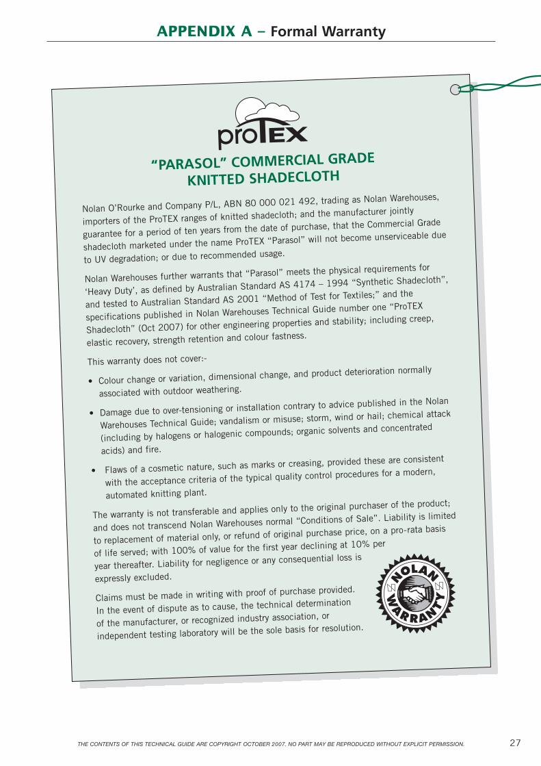
27THE CONTENTS OF THIS TECHNICAL GUIDE ARE COPYRIGHT OCTOBER 2007. NO PART MAY BE REPRODUCED WITHOUT EXPLICIT PERMISSION.
Nolan O’Rourke and Company P/L, ABN 80 000 021 492, trading as Nolan Warehouses,
importers of the ProTEX ranges of knitted shadecloth; and the manufacturer jointly
guarantee for a period of ten years from the date of purchase, that the Commercial Grade
shadecloth marketed under the name ProTEX “Parasol” will not become unserviceable due
to UV degradation; or due to recommended usage.
Nolan Warehouses further warrants that “Parasol” meets the physical requirements for
‘Heavy Duty’, as defined by Australian Standard AS 4174 – 1994 “Synthetic Shadecloth”,
and tested to Australian Standard AS 2001 “Method of Test for Textiles;” and the
specifications published in Nolan Warehouses Technical Guide number one “ProTEX
Shadecloth” (Oct 2007) for other engineering properties and stability; including creep,
elastic recovery, strength retention and colour fastness.
This warranty does not cover:-
• Colour change or variation, dimensional change, and product deterioration normally
associated with outdoor weathering.
• Damage due to over-tensioning or installation contrary to advice published in the Nolan
Warehouses Technical Guide; vandalism or misuse; storm, wind or hail; chemical attack
(including by halogens or halogenic compounds; organic solvents and concentrated
acids) and fire.
• Flaws of a cosmetic nature, such as marks or creasing, provided these are consistent
with the acceptance criteria of the typical quality control procedures for a modern,
automated knitting plant.
The warranty is not transferable and applies only to the original purchaser of the product;
and does not transcend Nolan Warehouses normal “Conditions of Sale”. Liability is limited
to replacement of material only, or refund of original purchase price, on a pro-rata basis
of life served; with 100% of value for the first year declining at 10% per
year thereafter. Liability for negligence or any consequential loss is
expressly excluded.
Claims must be made in writing with proof of purchase provided.
In the event of dispute as to cause, the technical determination
of the manufacturer, or recognized industry association, or
independent testing laboratory will be the sole basis for resolution.
APPENDIX A – Formal Warranty
“PARASOL” COMMERCIAL GRADE
KNITTED SHADECLOTH

28
APPENDIX B – Test Certificates

29

APPENDIX B (continued)
30

31THE CONTENTS OF THIS TECHNICAL GUIDE ARE COPYRIGHT OCTOBER 2007. NO PART MAY BE REPRODUCED WITHOUT EXPLICIT PERMISSION.
APPENDIX C
Test Results for “SUNGUARD” B138 Thread
SHADECLOTH
Thread Recommendation
As the primary use of Shadecloth material is for outdoor applications, the key factors for thread selection include (1) Overall Seam Strength, and (2) Ultraviolet Resistance.
Based on data provided to the industry by the leading supplier of sewing thread fibers, The Dupont Company continues to recommend continuous filament polyester thread as the Number 1 selection for outdoor uses when UV exposure exists. Dupont polyester fibers exhibit the highest degree of UV Resistance, demonstrating a gradual degradation of tensile strength.
Laboratory Test
Fabric Factors: Tear Resistance in Warp Direction – 134N (30.1 pounds)Tear Resistance in Weft Direction – 226N (50.6 pounds)
Breaking Force in Warp Direction – 699N (157.1 pounds)Breaking Force in Weft Direction – 1789N (400.7 pounds)
Thread Test: Two pieces of Shadecloth material were sewn together using a lockstitchapplication with “SUNGUARD” Size B138 polyester in both the needleand bobbin. The initial seam strength registered at 170 pounds. Throughaccelerated weatherometer testing, after approximately 5 years of UVexposure, the seam strength degrades to about 85 pounds or 50% of theinitial level. Continuing at the same rate of degradation, after a period of10 years, the seam strength would be at 42 pounds.
Conclusion: At 30.1 pounds, the Shadecloth material will tear in the warp direction.This would be the weakest link of all fabric factors. Therefore, use of“SUNGUARD” Size B138 Polyester provides adequate strength during the useful life of the Shadecloth material, registering 85 pounds after 5 years and 42 pounds after 10 years.
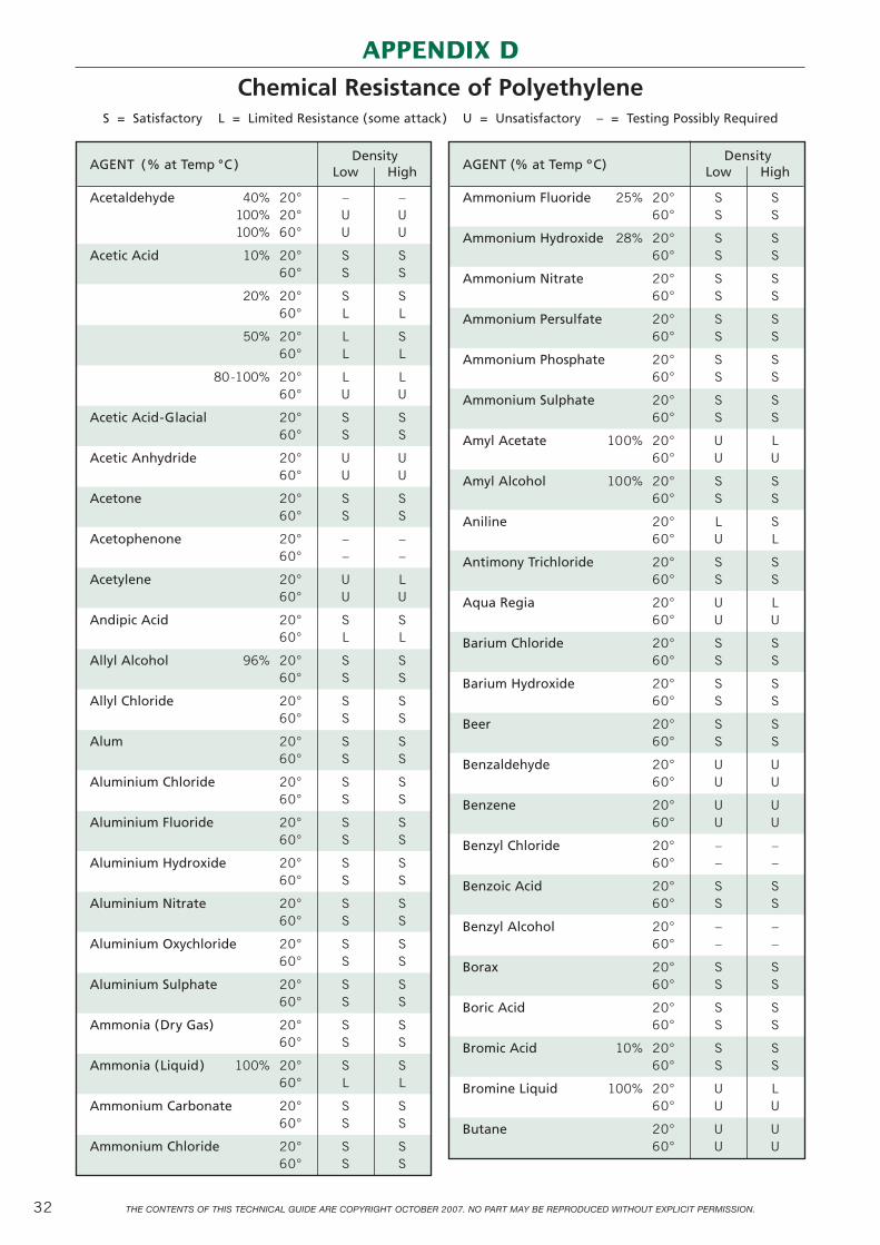
THE CONTENTS OF THIS TECHNICAL GUIDE ARE COPYRIGHT OCTOBER 2007. NO PART MAY BE REPRODUCED WITHOUT EXPLICIT PERMISSION.32
DensityAGENT (% at Temp °C ) Low High
Acetaldehyde 40% 20° – –100% 20° U U100% 60° U U
Acetic Acid 10% 20° S S60° S S
20% 20° S S60° L L
50% 20° L S60° L L
80-100% 20° L L60° U U
Acetic Acid-Glacial 20° S S60° S S
Acetic Anhydride 20° U U60° U U
Acetone 20° S S60° S S
Acetophenone 20° – –60° – –
Acetylene 20° U L60° U U
Andipic Acid 20° S S60° L L
Allyl Alcohol 96% 20° S S60° S S
Allyl Chloride 20° S S60° S S
Alum 20° S S60° S S
Aluminium Chloride 20° S S60° S S
Aluminium Fluoride 20° S S60° S S
Aluminium Hydroxide 20° S S60° S S
Aluminium Nitrate 20° S S60° S S
Aluminium Oxychloride 20° S S60° S S
Aluminium Sulphate 20° S S60° S S
Ammonia (Dry Gas) 20° S S60° S S
Ammonia (Liquid) 100% 20° S S60° L L
Ammonium Carbonate 20° S S60° S S
Ammonium Chloride 20° S S60° S S
APPENDIX D
Chemical Resistance of PolyethyleneS = Satisfactory L = Limited Resistance (some attack) U = Unsatisfactory – = Testing Possibly Required
AGENT (% at Temp ºC)Density
Low High
Ammonium Fluoride 25% 20° S S60° S S
Ammonium Hydroxide 28% 20° S S60° S S
Ammonium Nitrate 20° S S60° S S
Ammonium Persulfate 20° S S60° S S
Ammonium Phosphate 20° S S60° S S
Ammonium Sulphate 20° S S60° S S
Amyl Acetate 100% 20° U L60° U U
Amyl Alcohol 100% 20° S S60° S S
Aniline 20° L S60° U L
Antimony Trichloride 20° S S60° S S
Aqua Regia 20° U L60° U U
Barium Chloride 20° S S60° S S
Barium Hydroxide 20° S S60° S S
Beer 20° S S60° S S
Benzaldehyde 20° U U60° U U
Benzene 20° U U60° U U
Benzyl Chloride 20° – –60° – –
Benzoic Acid 20° S S60° S S
Benzyl Alcohol 20° – –60° – –
Borax 20° S S60° S S
Boric Acid 20° S S60° S S
Bromic Acid 10% 20° S S60° S S
Bromine Liquid 100% 20° U L60° U U
Butane 20° U U60° U U

THE CONTENTS OF THIS TECHNICAL GUIDE ARE COPYRIGHT OCTOBER 2007. NO PART MAY BE REPRODUCED WITHOUT EXPLICIT PERMISSION. 33
DensityAGENT (% at Temp °C ) Low High
Butyl Acetate 20° U L60° U U
Butyl Alcohol 20° S S60° S S
Butyric Acid 20% 20° U U60° U U
Calcium Chloride 20° S S60° S S
Calcium Hydroxide 20° S S60° S S
Calcium Nitrate 20° S S60° S S
Calcium Sulfate 20° S S60° S S
Carbon Bisulphide 20° U U60° U U
Carbon Disulphide 20° U U60° U U
Carbon Tetrachloride 20° U U60° U U
Carbonic Acid 20° S S60° S S
Castor Oil 20° S S60° S S
Chloral Hydrate 20° U U60° U U
Chlorine Gas 20° L L60° U U
Chlorine Liquid 20° U U60° U U
Chlorine Water 20% 20° L S60° U S
Chlorobenzene 20° U L60° U U
Chloroform 20° U L60° U U
Chlorosulfonic Acid 20° U U60° U U
Chromic Acid 10% 20° L S60° L S
Chromic Acid 50% 20° L S60° U S
Citric Acid 10% 20° S S60° S S
Copper Chloride 20° S S60° S S
Copper Sulphate 20° S S60° S S
Cresol 20° U U60° U U
* It should be noted that contact between Polypropylene and Copper or Copper Salts may result in a cracking of the Polypropylene.
DensityAGENT (% at Temp °C ) Low High
Crude Oil 20° U U60° U U
Cyclohexanol 20° L S60° L S
Cyclohexanone 20° U U60° U U
Dibutyl Phthalate 20° – –60° – –
Dioxane 20° U U60° U U
Ether 20° U U60° U U
Ethyl Acetate 20° L L60° U L
Ethyl Alcohol 30% 20° S S60° S S
Ethyl Alcohol 100% 20° S S60° S S
Ethyl Ether 20° U L60° U U
Ethylene Bromide 20° U U60° U U
Ethylene Dichloride 20° U U60° U U
Ethylene Glycol 20° S S60° S S
Ferric Chloride 20° S S60° S S
Ferrous Chloride 20° S S60° S S
Ferrous Sulphate 20° S S60° S S
Flourine Gas 20° U L60° U U
Formaldehyde 30% 20° S S60° L S
Formic Acid 10% 20° S S60° S S
Formic Acid 50% 20° S S60° S S
Freon 12 20° S S60° L S
Gas Natural 20° U L60° U U
Gasoline (Petrol) 20° U L60° S S
Glycerol (Glycerine) 20° S S60° S S
Glycol 20° S S60° S S

THE CONTENTS OF THIS TECHNICAL GUIDE ARE COPYRIGHT OCTOBER 2007. NO PART MAY BE REPRODUCED WITHOUT EXPLICIT PERMISSION.34
S = Satisfactory L = Limited Resistance (some attack) U = Unsatisfactory – = Testing Possibly Required
APPENDIX D (continued)
DensityAGENT (% at Temp °C ) Low High
Naphthalene 20° L S60° U U
Nickel Chloride 20° S S60° S S
Nickel Sulphate 20° S S60° S S
Nitric Acid 10% 20° S S60° S S
Nitric Acid CONC. 20° U U60° U U
Nitrobenzene 20° U U60° U U
Oleic Acid 20° S S60° S S
Olive Oil 20° S S60° L –
Oxalic Acid 10% 20° S S60° S S
Oxygen 20° S S60° S S
Ozone 20° U U60° U U
Perchloroethylene 20° – –60° – –
Petroleum Ether 100% 20° U U60° U U
Phenol 20° U –60° U –
Phosphoric Acid 10% 20° S S60° S S
Phosphoric Acid 75% 20° S S60° L S
Phosphorus, Yellow 20° L S60° L –
Phosphorus Pentoxide 20° L S60° L S
Phosphorus Trichloride 20° L –60° U –
Photographic Chemicals 20° S S60° S S
Plating Solutions Chromium 20° U S60° U S
Potassium Bicarbonate 20° S S60° S S
Potassium Carbonate 20° S S60° S S
Potassium Chloride 20° S S60° S S
Potassium Hydroxide 10% 20° S S60° S S
DensityAGENT (% at Temp °C ) Low High
Heptane 20° U L60° U U
Hexane 20° U U60° U U
Hydrochloric Acid 20% 20° S S60° S S80° – –
Hydrochloric Acid 40% 20° S S60° S S
Hydrocyanic Acid 20° S S60° S S
Hydrofluoric Acid 25% 20° S S60° L S
Hydrofluoric Acid 40% 20° S S60° L S
Hydrofluoric Acid Conc. 20° – S60° – –
Hydrogen Peroxide 30% 20° S S60° L S
Hydrogen Peroxide 90% 20° U S60° U L
Iodine ( In Alcohol) 20° U U60° U U
Isopropyl Alcohol 20° S S60° S S
Kerosene 20° U L60° U U
Lubricating Oils 20° U L60° U L
Magnesium Chloride 20° S S60° S S
Magnesium Sulphate 20° S S60° S S
Mercuric Chloride 20° S S60° S S
Mercury 20° S S60° S S
Methyl Alcohol 100% 20° S S60° S S
Methyl Ethyl Ketone 20° U U60° U U
Methyl Salicylate 20° – –
Methyl Sulphate 20° U U60° – –
Methylene Chloride 20° U U60° U U
Mineral Oils 20° L S60° U U
Naphtha 20° U L60° U L
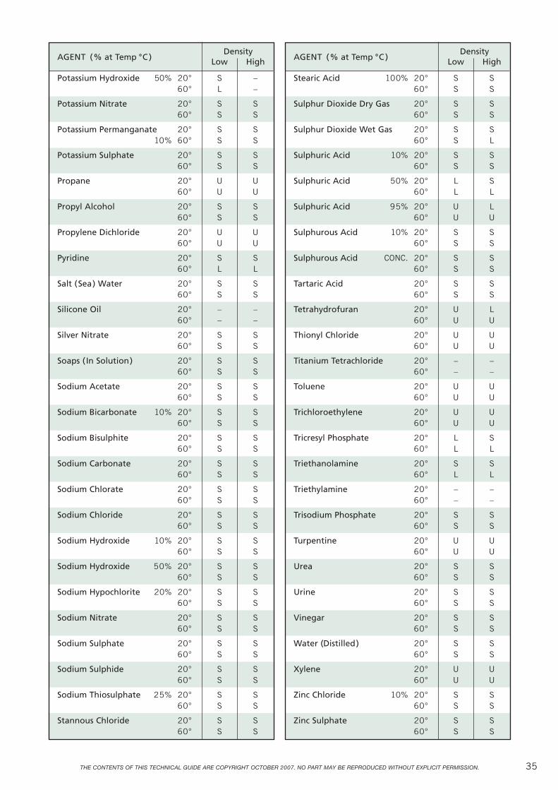
THE CONTENTS OF THIS TECHNICAL GUIDE ARE COPYRIGHT OCTOBER 2007. NO PART MAY BE REPRODUCED WITHOUT EXPLICIT PERMISSION. 35
DensityAGENT (% at Temp °C ) Low High
Stearic Acid 100% 20° S S60° S S
Sulphur Dioxide Dry Gas 20° S S60° S S
Sulphur Dioxide Wet Gas 20° S S60° S L
Sulphuric Acid 10% 20° S S60° S S
Sulphuric Acid 50% 20° L S60° L L
Sulphuric Acid 95% 20° U L60° U U
Sulphurous Acid 10% 20° S S60° S S
Sulphurous Acid CONC. 20° S S60° S S
Tartaric Acid 20° S S60° S S
Tetrahydrofuran 20° U L60° U U
Thionyl Chloride 20° U U60° U U
Titanium Tetrachloride 20° – –60° – –
Toluene 20° U U60° U U
Trichloroethylene 20° U U60° U U
Tricresyl Phosphate 20° L S60° L L
Triethanolamine 20° S S60° L L
Triethylamine 20° – –60° – –
Trisodium Phosphate 20° S S60° S S
Turpentine 20° U U60° U U
Urea 20° S S60° S S
Urine 20° S S60° S S
Vinegar 20° S S60° S S
Water (Distilled) 20° S S60° S S
Xylene 20° U U60° U U
Zinc Chloride 10% 20° S S60° S S
Zinc Sulphate 20° S S60° S S
DensityAGENT (% at Temp °C ) Low High
Potassium Hydroxide 50% 20° S –60° L –
Potassium Nitrate 20° S S60° S S
Potassium Permanganate 20° S S10% 60° S S
Potassium Sulphate 20° S S60° S S
Propane 20° U U60° U U
Propyl Alcohol 20° S S60° S S
Propylene Dichloride 20° U U60° U U
Pyridine 20° S S60° L L
Salt (Sea) Water 20° S S60° S S
Silicone Oil 20° – –60° – –
Silver Nitrate 20° S S60° S S
Soaps ( In Solution) 20° S S60° S S
Sodium Acetate 20° S S60° S S
Sodium Bicarbonate 10% 20° S S60° S S
Sodium Bisulphite 20° S S60° S S
Sodium Carbonate 20° S S60° S S
Sodium Chlorate 20° S S60° S S
Sodium Chloride 20° S S60° S S
Sodium Hydroxide 10% 20° S S60° S S
Sodium Hydroxide 50% 20° S S60° S S
Sodium Hypochlorite 20% 20° S S60° S S
Sodium Nitrate 20° S S60° S S
Sodium Sulphate 20° S S60° S S
Sodium Sulphide 20° S S60° S S
Sodium Thiosulphate 25% 20° S S60° S S
Stannous Chloride 20° S S60° S S

36 THE CONTENTS OF THIS TECHNICAL GUIDE ARE COPYRIGHT OCTOBER 2007. NO PART MAY BE REPRODUCED WITHOUT EXPLICIT PERMISSION.
L1
d1
L2
d2
T
T T
w
RR
R
2 1
R
Hoop Stress T = R x w
Where T = Cable Tension (kN)
R = Circle Radius (m)
w = Applied Stress (kN/m)
Therefore Radius: Equation No. (1)R = Tw
APPENDIX E
Relationship Between Cable Tension and Curvature
For design conditions of uniform reactive stress, and constant cable tension, the radius of curvature is the same for each span.

L
d
w
A
C B
8.56
6
Sag orDepth:
d
Chord: L
Radius: R
37THE CONTENTS OF THIS TECHNICAL GUIDE ARE COPYRIGHT OCTOBER 2007. NO PART MAY BE REPRODUCED WITHOUT EXPLICIT PERMISSION.
A
For constant cable tension and reactivestress, d = kL2 where k is constant.
This equation is approximate and should only be used for initial design.
(L n)2
L1
A
d
wL 2
L 4
T
... d = wL2
8TT.d = wL . L
2 4
...dn =d1
For preliminary design purposes, a simpler relationship between depth and span can be derived as follows:–
Take moments about A
d = ( ) – 4 ( ) – 8.5
2
2 2
AB
d = d = 0.25 AC CB
4.60.25
4.60.25 = 0.50
Example:How to use theory to determine a depth of cut that results in a uniformly stressed sail.
• Allowable stress: = 0.25kN/m
• Cable Tension: = 4.6kN
Therefore Depth:
Equation No. (2)
Sag:
Substitute (1) into (2) Then:
d = –4 ( ) – L
2
2 2
Tw
Tw
d = R –4R – L
2
2 2

38 THE CONTENTS OF THIS TECHNICAL GUIDE ARE COPYRIGHT OCTOBER 2007. NO PART MAY BE REPRODUCED WITHOUT EXPLICIT PERMISSION.
L2
L
D
L1
B
D
L
A
C B
H D
L
DE
C AB
Size (mm)
D L1 L2 L B B/S
10 100 145 90 21 2250Kg
12 120 170 107 25 3240Kg
EYE BOLTS – Supplied with 2 stainless steel washers and 1 stainless steel hex nut.
SNAP HOOK WITH EYE
EYE BOLTS – Collared(with steel washer and hex nut)
DEE RINGS – Strong 316 gradestainless steel. Argonwelded non-corrosive.
EYE NUTS – (with a female metric thead)
(Grade 316 Stainless Steel)
Size (mm)
D A B C E B/S
10 100 88 8 24 2500Kg
12 120 105 10 30 3600Kg
Size (mm)
D L A B C S.W.L.
10 45 41 24 8 150Kg
12 57 50 30 10 220Kg
Size (mm)
L D B E B/S
50 6 7 7 450Kg
Size (mm)
D L B B/S
6 21 12 1800KG
8 28 16 3500KG
10 35 20 5400KG
12 42 24 7200KG
Size (mm)
D L H
5 25 22
6 40 35
6 50 43
EB
L
D
D
BL
SHACKLES – (with Pin)
B/S – Breaking Strength S.W.L. – Safe Weight Limit
APPENDIX F
Shadesail Fittings

39
D
L2
A
L1
B
Product Size (mm)
D A B L1 L2 L2 B/Smin max
EYE & HOOK 8 11 14 120 200 290 2500Kg
10 12 16 150 245 350 3900Kg
12 14 19 200 325 470 6400Kg
HOOK & HOOK 8 11 120 200 290 2500Kg
10 12 150 245 350 3900Kg
12 14 200 325 470 6400Kg
EYE & EYE 8 14 120 200 290 2500Kg
10 16 150 245 350 3900Kg
12 19 200 325 470 6400Kg
THE CONTENTS OF THIS TECHNICAL GUIDE ARE COPYRIGHT OCTOBER 2007. NO PART MAY BE REPRODUCED WITHOUT EXPLICIT PERMISSION.
“SELF-PIERCING EYELETS”Available in brass or nickel. Machine dyes and handpunches available to suit each size shown. (Refer theNolan Catalogue – Volume 3).
External Internal BarrelSize Diameter (D) Diameter (d) Length (b)
SP00 6.7mm 3.6mm 6.4mm
SP0 9.5mm 4.6mm 5.2mm
SP1 12.7mm 6.8mm 4.8mm
SP3* 19.1mm 7.9mm 5.6mm*
SP4* 20.6mm 9.5mm 5.6mm*
SP6* 22.2mm 11.1mm 5.6mm*
SP7* 27.0mm 12.7mm 7.1mm*
SP9* 31.8mm 15.9mm 7.9mm*
D d
b
EYE & HOOK TURNBUCKLE
HOOK & HOOK TURNBUCKLE EYE & EYE TURNBUCKLE
*Optional Spur tooth washer available forsizes SP3 - SP9

40 THE CONTENTS OF THIS TECHNICAL GUIDE ARE COPYRIGHT OCTOBER 2007. NO PART MAY BE REPRODUCED WITHOUT EXPLICIT PERMISSION.
NOTES
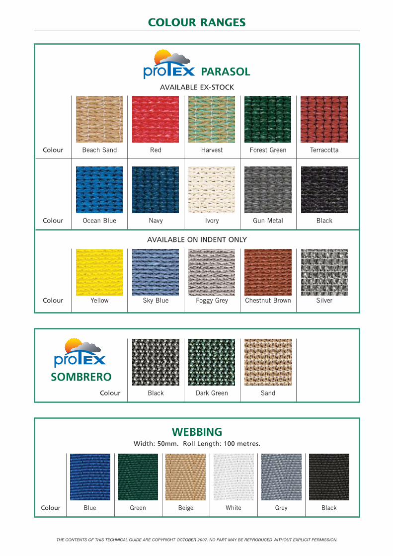
THE CONTENTS OF THIS TECHNICAL GUIDE ARE COPYRIGHT OCTOBER 2007. NO PART MAY BE REPRODUCED WITHOUT EXPLICIT PERMISSION.
COLOUR RANGES
PARASOLAVAILABLE EX-STOCK
Colour Beach Sand Red Harvest Forest Green Terracotta
Colour Ocean Blue Navy Ivory Gun Metal Black
AVAILABLE ON INDENT ONLY
Colour Yellow Sky Blue Foggy Grey Chestnut Brown Silver
SOMBREROColour Black Dark Green Sand
WEBBINGWidth: 50mm. Roll Length: 100 metres.
Colour Blue Green Beige White Grey Black

SYDNEY3 Bradford Street, Alexandria
P.O. Box 246, Rosebery, NSW 1445, AustraliaTelephone: (02) 9669 3333
Fax: (02) 9669 3266
NEWCASTLE66 Orlando Road, Lambton
Telephone: (02) 4957 7766Fax: (02) 4952 6737
BRISBANE11 Barrinia Street, SpringwoodTelephone: (07) 3808 1888
Fax: (07) 3208 0868
MELBOURNE55 Cleeland Road, Oakleigh South
Telephone: (03) 9545 5588Fax: (03) 9545 5582
ADELAIDE4 Paget Street, Ridleyton
Telephone: (08) 8340 7979Fax: (08) 8340 7877
PERTH168 Edward Street, Perth
Telephone: (08) 9328 4777Fax: (08) 9328 4719
www.nolans.com.au
Nolan WarehousesESTABLISHED 1920


DR 420/2017 - The Trust Company (Australia) v Metro north-west JDAP (Dog Swamp Shopping Centre Extension)
Refusal Reasons
1. The proposed development is contrary to the objectives and development provisions
of Local Planning Policy 6.6 (Landscaping) as the proposal seeks to remove existing
vegetation in the southern car park area and as a result will not meet the City's
minimum requirement of 1 tree per 6 car parking bays.
2. The proposed development is contrary to Clause 5.13 of the City's Local Planning
Scheme No. 3 in relation to Trees and Development and the objectives of Local
Planning Policy 6.11 (Trees and Development), which aims to minimise the removal
of significant trees on zoned land as a consequence of development.
3. The proposed development will have a negative impact on the visual amenity and
landscape character of the area due to the removal of trees and is thereby not in
accordance with Clause 67 of the Planning and Development (Local Planning
Schemes) Regulations 2015 in relation to preservation of the amenity of the locality.
Applicant Grounds for Review
The Application sought approval from the Metro North-West JDAP to amend the existing DAP approval to permit new shade structures over the southern car parking area for the purposes of providing adequate shade and weather protection to visitors and pedestrians to the centre. Local Planning Policy No. 4.2: Mixed Use and Commercial Centre Design Guidelines states; Design and Location of Car Parking Spaces The relevant requirements for the design and location of car parking spaces are as follows:
Parking bays shall be designed in accordance with the relevant Australian Standard and shall have /tree per 6 parking bays, as required by the City's Landscaping Policy.
The proposed development will require the removal of up to 11 trees. The removal of the trees is discussed in detail pursuant to LPP 4.2 and in accordance with the landscaping requirements of LPP 6.6 below. Colours and Materials LPP 4.2 stipulates the following requirements for development within the District Centre with regard to colours and materials:
New colour schemes shall take into consideration the colour scheme of existing buildings and shall not be in sharp contrast;
Fluorescent and intense colours shall not be used; and
In traditional shopping areas materials and colours sympathetic with existing buildings shall be used.

DR 420/2017 - The Trust Company (Australia) v Metro north-west JDAP (Dog Swamp Shopping Centre Extension)
As noted, the proposed shade structures are to be in the colour Charcoal" and “Light Grey which is considered to complement the existing buildings on site, and is not considered to be of a fluorescent or intense colour palette. As such, either Option 1 or Option 2 are considered appropriate and address the requirements above, noting that the colours and materials of the proposed shade structures are typical to the colours and materials of shade structures throughout shopping areas in the Perth metropolitan area. Local Planning Policy No 6.6: Landscaping states; Retention of Existing Vegetation LPP 6.6 stipulates that the City encourages the retention of existing vegetation and wilt consider the exercise of discretion in its application of scheme requirements and adopted local policies where such a variation would allow for the retention of significant existing vegetation on a site. The applicant seeks the discretion for the removal of up to 11 trees, on the following basis:
removal is required to accommodate the shade structures;
Existing trees are not considered to provide adequate shade and shelter in the
southern car park, nor do the trees have any significant heritage value;
Retention of the trees will lead to maintenance costs and cause damage to the
proposed shade structures;
the trees are not located in any setback area and do not currently provide any
screening from the streetscape;
Original DAP approval includes 15 new trees which are to be located in an area that
is considered to provide more adequate shelter and shade along the pedestrian link,
and allows for more softening at the edges.
The size and location of the trees to be removed are not considered to soften the car
parking areas to the south, as opposed to the location of the 15 new trees under the
DAP approval.
Having regard to the above, the removal of the aforementioned trees is considered to be an acceptable and a necessary response in order to accommodate the proposed shade structures. Orderly and Proper Planning The proposed development is demonstrated to be orderly and proper, with reference to IPS 3, State and local planning policies. The key aspects of the proposal to be taken into consideration are that:
The shade sails are considered to be incidental to the nature of the existing car parking area;
The shade sails are to be setback of approximately 13 metres, in excess of the existing building setbacks on site;
The shade sails comprise an open frame structure which will not result in any adverse impact with regard to bulk and scale or overshadowing;
There is a growing expectation from customers for shopping centres to provide adequate shade and shelter which has been identified through customer experience surveys;

DR 420/2017 - The Trust Company (Australia) v Metro north-west JDAP (Dog Swamp Shopping Centre Extension)
The proposed colours and materials of the shade structure are compatible with the existing buildings on site;
The retention of the aforementioned trees and integration of any shade structures will result in ongoing maintenance issues and operational costs, and cause damage to the shade structures;
Those trees to be removed are not considered to currently provide adequate shade and protection to visitors, nor do they provide any screening from the public realm;
15 new trees are to be planted as part of the original planning approval which are of a plant species which is generally considered to provide more effective shade and canopy cover as opposed to those trees to be removed;
No new car parking spaces were created as part of the approved scope of works;
The proposed development in anticipated to improve the comfort and convenience of the site for visitors and pedestrians; and
There are existing shopping centres throughout the Perth metropolitan area which have set the precedence for shade sails on sites of a similar nature. This is evident on a number to shopping centres including Mandurah Greenfields Shopping Centre, Aveley Shopping Centre and Seacrest Shopping Centre, as demonstrated in Attachment D - Example Shade Structure Photographs.