metric hydraulic cylinders - parker cylinder...
TRANSCRIPT

Metric Hydraulic CylindersSeries HMI

Metric Hydraulic CylindersSeries HMI
www.parker.com/cylinder
Catalog HY08-1151-2/NA
Parker Hannifin CorporationCylinder DivisionDes Plaines, Illinois USA
Parker Series HMI Metric Hydraulic Cylinders
In line with our policy of continuing product improvement, specifications and information contained in this catalog are subject to change.Copyright ©2017 by Parker Hannifin Corporation. All rights reserved.PRINTED IN THE U.S.A.
WARNINGFAILURE OR IMPROPER SELECTION OR IMPROPER USE OF THE PRODUCTS AND/OR SYSTEMS DESCRIBED HEREIN OR RELATED ITEMS CAN CAUSE DEATH, PERSONAL INJURY AND PROPERTY DAMAGE.This document and other information from the Parker Hannifin Corporation, its subsidiaries and authorized distributors provide product and/or system options for further investigation by users having expertise. It is important that you analyze all aspects of your application, including consequences of any failure and review the information concerning the product or system in the current product catalog. Due to the variety of operating conditions and applications for these products or systems, the user, through its own analysis and testing, is solely responsible for making the final selection of the products and systems and assuring that all performance, safety and warning requirements of the application are met.
The products described herein, including without limitation, product features, specifications, designs, availability and pricing, are subject to change by Parker Hannifin Corporation and its subsidiaries at any time without notice.
Offer of SaleThe items described in this document are hereby offered for sale by Parker Hannifin Corporation, its subsidiaries or its authorized distributors. This offer and its acceptance are governed by provisions stated on a separate page of the document entitled ‘Offer of Sale’.
As the world leader in the design and manufacture of tie-rod cylinders, Parker Cylinder Division introduces the Parker Series HMI metric hydraulic cylinder. Parker’s HMI Series cylinders are designed to meet the requirements of ISO 6020/2 (1991), 160 Bar Compact Series. HMI Series cylinders may be used for working pressures up to 210 Bar.
Parker HMI Series cylinders are the true world standard, available all over the globe from Parker’s worldwide manufacturing facilities. Whether you or your machine are in Europe, Asia, South America, Canada, Mexico, or the United States, you can rely on the engineering expertise, manufacturing experience, and commitment to quality that you’ve come to expect from the Parker Cylinder Division.

Metric Hydraulic CylindersSeries HMI
1www.parker.com/cylinder
Catalog HY08-1151-2/NA
Parker Hannifin CorporationCylinder DivisionDes Plaines, Illinois USA
Series HMI Standard Features and Specifications• ISO 6020/2 mounting interchangeable• 12 standard mounting styles• Up to 3 rod sizes per bore• Wide range of mounting accessories• Up to 3 male and 3 female rod end threads per bore• Bore sizes – 25mm to 200mm• Strokes – available in any practical stroke length
• Working pressure up to 210 bar• Piston rods – 12mm to 140mm• Single and Double rod designs• Cushions available at either end• Temperature Range – -20°C to 150°C
depending on seal type• Seal types to suit a wide variety of operating environments
ISO MX1
Page 6
Page 7
ISO MP5
Page 8
ISO MT4
Page 9
Available Mountings and Where To Find Them
ISO MX3
TB Page 6
ISO ME5
JJ Page 7
ISO MP3
B
ISO MT1
D Page 9
ISO MX2
TC Page 6
ISO ME6
HH Page 7
ISO MP1
BB Page 8
ISO MT2
DB Page 9
TD
C
SB
DD
Page 8
In line with our policy of continuing product improvement, specifications in this catalog are subject to change.
ISO MS2
Features, Specifications and Mountings
Theoretical Push and Pull Forces . . . . . . . . . . . . . . . . . . . . . 20 Piston Rod Sizes & Stop Tubes . . . . . . . . . . . . . . . . . . . . . . 21 Stroke Factors . . . . . . . . . . . . . . . . . . . . . . . . . . . . . . . . . . . . 22 Cushioning . . . . . . . . . . . . . . . . . . . . . . . . . . . . . . . . . . . 23-25 Pressure Limitations . . . . . . . . . . . . . . . . . . . . . . . . . . . . . . . 25 Ports, Locations and Piston Speeds . . . . . . . . . . . . . . . . . . 26 Ports / Weights . . . . . . . . . . . . . . . . . . . . . . . . . . . . . . . . . . . 27 Seals and Fluids . . . . . . . . . . . . . . . . . . . . . . . . . . . . . . . . . . 28 Optional Features . . . . . . . . . . . . . . . . . . . . . . . . . . . . . . 28-29 Cylinder Safety Guide . . . . . . . . . . . . . . . . . . . . . . . . . . . 30-31 Offer of Sale . . . . . . . . . . . . . . . . . . . . . . . . . . . . . . . . . . . . . 32
Table of ContentsFeatures, Specifications and Mountings . . . . . . . . . . . . . . . . 1 Design Features and Benefits . . . . . . . . . . . . . . . . . . . . . . 2-3 Mounting Styles and Applications . . . . . . . . . . . . . . . . . . . . . 4 Piston Rod End Data and Threads . . . . . . . . . . . . . . . . . . . . . 5 Dimensional Data . . . . . . . . . . . . . . . . . . . . . . . . . . . . . . . . 6-9 Double Rod Cylinders . . . . . . . . . . . . . . . . . . . . . . . . . . . . . . 10 Accessories . . . . . . . . . . . . . . . . . . . . . . . . . . . . . . . . . . . .11-13 Model Numbers . . . . . . . . . . . . . . . . . . . . . . . . . . . . . . . . .14-15 Parts Identification . . . . . . . . . . . . . . . . . . . . . . . . . . . . . . . . 16 Seal Kits and Replacement Parts . . . . . . . . . . . . . . . . . . . . . 17 Mounting Information . . . . . . . . . . . . . . . . . . . . . . . . . . . 18-19
Metric Hydraulic CylindersSeries HMI
2www.parker.com/cylinder
Catalog HY08-1151-2/NA
Parker Hannifin CorporationCylinder DivisionDes Plaines, Illinois USA
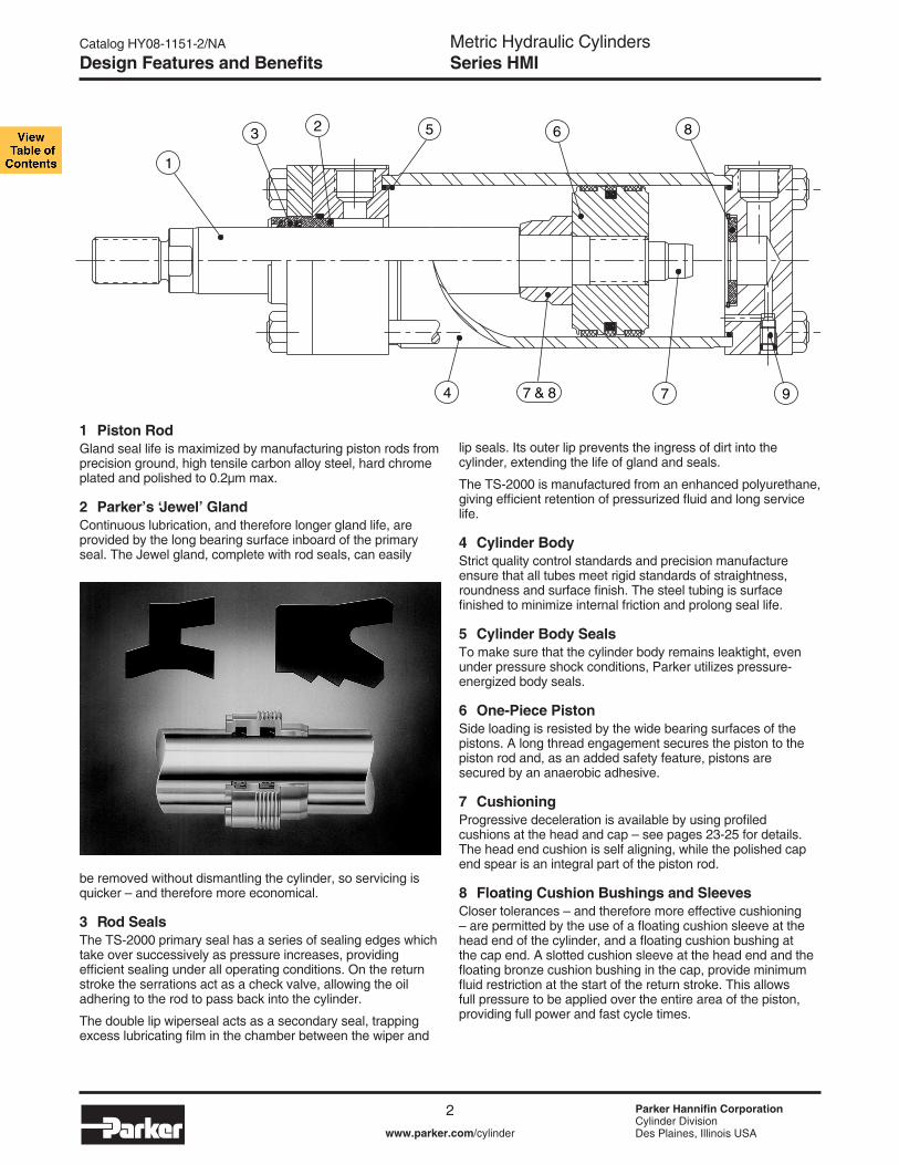
1 Piston RodGland seal life is maximized by manufacturing piston rods from precision ground, high tensile carbon alloy steel, hard chrome plated and polished to 0.2µm max.
2 Parker’s ‘Jewel’ GlandContinuous lubrication, and therefore longer gland life, are provided by the long bearing surface inboard of the primary seal. The Jewel gland, complete with rod seals, can easily
be removed without dismantling the cylinder, so servicing is quicker – and therefore more economical.
3 Rod SealsThe TS-2000 primary seal has a series of sealing edges which take over successively as pressure increases, pro vid ing efficient sealing under all operating conditions. On the return stroke the serrations act as a check valve, allow ing the oil adhering to the rod to pass back into the cylinder.
The double lip wiperseal acts as a secondary seal, trapping excess lubricating film in the chamber between the wiper and
1
3
4
2 5 6 8
977 & 8
lip seals. Its outer lip prevents the ingress of dirt into the cylinder, extending the life of gland and seals.
The TS-2000 is manufactured from an enhanced poly urethane, giving efficient retention of pressurized fluid and long service life.
4 Cylinder BodyStrict quality control standards and precision manufacture ensure that all tubes meet rigid standards of straightness, roundness and surface finish. The steel tubing is surface finished to minimize internal friction and prolong seal life.
5 Cylinder Body SealsTo make sure that the cylinder body remains leaktight, even under pressure shock conditions, Parker utilizes pressure- energized body seals.
6 One-Piece PistonSide loading is resisted by the wide bearing surfaces of the pistons. A long thread engagement secures the piston to the piston rod and, as an added safety feature, pistons are secured by an anaerobic adhesive.
7 CushioningProgressive deceleration is available by using profiled cushions at the head and cap – see pages 23-25 for details. The head end cushion is self aligning, while the polished cap end spear is an integral part of the piston rod.
8 Floating Cushion Bushings and SleevesCloser tolerances – and therefore more effective cushioning – are permitted by the use of a floating cushion sleeve at the head end of the cylinder, and a floating cushion bushing at the cap end. A slotted cushion sleeve at the head end and the floating bronze cushion bushing in the cap, provide minimum fluid restriction at the start of the return stroke. This allows full pressure to be applied over the entire area of the piston, providing full power and fast cycle times.
Design Features and Benefits

Metric Hydraulic CylindersSeries HMI
3www.parker.com/cylinder
Catalog HY08-1151-2/NA
Parker Hannifin CorporationCylinder DivisionDes Plaines, Illinois USA
9 Cushion AdjustmentNeedle valves are provided at both ends of the cylinder for precise cushion adjustment. 63 mm bores and smaller contain cartridge cushion assembly shown below.
Gland DrainsThe accumulation of fluid behind the gland wiperseal of long stroke cylinders, or cylinders with constant back pressure, can be relieved by specifying the option of a gland drain. A port between the wiperseal and primary seal allows fluid to be piped back to a reservoir. By fitting a transparent tube between the port and the reservoir, fluid loss from concealed or inaccessible cylinders can be monitored to provide an early indication of the need for gland servicing. Gland drains are described in greater detail on page 29.
Air BleedsAvailable as an option at both ends, the air bleeds are recessed into the head and cap.
Standard on 50mm bore sizes and larger, Parker’s B style piston is a single seal design which incorporates two wear strips. This design provides smooth operation, long bearing life, and high load carrying capacity.
Mixed Media Piston SealsFor applications requiring different media on either side of the piston specify Mixed Media Piston Seals with a W piston code. This option is ideal when hydraulic oil is on one side of the piston and air on the opposite side; and it can be equally effective when dissimilar fluids are on either side of the piston. Superior low-friction bi-directional sealing is accomplished by combining an energized filled PTFE seal with a redundant elastomer seal.
Servo CylindersServo cylinders permit fine control of acceleration, velocity and position in applications where very low friction and an absence of stick-slip are required. They may be used in conjunction with integral or external transducers. Servo cylinders combine low friction piston and gland seals with specially selected tubes and rods. For low-friction appli cations – consult factory.
Seal ClassesTo accommodate the many types of fluids and the varying temperature ranges used in industry, Parker offers a range of rod gland, piston and body seals. These are described in detail on page 28.
Piston Seals Standard on 25mm, 32mm and 40mm bore sizes, Parker’s Lipseal™ Piston provides zero leakage under static conditions for hydraulic pressures up to 3000 psi. Seals are self-compensating to conform to variations in pressure, mechanical deflection, and wear. Back-up washers prevent extrusion.
Design Features and Benefits

Metric Hydraulic CylindersSeries HMI
4www.parker.com/cylinder
Catalog HY08-1151-2/NA
Parker Hannifin CorporationCylinder DivisionDes Plaines, Illinois USA
ISO Cylinder Mounting Styles The standard range of Parker Series HMI cylinders comprises 12 ISO mounting styles, to suit the majority of applications. General guidance for the selection of ISO cylinders is given below, with dimensional information about each mounting style shown on the following pages. Application-specific mounting information is shown in the mounting information section on page 18.
Extended Tie Rods Cylinders with TB, TC and TD mountings are suitable for straight line force transfer applications, and are particularly useful where space is limited. For compression (push) applications, cap end tie rod mountings are most appropriate; where the major load places the piston rod in tension (pull applications), head end mounting styles should be specified. Cylinders with tie rods extended at both ends may be attached to the machine member from either end, allowing the free end of the cylinder to support a bracket or switch.
Flange Mounted Cylinders These cylinders are also suitable for use on straight line force transfer applications. Two flange mounting styles are available, offering either a head flange (JJ) or a cap flange (HH). Selection of the correct flange mounting style depends on whether the major force applied to the load will result in compression (push) or tension (pull) stresses on the piston rod. For compression-type applications, the cap mounting style is most appropriate; where the major load places the piston rod in tension, a head mounting should be specified.
Foot Mounted Cylinders Style C, foot mounted cylinders do not absorb forces on their centerline. As a result, the application of force by the cylinder produces a moment which attempts to rotate the cylinder about its mounting bolts. It is important, therefore, that the cylinder should be firmly secured to the mounting surface and that the load should be effectively guided to avoid side loads being applied to rod gland and piston bearings. A thrust key modification may be specified to provide positive cylinder location.
Pivot Mountings Cylinders with pivot mountings, which absorb forces on their centerlines, should be used where the machine member to be moved travels in a curved path. Pivot mountings may be used for tension (pull) or compression (push) applications. Cylinders using a fixed clevis, styles BB and B, may be used if the curved path of the piston rod travel is in a single plane; for applications where the piston rod will travel in a path on either side of the true plane of motion, a spherical bearing mounting SB is recommended.
Trunnion Mounted Cylinders These cylinders, styles D, DB and DD, are designed to absorb force on their centerlines. They are suitable for tension (pull) or compression (push) applications, and may be used where the machine member to be moved travels in a curved path in a single plane. Trunnion pins are designed for shear loads only and should be subjected to minimum bending stresses.
Styles TB, TC, TD ISO Styles MX3, MX2, MX1 TB
Styles JJ, HH ISO Styles ME5, ME6 HH
Style C ISO Style MS2 C
Styles B, BB, SB ISO Styles MP3, MP1, MP5 BB
Styles D, DB, DD ISO Styles MT1, MT2, MT4 DB
Mounting Styles and Applications

Metric Hydraulic CylindersSeries HMI
5www.parker.com/cylinder
Catalog HY08-1151-2/NA
Parker Hannifin CorporationCylinder DivisionDes Plaines, Illinois USA
All dimensions are in millimeters unless otherwise stated.1 Use WD dimension for mounting Style D in 100mm - 200mm bore. See Style D page for details.
MM Style 4 Style 7 Style 9 B D NA VE WF JJ Mount Only Bore Rod Rod f9 VL RD VJ FJ o No. o KK A KK A KF A min f8
25
1 12 M10x1.25 14 - - M8x1 14 24 10 11 16 25
3 38 6 10
2 18 M14x1.5 18 M10x1.25 14 M12x1.25 18 30 15 17 16
32 1 14 M12x1.25 16 - - M10x1.25 16 26 12 13 22
35
3 42 12 10 2 22 M16x1.5 22 M12x1.25 16 M16x1.5 22 34 19 21 22
40 1 18 M14x1.5 18 - - M12x1.25 18 30 15 17 16
35
3 62 6
10 2 28 M20x1.5 28 M14x1.5 18 M20x1.5 28 42 22 26 22 12 1 22 M16x1.5 22 - - M16x1.5 22 34 19 21 22 6 50 2 36 M27x2 36 M16x1.5 22 M27x2 36 50 30 34 25 41 4 74 9 16 3 28 M20x1.5 28 M16x1.5 22 M20x1.5 28 42 22 26 22 6 1 28 M20x1.5 28 - - M20x1.5 28 42 22 26 22 75 6 63 2 45 M33x2 45 M20x1.5 28 M33x2 45 60 41 43 29 48 4
88 13 16
3 36 M27x2 36 M20x1.5 28 M27x2 36 50 30 34 25 9 1 36 M27x2 36 - - M27x2 36 50 30 34 25 82 5 80 2 56 M42x2 56 M27x2 36 M42x2 56 72 50 54 29 51 4
105 9 20
3 45 M33x2 45 M27x2 36 M33x2 45 60 41 43 29 1 45 M33x2 45 - - M33x2 45 60 41 43 29 92 7 100 2 70 M48x2 63 M33x2 45 M48x2 63 88 60 68 32 571 5
125 10 22
3 56 M42x2 56 M33x2 45 M42x2 56 72 50 54 29 7 1 56 M42x2 56 - - M42x2 56 72 50 54 29 105 9 20 125 2 90 M64x3 85 M42x2 56 M64x3 85 108 80 88 32 571 5
150 10 22 3 70 M48x2 63 M42x2 56 M48x2 63 88 60 68 32 1 70 M48x2 63 - - M48x2 63 88 60 68 32 125 10 22 160 2 110 M80x3 95 M48x2 63 M80x3 95 133 100 108 32 571 5
170 7 25 3 90 M64x3 85 M48x2 63 M64x3 85 108 80 88 32 1 90 M64x3 85 - - M64x3 85 108 80 88 32 150 10 22 200 2 140 M100x3 112 M64x3 85 M100x3 112 163 128 138 32 571 5
210 7 25 3 110 M80x3 95 M64x3 85 M80x3 95 133 100 108 32
Parker Thread Style 9 – Short Stroke CylindersStyle 9 (female) rod ends should not be used on 160mm or 200mm bore cylinders with a stroke of 50mm or less. Please consult the factory, with details of the application.
Parker Thread Style 3Non-standard piston rod ends are designated ‘Style 3’. A dimensional sketch or description should accompany the order. Please specify dimensions KK or KF, A, rod stand out WF and thread type.
Gland Retainer – 160 and 200mm BoreOn all 160mm and 200mm bore ISO mounting styles except TB and TD, the gland retainer is separately bolted to the head, as shown.
Parker Thread Styles 4 & 7The smallest diameter rod end thread for each bore size is designated Style 4 when supplied with a No.1 rod. When the same rod end thread is supplied with a No. 2 or No. 3 rod, it is designated Style 7.
25 & 32mm Bore Cylinders
5mm extra height applies to port face at head end only.
Parker Thread Styles 4 & 7 – All Except JJ Mount
Parker Thread Style 9 – All Except JJ Mount
Parker Thread Styles 4 & 7 – JJ Mount
Parker Thread Style 9 – JJ Mount
Piston Rod End Dimensions
WF
A
B
DWrench Flats
NA KK MM
VE
B
A
RD NA KK
VE
VJ
VLFJ
WF
MM
DWrench Flats
WF
A
B
DWrench Flats
NA KF MM
VEVE
VJ
VLFJ
WF
MMNABRD KF
T DWrench Flats
A
E
5mm
5mm
E
Piston Rod End Data and Threads

Metric Hydraulic CylindersSeries HMI
6www.parker.com/cylinder
Catalog HY08-1151-2/NA
Parker Hannifin CorporationCylinder DivisionDes Plaines, Illinois USA
AA BB DD E EE F FT G J KB TG WF WH Y + Stroke BSP/G inches PJ ZJ
40 19 M5x0.8 401 1/4 10 10 40 25 4 28.3 25 15 50 53 114 47 24 M6x1 451 1/4 10 10 40 25 5 33.2 35 25 60 56 128 59 35 M8x1 63 3/8 10 10 45 38 6.5 41.7 35 25 62 73 153 74 46 M12x1.25 75 1/2 16 16 45 38 10 52.3 41 25 67 74 159 91 46 M12x1.25 90 1/2 16 16 45 38 10 64.3 48 32 71 80 168 117 59 M16x1.5 115 3/4 20 20 50 45 13 82.7 51 31 77 93 190 137 59 M16x1.5 130 3/4 22 22 50 45 13 96.9 57 35 82 101 203 178 81 M22x1.5 165 1 22 22 58 58 18 125.9 57 35 86 117 232 219 92 M27x2 205 1 25 25 58 58 22 154.9 57 32 86 130 245 269 115 M30x2 245 1-1/4 25 25 76 76 24 190.2 57 32 98 165 299
BB G J
JPJ + StrokeY
TG
AA
E1
E1 4
1
2
3
TG
WF
WHEE
JZJ + Stroke
BBFT
DD
Style TB Tie Rods Extended Head End (ISO Style MX3)
Style TC Tie Rods Extended Cap End (ISO Style MX2)
Style TD Tie Rods Extended Both Ends (ISO Style MX1)
All dimensions are in millimeters unless otherwise stated.
1Head depth increased by 5mm to accommodate port on 25mm and 32mm bore cylinders – see page 5
Dimensions – TB, TC & TD See also Rod End Dimensions, page 5
BBDD G J
PJ + StrokeY
TG
AA4
1
2
3
TG
WF
WHEE
JZJ + Stroke
KBFT
E1
E1
KBG J
PJ + StrokeY
TG
AA4
E1
E1 2
3
1
TG
WF
EE
JZJ + Stroke
BBF
DD
BB G J
JPJ + StrokeY
TG
AA
E1
E1 4
1
2
3
TG
WF
WHEE
JZJ + Stroke
BBFT
DD
25 32 40 50 63 80 100 125 160 200
Bore o
Extended Tie Rod Mountings

Metric Hydraulic CylindersSeries HMI
7www.parker.com/cylinder
Catalog HY08-1151-2/NA
Parker Hannifin CorporationCylinder DivisionDes Plaines, Illinois USA
E EE F FB G J KB LH R SB ST SW TF TS UO US WF XS Y + Stroke BSP/G inches h10 PJ SS ZB ZJ
401 1/4 10 5.5 40 25 4 19 27 6.6 8.5 8 51 54 65 72 25 33 50 53 72 121 114 451 1/4 10 6.6 40 25 5 22 33 9 12.5 10 58 63 70 84 35 45 60 56 72 137 128 63 3/8 10 11 45 38 6.5 31 41 11 12.5 10 87 83 110 103 35 45 62 73 97 166 153 75 1/2 16 14 45 38 10 37 52 14 19 13 105 102 130 127 41 54 67 74 91 176 159 90 1/2 16 14 45 38 10 44 65 18 26 17 117 124 145 161 48 65 71 80 85 185 168 115 3/4 20 18 50 45 13 57 83 18 26 17 149 149 180 186 51 68 77 93 104 212 190 130 3/4 22 18 50 45 13 63 97 26 32 22 162 172 200 216 57 79 82 101 101 225 203 165 1 22 22 58 58 18 82 126 26 32 22 208 210 250 254 57 79 86 117 130 260 232 205 1 25 26 58 58 22 101 155 33 38 29 253 260 300 318 57 86 86 130 129 279 245 245 1-1/4 25 33 76 76 24 122 190 39 44 35 300 311 360 381 57 92 98 165 171 336 299
25 32 40 50 63 80 100 125 160 200
1Head depth increased by 5mm to accommodate port on 25mm and 32mm bore cylinders – see page 52On 25mm and 32mm bore C mount and JJ mount cylinders with port in position 2 or 4, head depth E is increased by 5mm in position 1.3On 25mm and 32mm bore C mount cylinders both head and cap mounting holes are slotted (also both heads of double rod styles).
Dimensions – JJ, HH & C See also Rod End Dimensions, page 5
All dimensions are in millimeters unless otherwise stated.
Style JJ Head Rectangular Flange (ISO Style ME5)
Style HH Cap Rectangular Flange (ISO Style ME6)
Bore o
Style C Side Lugs (ISO Style MS2)
G J
PJ + Stroke Y UO
TF
4
1
2
3
R
WF EE
J ZJ + Stroke
ZB + Stroke
KB
Ø FB (x4)
E
E2
KB G J
J PJ + Stroke Y
4
E
R 2
WF
EE
J ZJ + Stroke
F
Ø FB (x4)
UO
TF
1
3
E 1
KB
SWSW
XS
G J
PJ + Stroke
SS + Stroke
Y
4 2
WF EE
JZB + Stroke
F
Ø SB(HEAD)
TS
US
1
3
LH
E
E2
ST
Z
ZJ + StrokeA thrust key may be used with this mounting style.
Flange and Side Lugs Mountings
View at Z 3
SB
3+0.5-0.0

Metric Hydraulic CylindersSeries HMI
8www.parker.com/cylinder
Catalog HY08-1151-2/NA
Parker Hannifin CorporationCylinder DivisionDes Plaines, Illinois USA
G
KB
43˚
3˚
3
2
1
J LT
JPJ + Stroke
XO + Stroke
Y
WF
EX
EP
MS
CXEE
ZO + Stroke
ZJ + Stroke
F
E1
E1
G
KB
4
3
2
1
LJ
JPJ + Stroke
XC + Stroke
Y
WF
CB CWCW
LR MR
CDEE
JZC + StrokeZJ + Stroke
F M
E1
E1
Hole H9Pin f8
G
KB
4
3
2
1
LJ
JPJ + Stroke
XC + Stroke
Y
WF
EW
LR MR
CDEE
JZC + StrokeZJ + Stroke
F M
E1
E1
CB CD CW CX E EE EP EW EX F G J KB L LR LT M MR MS WF Y + Stroke BSP/G A16 H9 inches h14 max PJ XC XO ZC ZJ ZO
12 10 6 12-0.008 401 1/4 8 12 10 10 40 25 4 13 12 16 10 12 20 25 50 53 127 130 137 114 150 16 12 8 16-0.008 451 1/4 11 16 14 10 40 25 5 19 17 20 12 15 22.5 35 60 56 147 148 159 128 170.5 20 14 10 20-0.012 63 3/8 13 20 16 10 45 38 6.5 19 17 25 14 16 29 35 62 73 172 178 186 153 207 30 20 15 25-0.012 76 1/2 17 30 20 16 45 38 10 32 29 31 20 25 33 41 67 74 191 190 211 159 223 30 20 15 30-0.012 90 1/2 19 30 22 16 45 38 10 32 29 38 20 25 40 48 71 80 200 206 220 168 246 40 28 20 40-0.012 115 3/4 23 40 28 20 50 45 13 39 34 48 28 34 50 51 77 93 229 238 257 190 288 50 36 25 50-0.012 130 3/4 30 50 35 22 50 45 13 54 50 58 36 44 62 57 82 101 257 261 293 203 323 60 45 30 60-0.015 165 1 38 60 44 22 58 58 18 57 53 72 45 53 80 57 86 117 289 304 334 232 384 70 56 35 80-0.015 205 1 47 70 55 25 58 58 22 63 59 92 59 59 100 57 86 130 308 337 367 245 437 80 70 40 100-0.020 245 1-1/4 57 80 70 25 76 76 24 82 78 116 70 76 120 57 98 165 381 415 451 299 535
1Head depth increased by 5mm to accommodate port on 25mm and 32mm bore cylinders – see page 5 *Parker Style SB is also known as Style SBd under Parker’s European model code system
All dimensions are in millimeters unless otherwise stated.
Style B Cap Fixed Eye (ISO Style MP3)
Style BB Cap Fixed Clevis (ISO Style MP1)
Dimensions – B, BB & SB See also Rod End Dimensions, page 5
Pivot pin not supplied
Supplied complete with pivot pin
Pivot pin not supplied. Grease fitting not supplied on bore sizes 25-40mm.
Style SB* Cap Fixed Eye (ISO Style MP5)
25 32 40 50 63 80 100 125 160 200
Bore o
Pivot Mountings

Metric Hydraulic CylindersSeries HMI
9www.parker.com/cylinder
Catalog HY08-1151-2/NA
Parker Hannifin CorporationCylinder DivisionDes Plaines, Illinois USA
TLKBG J
BD
PJ + StrokeY
4 2
WF EE
ZB + Stroke
ZJ + Stroke
XI2
F
R 3mm1
3
TDE1TY
TMTL
E1
KBG J
J1
PJ + StrokeY
4 2
3
WF EE
JZB + StrokeJZJ1 + Stroke
ZJ + Stroke
XJ + Stroke
F
R 3mm1
3
TDE1
TCTL TL
KBXG
G J
JPJ + StrokeY
4 2
WF EE
JZB + StrokeZJ + Stroke
F
R 3mm1
3
TDE1
TCTL TL
All dimensions are in millimeters unless otherwise stated.
1Head depth increased by 5mm to accommodate port on 25mm and 32mm bore cylinders – see page 5 2Dimensions to be specified by customer
Dimensions – D, DB & DD See also Rod End Dimensions, page 5
Note: On 80-200mm bore cylinders, dimension J becomes J1.ZJ1 replaces ZB, and tie rods are screwed directly into the cap.
Style D Head Trunnion (ISO Style MT1)
Style DB Cap Trunnion (ISO Style MT2)
Style DD Intermediate Fixed Trunnion (ISO Style MT4)
Notes: A one-piece head and retainer is used on 100mm-200mm bore sizes – G1 dimension. On 160 and 200mm bores, the bolted gland is recessed, with tie rods screwed into the head.
25 32 40 50 63 80 100 125 160 200
Bore
BD E EE F G G1 J J1 KB TC TD TL TM TY WD WF XG Y + Stroke Style DD Min XI BSP/G min stroke dim’n inches f8 PJ XJ ZJ ZJ1 ZB 20 401 1/4 10 40 - 25 - 4 38 12 10 48 45 - 25 44 50 53 101 114 - 121 10 78 25 451 1/4 10 40 - 25 - 5 44 16 12 55 54 - 35 54 60 56 115 128 - 137 10 90 30 63 3/8 10 45 - 38 - 6.5 63 20 16 76 76 - 35 57 62 73 134 153 - 166 15 97 40 76 1/2 16 45 - 38 - 10 76 25 20 89 89 - 41 64 67 74 140 159 - 176 15 107 40 90 1/2 16 45 - 38 - 10 89 32 25 100 95 - 48 70 71 80 149 168 - 185 15 114 50 115 3/4 20 50 - 45 50 13 114 40 32 127 127 - 51 76 77 93 168 190 194 212 20 127 60 130 3/4 22 50 72 45 58 13 127 50 40 140 140 35 57 71 82 101 187 203 216 225 20 138 73 165 1 22 58 80 58 71 18 165 63 50 178 178 35 57 75 86 117 209 232 245 260 25 153 90 205 1 25 58 88 58 88 22 203 80 63 215 216 32 57 75 86 130 230 245 275 279 30 161 110 245 1-1/4 25 76 108 76 108 24 241 100 80 279 280 32 57 85 98 165 276 299 330 336 30 190
o
Trunnion Mountings
25mm - 80mm Bore Head / Retainer Construction and Rod Extension
100mm - 200mm BoreHead Construction and Rod Extension
XGG1WD

Metric Hydraulic CylindersSeries HMI
10www.parker.com/cylinder
Catalog HY08-1151-2/NA
Parker Hannifin CorporationCylinder DivisionDes Plaines, Illinois USA
Bore Rod Add Stroke Add 2x Stroke
No. MM LV PJ SV ZM
25 1 12 104 53 88 154
2 18
32 1 14 108 56 88 178
2 22
40 1 18 125 73 105 195
2 28
1 22
50 2 36 125 74 99 207
3 28
1 28
63 2 45 127 80 93 223
3 36
1 36
80 2 56 144 93 110 246
3 45
1 45
100 2 70 151 101 107 265
3 56
1 56
125 2 90 175 117 131 289
3 70
1 70
160 2 110 188 130 130 302
3 90
1 90
200 2 140 242 160 172 356
3 110
All dimensions are in millimeters unless otherwise stated.
Double Rod Cylinder Available with Styles TB, TD, JJ, C, D, DD (Style C illustrated)
Mounting Styles and CodesDouble rod cylinders are denoted by a ‘K’ in the ISO cylinder model code.
DimensionsTo obtain dimensional information for double rod cylinders, first select the desired mounting style by referring to the corresponding single rod model. Dimensions for the appropri-ate single rod model should be supplemented by those from the table opposite to provide a full set of dimensions.
Minimum Stroke Length – Style 9 Rod EndWhere a style 9 (female) piston rod end is required on a double rod cylinder with a stroke of 80mm or less, and a bore of 80mm or above, please consult the factory.
SW
KB
SWXS
G F
LV + Stroke
JSV + Stroke
Y
WFEE
ZM + P2 X Stroke)PJ + Stroke
F G
Double Rod CylindersFor double rod cylinders, specify rod number and rod end symbols for both piston rods. A typical model number for a double rod cylinder would be: 100 K JJ HMI R E 1 4 M 1 4 M 125 M 11 44
o o
Double Rod Cylinders
Metric Hydraulic CylindersSeries HMI
11www.parker.com/cylinder
Catalog HY08-1151-2/NA
Parker Hannifin CorporationCylinder DivisionDes Plaines, Illinois USA
Accessory SelectionAccessories for the rod end of a cylinder are selected by reference to the rod end thread, while the same acces-sories, when used at the cap end, are selected by cylinder bore size. See tables of part numbers below, and on the following pages.
The rod clevises, plain rod eyes and spherical bearings fitted as accessories to the rod end have the same pin diameters as those used at the cylinder cap ends of the corresponding mounting styles – B, BB and SB – when fitted with the No.1 rod, or the No. 2 or No. 3 rods with Style 7 rod end.
Rod and Cap End AccessoriesAccessories for the HMI ISO cylinder include:Rod End – rod clevis, eye bracket and pivot pin – plain rod eye, clevis bracket and pivot pin – rod eye with spherical bearing
Cap End – eye bracket for style BB mounting – clevis bracket for style B mounting – pivot pin for eye bracket and clevis bracket
Accessories
TG
UDEM LE
FL
UD ØCK
MR
TGØAA
ØHB
KK Thread
ER max
ØCK
LE
CL
CM
CE
CR
AVMin
KK Thread
RodClevis
EyeBracket
PivotPin
Nominal Force kN
Weightkg
M10x1.25 1434470000 1448080000 1434770000 8 0.3M12x1.25 1434480000 1448090000 1434780000 12.5 0.6M14x1.5 1434490000 1448100000 1434790000 20 0.8M16x1.5 1434500000 1448110000 1434800000 32 2.2M20x1.5 1434510000 1448120000 1434800000 50 2.7M27x2 1434520000 1448130000 1434810000 80 5.9M33x2 1434530000 1448140000 1434820000 125 9.4M42x2 1434540000 1448150000 1434830000 200 17.8M48x2 1434550000 1448160000 1434840000 320 26.8M64x3 1434560000 1448170000 1434850000 500 39.0
Rod Clevis Dimensions
Eye Bracket Dimensions
Eye Bracket – for Cap Clevis Mount
Rod Clevis
All dimensions are in millimeters unless otherwise stated.
Eye Bracket
Pivot Pin for Clevis Bracket and Plain Rod Eye – Dimensions
EL
ØEK
Rod Clevis, Eye Bracket and Pivot Pin
PartNo.
AV CE CK Ø H9
CL CMA16
CR ER KKThread
LE Weightkg
1434470000 17 32 10 25 12 20 12 M10x1.25 14 0.081434480000 16 36 12 32 16 32 17 M12x1.25 19 0.251434490000 18 38 14 40 20 30 17 M14x1.5 19 0.321434500000 22 54 20 60 30 50 29 M16x1.5 32 1.01434510000 28 60 20 60 30 50 29 M20x1.5 32 1.11434520000 36 75 28 83 40 61 34 M27x2 39 2.31434530000 45 99 36 103 50 76 50 M33x2 54 2.61434540000 56 113 45 123 60 102 53 M42x2 57 5.51434550000 63 126 56 143 70 112 59 M48x2 63 7.61434560000 85 168 70 163 80 146 78 M64x3 83 13.0
PartNo.
CKØH9
EMh13
FL MRmax
LEmin
AA Ø
HB Ø
TG UD
1448080000 10 12 23 12 13 40 5.5 28.3 401448090000 12 16 29 17 19 47 6.6 33.2 451448100000 14 20 29 17 19 59 9 41.7 651448110000 20 30 48 29 32 74 13.5 52.3 751448120000 20 30 48 29 32 91 13.5 64.3 901448130000 28 40 59 34 39 117 17.5 82.7 1151448140000 36 50 79 50 54 137 17.5 96.9 1301448150000 45 60 87 53 57 178 26 125.9 1651448160000 56 70 103 59 63 219 30 154.9 2051448170000 70 80 132 78 82 269 33 190.2 240
PartNo.
EKØf8
EL Weightkg
1434770000 10 29 0.021434780000 12 37 0.051434790000 14 45 0.081434800000 20 66 0.21434810000 28 87 0.41434820000 36 107 1.01434830000 45 129 1.81434840000 56 149 4.21434850000 70 169 6.0
Bore Ø
Eye Bracket Nominal ForcekN
Weightkg
25 1448080000 8 0.232 1448090000 12.5 0.340 1448100000 20 0.450 1448110000 32 1.063 1448120000 50 1.480 1448130000 80 3.2100 1448140000 125 5.6125 1448150000 200 10.5160 1448160000 320 15.0200 1448170000 500 20.0

Metric Hydraulic CylindersSeries HMI
12www.parker.com/cylinder
Catalog HY08-1151-2/NA
Parker Hannifin CorporationCylinder DivisionDes Plaines, Illinois USA
Accessories
PartNo.
EKØf8
EL Weightkg
1434770000 10 29 0.021434780000 12 37 0.051434790000 14 45 0.081434800000 20 66 0.21434810000 28 87 0.41434820000 36 107 1.01434830000 45 129 1.81434840000 56 149 4.21434850000 70 169 6.0
Bore Ø
Part No.
Nominal Force kN
Weightkg
25 1436460000 8 0.432 1436470000 12.5 0.840 1436480000 20 1.050 1436490000 32 2.563 1436490000 50 2.580 1436500000 80 5.0
100 1436510000 125 9.0125 1436520000 200 20.0160 1436530000 320 31.0200 1436540000 500 41.0
PartNo.
AW CA CB CD CK ØH9
EMh13
ER KK Thread
LE Weightkg
1434570000 14 32 18 9 10 12 12 M10x1.25 13 0.081434580000 16 36 22 11 12 16 17 M12x1.25 19 0.151434590000 18 38 20 12.5 14 20 17 M14x1.5 19 0.221434600000 22 54 30 17.5 20 30 29 M16x1.5 32 0.51434610000 28 60 30 20 20 30 29 M20x1.5 32 1.11434620000 36 75 40 25 28 40 34 M27x2 39 1.51434630000 45 99 50 35 36 50 50 M33x2 54 2.51434640000 56 113 65 50 45 60 53 M42x2 57 4.21434650000 63 126 90 56 56 70 59 M48x2 63 11.81434660000 85 168 110 70 70 80 78 M64x3 83 17.0
Plain Rod Eye, Clevis Bracket and Pivot Pin
Plain Rod Eye / Knuckle Dimensions
Clevis Bracket – for Cap Eye Mount
Clevis Bracket Dimensions
Plain Rod Eye / Knuckle
Pivot Pin for Clevis Bracket and Plain Rod Eye – Dimensions
All dimensions are in millimeters unless otherwise stated.
Clevis Bracket
CB
EM
CA
LE
AWmin
ØCK
CD CD
KKThread
ER max
EL
EK
KK Thread
PlainRod Eye
ClevisBracket
Pivot Pin NominalForce kN
Weightkg
M10x1.25 1434570000 1436460000 1434770000 8 0.5M12x1.25 1434580000 1436470000 1434780000 12.5 1.0M14x1.5 1434590000 1436480000 1434790000 20 1.3M16x1.5 1434600000 1436490000 1434800000 32 3.2M20x1.5 1434610000 1436490000 1434800000 50 3.8M27x2 1434620000 1436500000 1434810000 80 6.9M33x2 1434630000 1436510000 1434820000 125 12.5M42x2 1434640000 1436520000 1434830000 200 26.0M48x2 1434650000 1436530000 1434840000 320 47.0M64x3 1434660000 1436540000 1434850000 500 64.0
PartNo.
CKØH9
CMA16
CW FL MRmax
HB LEmin
RC TB UR UH
1436460000 10 12 6 23 12 5.5 13 18 47 35 601436470000 12 16 8 29 17 6.6 19 24 57 45 701436480000 14 20 10 29 17 9 19 30 68 55 851436490000 20 30 15 48 29 13.5 32 45 102 80 1251436500000 28 40 20 59 34 17.5 39 60 135 100 1701436510000 36 50 25 79 50 17.5 54 75 167 130 2001436520000 45 60 30 87 53 26 57 90 183 150 2301436530000 56 70 35 103 59 30 63 105 242 180 3001436540000 70 80 40 132 78 33 82 120 300 200 360
LE
FL
TB UH CK
MR
ØHB
UR
RC
CMCW CW

Metric Hydraulic CylindersSeries HMI
13www.parker.com/cylinder
Catalog HY08-1151-2/NA
Parker Hannifin CorporationCylinder DivisionDes Plaines, Illinois USA
Accessories
CH
LF A
Section A-A
EF
PMA Torque
3°
3°
EU
EN
AX
AN
KK
FU
ØCN
A
TA
FM
KC
GLLO
CO
FO
SRCG
UK
RE
ØCF
LJLG
UJ
CP
ØHB
BoreØ
Mounting Bracket
and Pivot Pin
Nominal ForcekN
Weightkg
25 1455300000 8 0.632 1455310000 12.5 1.340 1455320000 20 2.150 1455330000 32 3.263 1455340000 50 6.580 1455350000 80 12.0
100 1455360000 125 23.0125 1455370000 200 37.0160 1455380000 320 79.0200 1455390000 500 140.0
Cap Mounting Bracket and Pivot Pin
Rod Eye with Spherical Bearing, Mounting Bracket and Pivot Pin
Rod Eye with Spherical Bearing Dimensions
Rod Eye with Spherical BearingAll spherical bearings should be re-packed with grease when servicing. In unusual or severe working conditions, consult the factory regarding the suitability of the bearing chosen.
All dimensions are in millimeters unless otherwise stated.
KK Thread
Rod Eye withSpherical Bearing
Mounting Bracket
and Pivot Pin
NominalForce
kN
Weightkg
M10x1.25 1452540000 1455300000 8 0.2M12x1.25 1452550000 1455310000 12.5 0.3M14x1.5 1452560000 1455320000 20 0.4M16x1.5 1452570000 1455330000 32 0.7M20x1.5 1452580000 1455340000 50 1.3M27x2 1452590000 1455350000 80 2.3M33x2 1452600000 1455360000 125 4.4M42x2 1452610000 1455370000 200 8.4M48x2 1452620000 1455380000 320 15.6M64x3 1452630000 1455390000 500 28.0
PartNo.
A max
AX min
EFmax
CH CNØ
EN EU FU KKThread
LFmin
N max
MA maxNm
P
1452540000 40 15 20 42 12 -0.008 10 -.012 8 13 M10x1.25 16 17 10 M61452550000 45 17 22.5 48 16 -0.008 14 -.012 11 13 M12x1.25 20 21 10 M61452560000 55 19 27.5 58 20 -0.012 16 -.012 13 17 M14x1.5 25 25 25 M81452570000 62 23 32.5 68 25 -0.012 20 -.012 17 17 M16x1.5 30 30 25 M81452580000 80 29 40 85 30 -0.012 22 -.012 19 19 M20x1.5 35 36 45 M101452590000 90 37 50 105 40 -0.012 28 -.012 23 23 M27x2 45 45 45 M101452600000 105 46 62.5 130 50 -0.012 35 -.012 30 30 M33x2 58 55 80 M121452610000 134 57 80 150 60 -0.015 44 -.015 38 38 M42x2 68 68 160 M161452620000 156 64 102.5 185 80 -0.015 55 -.015 47 47 M48x2 92 90 310 M201452630000 190 86 120 240 100 -0.020 70 -.020 57 57 M64x3 116 110 530 M24
Mounting Bracket and Pivot Pin DimensionsPartNo.
CFØ
K7/h6
CG+0.1, +0.3
CON9
CP FMjs11
FOjs14
GLjs13
HBØ
KC0, +0.30
LG LJ LO REjs13
SRmax
TAjs13
UJ UK
1455300000 12 10 10 30 40 16 46 9 3.3 28 29 56 55 12 40 75 60
1455310000 16 14 16 40 50 18 61 11 4.3 37 38 74 70 16 55 95 801455320000 20 16 16 50 55 20 64 14 4.3 39 40 80 85 20 58 120 901455330000 25 20 25 60 65 22 78 16 5.4 48 49 98 100 25 70 140 1101455340000 30 22 25 70 85 24 97 18 5.4 62 63 120 115 30 90 160 1351455350000 40 28 36 80 100 24 123 22 8.4 72 73 148 135 40 120 190 1701455360000 50 35 36 100 125 35 155 30 8.4 90 92 190 170 50 145 240 2151455370000 60 44 50 120 150 35 187 39 11.4 108 110 225 200 60 185 270 2601455380000 80 55 50 160 190 35 255 45 11.4 140 142 295 240 80 260 320 3401455390000 100 70 63 200 210 35 285 48 12.4 150 152 335 300 100 300 400 400
Mounting Bracket and Pivot Pin

Metric Hydraulic CylindersSeries HMI
14www.parker.com/cylinder
Catalog HY08-1151-2/NA
Parker Hannifin CorporationCylinder DivisionDes Plaines, Illinois USA
How to Order ISO CylindersData Required On All Cylinder Orders
When ordering Series HMI cylinders, be sure to specify each of the following requirements:
(NOTE: – Duplicate cylinders can be ordered by giving the SERIAL NUMBER from the nameplate of the original cylinder. Factory records supply a quick, positive identification.)
a) Bore Size
b) Mounting Style Specify your choice of mounting style – as shown and dimensioned in this catalog. If double rod is required, specify “with double rod.”
c) Series Designation (“HMI”)
d) Length of Stroke
e) Piston Rod Diameter Call out rod diameter or rod code number. In Series HMI cylinders, standard rod diameters (Code No. 1) will be furnished if not otherwise specified, unless length of stroke makes the application questionable.
f) Piston Rod End Thread Style Call out thread style number or specify dimensions. Thread style number 4 will be furnished if not otherwise specified.
ADDITIONAL DATA is required on orders for cylinders with special modifications. For further information, consult factory.
g) Cushions (if required) Specify “Cushion-head end,” “Cushion-cap end” or “Cushion-both ends” as required. If cylinder is to have a double rod and only one cushion is required, be sure to specify clearly which end of the cylinder is to be cushioned.
h) Piston Parker B style pistons are standard. Fluorocarbon also available.
i) Ports BSP (ISO 228) are standard.
j) Fluid Medium Series HMI hydraulic cylinders are equipped with seals for use with hydraulic oil. If other than hydraulic oil will be used, consult factory.
Service PolicyOn cylinders returned to the factory for repairs, it is standard policy for the Cylinder Division to make such part replace -ments as will put the cylinder in as good as new condition. Should the condition of the returned cylinder be such that expenses for repair would exceed the costs of a new one, you will be notified.
Address all correspondence to Service Department at your nearest regional plant listed in the pages of this catalog.
Certified DimensionsParker Cylinder Division guarantees that all cylinders ordered from this catalog will be built to dimensions shown. All dimensions are certified to be correct, and thus it is not necessary to request certified drawings.
Model Numbers

Metric Hydraulic CylindersSeries HMI
15www.parker.com/cylinder
Catalog HY08-1151-2/NA
Parker Hannifin CorporationCylinder DivisionDes Plaines, Illinois USA
Series HMI Model Numbers – How to Develop and “Decode” Them
Model Numbers
Parker Series HMI cylinders can be completely and accurately described by a model number consisting of coded symbols.
Feature Description Page Symbol 80 C K C K HMI R B S 1 4 M C 230 M 11 44 Example
Key: Essential information Optional features
Bore Millimeters – Cushion – Head If required 23 C Double Rod If required 10 K Mounting Style Head Tie Rods Extended 6 TB Cap Tie Rods Extended 6 TC Both Ends Tie Rods Extended 6 TD Head Rectangular 7 JJ Cap Rectangular 7 HH Side Lugs 7 C Cap Fixed Eye 8 B Cap Fixed Clevis 8 BB Cap Fixed Eye with Spherical Bearing* 8 SB* Head Trunnion 9 D Cap Trunnion 9 DB Intermediate Fixed Trunnion‡ 9 DD Mounting Thrust Key for Style C mounting only Modifications – Thrust key - 25mm & 32mm bores 10 P – Thrust key - 40mm bore and larger 10 K Series Series name HMI Ports BSP (ISO 228) – standard 27 R BSPT (Taper Thread) 27 B Metric Thread 27 M Metric Thread per ISO 6149 27 Y SAE – Straight Thread O-ring Port 27 T NPTF (Dry Seal Pipe Thread) 27 U SAE – Flange Ports (3000 PSI) 27 P Piston Lipseal™ Piston** 3 L (standard 25mm - 40mm bores) B-Style Bi-Directional Piston Seal 3 B (standard 50mm - 200mm bores) Mixed Media Low Friction Piston Seal 3 W (Optional 25mm - 200mm bores) Special One or more of the following: S Features Gland Drain Port 29 Oversize Ports 26 Rod End Bellows 28 Stop Tube 21 Stroke Adjuster 29 Tie Rod Supports 19 Water Service Modifications 28 Or to detailed descriptions or drawings supplied by customer Piston Rod Rod No. 1 5 1 Number Rod No. 2 5 2 Rod No. 3 5 3 Piston Rod End Style 4 5 4 Style 7 5 7 Style 9 5 9 Style 3 (Special) Please supply 5 3 description or drawing Rod Thread Metric (standard) 5 M Cushion – Cap If required 23 C Gross Stroke Millimeters – Fluid Mineral Oil HH, HL, HLP, etc. – Group 1 28 M Medium Water Glycol, – Group 2 28 C ISO Fire Resistant Fluids – Group 5 28 D 6743/4 (1982) Oil in Water Emulsion – Group 6 28 J Port Head position 1-4 29 1 Positions Cap position 1-4 29 1 Air Bleeds Head position 1-4 29 4 Cap position 1-4 29 4 No Air Bleed 29 00
*Mounting Style SB is also known as Parker Style SBd in Parker’s European model code system.‡Specify XI dimension.
**Lipseal piston not available 50mm - 200mm bores. Contact factory regarding B-style piston availability in 25mm - 40mm bores.
To develop a model number, select only those symbols that represent the cylinder required, and place them in the sequence indicated below.

Metric Hydraulic CylindersSeries HMI
16www.parker.com/cylinder
Catalog HY08-1151-2/NA
Parker Hannifin CorporationCylinder DivisionDes Plaines, Illinois USA
27 Retainer 34 Piston rod – single rod, no cushion 35 Piston rod – single rod, cushion at head end 36 Piston rod – single rod, cushion at cap end 37 Piston rod – single rod, cushion at both ends 40 Wiperseal – for 14 and 122 41 Lipseal – for 14 42 Lipseal, Piston 25-40mm bores only 43 Back-up washer, bushing lipseal 41 (not Group 1 seals) 44 Back-up washer, piston lipseal 45 O-ring – gland/head 47 O-ring – cylinder body 571 Piston rod – double rod, no cushion 581 Piston rod – double rod, cushion one end 601 Piston rod – double rod, no cushion 611 Piston rod – double rod, cushion one end 69 O-ring – needle valve and check valve screws 702 Needle valve, cushion adjustment 70a2 Needle valve, cushion adjustment – cartridge type 70b Cartridge screw 70c O-ring – cartridge screw 70d Needle screw 70e Back-up washer – needle screw
Service Assemblies and Seal KitsService Assembly Kits and Seal Kits for HMI cylinders simplify the ordering and maintenance processes. They contain sub-assemblies which are ready for installation, and are supplied with full instructions. When ordering Service Assemblies and Seal Kits, please refer to the identification plate on the cylinder body, and supply the following information:
Serial Number - Bore - Stroke - Model Number - Fluid Type
Key to Part Numbers1 Head 7 Cap 14 Gland/Bearing cartridge 15 Cylinder body 17 Piston 18 Cushion sleeve 19 Tie rod 23 Tie rod nut 26 Back-up washer (not 25-50mm bore cylinders)
70f O-ring – needle screw 71 Ball – cushion check valve 72 Cushion check valve screw 73 Floating cushion bushing 74 Retaining ring for cushion bushing 125 Standard piston seal 126 Energizing ring for standard seal 125 127 Wear ring for standard piston1Not illustrated 2In some cases, the adjusting screw is installed in a cartridge.
17
127 125 126
Piston 50mm bore and larger
Gland Cartridge and Seals
3435
3637
18
17
14
27
45 1
7269
71
6970
23
73
74
47
26
19
7
15
414340 14 45
70b
70a
70c70d
70e70f
42 4244
Piston 25mm, 32mm and 40mm bore
Parts Identification

Metric Hydraulic CylindersSeries HMI
17www.parker.com/cylinder
Catalog HY08-1151-2/NA
Parker Hannifin CorporationCylinder DivisionDes Plaines, Illinois USA
Contents and Part Numbers of Seal Kits for Piston and Gland(See key to part numbers opposite)
RG Kit – Gland Cartridge and Seals* Contain items 14, 40, 41, 43, 45. Where the original gland incorporates a gland drain, please consult the factory.
RK Kit – Gland Cartridge Seals* Contain items 40, 41, 43, 45.
Rod RG PK Ø Kit* Kit* 12 RG2HM0121 RK2HM0121 14 RG2HM0141 RK2HM0141 18 RG2HM0181 RK2HM0181 22 RG2HM0221 RK2HM0221 28 RG2HM0281 RK2HM0281 36 RG2HM0361 RK2HM0361 45 RG2HM0451 RK2HM0451 56 RG2HM0561 RK2HM0561 70 RG2HM0701 RK2HM0701 90 RG2HM0901 RK2HM0901 110 RG2HM1101 RK2HM1101 140 RG2HM1401 RK2HM1401
CB Kit – Cylinder Body End Seals* Contain two each of items 47, 26 (not 25-50mm bore).
Piston KitB-Style Piston Kit – (includes Cylinder Body End Seals) Contains two each of items 47, 26 (no backup washer in 25mm-50mm bores), two of item 127 and one each of items 125, 126.
Lipseal Piston Kit – (includes Cylinder Body End Seals) Contains two each of items 42, 44 and 47. Bore CB Body B-Style Piston Piston Lipseal ™ Ø Seal Kit* Seal Kit* Kit† 25 CB025HM001 PF025HM001 PL025HM005* 32 CB032HM001 PF032HM001 PF032HM005* 40 CB040HM001 PF040HM001 PF040HM005* 50 CB050HM001 PF050HM001 63 CB063HM001 PF063HM001 80 CB080HM001 PF080HM001 100 CB100HM001 PF100HM001 N/A 125 CB125HM001 PF125HM001 160 CB160HM001 PF160HM001 200 CB200HM001 PF200HM001
*Seal Groups – OrderingThe part numbers shown in the tables above are for Group 1 seals, denoted by the last character of each part number. For Groups 2, 5 and 6 substitute a 2, 5 or 6 for the ‘1’ at the end of the number sequence.
Piston Lipseal Kits contain Group 5 seals that are also suit-able for Group 1 service.
RepairsAlthough HMI cylinders are designed to make on-site maintenance or repairs as easy as possible, some operations can only be carried out in our factory. It is standard policy to fit a cylinder returned to the factory for repair with those replacement parts which are necessary to return it to ‘as good as new’ condition. Should the condition of the returned cylinder be such that repair would be uneconomical, you will be notified.
NOTE: For installation instructions for Seal Kits for Series HMI cylinders, see bulletin 0995-M17.
Tie Rod Torques
Bore Ø Tie Rod Torque Nm 25 4.5-5.0 32 7.6-9.0 40 19.0-20.5 50 68-71 63 68-71 80 160-165 100 160-165 125 450-455 160 815-830 200 1140-1155
† Piston Lipseals were made standard in 25mm - 40mm bores begin-ning in June 2006. Carefully check the model number for a ‘B’ - B-Style or ‘L’ - Lipseal Style piston before specifying a piston seal kit.
*Piston Lipseal Kits contain group 5 seals that are also suitable for group 1 service.
Gland Rod Cartridge Spanner Ø Wrench Wrench
12 0695900000 0116760000 14 0695900000 0116760000 18 0847650000 0116760000 22 0695910000 0116760000 28 0847660000 0117030000 36 0695920000 0117030000 45 0695930000 0116770000 56 0695950000 0116770000 70 0695960000 0116770000 90 0847680000 0116770000 110 – – 140 – –
Seal Kits and Replacement Parts

Metric Hydraulic CylindersSeries HMI
18www.parker.com/cylinder
Catalog HY08-1151-2/NA
Parker Hannifin CorporationCylinder DivisionDes Plaines, Illinois USA
Mounting StylesGeneral guidance for the selection of ISO mounting styles can be found on page 4. The notes which follow provide information for use in specific applications and should be read in conjunction with that information.
TrunnionsTrunnions require lubricated pillow blocks with minimum bearing clearances. Blocks should be aligned and mounted to eliminate bending moments on the trunnion pins. Self-aligning mounts must not be used to support the trunnions as bending forces can develop.Intermediate trunnions may be positioned at any point on the cylinder body. This position, dimension XI, should be specified at the time of order. Trunnion position is not field adjustable.
Flange MountingsFront flange-mounted (style JJ) cylinders incorporate a pilot diameter for accurate alignment on the mounting surface – see rod end dimensions for HMI cylinders. The gland retainer is integral with the head on 25, 32 and 40mm bore cylinders,
All dimensions are in millimeters unless otherwise stated.
Foot Mountings and Thrust KeysThe bending moment which results from the application of force by a foot mounted cylinder must be resisted by secure mounting and effective guidance of the load. A thrust key modi-fication is recommended to provide positive cylinder location.
Thrust key mountings eliminate the need for fitted bolts or external keys on Style C side mounted cylinders. The gland retainer plate of 25mm & 32mm bore cylinders is extended below the nominal mounting surface to fit into a keyway milled into the mounting surface of the machine member. To order a key retainer plate in 25mm & 32mm bores, specify P in the Mounting Modification field of the model code.
Integral Key – 25mm & 32mm Bores
BoreØ
CO N9
KC +0.5
TP2
min40 12 4 5550 12 4.5 7063 16 4.5 8080 16 5 105100 16 6 120125 20 6 155160 32 8 190200 40 8 220
2 Suggested Key Length
KeyBore
ØWidth Height Length Part No.
40 12 8 55 094154004050 12 8 70 094154005063 16 10 80 094154006380 16 10 105 0941540080100 16 10 120 0941540100125 20 12 155 0941540125160 323 18 190 0941540160200 40 22 220 0941540200
KC KEYCO2
CO
TP
Milled Keyway – 40mm to 200mm Bore
Bore Ø
Rod Ø
Nominal FA -0.075
GD PA -0.2F1
StandardF2 w/Gland Drain
25 All 10 101 8 – 5
3214 10 101 8 – 522 10 16 8 6 5
1 Gland drain is in the head. See page 29 for additional details about gland drain ports.
while on 50mm bores and above, the circular retainer is bolted to the head.
Extended Tie RodsCylinders may be ordered with extended tie rods in addition to another mounting style. The extended tie rods may then be used for mounting other systems or machine components.
Pivot MountingsPivot pins are supplied with style BB cap fixed clevis mounted cylinders. Pivot pins are not supplied with the cap fixed eye mounting, style B, or the cap with spherical bearing, style SB, where pin length will be determined by the customer’s equipment.
Spherical BearingsThe service life of a spherical bearing is influenced by such factors as bearing pressure, load direction, sliding velocity and frequency of lubrication. When considering severe or unusual working conditions, please consult the factory.
Profile of thrust key extension (with gland drain in retainer) for bore and rod combination 32mm x 22mm.
FA
PA
F2
WITHGLANDDRAIN
GDFA
PA
F1STANDARD
Cylinders 40mm to 200mm bore utilize a keyway milled into the Style C head on the mounting lug side. A key (supplied) fits into the cylinder keyway and a corresponding keyway in the mounting surface of the machine member. To order the milled keyway and key in 40mm to 200mm bores, specify K in the Mounting Modification field of the model code.
3 Not to ISO6020/2.
Mounting Information

Metric Hydraulic CylindersSeries HMI
19www.parker.com/cylinder
Catalog HY08-1151-2/NA
Parker Hannifin CorporationCylinder DivisionDes Plaines, Illinois USA
Tie Rod SupportsTo increase the resistance to buckling of long stroke cylinders, tie rod supports may be fitted. These move the tie rods radially outwards and allow longer than normal strokes to be used without the need for an additional mounting.
2.1
11---
1.8
211---
2.4
211--
3.0
211-
2.7
221--
3.3
211-
3.6
2111
1.5211----
1.211-----
Intermediate Mounting
1500200030003500
Intermediate or Additional MountingsLong cylinders with fixed mountings such as extended tie rods may require additional support to counter sagging or the effects of vibration. This may be provided mid-way along the cylinder body in the form of an intermediate mounting or, with end-mounted cylinders, as an additional mounting supporting the free end of the cylinder. Please contact the factory for further information. The maximum unsupported stroke lengths which Parker recommends for each bore size are shown in the table below.
Intermediate Foot Mounting
End Support Mounting
Maximum Stroke Lengths of Unsupported Cylinders (in mm)
Stroke TolerancesStroke length tolerances are required due to the build-up of tolerances of piston, head, cap and cylinder body. Standard production stroke tolerances are 0 to +2mm on all bore sizes and stroke lengths. For closer tolerances, please specify the required tolerance plus the operating temperature and pressure. Stroke tolerances of less than 0.4mm are generally impracticable due to the elasticity of cylinders. In these cases, the use of a stroke adjuster should be considered. Tolerances of stroke dependent dimensions for each mounting style are shown in the table below.
Stroke Dependent Tolerances
Bore Ø
25, 32, 4050, 63, 80100, 125160, 200
End Support Mounting
1000150020002500
DimensionsYPJZBZJ
XC
XOXSZBSSXGZBXJZBXVZB
BB
ZB
WH
ZJ
MountingStyle
All styles - port dimensionsJJ (ME5)HH (ME6)BB (MP1)B(MP3)
SB (MP5)
C (MS2)
D (MT1)
DB (MT2)
DD (MT4)
TD (MX1)TC (MX2)TB (MX3)TB (MX3)TD (MX1)TB (MX3)TD (MX1)TC (MX2)TB (MX3)
Tolerance - forstrokes up to 3m
±2±1.25max±1
±1.25
±1.25±2
max±1.25
±2max
±1.25max±2
max
+30
max
±2
±1
BoreØ253240506380100
No. ofSupportsRequired
0.91------
0.91------
3.9
2211
4.2
3211
Stroke (meters)
All dimensions are in millimeters unless otherwise stated.
PD
or
PE PA
W
INTEGRAL KEYFA
STOP PINSEAL FOR THREADS 1" & UP
D-THREADS
J-WRENCH SQUARE
SEAL FOR 1/2& 3/4 THREADS
K (MIN.)L
PD
or
PE PA
W
INTEGRAL KEYFT
Consult Factory
Mounting Bolts and NutsParker recommends that mounting bolts with a minimum strength of ISO 898/1 grade 10.9 should be used for fixing cylinders to the machine or base. This recommendation is of particular importance where bolts are placed in tension or subjected to shear forces. Mounting bolts, with lubricated threads, should be torque loaded to their manufacturer’s recommended figures. Tie rod mounting nuts should be to a minimum strength of ISO 898/2 grade 10, torque loaded to the figures shown.
BoreØ253240506380100125160200
Tie Rod Torque Nm4.5-5.07.6-9.0
19.0-20.568-7168-71
160-165160-165450-455815-830
1140-1155
Mounting Information

Metric Hydraulic CylindersSeries HMI
20www.parker.com/cylinder
Catalog HY08-1151-2/NA
Parker Hannifin CorporationCylinder DivisionDes Plaines, Illinois USA
Calculation of Cylinder DiameterGeneral Formula
The cylinder output forces are derived from the formula:
F = P x A 10000
Where F = Force in kN.
P = Pressure at the cylinder in bar.
A = Effective area of cylinder piston in square mm.
Prior to selecting the cylinder bore size, properly size the piston rod for tension (pull) or compression (push) loading (see the Piston Rod Selection Chart).
If the piston rod is in compression, use the ‘Push Force’ table below, as follows:
1. Identify the operating pressure closest to that required.
2. In the same column, identify the force required to move the load (always rounding up).
3. In the same row, look along to the cylinder bore required.
If the cylinder envelope dimensions are too large for the appli-cation, increase the operating pressure, if possible, and repeat the exercise.
If the piston rod is in tension, use the ‘Deduction for Pull Force’ table. The procedure is the same but, due to the reduced area caused by the piston rod, the force available on the ‘pull’ stroke will be smaller. To determine the pull force:
1. Follow the procedure for ‘push’ applications as described above.
2. Using the ‘pull’ table, identify the force indicated according to the rod and pressure selected.
3. Deduct this from the original ‘push’ force. The resultant is the net force available to move the load.
If this force is not large enough, repeat the process and increase the system operating pressure or cylinder diameter if possible. For assistance, contact your local authorized Parker distributor.
Push Force
Deduction for Pull Force
100bar1.11.52.63.86.2
10.215.924.638.563.695.1
154.0
40bar0.50.61.01.52.54.16.49.9
15.425.538.061.6
160bar1.82.54.16.19.9
16.325.539.461.6
101.8152.1246.3
PistonRod
Omm12141822283645567090
110140
PistonRodArea
sq. mm113154255380616
101815912463384963639505
15396
125bar1.41.93.24.87.7
12.719.930.848.179.6
118.8192.5
210bar2.43.25.48.012.921.433.451.780.8133.6199.6323.3
63bar0.71.01.62.43.96.4
10.015.624.240.159.997.0
10bar0.10.20.30.40.61.01.62.53.86.49.5
15.4
Reduction in Force in kN
100bar4.98.0
12.619.631.250.378.6
122.7201.1314.2
40bar2.03.25.07.9
12.520.131.449.180.4
125.7
160bar7.9
12.920.131.449.980.4
125.7196.4321.7502.7
BoreO
mm253240506380
100125160200
BoreArea
sq. mm491804
12571964311850277855
122722010631416
125bar6.1
10.115.724.639.062.898.2
153.4251.3392.7
210bar10.316.926.441.265.5
105.6165.0257.7422.2659.7
63bar3.15.17.9
12.419.631.749.577.3
126.7197.9
10bar0.50.81.32.03.15.07.9
12.320.131.4
Cylinder Push Force in kN
Theoretical Push and Pull Forces
Metric Hydraulic CylindersSeries HMI
21www.parker.com/cylinder
Catalog HY08-1151-2/NA
Parker Hannifin CorporationCylinder DivisionDes Plaines, Illinois USA
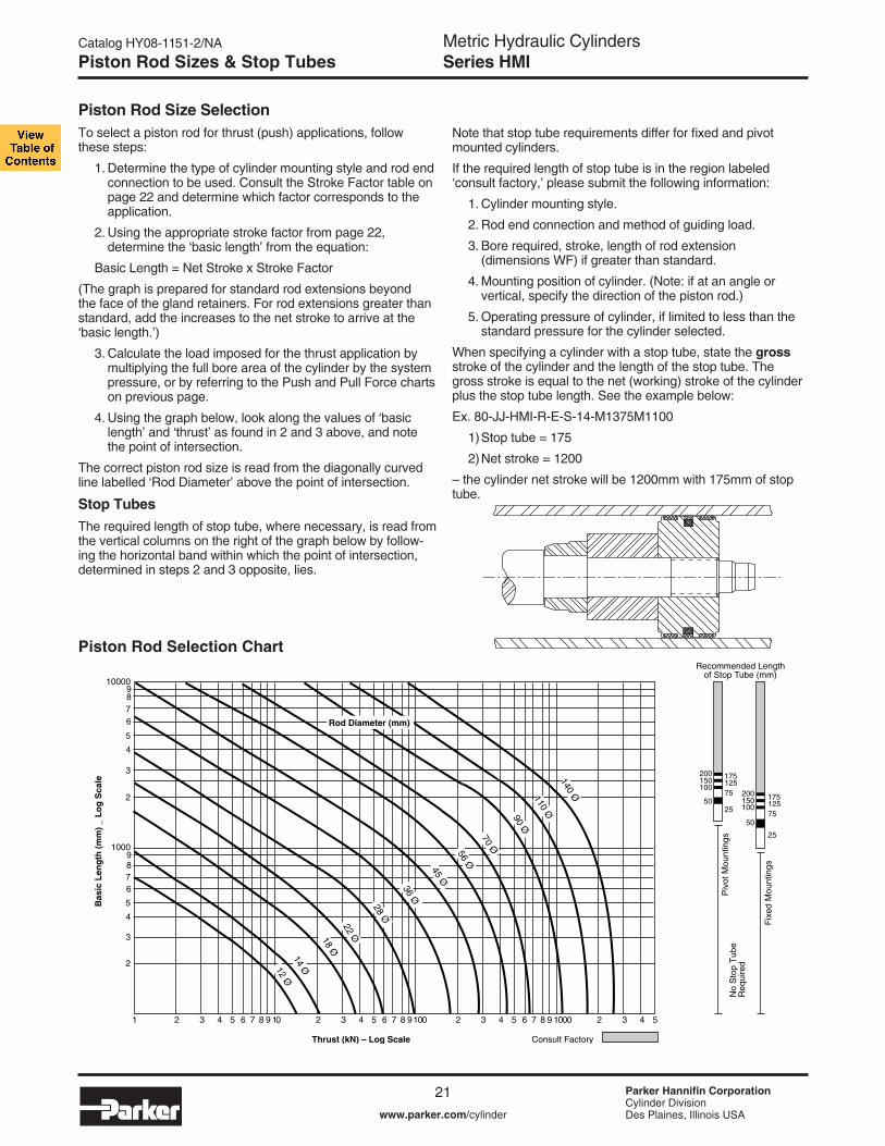
Piston Rod Size SelectionTo select a piston rod for thrust (push) applications, follow these steps:
1. Determine the type of cylinder mounting style and rod end connection to be used. Consult the Stroke Factor table on page 22 and determine which factor corresponds to the application.
2. Using the appropriate stroke factor from page 22, determine the ‘basic length’ from the equation:
Basic Length = Net Stroke x Stroke Factor
(The graph is prepared for standard rod extensions beyond the face of the gland retainers. For rod extensions greater than standard, add the increases to the net stroke to arrive at the ‘basic length.’)
3. Calculate the load imposed for the thrust application by multiplying the full bore area of the cylinder by the system pressure, or by referring to the Push and Pull Force charts on previous page.
4. Using the graph below, look along the values of ‘basic length’ and ‘thrust’ as found in 2 and 3 above, and note the point of intersection.
The correct piston rod size is read from the diagonally curved line labelled ‘Rod Diameter’ above the point of intersection.
Stop TubesThe required length of stop tube, where necessary, is read from the vertical columns on the right of the graph below by follow-ing the horizontal band within which the point of intersection, determined in steps 2 and 3 opposite, lies.
Note that stop tube requirements differ for fixed and pivot mounted cylinders.
If the required length of stop tube is in the region labeled ‘consult factory,’ please submit the following information:
1. Cylinder mounting style.
2. Rod end connection and method of guiding load.
3. Bore required, stroke, length of rod extension (dimensions WF) if greater than standard.
4. Mounting position of cylinder. (Note: if at an angle or vertical, specify the direction of the piston rod.)
5. Operating pressure of cylinder, if limited to less than the standard pressure for the cylinder selected.
When specifying a cylinder with a stop tube, state the gross stroke of the cylinder and the length of the stop tube. The gross stroke is equal to the net (working) stroke of the cylinder plus the stop tube length. See the example below:
Ex. 80-JJ-HMI-R-E-S-14-M1375M1100
1) Stop tube = 175
2) Net stroke = 1200
– the cylinder net stroke will be 1200mm with 175mm of stop tube.
Piston Rod Selection Chart
1000
10000
8
8
9
9
7
7
6
6
5
5
4
4
3
3
2
2
1 2 3 4 5 6 7 8 9 10 2 3 4 5 6 7 8 9100 2 3 4 5 6 7 8 9 1000 2 3 4 5
Rod Diameter (mm)
Thrust (kN) – Log Scale Consult Factory
Fix
ed M
ount
ings
Piv
ot M
ount
ings
2550
100150200
50
10015020075
125175
25
75125175
No
Sto
p T
ube
Req
uire
d
Recommended Lengthof Stop Tube (mm)
Bas
ic L
eng
th (
mm
) _
Lo
g S
cale 140 Ø110 Ø90 Ø
70 Ø56 Ø
45 Ø
36 Ø
28 Ø
22 Ø18 Ø
14 Ø12 Ø
Piston Rod Sizes & Stop Tubes

Metric Hydraulic CylindersSeries HMI
22www.parker.com/cylinder
Catalog HY08-1151-2/NA
Parker Hannifin CorporationCylinder DivisionDes Plaines, Illinois USA
Stroke FactorsThe stroke factors below are used in the calculation of cylinder ‘basic length’ – see Piston Rod Size Selection.
Long Stroke CylindersWhen considering the use of long stroke cylinders, the piston rod should be of sufficient diameter to provide the necessary column strength.
For tensile (pull) loads, the rod size is selected by specifying standard cylinders with standard rod diameters and using them at or below the rated pressure.
For long stroke cylinders under compressive loads, the use of stop tubes should be considered, to reduce bearing stress. The Piston Rod Selection Chart in this catalog provides guid-ance where unusually long strokes are required.
Rod EndConnection
Fixed and Rigidly Guided
Pivoted and Rigidly Guided
Fixed and Rigidly Guided
Pivoted and Rigidly Guided
Pivoted and Rigidly Guided
Supported but not Rigidly Guided
Pivoted and Rigidly Guided
Pivoted and Supportedbut not Rigidly Guided
MountingStyle
TB, TD, C, JJ
TB, TD, C, JJ
TC, HH
D
TC, HH, DD
TB, TD, C,JJ
B, BB, DB, SB
DD
StrokeFactor
0.5
0.7
1.0
1.0
1.5
2.0
2.0
3.0
Type of Mounting
Stroke Factors

Metric Hydraulic CylindersSeries HMI
23www.parker.com/cylinder
Catalog HY08-1151-2/NA
Parker Hannifin CorporationCylinder DivisionDes Plaines, Illinois USA
a
FormulaCushioning calculations are based on the formula E = 1/2mv2 for horizontal applications. For inclined or vertically downward or upward applications, this is modified to:
E = 1/2mv2 + mgl x 10-3 x sin a
(for inclined or vertically downward direction of mass)
E = 1/2mv2 – mgl x 10-3 x sin a
(for inclined or vertically upward direction of mass)
Where:
E = energy absorbed in Joulesg = acceleration due to gravity = 9.81m/s2
v = velocity in meters/secondl = length of cushion in millimetersm = mass of load in kilograms (including piston, rod and rod end accessories)a = angle to the horizontal in degreesp = pressure in bar
ExampleThe following example shows how to calculate the energy developed by masses moving in a straight line. For non-linear motion, other calculations are required; please consult the factory. The example assumes that the bore and rod diam-eters are already appropriate for the application. The effects of fric-tion on the cylin-der and load have been ignored.
Selected bore/rod 160/70mm (No. 1 rod). Cushioning at the cap end.
Pressure = 160 barMass = 10000kgVelocity = 0.4m/sCushion length = 41mma = 45°Sin a = 0.70
E = 1/2mv2 + mgl x 10-3 x sin a
= 10000 x 0.42 + 10000 x 9.81 x 41 x 0.70 2 103
= 800 + 2815 = 3615 Joules
Note that velocity is greater than 0.3m/s; therefore, a derat-ing factor of 0.75 must be applied before comparison with the curves on the cushioning charts. Applying this factor to the calculated energy figure of 3615 Joules gives a corrected energy figure of:
3615 = 4820 Joules 0.75Comparison with the curve shows that the standard cushion can safely decelerate this load. If the calculated energy exceed that indicated by the curve, select a larger bore cylinder and re-calculate.
An Introduction to CushioningCushioning is recommended as a means of controlling the deceleration of masses, or for applications where piston speeds are in excess of 0.1m/s and the piston will make a full stroke. Cushioning extends cylinder life and reduces undesir-able noise and hydraulic shock.
Built-in “cushions” are optional and can be supplied at the head and cap ends of the cylinder without affecting its envelope or mounting dimensions.
Standard CushioningIdeal cushion performance shows an almost uniform absorp-tion of energy along the cushioning length, as shown. Many forms of cushioning exist, and each has its own specific merits
and advantages. In order to cover the majority of applica-tions, HMI cylinders are supplied with profiled cushion-ing as standard. Final speed may be adjusted using the cushion screws. The performance of profiled cushioning is indicated on the diagram, and cush-ion performance for
each of the rod sizes available is illustrated graphically in the charts on the next page.
Note: Cushion performance will be affected by the use of water or high water based fluids. Please consult the factory for details.
Cushion LengthWhere specified, HMI cylinders incorporate the longest cush-ion sleeve and spear that can be accommodated within the standard envelope without reducing the rod bearing and piston bearing lengths. See table of cushion lengths on page 25. Cushions are adjustable via recessed needle valves.
Cushion CalculationsThe charts on the next page show the energy absorption capacity for each bore/rod combination at the head (annulus) and the cap (full bore) ends of the cylinder. The charts are valid for piston velocities in the range 0.1 to 0.3m/s. For velocities between 0.3 and 0.5m/s, the energy values derived from the charts should be reduced by 25%. For velocities of less than 0.1m/s where large masses are involved, and for velocities of greater than 0.5m/s, a special cushion profile may be required. Please consult the factory for details.
The cushion capacity of the head end is less than that of the cap, and reduces to zero at high drive pressures due to the pressure intensification effect across the piston.
The energy absorption capacity of the cushion decreases with drive pressure.
Cus
hion
Pre
ssur
e
Typical Straight Cushion
Cushion Position
Ideal Cushion
Typical Stepped Cushion
Cushioning

Metric Hydraulic CylindersSeries HMI
24www.parker.com/cylinder
Catalog HY08-1151-2/NA
Parker Hannifin CorporationCylinder DivisionDes Plaines, Illinois USA
Cushion Energy Absorption Capacity DataThe cushion energy absorption capacity data shown below is based on the maximum fatigue-free pressure developed in the tube. For applications with a life cycle of
less than 106 cycles, greater energy absorption figures can be applied. Please consult the factory if further information is required.
Head End
Cap End
10,000
30,000
Energy(Joules)
Drive pressure (bar)
5,000
1,000
500
100
50
100 40 80 120 160 200
Rod No.1 – HMI
200 / 90
160 / 70
125 / 56
100 / 45
80 / 36
50 / 22
40 / 18
32 / 14
25 / 12
63 / 28
10,000
30,000
Energy(Joules)
Drive pressure (bar)
5,000
1,000
500
100
50
100 40 80 120 160 200
Rod No.2 – HMI
200 / 140
160/110
125 / 90
100 / 70
80 / 56
63 / 45
50 / 36
40 / 28
32 / 22
25 / 18
10,000
30,000
Energy(Joules)
Drive pressure (bar)
5,000
1,000
500
100
50
100 40 80 120 160 200
Rod No.1 – HMI
200 / 90
160 / 70
125 / 56
100 / 45
80 / 36
63 / 28
50 / 22
40 / 18
32 / 1425 / 12
10,000
30,000
Energy(Joules)
Drive pressure (bar)
5,000
1,000
500
100
50
100 40 80 120 160 200
Rod No.2 – HMI
200 / 140
160 / 110
125 / 90100 / 7080 / 5663 / 45
50 / 36
40 / 28
32 / 2225 / 18
10,000
30,000
Energy(Joules)
Drive pressure (bar)
5,000
1,000
500
100
50
100 40 80 120 160 200
Rod No.3 – HMI
200 / 110
160 / 90
125 / 70100 / 5680 / 4563 / 36
50 / 28
10,000
30,000
Energy(Joules)
Drive pressure (bar)
5,000
1,000
500
100
50
100 40 80 120 160 200
Rod No.3 – HMI
200 / 110
160 / 90
125 / 70
100 / 56
80 / 45
63 / 36
50 / 28
Cushioning

Metric Hydraulic CylindersSeries HMI
25www.parker.com/cylinder
Catalog HY08-1151-2/NA
Parker Hannifin CorporationCylinder DivisionDes Plaines, Illinois USA
Cap
–
–
–
29
29
32
32
32
41
56
Head Head
24
24
29
29
29
27
26
27
34
49
Rod No.121212123123123123123123123
BoreØ
ISORod No. 3Rod No. 1
Cushion Length, Piston and Rod Mass
Pressure Limitations – IntroductionThe pressure limitations of a hydraulic cylinder must be reviewed when considering its application. To assist the designer in obtaining the optimum performance from a cylinder, the information which follows highlights the recommended minimum and maximum pressures according to application. If in doubt, please consult the factory.
Minimum PressureDue to factors such as seal friction, the minimum oper-ating pressure for HMI cylinders is 5 bar. Below this pressure, low friction seals should be specified. If in doubt, please consult the factory.
Maximum PressureHMI cylinders are designed to the mounting dimensions specified in ISO 6020/2 for 160 bar cylinders but, due to the selection of materials, they can be used at higher pressures depending on the application and the choice of rod size and rod end style. As a result, the majority of these cylinders can be operated at 210 bar.All dimensions are in millimeters unless otherwise state.
Cylinder Body (Pressure Envelope)In many applications, the pressure developed within a cylinder may be greater than the working pressure, due to pressure intensification across the piston and cushioning. In most cases, this intensification does not affect the cylinder mountings or piston rod threads in the form of increased loading. It may, however, affect the cylinder body and induce fatigue failure or cause premature seal wear. It is important, therefore, that the pressure due to cushioning or intensification does not exceed the 340 bar fatigue limit of the cylinder body. The cushion energy absorption data on the previous page is based on this maximum induced pressure. If in doubt, please consult the factory.
RodØ121814221828223628284536365645457056569070701109090140110
Rod Only per10mm Stroke
kg0.010.020.010.030.020.050.030.050.080.050.080.120.080.120.190.120.190.300.190.300.500.300.500.750.500.751.23
Cushion Length - ISO Piston & Rod Zero Stroke
kg0.120.160.230.300.440.600.700.800.951.201.351.602.302.502.904.004.405.107.108.009.4013.7015.3017.2027.0030.0034.00
Head
–
–
–
29
29
35
29
27
34
50
Rod No. 2Cap
20
20
30
29
29
32
32
32
41
56
Cap
20
20
29
29
29
32
32
32
41
56
25
32
40
50
63
80
100
125
160
200
22
24
29
29
29
35
35
28
34
46
Cushioning / Pressure Limitations

Metric Hydraulic CylindersSeries HMI
26www.parker.com/cylinder
Catalog HY08-1151-2/NA
Parker Hannifin CorporationCylinder DivisionDes Plaines, Illinois USA
Standard Cylinder Ports
Piston Speed
m/s0.390.240.310.340.210.180.110.120.070.07
Standard PortsSeries HMI cylinders are supplied with BSP parallel threaded ports, of a size suitable for normal speed applications – see table opposite. HMI cylinders are also available with a variety of optional ports.
Oversize PortsFor higher speed applications. Series HMI cylinders are available with oversize BSP or metric ports to the sizes shown in the table opposite, or with extra ports in head or cap faces that are not used for mountings or cushion screws. On 25 mm and 32 mm bore cylinders, 20mm high port bosses are necessary to provide the full thread length at the cap end – see rod end dimensions for increased height at the head end. Note that Y and PJ dimensions may vary slightly to accommodate oversize ports – please contact the factory where these dimen-sions are critical.
Port Size and Piston SpeedOne of the factors which influences the speed of a hydraulic cylinder is fluid flow in the connecting lines. Due to piston rod displacement, the flow at the cap end port will be greater than that at the head end, at the same piston speed. Fluid velocity in connecting lines should be limited to 5m/s to minimize fluid turbulence, pressure loss and hydraulic shock. The tables opposite are a guide for use when determining whether cylinder ports are adequate for the application. Data shown gives piston speeds for standard and oversize ports and con-necting lines where the velocity of the fluid is 5m/s.If the desired piston speed results in a fluid flow in excess of 5 m/s in connecting lines, larger lines with two ports per cap should be considered. Parker recommends that a flow rate of 12 m/s in connecting lines should not be exceeded.
Speed LimitationsWhere large masses are involved, or piston speeds exceed 0.1m/s and the piston will make a full stroke, cushions are recommended – see cushion information. For cylinders with oversize ports and with a flow exceed-ing 8m/s into the cap end, a ‘non-floating cushion’ should be specified. Please consult the factory.
Ports, Air Bleeds and Cushion Adjustment LocationThe table below shows standard positions for ports, and cushion adjusting screws where fitted. Air bleeds (see optional features) may be fitted in unoccupied faces of the head or cap, depending on mounting.
1Not to DIN 24 554220mm high port bosses fitted at cap end3ISO 6149 ports are not available on some bore/rod combinations4Consult factory – not normally available on these bore sizesNot recommended for JJ mountings at pressures above 100 bar
Bore ofConnecting
Lines77
1013131515191924
BoreØ253240506380
100125160200
PortSize
BSP/GInches
1/41/43/81/21/23/43/411
1 1/4
Cap EndFlow in l/min
@ 5m/s11.511.523.5404053538585
136
PortSize
Metric1
M14x1.5M14x1.5M18x1.5M22x1.5M22x1.5M27x2M27x2M33x2M33x2M42x2
Oversize Cylinder Ports (Not to DIN)
Piston Speed
m/s0.800.480.530.450.280.280.180.180.110.11
Bore ofConnecting
Lines10101315151919242430
BoreØ2532405063804
1004
1254
1604
2004
PortSize
BSP/GInches
3/82
3/82
1/23/43/411
1 1/41 1/41 1/2
Cap EndFlow in l/min
@ 5m/s23.523.54053538585
136136212
PortSize
Metric1
M18x1.52,3
M18x1.52,3
M22x1.53
M27x23
M27x23
M33x2M33x2M42x2M42x2M48x2
4 2
1
3
Positions of Ports Mounting Styles
and Cushion Screws TB, TC and JJ HH C5 B and BB SB D DB DD in Head and Cap TD
Port 1 2 3 4 1 2 3 4 1 2 3 4 1 2 4 1 2 3 4 1 2 3 4 1 3 1 2 3 4 1 2 3 4 Head Cushion 2 3 4 1 3 3 1 1 3 4 1 2 2 4 2 2 3 4 1 2 3 4 1 3 1 3 4 1 2 3 4 1 2
Port 1 2 3 4 1 2 3 4 1 2 3 4 1 2 4 1 2 3 4 1 2 3 4 1 2 3 4 1 3 1 2 3 4 Cap Cushion 2 3 4 1 3 4 1 2 3 3 1 1 2 4 2 2 3 4 1 2 3 4 1 3 4 1 2 3 1 3 4 1 2
All dimensions are in millimeters unless otherwise stated.
5Ports at position 2 or 4 in 25mm to 100mm bores are offset toward position 1.
Ports at position 2 or 4 in 25mm to 100mm bore sizes of mounting style C are offset toward position 1 and are not available in the head of 25mm and 32mm bores with number 2 rods. 25mm and 32mm bore heads will not be elongated 5mm toward position 2 or 4 when a port is specified at either of those two locations (the 5mm elongation at position 1 will remain). Contact the factory for the offset dimension.
Ports, Locations and Piston Speeds

Metric Hydraulic CylindersSeries HMI
27www.parker.com/cylinder
Catalog HY08-1151-2/NA
Parker Hannifin CorporationCylinder DivisionDes Plaines, Illinois USA
DD
kg1.51.6
2.0
4.64.77.9
8.0
10.610.710.9
20.5
20.7
Cylinder Port OptionsOption “T” SAE Straight Thread O-Ring Port.
Recommended for most hydraulic applications.
Option “U” Conventional NPTF Ports (Dry-Seal Pipe Threads). Recommended for pneumatic applications only.
Option “R” BSPP Port (British Parallel Thread).ISO 228 port commonly used in Europe.See Figure R-G below.
Option “P” SAE Flange Ports Code 61 (3000 psi). Recommended for hydraulic applications requiring larger port sizes.
Option “B” BSPT (British Tapered Thread).
Option “M” Metric Straight Thread Port similar to Option “R” with metric thread. Popular in some European applications. See Figure R-G below.
Option “Y” ISO-6149-1 Metric Straight Thread Port.Recommended for all hydraulic applications designed per ISO standards. See Figure Y below.
“R”BSPP
Parallel Thread(Standard)
1/41/43/81/21/23/43/411
1 1/4
“U”NPTFPipe
Thread1/41/43/81/21/23/43/411
1 1/4
“T”SAE
#6#6#6#10#10#12#12#16#16#20
BoreØ
253240506380100125160200
“Y”ISO-6149-1
Metric Straight Thread
M14 x 1.5M14 x 1.5M18 x 1.5M22 x 1.5M22 x 1.5M27 x 2M27 x 2M33 x 2M33 x 2M42 x 2
“M”Metric Straight
Thread
M14 x 1.5M14 x 1.5M18 x 1.5M22 x 1.5M22 x 1.5M27 x 2M27 x 2M33 x 2M33 x 2M42 x 2
“B”BSPTTaper
Thread1/41/43/81/21/23/43/411
1 1/4
“P”SAE 4-Bolt
FlangeNom. Size
N/AN/AN/AN/A
1/21, 2
3/41
3/411
1 1/4
BSPP Port for Series HMI
Figure R-G
ISO 6149-1 Port for Series HMI
Figure Y
POSSIBLETYPES OF SEALS SEALING SURFACE
B,BB,SB
kg
1.4
1.9
4.24.37.07.17.210.110.210.419.519.619.8
C
kg
1.4
1.9
4.04.16.5
6.6
9.79.89.917.317.417.7
BoreØ
25
32
40
50
63
80
RodØ
121814221828222836283645364556
D, DB
kg
1.3
1.7
3.94.0
6.3
6.48.99.09.116.516.616.8
Weightper
10mmStroke
kg0.050.060.060.080.090.120.140.160.180.190.220.270.270.320.39
JJ, HH
kg
1.5
2.0
4.74.87.2
7.3
10.110.210.318.919.019.2
TB, TCTD
kg
1.2
1.61.73.73.85.9
6.0
8.58.68.716.016.116.3
Mounting Styles – Weight at Zero Stroke
Weights – Series HMI Cylinders
All dimensions are in millimeters unless otherwise stated.
IDENTIFICATION MARK ORSURFACE “A” IS MARKED METRIC
SURFACE “A”
B,BB,SB
kg
28.0
29.053.0
54.0
90.091.092.0157.0158.0160.0
C
kg
24.0
25.044.0
45.0
73.0
74.0129.0130.0131.0
DD
kg26.0
27.0
48.049.050.084.0
85.0
153.0
155.0
BoreØ
100
125
160
200
RodØ
455670567090709011090110140
D, DB
kg
22.7
23.2
43.0
44.071.0
72.0
127.0128.0129.0
Weightper
10mmStroke
kg0.400.470.580.650.760.951.001.201.401.501.802.30
JJ, HH
kg25.0
26.0
48.0
49.0
78.0
79.0
138.0
140.0
TB, TCTD
kg
22.0
23.0
42.0
43.0
69.0
70.0122.0123.0124.0
Mounting Styles – Weight at Zero Stroke
Ports / Weights
1 Due to flange mounting-bolt interference, this port can only be supplied on the cap end of Mounting Styles TC & TD when tie rod nuts are not recessed.2 SAE 4-Bolt Flange Port is not available on the head end in 63mm bore with Rod No. 2 (45mm).
Metric Hydraulic CylindersSeries HMI
28www.parker.com/cylinder
Catalog HY08-1151-2/NA
Parker Hannifin CorporationCylinder DivisionDes Plaines, Illinois USA
Operating MediumSealing materials used in the standard cylinder are suit-able for use with most petroleum-based hydraulic fluids.Special seals are available for use with water-glycol or oil in water emulsions, and with fluids such as fire- resistant synthetic phosphate ester and phosphate ester-based fluids.If there is any doubt regarding seal compatibility with the operating medium, please consult the factory.The table above is a guide to the sealing compounds and operating parameters of the materials used for standard and optional rod gland, piston and body seals
TemperatureStandard seals can be operated at temperatures between -20°C and +80°C. Where operating conditions result in temperatures which exceed these limits, spe-cial seal compounds may be required to ensure satis-factory service life – please consult the factory.
Special SealsGroup 1 seals are fitted as standard to HMI cylinders. For other duties, optional seal groups 2, 5 & 6 are avail-able – please see the cylinder order code for HMI (ISO) cylinders. Special seals, in addition to those shown in the table above, can also be supplied. Please insert an S (Special) in the order code and specify fluid medium when ordering.
Water ServiceSpecial cylinders are available for use with water as the fluid medium. Modifications include a stainless steel piston rod with lipseal piston, and plating of internal surfaces. When ordering, please specify the maximum operating pressure or load/speed conditions.
WarrantyParker Hannifin warrants cylinders modified for use with water or water base fluids to be free of defects in materi-als and workmanship, but cannot accept responsibility for premature failure caused by corrosion, electrolysis or mineral deposits in the cylinder.
Metallic Rod WipersMetallic rod wipers replace the standard wiper seal, and are recommended where dust or splashings might damage the wiper seal material. Metallic rod wipers do not affect cylinder dimensions.
Proximity SensorsEPS proximity switches can be fitted to give reliable end of stroke signals.
Position FeedbackLinear position transducers of various types are avail-able for Series HMI cylinders. Please contact the fac-tory for further details.
Rod End BellowsUnprotected piston rod surfaces which are exposed to contaminants with air hardening properties can be pro-tected by rod end bellows. Longer rod extensions are required to accommodate the collapsed length of the bellows. Please consult the factory for further information.
Seals and Fluid DataGroup
1
25
6
Seal Materials – a combination of:Nitrile (NBR), PTFE,enhanced polyurethane (AU)Nitrile, PTFEFluorocarbon elastomer (FPM)Fluorocarbon, PTFE
Nitrile (NBR), PTFE,enhanced polyurethane (AU)
Fluid Medium to ISO 6743/4-1982Mineral oil HH, HL, HLP, HLP-D, HM, HV, MIL-H-5606 oil, nitrogen
Water Glycol (HFC)Fire resistant fluids based on phosphate esters (HFD-R) Also suitable for hydraulic oil at high temperatures/environments.Not suitable for use with Skydrol. See fluid manufacturer’s recommendations.Oil in water emulsion 95/5 (HFA)
Temperature Range-20°C to + 80°C
-20°C to + 60°C-20°C to + 150°C
+5°C to +55°C
Low Friction SealsFor applications where very low friction and an absence of stick-slip are important, the option of low friction seals is available. Please consult the factory.
Seals and Fluids / Optional Features

Metric Hydraulic CylindersSeries HMI
29www.parker.com/cylinder
Catalog HY08-1151-2/NA
Parker Hannifin CorporationCylinder DivisionDes Plaines, Illinois USA
Gland DrainsThe tendency of hydraulic fluid to adhere to the piston rod can result in an accumulation of fluid in the cavity behind the gland wiperseal under certain operating conditions. This may occur with long stroke cylinders; where there is a constant back pressure as in differential circuitry, or where the ratio of the extend speed to the retract speed is greater than 2 to 1.
A gland drain port is provided in the retainer, except in mount-ing style JJ, style D in 100mm to 200mm bores, and regard-less of mounting style, 25mm bore with all rod numbers, and 32mm to 40mm bores with number 1 rod. In these cases the drain port is located in the head. When the gland drain port in 25mm to 40mm bores is in the head of all mounting styles except JJ, it must be in the same position as the port (on the 5mm elongated side for 25mm & 32mm bores) and when specified in 25mm and 32mm bores of mounting style C it must be in position 1. On JJ mounting styles in 25mm and 32mm bores the drain port can be in position 2 or 4 and is not available in position 3. When the gland drain port is provided in the retainer, the thickness of the retainer is increased by 6mm in 32mm and 40mm bores with number 2 rod and by 4mm in 63mm bore cylinders with number 2 rod. Note that, on style JJ cylinders, drain ports cannot normally be posi-tioned in the same face as ports or cushion valves – please consult the factory.
Air BleedsThe option of bleed screws is available at either or both ends of the cylinder, at any position except in the port face. The selected positions should be shown in the order code. Cylinders with bore sizes up to 40mm are fitted with M5 bleed screws; for bore sizes of 50mm and above, M8 bleed screws are fitted. Note that, for cylinders of 50mm bore and above, where it is essential to have the air bleed in the port face, bosses can be welded to the cylinder tube. Please contact the factory for details.
Spring-Returned, Single-Acting CylindersSeries HMI single-acting cylinders can be supplied with an internal spring to return the piston after the pressure stroke. Please supply details of load conditions and friction factors, and advise whether the spring is required to advance or return the piston rod.
On spring-returned cylinders, tie rod extensions will be sup-plied to allow the spring to be ‘backed off’ until compression is relieved. Tie rod nuts will be welded to the tie rods at the opposite end of the cylinder, to further assure safe disassem-bly. Please contact the factory when ordering spring-returned cylinders.
Duplex and Tandem CylindersA tandem cylinder is made up of two cylinders mounted in line with pistons connected by a common piston rod and rod seals installed between the cylinders to permit double acting operation of each. Tandem cylinders allow increased output force when mounting width or height are restricted.
A duplex cylinder is made up of two cylinders mounted in line with pistons not connected with rod seals installed between the cylinders to permit double acting operation of each. Cylinders may be mounted with piston rod to piston or back to back and are generally used to provide three position operation.
All dimensions are in millimeters unless otherwise stated.2 Infrequent is defined by positioning the retract stroke in a couple of attempts at original machine set up. The frequent stroke adjuster is recommended for adjustments required after the original equipment has been adjusted by the original machine manufacturer.
Port Type Port Size R (BSPP) 1/8 BSPP
T (SAE) #4 (SAE)
U 1/8 NPTF (Pipe Thread)
M M10 x 1 (Metric Straight)
Y (ISO 6149-1) M10 x 1
B (BSPT) 1/8 BSPT
P (SAE 4 1/8 BSPP Bolt Flange)
Bore D J K L Ø min max
40 M12x1.25 7 75 130
50 M20x1.5 12 75 200
63 M27x2 16 75 230
80 M33x2 20 85 230
100 M42x2 26 70 450
125 M48x2 30 70 500
160 M64x3 40 75 500
200 M80x3 50 80 500
Stroke AdjustersWhere absolute precision in stroke length is required, a screwed adjustable stop can be supplied. Several types are available – the illustration shows a design suitable for infrequent2 adjustment at the uncushioned cap end of a cylinder. Please contact the factory, specifying details of the application and the adjustment required.
Seal
D Threads
L max
J Wrench Square
K
Gland drain ports will be the same type as the ports specified on the cylinder assembly except for non “JJ” mounts on bore sizes 25, 32, 40 and 50 mm. In these cases they will be 1/8 NPTF.
The size of the gland drain ports are as shown on the adjacent table.
Gland drains should be piped back to the fluid reservoir, which should be located below the level of the cylinder.
Gland Drain Port Location & Position AvailabilityBore
ØRod
ØHead (H) or Retainer (R) Location / Position
TB, TC, TD, HH, B, BB, SB,
DB, DD
C D JJ
25 All H / 1, 2, 3, 4 H / 1 H / 1, 3 H / 2, 4
32 14 H / 1, 2, 3, 4 H / 1 H / 1, 3 H / 2, 4
22 R / 1, 2, 3, 4 R / 1, 2, 31, 4 R / 1, 2, 3, 4 H / 2, 4
40 18 H / 1, 2, 3, 4 H / 1 H / 1, 3 H / 2, 3, 4
28 R / 1, 2, 3, 4 R / 1, 2, 3, 4 R / 1, 2, 3, 4 H / 2, 3, 4
50 All R / 1, 2, 3, 4 R / 1, 2, 3, 4 R / 1, 2, 3, 4 H / 2, 3, 4
63 All R / 1, 2, 3, 4 R / 1, 2, 3, 4 R / 1, 2, 3, 4 H / 2, 3, 4
80 All R / 1, 2, 3, 4 R / 1, 2, 3, 4 R / 1, 2, 3, 4 H / 2, 3, 4
100 All R / 1, 2, 3, 4 R / 1, 2, 3, 4 H / 1, 3 H / 2, 3, 4
125 All R / 1, 2, 3, 4 R / 1, 2, 3, 4 H / 1, 3 H / 2, 3, 4
160 All R / 1, 2, 3, 4 R / 1, 2, 3, 4 H / 1, 3 H / 2, 3, 4
200 All R / 1, 2, 3, 4 R / 1, 2, 3, 4 H / 1, 3 H / 2, 3, 41 Gland drain is not available in position 3 when key plate is specified.
Optional Features

Metric Hydraulic CylindersSeries HMI
30www.parker.com/cylinder
Catalog HY08-1151-2/NA
Parker Hannifin CorporationCylinder DivisionDes Plaines, Illinois USA
Cylinder Safety Guide
Before selecting or using Parker Hannifin Corporation (the Company) cylinders or related accessories, it is important that you read, understand and follow the following safety information. Training is advised before selecting and using the Company’s products.
1.0 General Instructions 1.1 Scope – This safety guide provides instructions for selecting and using
(including assembling, installing, and maintaining) cylinder products. This safety guide is a supplement to and is to be used with the specific Company publications for the specific cylinder products that are being considered for use.
1.2 Fail Safe – Cylinder products can and do fail without warning for many reasons. All systems and equipment should be designed in a fail-safe mode so that if the failure of a cylinder product occurs people and property won’t be endangered.
1.3 Distribution – Provide a free copy of this safety guide to each person responsible for selecting or using cylinder products. Do not select or use the Company’s cylinders without thoroughly reading and understanding this safety guide as well as the specific Company publications for the products considered or selected.
1.4 User Responsibility – Due to very wide variety of cylinder applications and cylinder operating conditions, the Company does not warrant that any particular cylinder is suitable for any specific application. This safety guide does not analyze all technical parameters that must be considered in select-ing a product. The hydraulic and pneumatic cylinders outlined in this catalog are designed to the Company’s design guidelines and do not necessarily meet the design guideline of other agencies such as American Bureau of Shipping, ASME Pressure Vessel Code etc. The user, through its own analysis and testing, is solely responsible for:
• Making the final selection of the cylinders and related accessories. • Determining if the cylinders are required to meet specific design require-
ments as required by the Agency(s) or industry standards covering the design of the user’s equipment.
• Assuring that the user’s requirements are met, OSHA requirements are met, and safety guidelines from the applicable agencies such as but not limited to ANSI are followed and that the use presents no health or safety hazards.
• Providing all appropriate health and safety warnings on the equipment on which the cylinders are used.
1.5 Additional Questions – Call the appropriate Company technical service department if you have any questions or require any additional information. See the Company publication for the product being considered or used, or call 1-847-298-2400, or go to www.parker.com, for telephone numbers of the appropriate technical service department.
2.0 Cylinder and Accessories Selection 2.1 Seals – Part of the process of selecting a cylinder is the selection of
seal compounds. Before making this selection, consult the “seal information page(s)” of the publication for the series of cylinders of interest.
The application of cylinders may allow fluids such as cutting fluids, wash down fluids etc. to come in contact with the external area of the cylinder. These fluids may attack the piston rod wiper and or the primary seal and must be taken into account when selecting and specifying seal compounds.
Dynamic seals will wear. The rate of wear will depend on many operating factors. Wear can be rapid if a cylinder is mis-aligned or if the cylinder has been improperly serviced. The user must take seal wear into consideration in the application of cylinders.
2.2 Piston Rods – Possible consequences of piston rod failure or separation of the piston rod from the piston include, but are not limited to are:
• Piston rod and or attached load thrown off at high speed. • High velocity fluid discharge. • Piston rod extending when pressure is applied in the piston
retract mode.
Piston rods or machine members attached to the piston rod may move suddenly and without warning as a consequence of other conditions occurring to the machine such as, but not limited to:
• Unexpected detachment of the machine member from the piston rod.
• Failure of the pressurized fluid delivery system (hoses, fittings, valves, pumps, compressors) which maintain cylinder position.
• Catastrophic cylinder seal failure leading to sudden loss of pressurized fluid.
• Failure of the machine control system. Follow the recommendations of the “Piston Rod Selection Chart and Data”
in the publication for the series of cylinders of interest. The suggested piston rod diameter in these charts must be followed in order to avoid piston rod buckling.
Piston rods are not normally designed to absorb bending moments or loads which are perpendicular to the axis of piston rod motion. These additional loads can cause the piston rod to fail. If these types of additional loads are expected to be imposed on the piston rod, their magnitude should be made known to our engineering department.
The cylinder user should always make sure that the piston rod is securely attached to the machine member.
On occasion cylinders are ordered with double rods (a piston rod extended from both ends of the cylinder). In some cases a stop is threaded on to one of the piston rods and used as an external stroke adjuster. On occasions spacers are attached to the machine member connected to the piston rod and also used as a stroke adjuster. In both cases the stops will create a pinch point and the user should consider appropriate use of guards. If these external stops are not perpendicular to the mating contact surface, or if debris is trapped between the contact surfaces, a bending moment will be placed on the piston rod, which can lead to piston rod failure. An external stop will also negate the effect of cushioning and will subject the piston rod to impact loading. Those two (2) conditions can cause piston rod failure. Internal stroke adjusters are available with and without cushions. The use of external stroke adjusters should be reviewed with our engineering department.
The piston rod to piston and the stud to piston rod threaded connections are secured with an anaerobic adhesive. The strength of the adhesive decreases with increasing temperature. Cylinders which can be exposed to tempera-tures above +250°F (+121°C) are to be ordered with a non studded piston rod and a pinned piston to rod joint.
2.3 Cushions – Cushions should be considered for cylinder applications when the piston velocity is expected to be over 4 inches/second.
Cylinder cushions are normally designed to absorb the energy of a linear applied load. A rotating mass has considerably more energy than the same mass moving in a linear mode. Cushioning for a rotating mass application should be reviewed by our engineering department.
2.4 Cylinder Mountings – Some cylinder mounting configurations may have certain limitations such as but not limited to minimum stroke for side or foot mounting cylinders or pressure de-ratings for certain mounts. Carefully review the catalog for these types of restrictions.
Always mount cylinders using the largest possible high tensile alloy steel socket head cap screws that can fit in the cylinder mounting holes and torque them to the manufacturer’s recommendations for their size.
2.5 Port Fittings – Hydraulic cylinders applied with meter out or decelera-tion circuits are subject to intensified pressure at piston rod end.
The rod end pressure is approximately equal to:
operating pressure x effective cap end area effective rod end piston area
Contact your connector supplier for the pressure rating of individual connectors.
3.0 Cylinder and Accessories Installation and Mounting 3.1 Installation 3.1.1 – Cleanliness is an important consideration, and cylinders are
shipped with the ports plugged to protect them from contaminants enter-ing the ports. These plugs should not be removed until the piping is to be installed. Before making the connection to the cylinder ports, piping should be thoroughly cleaned to remove all chips or burrs which might have resulted from threading or flaring operations.
Safety Guide for Selecting and Using Hydraulic, Pneumatic Cylinders and Their Accessories
WARNING: FAILURE OF THE CYLINDER, ITS PARTS, ITS MOUNTING, ITS CONNECTIONS TO OTHER OBJECTS, OR ITS CONTROLS CAN RESULT IN: • Unanticipated or uncontrolled movement of the cylinder or objects connected to it. • Falling of the cylinder or objects held up by it. • Fluid escaping from the cylinder, potentially at high velocity.THESE EVENTS COULD CAUSE DEATH OR PERSONAL INJURY BY, FOR EXAMPLE, PERSONS FALLING FROM HIGH LOCATIONS, BEING CRUSHED OR STRUCK BY HEAVY OR FAST MOVING OBJECTS, BEING PUSHED INTO DANGEROUS EQUIPMENT OR SITUATIONS, OR SLIPPING ON ESCAPED FLUID.

Metric Hydraulic CylindersSeries HMI
31www.parker.com/cylinder
Catalog HY08-1151-2/NA
Parker Hannifin CorporationCylinder DivisionDes Plaines, Illinois USA
Cylinder Safety Guide
3.1.2 – Cylinders operating in an environment where air drying materials are present such as fast-drying chemicals, paint, or weld splatter, or other hazardous conditions such as excessive heat, should have shields installed to prevent damage to the piston rod and piston rod seals.
3.1.3 – Proper alignment of the cylinder piston rod and its mating component on the machine should be checked in both the extended and retracted positions. Improper alignment will result in excessive rod gland and/or cylinder bore wear. On fixed mounting cylinders attaching the pis-ton rod while the rod is retracted will help in achieving proper alignment.
3.1.4 – Sometimes it may be necessary to rotate the piston rod in order to thread the piston rod into the machine member. This operation must always be done with zero pressure being applied to either side of the piston. Failure to follow this procedure may result in loosening the piston to rod-threaded connection. In some rare cases the turning of the piston rod may rotate a threaded piston rod gland and loosen it from the cylinder head. Confirm that this condition is not occurring. If it does, re-tighten the piston rod gland firmly against the cylinder head.
For double rod cylinders it is also important that when attaching or detaching the piston rod from the machine member that the torque be applied to the piston rod end of the cylinder that is directly attaching to the machine member with the opposite end unrestrained. If the design of the machine is such that only the rod end of the cylinder opposite to where the rod attaches to the machine member can be rotated, consult the factory for further instructions.
3.2 Mounting Recommendations 3.2.1 – Always mount cylinders using the largest possible high tensile
alloy steel socket head screws that can fit in the cylinder mounting holes and torque them to the manufacturer’s recommendations for their size.
3.2.2 – Side-Mounted Cylinders – In addition to the mounting bolts, cylinders of this type should be equipped with thrust keys or dowel pins located so as to resist the major load.
3.2.3 – Tie Rod Mounting – Cylinders with tie rod mountings are recom-mended for applications where mounting space is limited. The standard tie rod extension is shown as BB in dimension tables. Longer or shorter extensions can be supplied. Nuts used for this mounting style should be torqued to the same value as the tie rods for that bore size.
3.2.4 – Flange Mount Cylinders – The controlled diameter of the rod gland extension on head end flange mount cylinders can be used as a pilot to locate the cylinders in relation to the machine. After align-ment has been obtained, the flanges may be drilled for pins or dowels to prevent shifting.
3.2.5 – Trunnion Mountings – Cylinders require lubricated bearing blocks with minimum bearing clearances. Bearing blocks should be carefully aligned and rigidly mounted so the trunnions will not be subjected to bending moments. The rod end should also be pivoted with the pivot pin in line and parallel to axis of the trunnion pins.
3.2.6 – Clevis Mountings – Cylinders should be pivoted at both ends with centerline of pins parallel to each other. After cylinder is mounted, be sure to check to assure that the cylinder is free to swing through its working arc without interference from other machine parts.
4.0 Cylinder and Accessories Maintenance, Troubleshooting and Replacement
4.1 Storage – At times cylinders are delivered before a customer is ready to install them and must be stored for a period of time. When storage is required the following procedures are recommended.
4.1.1 – Store the cylinders in an indoor area which has a dry, clean and noncorrosive atmosphere. Take care to protect the cylinder from both internal corrosion and external damage.
4.1.2 – Whenever possible cylinders should be stored in a vertical posi-tion (piston rod up). This will minimize corrosion due to possible conden-sation which could occur inside the cylinder. This will also minimize seal damage.
4.1.3 – Port protector plugs should be left in the cylinder until the time of installation.
4.1.4 – If a cylinder is stored full of hydraulic fluid, expansion of the fluid due to temperature changes must be considered. Installing a check valve with free flow out of the cylinder is one method.
4.1.5 – When cylinders are mounted on equipment that is stored outside for extended periods, exposed unpainted surfaces, e.g. piston rod, must be coated with a rust-inhibiting compound to prevent corrosion.
4.2 Cylinder Trouble Shooting
4.2.1 – External Leakage 4.2.1.1 – Rod seal leakage can generally be traced to worn or
damaged seals. Examine the piston rod for dents, gouges or score marks, and replace piston rod if surface is rough.
Rod seal leakage could also be traced to gland wear. If clearance is excessive, replace rod bushing and seal. Rod seal leakage can also be traced to seal deterioration. If seals are soft or gummy or brittle, check compatibility of seal material with lubricant used if air cylinder, or operating fluid if hydraulic cylinder. Replace with seal material, which is compatible with these fluids. If the seals are hard or have lost elasticity, it is usually due to exposure to temperatures in excess of 165°F. (+74°C). Shield the cylinder from the heat source to limit temperature to 350°F. (+177°C.) and replace with fluorocarbon seals.
4.2.1.2 – Cylinder body seal leak can generally be traced to loose tie rods. Torque the tie rods to manufacturer’s recommendation for that bore size.
Excessive pressure can also result in cylinder body seal leak. Determine maximum pressure to rated limits. Replace seals and retorque tie rods as in paragraph above. Excessive pressure can also result in cylinder body seal leak. Determine if the pressure rating of the cylinder has been exceeded. If so, bring the operating pressure down to the rating of the cylinder and have the tie rods replaced.
Pinched or extruded cylinder body seal will also result in a leak. Replace cylinder body seal and retorque as in paragraph above.
Cylinder body seal leakage due to loss of radial squeeze which shows up in the form of flat spots or due to wear on the O.D. or I.D. – Either of these are symptoms of normal wear due to high cycle rate or length of service. Replace seals as per paragraph above.
4.2.2 – Internal Leakage 4.2.2.1 – Piston seal leak (by-pass) 1 to 3 cubic inches per minute
leakage is considered normal for piston ring construction. Virtually no static leak with lipseal type seals on piston should be expected. Piston seal wear is a usual cause of piston seal leakage. Replace seals as required.
4.2.2.2 – With lipseal type piston seals excessive back pressure due to over-adjustment of speed control valves could be a direct cause of rapid seal wear. Contamination in a hydraulic system can result in a scored cylinder bore, resulting in rapid seal wear. In either case, replace piston seals as required.
4.2.2.3 – What appears to be piston seal leak, evidenced by the fact that the cylinder drifts, is not always traceable to the piston. To make sure, it is suggested that one side of the cylinder piston be pressurized and the fluid line at the opposite port be disconnected. Observe leakage. If none is evident, seek the cause of cylinder drift in other component parts in the circuit.
4.2.3 – Cylinder Fails to Move the Load 4.2.3.1 – Pneumatic or hydraulic pressure is too low. Check the
pressure at the cylinder to make sure it is to circuit requirements. 4.2.3.2 – Piston Seal Leak – Operate the valve to cycle the cylinder
and observe fluid flow at valve exhaust ports at end of cylinder stroke. Replace piston seals if flow is excessive.
4.2.3.3 – Cylinder is undersized for the load – Replace cylinder with one of a larger bore size.
4.3 Erratic or Chatter Operation 4.3.1 – Excessive friction at rod gland or piston bearing due to load
misalignment – Correct cylinder-to-load alignment. 4.3.2 – Cylinder sized too close to load requirements – Reduce load or
install larger cylinder. 4.3.3 – Erratic operation could be traced to the difference between
static and kinetic friction. Install speed control valves to provide a back pressure to control the stroke.
4.4 Cylinder Modifications, Repairs, or Failed Component – Cylinders as shipped from the factory are not to be disassembled and or modified. If cylinders require modifications, these modifications must be done at company locations or by the Company’s certified facilities. The Cylinder Division Engineering Department must be notified in the event of a mechanical fracture or permanent deformation of any cylinder component (excluding seals). This includes a broken piston rod, tie rod, mounting accessory or any other cylinder component. The notification should include all operation and application details. This information will be used to provide an engineered repair that will prevent recurrence of the failure.
It is allowed to disassemble cylinders for the purpose of replacing seals or seal assemblies. However, this work must be done by strictly following all the instructions provided with the seal kits.

Metric Hydraulic CylindersSeries HMI
32www.parker.com/cylinder
Catalog HY08-1151-2/NA
Parker Hannifin CorporationCylinder DivisionDes Plaines, Illinois USA
AerospaceKey MarketsAftermarket services Commercial transportsEnginesGeneral & business aviationHelicoptersLaunch vehiclesMilitary aircraftMissilesPower generation Regional transportsUnmanned aerial vehicles
Key ProductsControl systems & actuation productsEngine systems & componentsFluid conveyance systems& componentsFluid metering, delivery & atomization devicesFuel systems & componentsFuel tank inerting systemsHydraulic systems & componentsThermal managementWheels & brakes
ElectromechanicalKey MarketsAerospaceFactory automationLife science & medicalMachine toolsPackaging machineryPaper machineryPlastics machinery & convertingPrimary metalsSemiconductor & electronicsTextileWire & cable
Key ProductsAC/DC drives & systemsElectric actuators, gantry robots & slidesElectrohydrostatic actuation systemsElectromechanical actuation systemsHuman machine interfaceLinear motorsStepper motors, servo motors, drives & controlsStructural extrusions
PneumaticsKey MarketsAerospaceConveyor & material handlingFactory automationLife science & medicalMachine toolsPackaging machineryTransportation & automotive
Key ProductsAir preparationBrass fittings & valvesManifoldsPneumatic accessoriesPneumatic actuators & grippersPneumatic valves & controlsQuick disconnectsRotary actuatorsRubber & thermoplastic hose & couplingsStructural extrusionsThermoplastic tubing & fittingsVacuum generators, cups & sensors
Fluid & Gas HandlingKey Markets Aerial liftAgricultureBulk chemical handlingConstruction machineryFood & beverageFuel & gas deliveryIndustrial machineryLife sciences MarineMiningMobileOil & gasRenewable energyTransportation
Key Products Check valves Connectors for low pressure fluid conveyanceDeep sea umbilicalsDiagnostic equipment Hose couplingsIndustrial hoseMooring systems & power cablesPTFE hose & tubing Quick couplingsRubber & thermoplastic hose Tube fittings & adaptersTubing & plastic fittings
HydraulicsKey Markets Aerial liftAgricultureAlternative energyConstruction machineryForestryIndustrial machineryMachine toolsMarineMaterial handlingMiningOil & gasPower generationRefuse vehiclesRenewable energyTruck hydraulicsTurf equipment
Key Products AccumulatorsCartridge valvesElectrohydraulic actuatorsHuman machine interfacesHybrid drivesHydraulic cylinders Hydraulic motors & pumpsHydraulic systemsHydraulic valves & controlsHydrostatic steeringIntegrated hydraulic circuitsPower take-offs Power unitsRotary actuatorsSensors
Process ControlKey Markets Alternative fuelsBiopharmaceuticalsChemical & refiningFood & beverageMarine & shipbuildingMedical & dentalMicroelectronicsNuclear PowerOffshore oil explorationOil & gasPharmaceuticalsPower generationPulp & paperSteelWater/wastewater
Key ProductsAnalytical Instruments Analytical sample conditioningproducts & systemsChemical injection fittings& valvesFluoropolymer chemicaldelivery fittings, valves & pumpsHigh purity gas delivery fittings, valves, regulators& digital flow controllersIndustrial mass flow meters/controllersPermanent no-weld tube fittingsPrecision industrial regulators& flow controllersProcess control double block & bleedsProcess control fittings, valves, regulators & manifold valves
Sealing & ShieldingKey Markets AerospaceChemical processingConsumerFluid powerGeneral industrialInformation technologyLife sciencesMicroelectronicsMilitaryOil & gasPower generationRenewable energyTelecommunicationsTransportation
Key Products Dynamic sealsElastomeric o-ringsElectro-medical instrumentdesign & assemblyEMI shieldingExtruded & precision-cut,fabricated elastomeric sealsHigh temperature metal sealsHomogeneous & insertedelastomeric shapesMedical device fabrication & assemblyMetal & plastic retainedcomposite sealsShielded optical windowsSilicone tubing & extrusionsThermal managementVibration dampening
Parker’s Motion & Control Technologies
At Parker, we’re guided by
a relentless drive to help
our customers become more
productive and achieve
higher levels of profitabil-
ity by engineering the best
systems for their require-
ments. It means looking at
customer applications from
many angles to find new
ways to create value. What-
ever the motion and control
technology need, Parker has
the experience, breadth of
product and global reach
to consistently deliver. No
company knows more about
motion and control technol-
ogy than Parker. For further
info call 1 800 C-Parker
(1 800 272 7537)
Climate ControlKey Markets AgricultureAir conditioningConstruction MachineryFood & beverageIndustrial machineryLife sciencesOil & gasPrecision coolingProcessRefrigerationTransportation
Key Products AccumulatorsAdvanced actuatorsCO
2 controls
Electronic controllersFilter driersHand shut-off valvesHeat exchangers Hose & fittingsPressure regulating valvesRefrigerant distributorsSafety relief valvesSmart pumpsSolenoid valvesThermostatic expansion valves
FiltrationKey MarketsAerospaceFood & beverageIndustrial plant & equipmentLife sciencesMarineMobile equipmentOil & gasPower generation & renewable energyProcessTransportation Water Purification
Key Products Analytical gas generatorsCompressed air filters & dryersEngine air, coolant, fuel & oil filtration systemsFluid condition monitoring systemsHydraulic & lubrication filtersHydrogen, nitrogen & zero air generatorsInstrumentation filtersMembrane & fiber filtersMicrofiltrationSterile air filtrationWater desalination & purification filters & systems
Offer of Sale
The items described in this document and other documents and descriptions provided by Parker Hannifin Corporation, its subsidiaries and its authorized distributors (“Seller”) are hereby offered for sale at prices to be established by Seller. This offer and its acceptance by any customer (“Buyer”) shall be governed by all of the following Terms and Conditions. Buyer’s order for any item described in its document, when communicated to Seller verbally, or in writing, shall constitute acceptance of this offer. All goods, services or work described will be referred to as “Products”.
1. Terms and Conditions. Seller’s willingness to offer Products, or accept an order for Products, to or from Buyer is subject to these Terms and Conditions or any newer version of the terms and conditions found on-line at www.parker.com/saleterms/. Seller objects to any contrary or additional terms or conditions of Buyer’s order or any other document issued by Buyer.2. Price Adjustments; Payments. Prices stated on Seller’s quote or other documen-tation offered by Seller are valid for 30 days, and do not include any sales, use, or other taxes unless specifically stated. Unless otherwise specified by Seller, all prices are F.C.A. Seller’s facility (INCOTERMS 2010). Payment is subject to credit approval and is due 30 days from the date of invoice or such other term as required by Seller’s Credit Department, after which Buyer shall pay interest on any unpaid invoices at the rate of 1.5% per month or the maximum allowable rate under applicable law.3. Delivery Dates; Title and Risk; Shipment. All delivery dates are approximate and Seller shall not be responsible for any damages resulting from any delay. Regardless of the manner of shipment, title to any products and risk of loss or damage shall pass to Buyer upon placement of the products with the shipment carrier at Seller’s facility. Unless otherwise stated, Seller may exercise its judgment in choosing the carrier and means of delivery. No deferment of shipment at Buyers’ request beyond the respec-tive dates indicated will be made except on terms that will indemnify, defend and hold Seller harmless against all loss and additional expense. Buyer shall be responsible for any additional shipping charges incurred by Seller due to Buyer’s acts or omissions.4. Warranty. Seller warrants that the Products sold hereunder shall be free from defects in material or workmanship for a period of eighteen months from the date of delivery to Buyer. The prices charged for Seller’s products are based upon the exclu-sive limited warranty stated above, and upon the following disclaimer: DISCLAIMER OF WARRANTY: THIS WARRANTY COMPRISES THE SOLE AND ENTIRE WARRANTY PERTAINING TO PRODUCTS PROVIDED HEREUNDER. SELLER DISCLAIMS ALL OTHER WARRANTIES, EXPRESS AND IMPLIED, INCLUDING DESIGN, MERCHANTABILITY AND FITNESS FOR A PARTICULAR PURPOSE.5. Claims; Commencement of Actions. Buyer shall promptly inspect all Products upon delivery. No claims for shortages will be allowed unless reported to the Seller within 10 days of delivery. No other claims against Seller will be allowed unless asserted in writing within 30 days after delivery. Buyer shall notify Seller of any alleged breach of warranty within 30 days after the date the defect is or should have been discovered by Buyer. Any action based upon breach of this agreement or upon any other claim arising out of this sale (other than an action by Seller for an amount due on any invoice) must be commenced within 12 months from the date of the breach without regard to the date breach is discovered.6. LIMITATION OF LIABILITY. UPON NOTIFICATION, SELLER WILL, AT ITS OPTION, REPAIR OR REPLACE A DEFECTIVE PRODUCT, OR REFUND THE PURCHASE PRICE. IN NO EVENT SHALL SELLER BE LIABLE TO BUYER FOR ANY SPECIAL, INDIRECT, INCIDENTAL OR CONSEQUENTIAL DAMAGES ARISING OUT OF, OR AS THE RESULT OF, THE SALE, DELIVERY, NON-DELIVERY, SERVICING, USE OR LOSS OF USE OF THE PRODUCTS OR ANY PART THEREOF, OR FOR ANY CHARGES OR EXPENSES OF ANY NATURE INCURRED WITHOUT SELLER’S WRITTEN CONSENT, EVEN IF SELLER HAS BEEN NEGLIGENT, WHETHER IN CONTRACT, TORT OR OTHER LEGAL THEORY. IN NO EVENT SHALL SELLER’S LIABILITY UNDER ANY CLAIM MADE BY BUYER EXCEED THE PURCHASE PRICE OF THE PRODUCTS.7. User Responsibility. The user, through its own analysis and testing, is solely responsible for making the final selection of the system and Product and assuring that all performance, endurance, maintenance, safety and warning requirements of the application are met. The user must analyze all aspects of the application and follow applicable industry standards and Product information. If Seller provides Product or system options, the user is responsible for determining that such data and specifica-tions are suitable and sufficient for all applications and reasonably foreseeable uses of the Products or systems.8. Loss to Buyer’s Property. Any designs, tools, patterns, materials, drawings, confi-dential information or equipment furnished by Buyer or any other items which become Buyer’s property, will be considered obsolete and may be destroyed by Seller after two consecutive years have elapsed without Buyer ordering the items manufactured using such property. Seller shall not be responsible for any loss or damage to such property while it is in Seller’s possession or control.9. Special Tooling. A tooling charge may be imposed for any special tooling, includ-ing without limitation, dies, fixtures, molds and patterns, acquired to manufacture Products. Such special tooling shall be and remain Seller’s property notwithstanding payment of any charges by Buyer. In no event will Buyer acquire any interest in appa-ratus belonging to Seller which is utilized in the manufacture of the Products, even if such apparatus has been specially converted or adapted for such manufacture and notwithstanding any charges paid by Buyer. Unless otherwise agreed, Seller shall have the right to alter, discard or otherwise dispose of any special tooling or other property in its sole discretion at any time.10. Buyer’s Obligation; Rights of Seller. To secure payment of all sums due or oth-erwise, Seller shall retain a security interest in the goods delivered and this agreement shall be deemed a Security Agreement under the Uniform Commercial Code. Buyer authorizes Seller as its attorney to execute and file on Buyer’s behalf all documents Seller deems necessary to perfect its security interest. 11. Improper use and Indemnity. Buyer shall indemnify, defend, and hold Seller harmless from any claim, liability, damages, lawsuits, and costs (including attorney fees), whether for personal injury, property damage, patent, trademark or copyright
infringement or any other claim, brought by or incurred by Buyer, Buyer’s employees, or any other person, arising out of: (a) improper selection, improper application or other misuse of Products purchased by Buyer from Seller; (b) any act or omission, negligent or otherwise, of Buyer; (c) Seller’s use of patterns, plans, drawings, or specifications furnished by Buyer to manufacture Product; or (d) Buyer’s failure to comply with these terms and conditions. Seller shall not indemnify Buyer under any circumstance except as otherwise provided.12. Cancellations and Changes. Orders shall not be subject to cancellation or change by Buyer for any reason, except with Seller’s written consent and upon terms that will indemnify, defend and hold Seller harmless against all direct, incidental and consequential loss or damage. Seller may change product features, specifications, designs and availability with notice to Buyer.13. Limitation on Assignment. Buyer may not assign its rights or obligations under this agreement without the prior written consent of Seller.14. Force Majeure. Seller does not assume the risk and shall not be liable for delay or failure to perform any of Seller’s obligations by reason of circumstances beyond the reasonable control of Seller (hereinafter “Events of Force Majeure”). Events of Force Majeure shall include without limitation: accidents, strikes or labor disputes, acts of any government or government agency, acts of nature, delays or failures in delivery from carriers or suppliers, shortages of materials, or any other cause beyond Seller’s reasonable control. 15. Waiver and Severability. Failure to enforce any provision of this agreement will not waive that provision nor will any such failure prejudice Seller’s right to enforce that provision in the future. Invalidation of any provision of this agreement by legislation or other rule of law shall not invalidate any other provision herein. The remaining provi-sions of this agreement will remain in full force and effect.16. Termination. Seller may terminate this agreement for any reason and at any time by giving Buyer thirty (30) days written notice of termination. Seller may immediately terminate this agreement, in writing, if Buyer: (a) commits a breach of any provision of this agreement (b) appointments a trustee, receiver or custodian for all or any part of Buyer’s property (c) files a petition for relief in bankruptcy on its own behalf, or by a third party (d) makes an assignment for the benefit of creditors, or (e) dissolves or liquidates all or a majority of its assets.17. Governing Law. This agreement and the sale and delivery of all Products here-under shall be deemed to have taken place in and shall be governed and construed in accordance with the laws of the State of Ohio, as applicable to contracts executed and wholly performed therein and without regard to conflicts of laws principles. Buyer irrevocably agrees and consents to the exclusive jurisdiction and venue of the courts of Cuyahoga County, Ohio with respect to any dispute, controversy or claim arising out of or relating to this agreement. 18. Indemnity for Infringement of Intellectual Property Rights. Seller shall have no liability for infringement of any patents, trademarks, copyrights, trade dress, trade secrets or similar rights except as provided in this Section. Seller will defend and indemnify Buyer against allegations of infringement of U.S. patents, U.S. trademarks, copyrights, trade dress and trade secrets (“Intellectual Property Rights”). Seller will defend at its expense and will pay the cost of any settlement or damages awarded in an action brought against Buyer based on an allegation that a Product sold pursuant to this Agreement infringes the Intellectual Property Rights of a third party. Seller’s obliga-tion to defend and indemnify Buyer is contingent on Buyer notifying Seller within ten (10) days after Buyer becomes aware of such allegations of infringement, and Seller having sole control over the defense of any allegations or actions including all negotia-tions for settlement or compromise. If a Product is subject to a claim that it infringes the Intellectual Property Rights of a third party, Seller may, at its sole expense and option, procure for Buyer the right to continue using the Product, replace or modify the Product so as to make it noninfringing, or offer to accept return of the Product and return the purchase price less a reasonable allowance for depreciation. Notwithstanding the fore-going, Seller shall have no liability for claims of infringement based on information provided by Buyer, or directed to Products delivered hereunder for which the designs are specified in whole or part by Buyer, or infringements resulting from the modification, combination or use in a system of any Product sold hereunder. The foregoing provi-sions of this Section shall constitute Seller’s sole and exclusive liability and Buyer’s sole and exclusive remedy for infringement of Intellectual Property Rights.19. Entire Agreement. This agreement contains the entire agreement between the Buyer and Seller and constitutes the final, complete and exclusive expression of the terms of sale. All prior or contemporaneous written or oral agreements or negotiations with respect to the subject matter are herein merged.20. Compliance with Law, U. K. Bribery Act and U.S. Foreign Corrupt Practices Act. Buyer agrees to comply with all applicable laws and regulations, including both those of the United Kingdom and the United States of America, and of the country or countries of the Territory in which Buyer may operate, including without limitation the U. K. Bribery Act, the U.S. Foreign Corrupt Practices Act (“FCPA”) and the U.S. Anti-Kickback Act (the “Anti-Kickback Act”), and agrees to indemnify and hold harmless Seller from the consequences of any violation of such provisions by Buyer, its employ-ees or agents. Buyer acknowledges that they are familiar with the provisions of the U. K. Bribery Act, the FCPA and the Anti-Kickback Act, and certifies that Buyer will adhere to the requirements thereof. In particular, Buyer represents and agrees that Buyer shall not make any payment or give anything of value, directly or indirectly to any governmental official, any foreign political party or official thereof, any candidate for foreign political office, or any commercial entity or person, for the purpose of influ-encing such person to purchase products or otherwise benefit the business of Seller.
Offer of Sale

AerospaceKey MarketsAftermarket services Commercial transportsEnginesGeneral & business aviationHelicoptersLaunch vehiclesMilitary aircraftMissilesPower generation Regional transportsUnmanned aerial vehicles
Key ProductsControl systems & actuation productsEngine systems & componentsFluid conveyance systems& componentsFluid metering, delivery & atomization devicesFuel systems & componentsFuel tank inerting systemsHydraulic systems & componentsThermal managementWheels & brakes
ElectromechanicalKey MarketsAerospaceFactory automationLife science & medicalMachine toolsPackaging machineryPaper machineryPlastics machinery & convertingPrimary metalsSemiconductor & electronicsTextileWire & cable
Key ProductsAC/DC drives & systemsElectric actuators, gantry robots & slidesElectrohydrostatic actuation systemsElectromechanical actuation systemsHuman machine interfaceLinear motorsStepper motors, servo motors, drives & controlsStructural extrusions
PneumaticsKey MarketsAerospaceConveyor & material handlingFactory automationLife science & medicalMachine toolsPackaging machineryTransportation & automotive
Key ProductsAir preparationBrass fittings & valvesManifoldsPneumatic accessoriesPneumatic actuators & grippersPneumatic valves & controlsQuick disconnectsRotary actuatorsRubber & thermoplastic hose & couplingsStructural extrusionsThermoplastic tubing & fittingsVacuum generators, cups & sensors
Fluid & Gas HandlingKey Markets Aerial liftAgricultureBulk chemical handlingConstruction machineryFood & beverageFuel & gas deliveryIndustrial machineryLife sciences MarineMiningMobileOil & gasRenewable energyTransportation
Key Products Check valves Connectors for low pressure fluid conveyanceDeep sea umbilicalsDiagnostic equipment Hose couplingsIndustrial hoseMooring systems & power cablesPTFE hose & tubing Quick couplingsRubber & thermoplastic hose Tube fittings & adaptersTubing & plastic fittings
HydraulicsKey Markets Aerial liftAgricultureAlternative energyConstruction machineryForestryIndustrial machineryMachine toolsMarineMaterial handlingMiningOil & gasPower generationRefuse vehiclesRenewable energyTruck hydraulicsTurf equipment
Key Products AccumulatorsCartridge valvesElectrohydraulic actuatorsHuman machine interfacesHybrid drivesHydraulic cylinders Hydraulic motors & pumpsHydraulic systemsHydraulic valves & controlsHydrostatic steeringIntegrated hydraulic circuitsPower take-offs Power unitsRotary actuatorsSensors
Process ControlKey Markets Alternative fuelsBiopharmaceuticalsChemical & refiningFood & beverageMarine & shipbuildingMedical & dentalMicroelectronicsNuclear PowerOffshore oil explorationOil & gasPharmaceuticalsPower generationPulp & paperSteelWater/wastewater
Key ProductsAnalytical Instruments Analytical sample conditioningproducts & systemsChemical injection fittings& valvesFluoropolymer chemicaldelivery fittings, valves & pumpsHigh purity gas delivery fittings, valves, regulators& digital flow controllersIndustrial mass flow meters/controllersPermanent no-weld tube fittingsPrecision industrial regulators& flow controllersProcess control double block & bleedsProcess control fittings, valves, regulators & manifold valves
Sealing & ShieldingKey Markets AerospaceChemical processingConsumerFluid powerGeneral industrialInformation technologyLife sciencesMicroelectronicsMilitaryOil & gasPower generationRenewable energyTelecommunicationsTransportation
Key Products Dynamic sealsElastomeric o-ringsElectro-medical instrumentdesign & assemblyEMI shieldingExtruded & precision-cut,fabricated elastomeric sealsHigh temperature metal sealsHomogeneous & insertedelastomeric shapesMedical device fabrication & assemblyMetal & plastic retainedcomposite sealsShielded optical windowsSilicone tubing & extrusionsThermal managementVibration dampening
Parker’s Motion & Control Technologies
At Parker, we’re guided by
a relentless drive to help
our customers become more
productive and achieve
higher levels of profitabil-
ity by engineering the best
systems for their require-
ments. It means looking at
customer applications from
many angles to find new
ways to create value. What-
ever the motion and control
technology need, Parker has
the experience, breadth of
product and global reach
to consistently deliver. No
company knows more about
motion and control technol-
ogy than Parker. For further
info call 1 800 C-Parker
(1 800 272 7537)
Climate ControlKey Markets AgricultureAir conditioningConstruction MachineryFood & beverageIndustrial machineryLife sciencesOil & gasPrecision coolingProcessRefrigerationTransportation
Key Products AccumulatorsAdvanced actuatorsCO
2 controls
Electronic controllersFilter driersHand shut-off valvesHeat exchangers Hose & fittingsPressure regulating valvesRefrigerant distributorsSafety relief valvesSmart pumpsSolenoid valvesThermostatic expansion valves
FiltrationKey MarketsAerospaceFood & beverageIndustrial plant & equipmentLife sciencesMarineMobile equipmentOil & gasPower generation & renewable energyProcessTransportation Water Purification
Key Products Analytical gas generatorsCompressed air filters & dryersEngine air, coolant, fuel & oil filtration systemsFluid condition monitoring systemsHydraulic & lubrication filtersHydrogen, nitrogen & zero air generatorsInstrumentation filtersMembrane & fiber filtersMicrofiltrationSterile air filtrationWater desalination & purification filters & systems

Parker Hannifin CorporationCylinder Division500 South Wolf RoadDes Plaines, IL 60016phone (847) 298-2400fax (800) 892-1008www.parker.com/cylinder
08/17 / Catalog HY08-1151-2/NA