metop - esa · metop poes np oess kick-off phase c/d launch commissioning routine operations pdr...
TRANSCRIPT

6
Figure 1. Principle of the Joint Polar System operations
r bulletin 102 — may 2000 bull
METOP
POES/NPOESS

Metop: The Space Segment forEumetsat’s Polar System
P.G. EdwardsEarth Observation Projects Department, ESA Directorate of ApplicationProgrammes, ESTEC, Noordwijk, The Netherlands
D. PawlakMatra Marconi Space*, Toulouse, France
IntroductionOver the years, the need for high-resolutiondata sets for a wide range of atmosphericparameters, with global coverage, has becomemore pressing with the increasing sophisticationof the numerical weather-prediction models.The instrumentation initially embarked on theTiros satellites has evolved and now spans theelectromagnetic spectrum from microwavesthrough the infrared to the visible, therebyenabling height profiles of many parameters tobe determined. After decades of suchevolution, the new generation of polar-orbitingmeteorological satellites under development onboth sides of the Atlantic – Metop in Europeand the National Polar Orbiting EnvironmentalSatellite System (NPOESS) in the USA – willcarry considerably larger and more capablesets of instrumentation.
with Europe, represented by Eumetsat, toparticipate. The resulting Joint Polar System(JPS) will maintain three orbital planes, in theearly morning, mid-morning and afternoon. TheEumetsat Polar System, of which Metop is thespace segment, will provide the mid-morningservice (at a mean local solar time of 09:30),whilst the US NPOESS satellites will provide theother two services.
There will be a transitional phase (termed theInterim JPS, or IJPS) during which the oldergeneration of instruments will continue to fly asthe newer instruments are introduced. ThusMetop-1, -2 and -3 will embark both the olderinstruments, provided by NOAA, as well asmore advanced, European, ones. The principleof the joint systems is shown in Figure 1.
The Metop satellites were originally part of amuch larger satellite concept, called POEM,which was to have been the successor to ERS-1 and -2, based on the Columbus PolarPlatform. This very large satellite would havecarried the payloads of both Envisat and Metopand was imagined to be re-serviceable in-orbit.At the ESA Ministerial Council in Granada (E) in1992, this idea was abandoned and Envisatand Metop were born. Metop is a jointundertaking by ESA and Eumetsat and formspart of the Eumetsat Polar System (EPS). Inaddition to the space segment (i.e. Metop), thelatter comprises the ground segment, thelaunch and various infrastructure elements. TheEPS is at present planned to provide anoperational service for a period of 14 years,which requires the provision of three Metopsatellites, each with a nominal lifetime of 5 years – an overlap period is assumedbetween them for commissioning (Fig. 2).
The EPS, and Metop in particular, have anumber of objectives. This system is theEuropean contribution is the improved polar-
Metop-1 will be Europe’s first polar-orbiting satellite dedicated tooperational meteorology. As such, it marks the start of ourcontribution to balance a long-standing service provided by the UnitedStates from its Tiros, now POES (Polar Orbiting EnvironmentalSatellite), Programme.
The first Tiros satellite was launched 40 years ago and in theintervening period the US has provided the data from this evolvingseries of satellites free of charge to the worldwide meteorologicalcommunity. As early as 1967, Europe looked towards balancing thiseffort, but initially selected a geostationary satellite mission as thehigher priority. This led to the development of the Meteosat series ofsatellites, the first of which was launched in 1977.
metop
The US is currently operating polar-orbitingmeteorological satellites in four Sun-synchronous orbital planes, for two services: anearly morning and afternoon pair of militarysatellites (DMSP) and a mid-morning andafternoon civil pair operated by NOAA. Therehave been many earlier proposals to mergethese services and this convergence is nowunderway in conjunction with an agreement
7
* Now Astrium SAS.
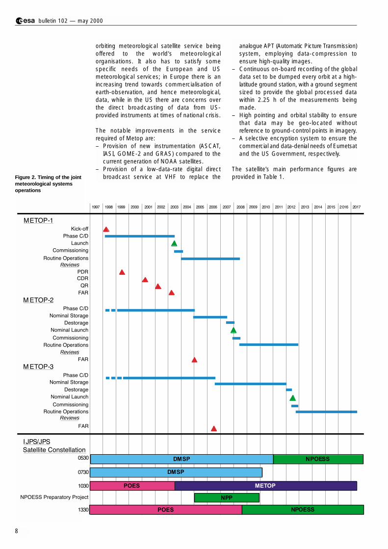
Figure 2. Timing of the jointmeteorological systemsoperations
orbiting meteorological satellite service beingoffered to the world’s meteorologicalorganisations. It also has to satisfy somespecific needs of the European and USmeteorological services; in Europe there is anincreasing trend towards commercialisation ofearth-observation, and hence meteorological,data, while in the US there are concerns overthe direct broadcasting of data from US-provided instruments at times of national crisis.
The notable improvements in the servicerequired of Metop are:– Provision of new instrumentation (ASCAT,
IASI, GOME-2 and GRAS) compared to thecurrent generation of NOAA satellites.
– Provision of a low-data-rate digital directbroadcast service at VHF to replace the
analogue APT (Automatic Picture Transmission)system, employing data-compression toensure high-quality images.
– Continuous on-board recording of the globaldata set to be dumped every orbit at a high-latitude ground station, with a ground segmentsized to provide the global processed datawithin 2.25 h of the measurements beingmade.
– High pointing and orbital stability to ensurethat data may be geo-located withoutreference to ground-control points in imagery.
– A selective encryption system to ensure thecommercial and data-denial needs of Eumetsatand the US Government, respectively.
The satellite’s main performance figures areprovided in Table 1.
r bulletin 102 — may 2000 bull
8
1997 1998 1999 2000 2001 2002 2003 2004 2005 2006 2007 2008 2009 2010 2011 2012 2013 2014 2015 2016
MET
Reviews
METO
Reviews
METOP-3
Reviews
IJPS/JPS
0530
0730
1030
1330
2017
DMSP
DMSP
NPOESS
POES
NPP
METOP
POES NPOESS
Kick-off
Phase C/D
Launch
Commissioning
Routine Operations
PDR
CDR
QR
FAR
OP-1
Phase C/D
Nominal Storage
Destorage
Nominal Launch
Commissioning
Routine Operations
FAR
P-2
Phase C/D
Nominal Storage
Destorage
Nominal Launch
Commissioning
Routine Operations
FAR
Satellite Constellation
NPOESS Preparatory Project

– Microwave Humidity Sounder (MHS), a newinstrument, which will fly on the last of theNOAA satellites, which exactly replaces theAMSU-B currently provided by the UKMeteorological Office to NOAA.
– Space Environment Monitor (SEM), whichmeasures the charged-particle radiationenvironment in the vicinity of the satellite.
– Data Collection System (DCS/Argos), a radioreceiving and storage system, which receivesbrief telemetry signals from a large globalnetwork of remote stations, most of themunmanned and mobile. As well as providingthese messages to a central processing anddistribution site, this new version of thesystem may also send messages to theremote terminals.
– Search and Rescue (S&R), a similar systemwhich immediately rebroadcasts signalsreceived from emergency transmitterstypically carried on vessels and aircraft,enabling rescue services over a wide geo-graphical area to locate the transmitter.
The payload composition of the first threeMetop satellites may be divided into categories.In the first group are instruments providing thetransition from the current NOAA satellites:
– Advanced Very High Resolution Radiometer(AVHRR), an optical/infrared imager with aspatial resolution of about 1 km over a verywide swath of some 2000 km.
– High-resolution Infra-Red Sounder (HIRS),a spectrometer with a relatively coarsespatial resolution and a mechanical scan overa wide swath, from which height profiles ofatmospheric pressure and temperaturemay be derived – this instrument will not beembarked on Metop-3, its measurementfunctions being taken over by IASI, describedbelow.
– Advanced Microwave Sounding Unit A(AMSU-A), a mechanically scanned multi-channel microwave radiometer for thedetermination of pressure and temperatureprofiles.
metop
9
Table 1. Metop main features and performances
Area Performance
Spacecraft orbit: - Sun-synchronous near-circular orbit, altitude at ascending node: 796 to 844 km- Repeat cycle : 5 days (71 orbits)- Local solar time : 09h30 (descending node)
Launch mass: 4174.8 kg
On-board propellant: 315.7 kg of hydrazine, stored in 4 tanks (including residual)
Spacecraft attitude: - Three-axis stabilised through reaction wheels- Orbit manoeuvres through hydrazine propulsion system- Pointing knowledge : 0.07° (X-axis), 0.10° (Y-axis), 0.17° (Z-axis)
Data handling: - Instrument science data acquired as CCSDS packets- Science data formatting and multiplexing, encryption for selected instruments- Instrument and housekeeping data storage in a solid-state recorder (24 Gbit)
Communications: - Omnidirectional S-band coverage (uplink 2 kbps, downlink 4.096 kbps) - Instrument global data stream downlinked via X band (70 Mbps data rate) - Real-time broadcasting of instrument data with HRPT: 3.5 Mbps via L-band for all
instruments, and LRPT: 72 kbps via VHF for selected instruments
On-board power: - 2210 W from solar panel, average power over one orbit (EOL)- Five 40 Ah batteries- 22 - 37.5 V unregulated, and 50 V regulated power lines for SVM/PLM units- 22 - 37 V unregulated power lines for European instruments- 28 V regulated power lines for NOAA instruments
Mission lifetime: 5 years
Launcher: Ariane-5, or Atlas IIAS
Operations: - Spacecraft controlled by Eumetsat (Kiruna ground station)- Instrument X-band data down-linked nominally over 2 ground stations- Recorded data down-linked not later than one orbit after recording- Spacecraft autonomy required for 36 h without ground contact

The second group are from the newgeneration, and offer improved sensingcapabilities:
– Infrared Atmospheric Sounding Interferometer(IASI), is an important new development,which will provide a significant improvementin the resolution of vertical temperature andhumidity profiles in the atmosphere.
– Advanced Scatterometer (ASCAT), developedwithin the framework of the Metop-1contract, which uses multiple radar beamsto measure the small-scale roughness of theocean surface from three directions, over awide swath on each sidenof the satellite,enabling the speed and direction of the windto be determined.
– Global Ozone Measurement Experiment 2
(GOME-2), a successor to the ERS-2 GOME-1with a number of improvements, is a high-resolution visible/ultraviolet spectrometer,which provides measurements over a wideswath and wide spectral range such thatozone profiles and total column amounts ofmany other trace gases may be determined.
– GNSS Receiver for Atmospheric Sounding(GRAS), also developed within the frameworkof the MetOp-1 contract, is a geodetic-qualityGPS receiver equipped with three antennassuch that it is able to measure the signalsfrom GPS satellites in occultation by theEarth’s atmosphere, enabling temperatureand pressure profiles to be determined.
The main performance parameters of theseinstruments are summarised in Table 2.
r bulletin 102 — may 2000 bull
10
Table 2. Instrument performances
Instrument Main Characteristics
AVHRR Six-channel Vis/IR imager (0.6 - 12µm), swath 2000 km, 1 x 1km resolution
HIRS 20-channel Optical/IR filter-wheel radiometer; swath 2000 km; IFOV 17.4 km (nadir)
AMSU- Step-scan 15 channel total power MW A1/A2 radiometers for 50 GHz oxygen absorption line;
swath 2000 km; IFOV 30 km (nadir)
MHS Five-channel quasi-optical heterodyne radiometer, 190 GHz for water-vapour absorption line plus 89 GHz for surface emissivity. Swath 2000 km, IFOV 30 km (nadir)
IASI Fourier-transform spectrometer, 4 IFOV’s of 20 km at nadir in a square 50 x 50 km. Step-scanned across track (30 steps), synchronised to AMSU-A. Integrated (Near-IR) imager for cloud discrimination. Calibration: blackbody plus two deep-space views
ASCAT C-band radar scatterometer, with three dual-swath antennas (fore/mid/aft). Measurement of radar backscatter at three different azimuth angles;fit to a model function to extract wind speed and direction. Incidence angle range: 25° – 65°
GOME-2 Scanning spectrometer with spectral coverage: 250–790 nm at resolution 0.2–0.4 nm. Double monochromator design: first stage: quartz prism with physical separation of four channels; second stage: blazed gratings in each channel. Detector: 1024 pixel random-access silicon-diode arrays;
GRAS GPS satellite receiver measuring changes during occultation (rising or setting); computation of bending angle and TEC; retrieval of refractive index vs altitude profile; fitting data to stratospheric model for temperature profile. Bending angle measurement accuracy better than 1 µrad.
Main Data Products
Wide-swath vertical sounding plus imagerytemperature profile, humidity profile generated byTiros Operational Vertical Sounder (TOVS/ATOVS) combining data from HIRS, AMSU A1/A2 andMHS, supported by AVHRR Secondary Products:sea-surface temperature, cloud fraction/cloud topheight, aerosol, precipitable water, surfaceemission, total ozone, sea-ice extent
Water-vapour sounding; NO2 and CO2 ;temperature sounding; surface and cloudproperties. Swath width: 2000 km Performance: spectral range: 3.62-15.5 µm in 3 bands; resolution 0.35 cm-1; radiometricaccuracy 0.25 - 0.58 K
Surface-wind vectors over oceans; additionalproducts (e.g. sea-ice cover; snow cover;vegetation density). Swath width: 2 x 500 km;Quasi-global coverage: 2.5 d.Wind velocity:± 2ms-1 or 10%; Wind direction: ± 20°
Ozone (total column and profiles, stratosphereand troposphere); NO2 BrO OClO ClO;Albedo and aerosol: cloud fraction, cloud-topaltitude, cloud phase.Swath width: 960 or 1920 km, resolution 80 x 40or 160 x 40 km
Up to 500 occultations/day, with quasi-uniformgeographical distribution Vertical temperature sounding of ±1 K, withvertical resolution of 150 m in the troposphere (5 - 30 km) and 1.5 km in the stratosphere
Heritage Notes
TIROS/POES
TIROS/POES Disembarkedfor METOP-3
TIROS/POES
TIROS/POES As AMSU-B
New Replaces and development supplements
HIRS
ERS-1/-2AMI-Scatterometer
ERS-2GOME-1
GPS/MET

11
– NOAA: Funds US instruments for Metop;System authority for POES as part of IJPS.
– NASA: Develops/procures AVHRR, HIRS,AMSU and SEM for Metop.
– CNES: Co-funds and develops IASI; Fundsand develops DCS, SARP.
A special relationship has been developedbetween ESA and Eumetsat, governed by a
Aspects of cooperationThe EPS and the Metop Programme areintensively collaborative in that five majoragencies are extensively involved:– Eumetsat: System authority, develops
Ground Segment and MHS, co-funds Metopand IASI, procures launcher, operates system.
– ESA: Co-funds and develops Metop, ASCAT,GOME-2 and GRAS.
metop
Figure 4. Cooperationbetween ESA and Eumetsat
Figure 3. Cooperation onMetop

legal act, the Cooperation Agreement, signedin December 1999. In this cooperation, a co-funding arrangement is established for theMetop industrial contracts, which is managedby a joint project team called the ‘Single SpaceSegment Team (or SSST)’, comprised of stafffrom both organisations and located at ESTEC.The team has an ESA project manager assistedby a Eumetsat deputy. The respectiveresponsibilities are shown in Figures 3 and 4.
Industrial architectureThe Prime Contractor for Metop is MatraMarconi Space France (MMS-F). The contractincludes the three Metop spacecraft and theASCAT and GRAS payload instruments. Aseparate contract within the Metop Programmehas been placed with Officine Galileo/AleniaDifesa for the three GOME-2 instruments. Allother payload instruments are provided to theMetop Programme as customer-furnishedinstruments via Eumetsat.
MMS-F is responsible for the execution of alltasks performed by the industrial team,including system-level tasks and satelliteassembly, integration and testing, and for theService Module (SVM) with its Electrical GroundSupport Equipment (EGSE).
Among the various contractors involved,– Dornier Satellitensysteme (DSS)* is responsible
for the Payload Module, ASCAT, and GRAS(with Saab-Ericsson)
– MMS-UK** is responsible for the ServiceModule mechanical system, and system-support tasks
– Alenia is responsible for DCS/Search & Rescuemission integration and accommodationhardware.
Subcontractors, at unit or subsystem level,have been selected on the basis of heritage, orafter competition. Figure 5 shows the currentindustrial team.
r bulletin 102 — may 2000 bull
12
Figure 5. The Metop industrial organisation
* Now Astrium GmbH**Now Astrium Ltd.

developed within the same broad time-frameas Metop-1, but it is intended to be a directreplacement for the AMSU-B and, furthermore,it will fly before Metop on at least one USsatellite.
The ASCAT depends on the same physicalprinciple as the scatterometers on ERS-1 andERS-2, and the higher level processing of thedata is equivalent. Hence it may be rapidlyadopted as an operational instrument, as theERS-2 instrument is today. However, it has twoswaths compared to the one of ERS and alsouses a different radar technique, such that thedata pre-processing needs to be newlydeveloped. The GOME-2 is also stronglyrelated to the equivalent instrument on ERS-2,again leading to many advantages in terms ofprocurement, development of operational dataprocessors, and existing user-experience in thedata exploitation.
Context of the missionThe Metop satellite and its payload embody agreat deal of heritage, which has two primarybenefits. The heritage of the satellite (especiallythe SVM) and its equipment have enabledsignificant cost savings in the developmentprogramme, while the heritage of the payloadand services is an essential element in theefficient exploitation of the mission data. Almostall payload elements have direct andoperational precursors, the only exceptionbeing the GRAS instrument, and even this isthe operational follow-on to an in-orbitexperiment. The transitional instruments in thefirst group above, commonly called the ATOVSpackage, supplemented by the DCS/S+R andSEM, are directly recurrent from the USsatellites and have a strong heritage both interms of hardware provision as well as in theprocessing and exploitation of the data.Amongst these, the MHS instrument is being
metop
13
Figure 6. The Service Module’s heritage

Figure 7. Metop’s in-flightconfiguration
MMS has more than twenty years ofexperience in the development of low-Earth-orbit service modules which is of direct benefitfor Metop. Regular upgrades to the Spot-1concept have been performed to meet higherperformance requirements and to maintain up-to-date avionics and technologies. Acumulated 46 year lifetime in orbit has beenachieved today with 8 satellites (ERS-1 and 2,Spot-1, 2, 3 and 4, and Helios-1A and 1B)using the same SVM concept (Fig. 6). TheSpot-1 SVM completed its 14th year ofoperation last year. ERS-1 operated verysuccessfully for almost 9 years.
Overall architecture of the satelliteIn order to accommodate the mission, and toease the development as well as the verificationprocess, the satellite’s overall design is basedon a modular approach, which relies upon twolargely independent modules, the PayloadModule and the Service Module. Figure 7 showsthe Metop in-flight configuration.
The Payload Module (PLM)The PLM provides the main supportingstructure for both the payload instruments andthe payload support systems. Instrumentsensors and antennas are mounted on the
r bulletin 102 — may 2000 bull
14
two modules have been standardised as muchas possible, and kept to a minimum. Thermalexchanges between the two modules are verylimited, mechanical interfaces basically consistof the two modules connection, electricalinterfaces are limited to power and OBDH bus,plus solar-array deployment and pyrotechnicsneeds, data exchanges use telemetry andtelecomand packets.
The satellite overall dimensions (in metres) areclose to 6.3 (high) by 3.4 x 3.4 (transversesection) in launch configuration, and 17.6 x 6.6x 5.0, after solar-array and antenna deployment.
Electrical architectureModularity and standardisation are the maindesign drivers for the electrical architecture(Fig. 8). The design offers simple interfaces, andmakes use of existing hardware developed inthe frames of Spot-5 for the SVM and Envisatfor the PLM.
Power generation, storage and distributionElectrical power is generated by an eight-panelsolar array derived from Envisat. Energystorage is provided by five batteries, whichallow operation in the launch and early orbitphase (LEOP), eclipse and contingency modes.The primary power bus is an unregulated bus,which is distributed to both the SVM and PLMunits. The 28 V power regulation needed by theUS instruments is performed by a dedicatedPLM unit (PCU).
Command and controlThe command and control functions aredistributed throughout the spacecraft, and alsohave to accommodate a range of interfacerequirements from the heritage instruments.The Metop-specific equipment and instrumentsuse the European OBDH interfaces, while theMHS uses the MIL-STD-1553 interface. Both ofthese are high-level command and controlinterfaces allowing for intelligence within theinstruments. The heritage instruments fromNOAA have a much simpler interface withdistributed signal lines.
The distributed command and controlarchitecture features the following elements:
– The primary spacecraft computer is withinthe SVM and is responsible for the interfaceto the ground segment and control of theequipment in the SVM and for the overallsecurity of the mission.
– Command and control of the payload isperformed by the PLM Computer (PMC),which is connected to the SVM computer viathe SVM OBDH bus. This computer controlsa specific OBDH bus within the PLM.
external panels, while most of the electronicsunits are accommodated inside the PLM.
The accommodation of a large complement ofinstruments is a significant design driver for the overall PLM configuration, with manyconstraints originating from instrument fields ofview, antenna patterns, and thermal radiatorshaving to be accounted for. In addition to theinstrument units, the PLM also houses all of theavionics necessary to ensure:
– power regulation for the US instruments: asthese instruments need a 28 V regulatedpower bus not available from the SVM; adedicated power control unit is provided bythe PLM
– power distribution: each unit or instrument ispowered through a switchable and protectedline, provided by specific PLM units
– command and control: a dedicated data bus,based on the European On-Board DataHandling Standard (OBDH), is used by thePLM. The Payload Module Computer (PMC)receives commands from the SVM andinterfaces with the European instrumentsICUs (Instrument Control Units) and MPU(MHS PLM adaptation Unit), as well as with aspecific PLM unit for the US instruments
– handling of scientific data consisting ofacquisition, formatting, encryption, storage,and transmission to ground of CCDSpacketised data through the HRPT (High-Rate Picture Transmission), LRPT (Low-RatePicture Transmission), and X-band links.
The Service Module (SVM)The SVM provides all the standard servicefunctions, like:– attitude and orbit control, to maintain
accurate Earth-pointing during the variousoperational modes, and to perform orbitacquisition and maintenance
– propulsion, for orbit and dedicated manoeuvres,as well as propellant storage
– electrical power generation, through the solararray, storage, conditioning, and overalldistribution
– distribution of on-ground and on-boardgenerated commands, and collection of house-keeping telemetry data for transmission toground through the S-band link
– central on-board software for telemetrygeneration, telecommand processing, andvarious application functions (e.g. thermalcontrol, on-board surveillance, automaticcommand sequencing).
The mechanical subsystem is derived from theEnvisat Service Module. It is a box-shapedstructure that interfaces with both the launchvehicle and the PLM. Interfaces between the
metop
15

Figure 8. Metop’s electricalarchitecture
– The ‘European’ instruments (ASCAT, GRAS,GOME, IASI) each include an intelligentInstrument Control Unit (ICU) whichcommunicates with the PMC.
– The MHS communicates via a specificadaptation unit, MPU, or MHS Protocol Unit,which performs the translation between theMHS MIL-STD 1553 bus and the PLMOBDH. The MPU also provides the science-data interface.
– The NOAA Interface Unit (NIU) emulates theTiros-spacecraft-type interfaces required bythe NOAA instruments. It includes its ownICU, which performs the command andcontrol function as well as packaging theNOAA instrument data into CCSDS packets. It also performs the AVHRR datacompression.
Payload data handling and transmissionThe science data from the payload is providedin the form of CCSDS packets at a wide rangeof data rates, ranging from 1.5 Mbps for IASI to160 bps for SEM. The PMC also providessome additional packets required for dataexploitation:
– Position and time data derived from theGRAS.
– A copy of the full spacecraft housekeepingtelemetry.
– A text ‘administration message’ which isuplinked and stored on board, providing thefacility to broadcast information to remoteusers.
All of these data streams are multiplexed andprovided on three channels going to the on-board recorder, the HRPT, and LRPT direct-broadcast subsystems. Encryption is possiblefor the direct-broadcast services. Only a subsetof the packets is provided to the LRPT.
The Solid-State Recorder is based on theCluster and Envisat design, and has a capacityof 24 GB at end-of-life. This is sufficient forslightly more than one full orbit of data.The X-band subsystem provides a direct 70 Mbpstransmission link to ground during visibilityperiods, dumping the data stored during theprevious orbit to ground.
Telemetry, tracking and commandTwo antennas allowing omni-directional coverageinterface with the S-band transponder bymeans of a 3 dB hybrid coupler. Eachtransponder consists of a diplexer, a receiverand a transmitter.
Attitude and orbit controlThe AOCS architecture is based around threeunits performing the interface between theSVM OBDH bus and the sensors andactuators. A first unit (T4S) interfaces with theEarth and Sun sensors, and with the gyros; theEAIM provides the interface with the reactionwheels and the magnetotorquers; the EPRMensures the necessary command and acquisitioncapability for the propulsion subsystem, andalso interfaces with the solar-array drivemechanism.
r bulletin 102 — may 2000 bull
16
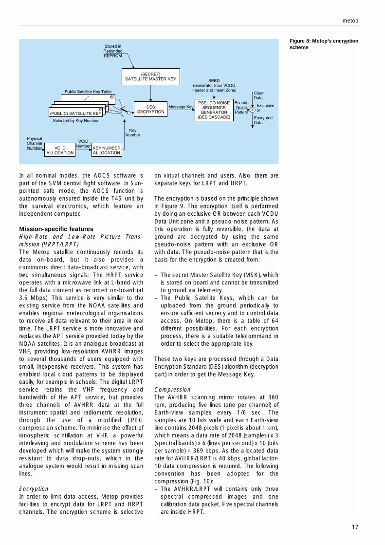
Figure 8: Metop’s encryptionscheme
on virtual channels and users. Also, there areseparate keys for LRPT and HRPT.
The encryption is based on the principle shownin Figure 9. The encryption itself is performedby doing an exclusive OR between each VCDUData Unit zone and a pseudo-noise pattern. Asthis operation is fully reversible, the data atground are decrypted by using the samepseudo-noise pattern with an exclusive ORwith data. The pseudo-noise pattern that is thebasis for the encryption is created from:
– The secret Master Satellite Key (MSK), whichis stored on board and cannot be transmittedto ground via telemetry.
– The Public Satellite Keys, which can beuploaded from the ground periodically toensure sufficient secrecy and to control dataaccess. On Metop, there is a table of 64different possibilities. For each encryptionprocess, there is a suitable telecommand inorder to select the appropriate key.
These two keys are processed through a DataEncryption Standard (DES) algorithm (decryptionpart) in order to get the Message Key.
CompressionThe AVHRR scanning mirror rotates at 360rpm, producing five lines (one per channel) ofEarth-view samples every 1/6 sec. Thesamples are 10 bits wide and each Earth-viewline contains 2048 pixels (1 pixel is about 1 km),which means a data rate of 2048 (samples) x 3(spectral bands) x 6 (lines per second) x 10 (bitsper sample) = 369 kbps. As the allocated datarate for AVHRR/LRPT is 40 kbps, global factor-10 data compression is required. The followingconvention has been adopted for thecompression (Fig. 10):– The AVHRR/LRPT will contains only three
spectral compressed images and onecalibration data packet. Five spectral channelsare inside HRPT.
In all nominal modes, the AOCS software ispart of the SVM central flight software. In Sun-pointed safe mode, the AOCS function isautonomously ensured inside the T4S unit bythe survival electronics, which feature anindependent computer.
Mission-specific featuresHigh-Rate and Low-Rate Picture Trans-mission (HRPT/LRPT)The Metop satellite continuously records itsdata on-board, but it also provides acontinuous direct data-broadcast service, withtwo simultaneous signals. The HRPT serviceoperates with a microwave link at L-band withthe full data content as recorded on-board (at3.5 Mbps). This service is very similar to theexisting service from the NOAA satellites andenables regional meteorological organisationsto receive all data relevant to their area in realtime. The LRPT service is more innovative andreplaces the APT service provided today by theNOAA satellites. It is an analogue broadcast atVHF, providing low-resolution AVHRR imagesto several thousands of users equipped withsmall, inexpensive receivers. This system hasenabled local cloud patterns to be displayedeasily, for example in schools. The digital LRPTservice retains the VHF frequency andbandwidth of the APT service, but providesthree channels of AVHRR data at the fullinstrument spatial and radiometric resolution,through the use of a modified JPEGcompression scheme. To minimise the effect ofionospheric scintillation at VHF, a powerfulinterleaving and modulation scheme has beendeveloped which will make the system stronglyresistant to data drop-outs, which in theanalogue system would result in missing scanlines.
EncryptionIn order to limit data access, Metop providesfacilities to encrypt data for LRPT and HRPTchannels. The encryption scheme is selective
metop
17

– The compression is applied to the 10-bitdata sample words.
– The compression algorithm is a modifiedJPEG to accommodate a fixed compressionrate and a continuous instrument data rate.
An AVHRR image can be divided into strips (8 lines). The compressed part of the strip will betransmitted in the user data field of one CCSDSpacket. The strips are divided into segments.Inside a segment, a constant Q factor isapplied. Finally, each segment is divided intoblocks of 8 pixels x 8 lines. A compressed blockis called a Minimum Coded Unit (MCU). Therewill be four packets (three channels and onecalibration) every 8/6 seconds (1 strip lasts 8/6sec). The global number of MCUs is 2048/8 =256. The number of segments can beprogrammed from the ground, albeit with apotential impact on image quality since aconstant Q factor is applied on one segment.
Communications linksThe satellite provides data transmission to andfrom the ground with the characteristicsdefined in Table 3, and as described previously,in S-band (TT&C), L-band (HRPT), VHF (LRPT)
and X-band (global data dump). In addition tothese links, Metop provides an Advanced DCS(Argos) service and a Search & Rescue (SARR/SARP) service with the following frequencies:
– A-DCS data reception at 401.65 MHz– A-DCS data transmission at 466 MHz– SARR beacon-signal reception at 121.5,
243 and 406.05 MHz– SARP-2 data reception at 406.05 MHz
(common with SARR)– SARR data transmission at 1544.5 GHz.
These links are performed by means of anantenna farm comprised of the followingelements:
– X-band transmit antenna– S-band TT&C receive/transmit antenna– LRPT VHF transmit antenna– HRPT L-band transmit antenna– CRA: Combined Receive Antenna (uplink)– SLA: Search and Rescue L-band transmit
antenna– DTA: DCS transmit antenna.
One major consequence of these variousspace-to-ground links, combined withnumerous RF instruments (AMSU A1, AMSUA2, MHS, GRAS, ASCAT), is the fact thatensuring RF compatibility within the satellite is achallenging design requirement leading to an extensive test campaign and a dedicateddevelopment approach. r
r bulletin 102 — may 2000 bull
18
Table 3. Metop’s data interface with ground
Data Description Frequency Domain Useful Bit Rate
TT&C uplink S-band 2053.4 MHz 2000 bps in NRZ/PSK/PM
TT&C downlink S band 2230 MHz 4096 bps in SP-L/PSK/PM
Global Data Stream X-band 7750-7900 MHz 70 Mbps in QPSKdownlink
LRPT downlink VHF 137.1 MHz 72 kbps in QPSK
HRPT downlink L-band 1701.3 MHz 3.5 Mbps in QPSK
1 segment = 1 area withconstant Q factor
1 MCU = 1 block compressed data
1 CCSDS packet : 256 MCU
(1 MCU = 9 km x 9 km compressed data)
Compression
hdr 1 strip compressed data
scanhdr seg 1 seg n
MCU mMCU 1seg hdr
Compression
line n
line n+7
2048 pixels
8 pixels x 8 lines = 1 block
1 strip8/6 sec
1 AVHRR strip (per channel)
2200 km x 9 km
Figure 10. Metop’scompression scheme:
AVHRR data