method to-17 - determination of volatile organic compounds
TRANSCRIPT

EPA/625/R-96/010b
Compendium of Methods for the Determination of Toxic
Organic Compounds in Ambient Air
Second Edition
Compendium Method TO-17
Determination of Volatile Organic Compounds in Ambient Air Using Active
Sampling Onto Sorbent Tubes
Center for Environmental Research Information Office of Research and Development
U.S. Environmental Protection Agency Cincinnati, OH 45268
January 1999

Method TO-17 Acknowledgements
This Method was prepared for publication in the Compendium of Methods for the Determination of Toxic Organic Compounds in Ambient Air, Second Edition (EPA/625/R-96/010b), which was prepared under Contract No. 68-C3-0315, WA No. 3-10, by Midwest Research Institute (MRI), as a subcontractor to Eastern Research Group, Inc. (ERG), and under the sponsorship of the U. S. Environmental Protection Agency (EPA). Justice A. Manning, John O. Burckle, and Scott Hedges, Center for Environmental Research Information (CERI), and Frank F. McElroy, National Exposure Research Laboratory (NERL), all in the EPA Office of Research and Development, were responsible for overseeing the preparation of this method. Additional support was provided by other members of the Compendia Workgroup, which include:
• John O. Burckle, U.S. EPA, ORD, Cincinnati, OH • James L. Cheney, Corps of Engineers, Omaha, NB • Michael Davis, U.S. EPA, Region 7, KC, KS • Joseph B. Elkins Jr., U.S. EPA, OAQPS, RTP, NC • Robert G. Lewis, U.S. EPA, NERL, RTP, NC • Justice A. Manning, U.S. EPA, ORD, Cincinnati, OH • William A. McClenny, U.S. EPA, NERL, RTP, NC • Frank F. McElroy, U.S. EPA, NERL, RTP, NC • Heidi Schultz, ERG, Lexington, MA • William T. "Jerry" Winberry, Jr., EnviroTech Solutions, Cary, NC
This Method is the result of the efforts of many individuals. Gratitude goes to each person involved in the preparation and review of this methodology.
Author(s) • Elizabeth A. Woolfenden, Perkin Elmer Corp., Wilton, CT • William A. McClenny, U.S. EPA, NERL, RTP, NC
Peer Reviewers • Joan T. Bursey, ERG, Morrisville, NC • Martin Harper, SKC Inc., Eighty-Four, PA • Irene D. DeGraff, Supelco, Inc., Bellefonte, PA • Joseph E. Bumgarner, U. S. EPA, NERL, RTP, NC • Lauren Drees, U.S. EPA, NRMRL, Cincinnati, OH
Finally, recognition is given to Frances Beyer, Lynn Kaufman, Debbie Bond, Cathy Whitaker, and Kathy Johnson of Midwest Research Institute's Administrative Services staff whose dedication and persistence during the development of this manuscript has enabled it's production.
DISCLAIMER
This Compendium has been subjected to the Agency's peer and administrative review, and it has been approved for publication as an EPA document. Mention of trade names or commercial products does not constitute endorsement or recommendation for use.
ii
METHOD TO-17
Determination of Volatile Organic Compounds in Ambient Air Using Active Sampling Onto Sorbent Tubes
TABLE OF CONTENTS
Page
1. Scope . . . . . . . . . . . . . . . . . . . . . . . . . . . . . . . . . . . . . . . . . . . . . . . . . . . . . . . . . . . . . . . . . . . . . . 17-1
2. Summary of Method . . . . . . . . . . . . . . . . . . . . . . . . . . . . . . . . . . . . . . . . . . . . . . . . . . . . . . . . . . 17-2
3. Significance . . . . . . . . . . . . . . . . . . . . . . . . . . . . . . . . . . . . . . . . . . . . . . . . . . . . . . . . . . . . . . . . . 17-3
4. Applicable Documents . . . . . . . . . . . . . . . . . . . . . . . . . . . . . . . . . . . . . . . . . . . . . . . . . . . . . . . . . 17-4 4.1 ASTM Standards . . . . . . . . . . . . . . . . . . . . . . . . . . . . . . . . . . . . . . . . . . . . . . . . . . . . . . . . . . 17-4 4.2 EPA Documents . . . . . . . . . . . . . . . . . . . . . . . . . . . . . . . . . . . . . . . . . . . . . . . . . . . . . . . . . . . 17-4 4.3 Other Documents . . . . . . . . . . . . . . . . . . . . . . . . . . . . . . . . . . . . . . . . . . . . . . . . . . . . . . . . . . 17-4
5. Definitions . . . . . . . . . . . . . . . . . . . . . . . . . . . . . . . . . . . . . . . . . . . . . . . . . . . . . . . . . . . . . . . . . . 17-5
6. Overview of Methodology . . . . . . . . . . . . . . . . . . . . . . . . . . . . . . . . . . . . . . . . . . . . . . . . . . . . . . 17-6 6.1 Selection of Tube and Sorbent . . . . . . . . . . . . . . . . . . . . . . . . . . . . . . . . . . . . . . . . . . . . . . . . 17-7 6.2 Conditioning the Tube . . . . . . . . . . . . . . . . . . . . . . . . . . . . . . . . . . . . . . . . . . . . . . . . . . . . . . 17-7 6.3 Sampling Apparatus . . . . . . . . . . . . . . . . . . . . . . . . . . . . . . . . . . . . . . . . . . . . . . . . . . . . . . . 17-7 6.4 Sampling Rates . . . . . . . . . . . . . . . . . . . . . . . . . . . . . . . . . . . . . . . . . . . . . . . . . . . . . . . . . . . 17-7 6.5 Preparing for Sample Collection . . . . . . . . . . . . . . . . . . . . . . . . . . . . . . . . . . . . . . . . . . . . . . 17-8 6.6 Set the Flow Rates . . . . . . . . . . . . . . . . . . . . . . . . . . . . . . . . . . . . . . . . . . . . . . . . . . . . . . . . . 17-8 6.7 Sample and Recheck Flow Rates . . . . . . . . . . . . . . . . . . . . . . . . . . . . . . . . . . . . . . . . . . . . . . 17-8 6.8 Reseal the Tubes . . . . . . . . . . . . . . . . . . . . . . . . . . . . . . . . . . . . . . . . . . . . . . . . . . . . . . . . . . 17-8 6.9 Selection of Thermal Desorption System . . . . . . . . . . . . . . . . . . . . . . . . . . . . . . . . . . . . . . . 17-8 6.10 Dry Purge the Tubes and Prepare for Thermal Desorption . . . . . . . . . . . . . . . . . . . . . . 17-9 6.11 Check for System Integrity . . . . . . . . . . . . . . . . . . . . . . . . . . . . . . . . . . . . . . . . . . . . . . . 17-9 6.12 Repurge of Tube on the Thermal Desorber/Addition of Internal Standard . . . . . . . . . . 17-9 6.13 Thermally Desorb the Packing . . . . . . . . . . . . . . . . . . . . . . . . . . . . . . . . . . . . . . . . . . . . 17-9 6.14 Trap Desorption and GC/MS Analysis . . . . . . . . . . . . . . . . . . . . . . . . . . . . . . . . . . . . . . 17-9 6.15 Restoring the Tubes and Determine Compliance with Performance Standards . . . . . . . 17-9 6.16 Record and Store Data . . . . . . . . . . . . . . . . . . . . . . . . . . . . . . . . . . . . . . . . . . . . . . . . . . . 17-10
7. Interferences and Limitations . . . . . . . . . . . . . . . . . . . . . . . . . . . . . . . . . . . . . . . . . . . . . . . . . . . . 17-10 7.1 Interference from Sorbent Artifacts . . . . . . . . . . . . . . . . . . . . . . . . . . . . . . . . . . . . . . . . . . . . 17-10 7.2 Minimizing Interference from Water . . . . . . . . . . . . . . . . . . . . . . . . . . . . . . . . . . . . . . . . . . . 17-11 7.3 Atmospheric Pollutants not Suitable for Analysis by this Method . . . . . . . . . . . . . . . . . . . . 17-12 7.4 Detection Limits and Maximum Quantifiable Concentrations of Air Pollutants . . . . . . . . . 17-12 7.5 Suitable Atmospheric Conditions . . . . . . . . . . . . . . . . . . . . . . . . . . . . . . . . . . . . . . . . . . . . . 17-12
iii

TABLE OF CONTENTS (continued)
Page
8. Apparatus Selection and Preparation . . . . . . . . . . . . . . . . . . . . . . . . . . . . . . . . . . . . . . . . . . . . . . 17-13 8.1 Sample Collection . . . . . . . . . . . . . . . . . . . . . . . . . . . . . . . . . . . . . . . . . . . . . . . . . . . . . . . . . 17-13 8.2 Apparatus . . . . . . . . . . . . . . . . . . . . . . . . . . . . . . . . . . . . . . . . . . . . . . . . . . . . . . . . . . . . . . . . 17-14 8.3 Tube Conditioning Apparatus . . . . . . . . . . . . . . . . . . . . . . . . . . . . . . . . . . . . . . . . . . . . . . . . 17-15
9. Reagents and Materials . . . . . . . . . . . . . . . . . . . . . . . . . . . . . . . . . . . . . . . . . . . . . . . . . . . . . . . . 17-16 9.1 Sorbent Selection Guidelines . . . . . . . . . . . . . . . . . . . . . . . . . . . . . . . . . . . . . . . . . . . . . . . . . 17-16 9.2 Gas Phase Standards . . . . . . . . . . . . . . . . . . . . . . . . . . . . . . . . . . . . . . . . . . . . . . . . . . . . . . . 17-17 9.3 Liquid Standards . . . . . . . . . . . . . . . . . . . . . . . . . . . . . . . . . . . . . . . . . . . . . . . . . . . . . . . . . . 17-17 9.4 Gas Phase Internal Standards . . . . . . . . . . . . . . . . . . . . . . . . . . . . . . . . . . . . . . . . . . . . . . . . 17-19 9.5 Commercial, Preloaded Standard Tubes . . . . . . . . . . . . . . . . . . . . . . . . . . . . . . . . . . . . . . . . 17-19 9.6 Carrier Gases . . . . . . . . . . . . . . . . . . . . . . . . . . . . . . . . . . . . . . . . . . . . . . . . . . . . . . . . . . . . . 17-19
10. Guidance on Sampling and Related Procedures . . . . . . . . . . . . . . . . . . . . . . . . . . . . . . . . . . . . . 17-20 10.1 Packing Sorbent Tubes . . . . . . . . . . . . . . . . . . . . . . . . . . . . . . . . . . . . . . . . . . . . . . . . . . 17-20 10.2 Conditioning and Storage of Blank Sorbent Tubes . . . . . . . . . . . . . . . . . . . . . . . . . . . . 17-21 10.3 Record Keeping Procedures for Sorbent Tubes . . . . . . . . . . . . . . . . . . . . . . . . . . . . . . . 17-21 10.4 Pump Calibration and Tube Connection . . . . . . . . . . . . . . . . . . . . . . . . . . . . . . . . . . . . . 17-22 10.5 Locating and Protecting the Sample Tube . . . . . . . . . . . . . . . . . . . . . . . . . . . . . . . . . . . 17-22 10.6 Selection of Pump Flow Rates and Air Sample Volumes . . . . . . . . . . . . . . . . . . . . . . . . 17-22 10.7 Sampling Procedure Verification - Use of Blanks, Distributed Volume Pairs,
BackUp Tubes, and Distributed Volume Sets . . . . . . . . . . . . . . . . . . . . . . . . . . . . . . . . 17-23 10.8 Determining and Validating Safe Sampling Volumes (SSV) . . . . . . . . . . . . . . . . . . . . . 17-24 10.9 Resealing Sorbent Tubes After Sample Collection . . . . . . . . . . . . . . . . . . . . . . . . . . . . . 17-25 10.10 Sample Storage . . . . . . . . . . . . . . . . . . . . . . . . . . . . . . . . . . . . . . . . . . . . . . . . . . . . . . . . 17-25
11. Analytical Procedure . . . . . . . . . . . . . . . . . . . . . . . . . . . . . . . . . . . . . . . . . . . . . . . . . . . . . . . . . . 17-25 11.1 Preparation for Sample Analysis . . . . . . . . . . . . . . . . . . . . . . . . . . . . . . . . . . . . . . . . . . . 17-25 11.2 Predesorption System Checks and Procedures . . . . . . . . . . . . . . . . . . . . . . . . . . . . . . . . 17-25 11.3 Analytical Procedure . . . . . . . . . . . . . . . . . . . . . . . . . . . . . . . . . . . . . . . . . . . . . . . . . . . . 17-26
12. Calibration of Response . . . . . . . . . . . . . . . . . . . . . . . . . . . . . . . . . . . . . . . . . . . . . . . . . . . . . . . . 17-27
13. Quality Assurance . . . . . . . . . . . . . . . . . . . . . . . . . . . . . . . . . . . . . . . . . . . . . . . . . . . . . . . . . . . . 17-27 13.1 Validating the Sample Collection Procedure . . . . . . . . . . . . . . . . . . . . . . . . . . . . . . . . . . 17-27 13.2 Performance Criteria for the Monitoring Pump . . . . . . . . . . . . . . . . . . . . . . . . . . . . . . . 17-28
14. Performance Criteria for the Solid Adsorbent Sampling of Ambient Air . . . . . . . . . . . . . . . . . . 17-28 14.1 Introduction . . . . . . . . . . . . . . . . . . . . . . . . . . . . . . . . . . . . . . . . . . . . . . . . . . . . . . . . . . . 17-28 14.2 Method Detection Limit . . . . . . . . . . . . . . . . . . . . . . . . . . . . . . . . . . . . . . . . . . . . . . . . . 17-28 14.3 Analytical Precision of Duplicate Pairs . . . . . . . . . . . . . . . . . . . . . . . . . . . . . . . . . . . . . . 17-29 14.4 Precision for the Distributed Volume Pair . . . . . . . . . . . . . . . . . . . . . . . . . . . . . . . . . . . 17-29 14.5 Audit Accuracy . . . . . . . . . . . . . . . . . . . . . . . . . . . . . . . . . . . . . . . . . . . . . . . . . . . . . . . . 17-29
15. References . . . . . . . . . . . . . . . . . . . . . . . . . . . . . . . . . . . . . . . . . . . . . . . . . . . . . . . . . . . . . . . . . . 17-30
iv
METHOD TO-17
Determination of Volatile Organic Compounds in Ambient Air Using Active Sampling Onto Sorbent Tubes
1. Scope
1.1 This document describes a sorbent tube/thermal desorption/gas chromatographic-based monitoring method for volatile organic compounds (VOCs) in ambient air at 0.5 to 25 parts per billion (ppbv) concentration levels. Performance criteria are provided as part of the method in Section 14. EPA has previously published Compendium Method TO-1 describing the use of the porous polymer Tenax® GC for sampling nonpolar VOCs and Compendium Method TO-2 describing the use of carbon molecular sieve for highly volatile, nonpolar organics (1). Since these methods were developed, a new generation of thermal desorption systems as well as new types of solid adsorbents have become available commercially. These sorbents are used singly or in multisorbent packings. Tubes with more than one sorbent, packed in order of increasing sorbent strength are used to facilitate quantitative retention and desorption of VOCs over a wide volatility range. The higher molecular weight compounds are retained on the front, least retentive sorbent; the more volatile compounds are retained farther into the packing on a stronger adsorbent. The higher molecular weight compounds never encounter the stronger adsorbents, thereby improving the efficiency of the thermal desorption process.
1.2 A large amount of data on solid adsorbents is available through the efforts of the Health and Safety Laboratory, Health and Safety Executive (HSE), Sheffield, United Kingdon (UK). This group has provided written methods for use of solid adsorbent packings in monitoring workplace air. Some of their documents on the subject are referenced in Section 2.2. Also, a table of information on safe sampling volumes from their research is provided in Appendix 1.
1.3 EPA has developed data on the use of solid sorbents in multisorbent tubes for concentration of VOCs from the ambient air as part of its program for methods development of automated gas chromatographs. The experiments required to validate the use of these sorbent traps include capture and release efficiency studies for given sampling volumes. These studies establish the validity of using solid adsorbents for target sets of VOCs with minimal (at most one hour) storage time. Although questions related to handling, transport and storage of samples between the times of sampling and analysis are not addressed, these studies provide information on safe sampling volumes. Appendix 2 delineates the results of sampling a mixture of humidified zero air and the target VOCs specified in the Compendium Method TO-14 (2) using a specific multisorbent.
1.4 An EPA workshop was convened in November of 1995 to determine if a consensus could be reached on the use of solid sorbent tubes for ambient air analysis. The draft method available at the workshop has evolved through several reviews and modifications into the current document. The method is supported by data reported in the scientific literature as cited in the text, and by recent experimental tests performed as a consequence of the workshop (see Table 1).
1.5 The analytical approach using gas chromatography/mass spectroscopy (GC/MS) is identical to that mentioned in Compendium Method TO-15 and, as noted later, is adapted for this method once the sample has been thermally desorbed from the adsorption tube onto the focusing trap of the analytical system.
January 1999 Compendium of Methods for Toxic Organic Air Pollutants Page 17-1
Method TO-17 VOCs
1.6 Performance criteria are given in Section 14 to allow acceptance of data obtained with any of the many variations of sampling and analytical approaches.
2. Summary of Method
2.1 The monitoring procedure involves pulling a volume of air through a sorbent packing to collect VOCs followed by a thermal desorption-capillary GC/MS analytical procedure.
2.2 Conventional detectors are considered alternatives for analysis subject to the performance criteria listed in Section 14 but are not covered specifically in this method text.
2.3 Key steps of this method are listed below.
2.3.1 Selection of a sorbent or sorbent mix tailored for a target compound list, data quality objectives and sampling environment.
2.3.2 Screening the sampling location for VOCs by taking single tube samples to allow estimates of the nature and amount of sample gases.
2.3.3 Initial sampling sequences with two tubes at nominally 1 and 4 liter total sample volumes (or appropriate proportional scaling of these volumes to fit the target list and monitoring objectives).
2.3.4 Analysis of the samples and comparison to performance criteria. 2.3.5 Acceptance or rejection of the data. 2.3.6 If rejection, then review of the experimental arrangement including repeat analysis or repeat analysis
with backup tubes and/or other QC features.
[Note: EPA requires the use of distributed volume pairs (see Section14.4) for monitoring to insure high quality data. However, in situations where acceptable data have been routinely obtained through use of distributed volume pairs and the ambient air is considered well characterized, cost considerations may warrant single tube sampling. Any attendant risk to data quality objectives is the responsibility of the project’s decision maker.]
2.4 Key steps in sample analysis are listed below.
2.4.1 Dry purge of the sorbent tube with dry, inert gas before analysis to remove water vapor and air. The sorbent tube can be held at temperatures above ambient for the dry purge.
2.4.2 Thermal desorption of the sorbent tube (primary desorption). 2.4.3 Analyte refocusing on a secondary trap. 2.4.4 Rapid desorption of the trap and injection/transfer of target analytes into the gas chromatograph
(secondary desorption). 2.4.5 Separation of compounds by high resolution capillary gas chromatography (GC). 2.4.6 Measurement by mass spectrometry (MS) or conventional GC detectors (only the MS approach is
explicitly referred to in Compendium Method TO-17; an FID/ECD detector combination or other GC detector can be used if Section 14 criteria are met. However, no explicit QA guidelines are given here for those alternatives).
Page 17-2 Compendium of Methods for Toxic Organic Air Pollutants January 1999
VOCs Method TO-17
2.5 The target compound list (TCL) is the same as listed in Compendium Method TO-15 (i.e., subsets of the 97 VOCs listed as hazardous pollutants in Title III of the Clean Air Act Amendments of 1990). Only a portion of these compounds has been monitored by the use of solid adsorbents. This method provides performance criteria to demonstrate acceptable performance of the method (or modifications of the method) for monitoring a given compound or set of compounds.
3. Significance
3.1 This method is an alternative to the canister-based sampling and analysis methods that are presented in Compendium Methods TO-14 and TO-15 and to the previous sorbent-based methods that were formalized as Compendium Methods TO-1 and TO-2. All of these methods are of the type that include sampling at one location, storage and transport of the sample, and analysis at another, typically more favorable site.
3.2 The collection of VOCs in ambient air samples by passage through solid sorbent packings is generally recognized to have a number of advantages for monitoring. These include the following:
• The small size and light weight of the sorbent packing and attendant equipment.
• The placement of the sorbent packing as the first element (with the possible exception of a filter or chemical scrubber for ozone) in the sampling train so as to reduce the possibility of contamination from upstream elements.
• The availability of a large selection of sorbents to match the target set of compounds including polar VOC.
• The commercial availability of thermal desorption systems to release the sample from the sorbent and into the analytical system.
• The possibility of water management using a combination of hydrophobic sorbents (to cause water breakthrough while sampling); dry gas purge of water from the sorbent after sampling; and splitting of the sample during analysis.
• The large amount of literature on the use of sorbent sampling and thermal desorption for monitoring of workplace air, particularly the literature from the Health and Safety Executive in the United Kingdom.
3.3 Accurate risk assessment of human and ecological exposure to toxic VOCs is an important goal of the U. S. Environmental Protection Agency (EPA) with increased emphasis on their role as endocrine disrupters. Accurate data is fundamental to reaching this goal. The portability and small size of typical sampling packages for sorbent-based sampling and the wide range of sorbent choices make this monitoring approach appealing for special monitoring studies of human exposure to toxic gases and to use in network monitoring to establish prevalence and trends of toxic gases. Microenvironmental and human subject studies are typical of applications for Compendium Method TO-17.
3.4 Sorbent-based monitoring can be combined with canister-based monitoring methods, on-site autoGC systems, open path instrumentation, and other specialized point monitoring instruments to address most monitoring needs for volatile organic gases. More than one of these approaches can be used simultaneously as a means to check and insure the quality of the data being produced.
January 1999 Compendium of Methods for Toxic Organic Air Pollutants Page 17-3

Method TO-17 VOCs
3.5 In the form specified in Compendium Method TO-17, sorbent sampling incorporates the distributed volume pair approach that provides inherently defensible data to counter questions of sample integrity, operator performance, equipment malfunction during sampling, and any other characteristic of sample collection that is not linear with sampling volume.
3.6 In keeping with the consensus of EPA scientists and science advisors, the method is performance-based such that performance criteria are provided. Any modification of the sorbent approach to monitoring for VOCs can be used provided these criteria are met.
4. Applicable Documents
4.1 ASTM Standards
• Method D1356 Definition of Terms Relating to Atmospheric Sampling and Analysis • Method E260 Recommended Practice for General Gas Chromatography • Method E355 Practice for Gas Chromatography Terms and Relationships
4.2 EPA Documents
• Technical Assistance Document for Sampling and Analysis Toxic Organic Compounds in Ambient Air, U. S. Environmental Protection Agency, EPA-600/4-83-027, June 1983.
• Quality Assurance Handbook for Air Pollution Measurement Systems, U. S. Environmental Protection Agency, EPA-600/R-94-038b, May 1994.
• Compendium of Methods for the Determination of Toxic Organic Compounds in Ambient Air: Methods TO-1 and TO-2, U. S. Environmental Protection Agency, EPA 600/4-84-041, April 1984.
• Compendium of Methods for the Determination of Toxic Organic Compounds in Ambient Air: Method TO-14, Second Supplement, U. S. Environmental Protection Agency, EPA 600/4-89-018, March 1989.
• Compendium of Methods for the Determination of Toxic Organic Compounds in Ambient Air: Method TO-15, U. S. Environmental Protection Agency, EPA 625/R-96-010b, January 1997.
4.3 Other Documents
• MDHS 3 - Generation of Test Atmospheres of Organic Vapors by the Syringe Injection Technique, Methods for the Determination of Hazardous Substances (MDHS), Health and Safety Laboratory, Health and Safety Executive, Sheffield, UK.
• MDHS 4 - Generation of Test Atmospheres of Organic Vapors by the Permeation Tube Method, Methods for the Determination of Hazardous Substances (MDHS), Health and Safety Laboratory, Health and Safety Executive, Sheffield, UK.
• MDHS 72 - Volatile Organic Compounds in Air, Methods for the Determination of Hazardous Substances (MDHS), Health and Safety Laboratory, Health and Safety Executive, Sheffield, UK.
• TAD - Technical Assistance Document (TAD) on the Use of Solid Sorbent-based Systems for Ambient Air Monitoring, Perkin Elmer Corp., 50 Danbury Rd., Wilton, CT 06897, USA.
Page 17-4 Compendium of Methods for Toxic Organic Air Pollutants January 1999

VOCs Method TO-17
5. Definitions
[Note: Definitions used in this document and any user-prepared Standard Operating Procedures (SOPs) should be consistent with those used in ASTM D1356. All abbreviations and symbols are defined within this document at the point of first use.]
5.1 Thermal Desorption-the use of heat and a flow of inert (carrier) gas to extract volatiles from a solid or liquid matrix directly into the carrier gas and transfer them to downstream system elements such as the analytical column of a GC. No solvent is required.
5.2 Two-stage Thermal Desorption-the process of thermally desorbing analytes from a solid or liquid matrix, reconcentrating them on a focusing tube and then rapidly heating the tube to ?inject” the concentrated compounds into the GC system in a narrow band of vapor compatible with high resolution capillary gas chromatography.
5.3 Sorbent Tube (Also referred to as ‘tube’ and ‘sample tube’)-stainless steel, glass or glass lined (or fused silica lined) stainless steel tube, typically 1/4 inch (6 mm) O.D. and of various lengths, with the central portion packed with greater than 200 mg of solid adsorbent material, depending on density and packing bed length. Used to concentrate VOCs from air.
5.4 Focusing Tube-narrow (typically <3mm I.D.) tube containing a small bed of sorbent, which is maintained near or below ambient temperature and used to refocus analytes thermally desorbed from the sorbent tube. Once all the VOCs have been transferred from the sorbent tube to the focusing tube, the focusing tube is heated very rapidly to transfer the analytes into the capillary GC analytical column in a narrow band of vapor.
5.5 Cryogen (Also referred to as ‘cryogenic fluid’)-typically liquid nitrogen, liquid argon, or liquid carbon dioxide. In the present context, cryogens are used in some thermal desorption systems to cool the focusing tube.
5.6 High Resolution Capillary Column Chromatography-conventionally describes fused silica capillary columns with an internal diameter of 320 µm or below and with a stationary phase film thickness of 5 µm or less.
5.7 Breakthrough Volume (BV)-volume of air containing a constant concentration of analyte which may be passed through a sorbent tube before a detectable level (typically 5%) of the analyte concentration elutes from the nonsampling end. Alternatively, the volume sampled when the amount of analyte collected in a back-up sorbent tube reaches a certain percentage (typically 5%) of the total amount collected by both sorbent tubes. These methods do not give identical results. For purposes in the document the former definition will be used.
5.8 Retention Volume (RV)-the volume of carrier gas required to move an analyte vapor plug through the short packed column which is the sorbent tube. The volume is determined by measuring the carrier gas volume necessary to elute the vapor plug through the tube, normally measured at the peak response as the plug exits the tube. The retention volume of methane is subtracted to account for dead volume in the tube.
January 1999 Compendium of Methods for Toxic Organic Air Pollutants Page 17-5
Method TO-17 VOCs
5.9 Safe Sampling Volume (SSV)-usually calculated by halving the retention volume (indirect method) or taking two-thirds of the breakthrough volume (direct method), although these two approaches do not necessarily give identical results. The latter definition is used in this document.
5.10 Sorbent Strength—term used to describe the affinity of sorbents for VOC analytes. A stronger sorbent is one which offers greater safe sampling volumes for most/all VOC analytes relative to another, weaker sorbent. Generally speaking, sorbent strength is related to surface area, though there are exceptions to this. The SSVs of most, if not all, VOCs will be greater on a sorbent with surface area ?10n” than on one with a surface area of ?n”.
2 -1As a general rule, sorbents are described as ?weak” if their surface area is less than 50 m g (includes Tenax®, 2 -1Carbopack™/trap C, and Anasorb® GCB2), ?medium strength” if the surface area is in the range 100-500 m g
(includes Carbopack™/trap B, Anasorb® GCBI and all the Porapaks and Chromosorbs listed in Tables 1 and 2 -12) and ?strong” if the surface area is around 1000 m g (includes Spherocarb®, Carbosieve™ S-III, Carboxen™
1000, and Anasorb® CMS series sorbents.)
5.11 Total Ion Chromatogram (TIC)-chromatogram produced from a mass spectrometer detector operating in full scan mode.
5.12 MS-SCAN-mode of operation of a GC mass spectrometer detector such that all mass ions over a given mass range are swept over a given period of time.
5.13 MS -SIM-mode of operation of a GC mass spectrometer detector such that only a single mass ion or a selected number of discrete mass ions are monitored.
5.14 Standard Sorbent (Sample) Tube-stainless steel, glass or glass lined (or fused silica lined) stainless steel tube, 1/4 inch (6 mm) O.D. and of various lengths, with the central portion packed with $200 mg of solid adsorbent material depending on sorbent density. Tubes should be individually numbered and show the direction of flow.
5.15 Time Weighted Average (TWA) Monitoring-if air is sampled over a fixed time period - typically 1,3, 8 or 24 hours, the time weighted average atmospheric concentration over the monitoring period may be calculated from the total mass of analyte retained and the specific air volume sampled. Constraints on breakthrough volumes make certain combinations of sampling time and flow rates mutually exclusive.
6. Overview of Methodology
[Note: The following is intended to provide a simple and straightforward method description including the example of a specific sampling problem. Although specific equipment is listed, the document is intended only as an example and equipment mentioned in the text is usually only one of a number of equally suitable components that can be used. Hence trade names are not meant to imply exclusive endorsement for sampling and analysis using solid sorbents. Later sections in the text give guidance as to what considerations should be made for a number of VOC monitoring applications.]
Page 17-6 Compendium of Methods for Toxic Organic Air Pollutants January 1999

VOCs Method TO-17
6.1 Selection of Tube and Sorbent
6.1.1 Select a tube and sorbent packing for the sampling application using guidance from Tables 1 and 2 on sorbent characteristics as well as guidance from Appendix 1 and Table 3 on safe sampling volumes and breakthrough characteristics of sorbents.
6.1.2 As an example, assume the TCL includes a subset of the compounds shown in Table 3. In this case, the multisorbent tube chosen consists of two sorbents packed in a 1/4 inch O.D., 3.5" long glass tube in the following order and amounts: 160 mg of Carbopack™ graphitized carbon black (60/80 mesh) and 70 mg of Carboxen™-1000 type carbon molecular sieve (60/80 mesh). This is an example of Tube Style 2 discussed Section 9.1.3.2.
6.1.3 Pack the tube with the adsorbent by using the guidance provided in Section 10.1 or buy a prepacked tube from a supplier. In the example, tubes were purchased from Supelco Inc., Supelco Park, Bellefonte, PA 16823-0048.
6.2 Conditioning the Tube
6.2.1 Condition newly packed tubes for at least 2 hours (30 mins for preconditioned, purchased tubes) at 350EC while passing at least 50 mL/min of pure helium carrier gas through them.
[Note: Other sorbents may require different conditioning temperatures - see Table 2 for guidance.]
Once conditioned, seal the tube with brass, 1/4 inch Swagelok® -type fittings and PTFE ferrules. Wrap the sealed tubes in uncoated aluminum foil and place the tubes in a clean, airtight, opaque container.
6.2.2 A package of clean sorbent material, e.g. activated charcoal or activated charcoal/silica gel mixture, may be added to the container to ensure clean storage conditions.
6.2.3 Store in a refrigerator (organic solvent-free) at 4EC if not to be used within a day. On second and subsequent uses, the tubes will generally not require further conditioning as above. However, tubes with an immediate prior use indicating high levels of pollutant trace gases should be reconditioned prior to continued usage.
6.3 Sampling Apparatus
6.3.1 Select a sampling apparatus with accommodations for two sampling tubes capable of independent control of sampling rate at a settable value in the range 10 to 200 mL/min. Laboratory and field blanks must also be included in the monitoring exercise.
6.3.2 Backup tubes may be required to determine the cause of any problem if performance criteria, outlined in Section 14, are not met.
6.4 Sampling Rates
6.4.1 Select sampling rates compatible with the collection of 1 and 4 liter total sample volume (or of proportionally lower/higher sampling volumes).
6.4.2 Air samples are collected over 1 hour with a sampling rate of 16.7 mL/min and 66.7 mL/min, respectively.
January 1999 Compendium of Methods for Toxic Organic Air Pollutants Page 17-7
Method TO-17 VOCs
6.5 Preparing for Sample Collection
6.5.1 At the monitoring location, keep the tubes in their storage and transportation container to equilibrate with ambient temperature.
6.5.2 Using clean gloves, remove the sample tubes from the container, take off their caps and attach them to the sampling lines with non-outgassing flexible tubing. Uncap and immediately reseal the required number of field blank tubes.
6.5.3 Place the field blank tubes back in the storage container. If back-up tubes are being used, attach them to the sampling tubes using clean, metal Swagelok® type unions and combined PTFE ferrules.
6.6 Set the Flow Rates
6.6.1 Set the flow rates of the pump using a mass flow monitor. 6.6.2 The sampling train includes, from front to back, an in-line particulate filter (optional), an ozone
scrubber (optional), a sampling tube, a back-up tube if any is being used, and a flow controller/pump combination.
6.6.3 Place the mass flow monitor in line after the tube. Turn the pump on and wait for one minute. Establish the approximate sampling flow rate using a dummy tube of identical construction and packing as the sampling tube to be used. Record on Field Test Data Sheet (FTDS), as illustrated in Figure 1.
6.6.4 Place the sampling tubes to be used on the sampling train and make final adjustments to the flow controller as quickly as possible to avoid significant errors in the sample volume.
6.6.5 Adjust the flow rate of one tube to sample at 16.7 mL/min. Repeat the procedure for the second tube and set the flow rate to 66.7 mL/min. Record on FTDS.
6.7 Sample and Recheck Flow Rates
6.7.1 Sample over the selected sampling period (i.e., 1-hour). Recheck all the sampling flow rates at the end of the monitoring exercise just before switching off each pump and record on FTDS.
6.7.2 Make notes of all relevant monitoring parameters including locations, tube identification numbers, pump flow rates, dates, times, sampled volumes, ambient conditions etc. on FTDS.
6.8 Reseal the Tubes
6.8.1 Immediately remove the sampling tubes with clean gloves, recap the tubes with Swagelok® fittings using PTFE ferrules, rewrap the tubes with uncoated Al foil, and place the tubes in a clean, opaque, airtight container.
6.8.2 If not to be analyzed during the same day, place the container in a clean, cool (<4EC), organic solvent-free environment and leave there until time for analysis.
6.9 Selection of Thermal Desorption System
6.9.1 Select a thermal desorption system using the guidance provided in Section 8. 6.9.2 Place the thermal unit in a ready operational status.
Page 17-8 Compendium of Methods for Toxic Organic Air Pollutants January 1999

VOCs Method TO-17
6.10 Dry Purge the Tubes and Prepare for Thermal Desorption
6.10.1 Remove the sampling tubes, any backup tubes being used, and blanks from the storage area and allow the tubes to come to room temperature. Using clean gloves, remove the Swagelok®-type fittings and dry purge the tubes with a forward (sampling direction) flow of, for example, 50 mL/min of dry helium for 4 minutes (see Section 7.2 concerning dry purging).
[Note: Do not dry purge the laboratory blanks.]
6.10.2 Reseal the tubes with Teflon® (or other) caps compatible with the thermal desorber operation. Place the sealed tubes on the thermal desorber (e.g., Perkin Elmer Model ATD 400 Automated System or equivalent). Other thermal desorbers may have different arrangements for automation. Alternatively, use equivalent manual desorption.
6.11 Check for System Integrity
6.11.1 Check the air tightness of the seals and the integrity of the flow path. 6.11.2 Guidance is provided in Section 11.2 of this document.
6.12 Repurge of Tube on the Thermal Desorber/Addition of Internal Standard
6.12.1 Because of tube handling after dry purge, it may be necessary to repurge each of the tubes with pure, dry helium (He) before analysis in order to eliminate any oxygen.
6.12.2 If the initial dry purge can be performed on the thermal desorber so as to prevent any further exposure of the sorbent to air, then this step is not necessary. Proceed with the addition of an internal standard to the sorbent tube or the focusing tube.
6.13 Thermally Desorb the Packing
6.13.1 Reverse the flow direction of He gas, set the flow rate to at least 30 mL/min, and heat the tube to 325EC (in this case) to achieve a transfer of VOCs onto a focusing tube at a temperature of 27EC. Thermal desorption continues until all target species are transferred to the focusing trap. The focusing trap is typically packed with 20 mg of Carbopack™ B (60/80 mesh) and 50 mg of a Carboxen™ 1000-type sorbent (60/80 mesh).
6.14 Trap Desorption and GC/MS Analysis
6.14.1 After each tube is desorbed, rapidly heat the focusing trap (to 325EC in this example) and apply a reverse flow of at least 3 mL/min of pure helium carrier gas. Sample splitting is necessary to accommodate the capillary column. Analytes are transferred to the column in a narrow band of vapor.
6.14.2 The GC run is initiated based on a time delay after the start of thermal desorption. The remaining part of the analytical cycle is described in Section 3 of Compendium Method TO-15.
6.15 Restoring the Tubes and Determine Compliance with Performance Standards
January 1999 Compendium of Methods for Toxic Organic Air Pollutants Page 17-9
Method TO-17 VOCs
6.15.1 When tube analysis is completed, remove the tubes from the thermal desorber and, using clean gloves, replace the Teflon® caps with Swagelok fittings and PTFE ferrules, rewrap with aluminum foil, replace in the clean, airtight container, and re-store the tubes in a cool environment (<4EC) until the next use.
6.15.2 Using previously prepared identification and quantification subroutines, identify the target compounds and document the amount of each measured compound (refer to the Section 3 of Compendium Method TO-15). Compare the results of analysis for the distributed volume pair taken during each sampling run and use the comparison to determine whether or not the performance criteria for individual sampling events have been met. Also examine the results of any laboratory blanks, field blanks, and any backup tube being used. Accept or reject the data based on the performance criteria (see Section 14).
6.16 Record and Store Data
6.16.1 Accurately retrieve field data (including the tube identification number) from the FTDS. The data should include a sampling site identifier, time of sample initiation, duration of sampling, air pump identification, flow rate, and other information as appropriate.
6.16.2 Store GC/MS data in a permanent form both in hard copy in a notebook and in digital form on a disk. Also store the data sheet with the hard copy.
[Note: Sections 7 through 14 below elaborate on the method by providing important information and guidance appropriate to explain the method as outlined in Section 6 and also to generalize the method for many applications. Section 14 gives the performance criteria for the method.]
7. Interferences and Limitations
7.1 Interference from Sorbent Artifacts
7.1.1 Minimizing Artifact Interference. 7.1.1.1 Stringent tube conditioning (see Section 10.2.1) and careful tube capping and storage procedures
(see Section 10.2.2) are essential for minimizing artifacts. System and sorbent tube conditioning must be carried out using more stringent conditions of temperature, gas flow and time than those required for sample analysis.
7.1.1.2 A reasonable objective is to reduce artifacts to 10% or less of individual analyte masses retained during sampling. A summary of VOC levels present in a range of different atmospheric environments and the masses of individual components collected from 1, 2 or 10 L samples of air in each case is presented in Table 4.
7.1.1.3 Given that most ambient air monitoring is carried out in areas of poor air quality, for example in urban, indoor and factory fenceline environments where VOC concentrations are typically above 1 ppb, Table 4 demonstrates that the mass of each analyte retained will, therefore, range from ~5 ng to ~10 Fg in most monitoring situations. Even when monitoring 'ultraclean' environments, analyte masses retained will usually exceed 0.1 ng (3).
7.1.1.4 Typical artifact levels for 1/4 inch O.D. tubes of 3.5" length range from 0.01 ng and 0.1 ng for carbonaceous sorbents and Tenax® respectively. These levels compare well with the masses of analytes collected - even from sub-ppb atmospheric concentrations (see Table 4). Artifact levels are around 10 ng for Chromosorb® Century series and other porous polymer sorbents. However, these types of sorbents can still be used for air monitoring at low ppb levels if selective or mass spectrometer detectors are used or if the blank profile of the tube demonstrates that none of the sorbent artifacts interfere analytically with the compounds of interest.
Page 17-10 Compendium of Methods for Toxic Organic Air Pollutants January 1999

VOCs Method TO-17
7.1.1.5 Some varieties of charcoal contain metals which will catalyze the degradation of some organic analytes during thermal desorption at elevated temperatures thus producing artifacts and resulting in low analyte recoveries.
7.1.2 Artifacts from Long-term Storage of Blank Tubes. 7.1.2.1 Literature reports of the levels of artifacts on (a) Carbotrap/pack™ C, Carbotrap/pack™ B and
Carbosieve™ SIII multi-bed tubes and (b) Tenax® GR tubes, by workers sealing the tubes using metal Swagelok®-type caps and PTFE ferrules with multi-tube, glass storage jars are reported to be between 0.01 ng [after 1-2 months (4)] and 0.1 ng [after 6 months (5)] for (a) and (b) respectively.
7.1.2.2 Artifact levels reported for other porous polymers are higher - for example 5 ng for Chromosorb 106 after 1 week (5). More information is given in the Technical Assistance Document (TAD) referred to in Section 4.3.
7.1.3 Artifacts Generated During Sampling and Sample Storage. 7.1.3.1 Benzaldehyde, phenol and acetophenone artifacts are reported to be formed via oxidation of the
polymer Tenax® when sampling high concentration (100-500 ppb) ozone atmospheres (6). 7.1.3.2 Tenax® should thus be used with an ozone scrubber when sampling low levels (<10 ppb) of these
analytes in areas with appreciable ozone concentrations. Carbotrap™/pack type sorbents have not been reported to produce this level of artifact formation. Once retained on a sorbent tube, chemically stable VOCs, loaded in laboratory conditions, have been shown to give good recoveries, even under high ozone concentrations for storage of a year or more (7-9).
7.2 Minimizing Interference from Water
7.2.1 Selection of Hydrophobic Sorbents 7.2.1.1 There are three preferred approaches to reducing water interference during air monitoring using
sorbent tubes. The first is to minimize water collection by selecting, where possible, a hydrophobic sorbent for the sample tube.
7.2.1.2 This is possible for compounds ranging in volatility from n-C5 (see SSVs listed in Appendix 1). Tenax®, Carbotrap™ or one of the other hydrophobic sorbents listed in Table 2 should be used.
[Note: It is essential to ensure that the temperature of the sorbent tube is the same and certainly not lower than ambient temperature at the start of sampling or moisture will be retained via condensation, however hydrophobic the sorbent.]
7.2.2 Sample Splitting 7.2.2.1 If the sample loading is high, it is usually possible to eliminate sufficient water to prevent analytical
interference by using sample splitting (10). 7.2.2.2 Sample may be split either (1) between the focusing trap and the capillary column (single splitting)
during trap (secondary) desorption or (2) between both the tube and the focusing trap during primary (tube) desorption and between the focusing trap and the column during secondary (trap) desorption (see Section 8.2.3) (double splitting). It may, in fact, be necessary to split the sample in some cases to prevent overloading the analytical column or detector.
7.2.3 Dry Purge 7.2.3.1 The third water management method is to ?dry purge” either the sorbent tube itself or the focusing
trap or both (11-13). Dry purging the sample tube or focusing trap simply involves passing a volume of pure, dry, inert gas through the tube from the sampling end, prior to analysis.
January 1999 Compendium of Methods for Toxic Organic Air Pollutants Page 17-11
Method TO-17 VOCs
7.2.3.2 The tube can be heated while dry purging at slightly elevated temperatures (11). A trap packing combination and a near ambient trapping temperature must be chosen such that target analytes are quantitatively retained while water is purged to vent from either the tube or trap.
7.3 Atmospheric Pollutants not Suitable for Analysis by this Method
7.3.1 Inorganic gases not suitable for analysis by this method are oxides of carbon, nitrogen and sulfur, O3
and other permanent gases. Exceptions include CS2 and N O.2
7.3.2 Other pollutants not suitable are particulate pollutants, (i.e., fumes, aerosols and dusts) and compounds too labile (reactive) for conventional GC analysis.
7.4 Detection Limits and Maximum Quantifiable Concentrations of Air Pollutants
7.4.1 Detection limits for atmospheric monitoring vary depending on several key factors. They are:
• Minimum artifact levels. • GC detector selection. • Volume of air sampled. The volume of air sampled is in turn dependent upon a series of variables
including SSVs (see Section 10.8, Table 1 and Appendix 1), pump flow rate limitations and time-weighted-average monitoring time constraints.
7.4.2 Generally speaking, detection limits range from sub-part-per-trillion (sub-ppt) for halogenated species such as CCl4 and the freons using an electron capture detector (ECD) to sub-ppb for volatile hydrocarbons in 1 L air samples using the GC/MS operated in the full SCAN mode.
7.4.3 Detection limits are greatly dependent upon the proper management of water for GC capillary analysis of volatile organics in air using sorbent technology (14).
7.5 Suitable Atmospheric Conditions
7.5.1 Temperature range. 7.5.1.1 The normal working range for sorbent packing is 0-40EC (8). 7.5.1.2 In general, an increase in temperature of 10ºC will reduce the breakthrough volume for sorbent
packings by a factor of 2. 7.5.2 Humidity.
7.5.2.1 The capacity of the analytical instrumentation to accommodate the amount of water vapor collected on tubes is usually the limitation in obtaining successful results, particularly for GC/MS applications. This limitation can be extreme, requiring the use of a combination of water management procedures (see Section 7.2).
7.5.2.2 The safe sampling volumes of VOCs on hydrophobic adsorbents such as Tenax®, other porous polymers, Carbotrap™ and Carbopack™ are relatively unaffected by atmospheric humidity. Spherocarb® or carbonized molecular sieve type sorbents such as Carbosieve™ SIII and the Carboxens® are affected by high humidity, however, and SSVs should typically be reduced by a factor of 10 at 90-95% RH (8). Hydrophilic zeolite molecular sieves cannot be used at all at high humidity.
7.5.3 Wind speeds. 7.5.3.1 Air movement is not a factor indoors or outdoors at wind speeds below 10 miles per hour (<20
km per hour).
Page 17-12 Compendium of Methods for Toxic Organic Air Pollutants January 1999

VOCs Method TO-17
7.5.3.2 Above this speed, tubes should be orientated perpendicular to the prevailing wind direction and should be sheltered from the direct draft if wind speeds exceed 20 miles per hour (30-40 km per hour) (see Section 10.5).
7.5.4 High concentrations of particulates. 7.5.4.1 It may be necessary to connect a particulate filter (e.g., a 2 micron Teflon® filter or short clean
tube containing a loose plug of clean glass wool) to the sampling end of the tube in areas of extremely high particulate concentrations.
7.5.4.2 Some compounds of interest may, however, be trapped on the Teflon® or on the glass wool. Particulates trapped on the sorbent tube have the potential to act as a source or sink for volatiles, and may remain on the tube through several cycles of sampling and desorption. Frequent replacement of the particulate filter is therefore recommended.
8. Apparatus Selection and Preparation
8.1 Sample Collection
8.1.1 Selection of Tube Dimensions and Materials. 8.1.1.1 The most extensively used sorbent tubes are 1/4 inch O.D. stainless steel or 6 mm O.D. stainless
steel or glass. Different suppliers provide different size tubes and packing lengths; however, 3.5 inch long tubes with a 6 cm sorbent bed and 1/4 inch O.D. stainless steel (see Figure 2) were used to generate the SSV information presented in Appendix 1.
8.1.1.2 As an approximate measure, for sorbents contained in equal diameter tubes the breakthrough volume is proportional to the bed-length (weight) of sorbent. Therefore, doubling the bed-length would approximately double the SSV (15).
8.1.1.3 Stainless steel (304 or “GC” grade) is the most robust of the commonly available tube materials which include, in addition, glass, glass-lined, and fused silica lined tubing. Tube material must be chosen to be compatible with the specifics of storage and transport of the samples. For example, careful attention to packaging is required for glass tubes.
8.1.2 Tube Labeling. 8.1.2.1 Label sample tubes with a unique identification number and the direction of sampling flow.
Stainless steel tubes are most conveniently labeled by engraving. Glass tubes are best labeled using a temperature resistant paint. If empty sample tubes are obtained without labels, it is important to label and condition them before they are packed with adsorbent.
8.1.2.2 Recondition prepacked, unlabeled tubes after the tube labeling process and record the blank chromatogram from each tube. Record in writing the details of the masses and/or bed lengths of sorbent(s) contained in each tube, the maximum allowable temperature for that tube and the date each tube was packed or repacked.
8.1.3 Blank and Sampled Tube Storage Apparatus. 8.1.3.1 Seal clean, blank sorbent tubes and sampled tubes using inert, Swagelok®-type fittings and PTFE
ferrules. Wrap capped tubes individually in uncoated aluminum foil. Use clean, sealable glass jars or metal cans containing a small packet of activated charcoal or activated charcoal/silica gel for storage and transportation of multiple tubes. Store the multi-tube storage container in a clean environment at 4EC.
8.1.3.2 Keep the sample tubes inside the storage container during transportation and only remove them at the monitoring location after the tubes have reached ambient temperature. Store sampled tubes in a refrigerator at 4EC inside the multi-tube container until ready for analysis.
January 1999 Compendium of Methods for Toxic Organic Air Pollutants Page 17-13

Method TO-17 VOCs
[Note: The atmosphere inside the refrigerator must be clean and free of organic solvents.]
8.1.4 Selection of Sampling Pumps. 8.1.4.1 The selected monitoring pump(s) should be capable of operating in the range 10 to 200 mL/min.
Label the pumps with a unique identification number and operate them according to manufacturer’s guidelines. 8.1.4.2 Constant mass flow type pumps are ideal for air monitoring as they deliver a constant flow rate
for a wide range of tube impedances. They thus compensate for moderate impedance variations between the sorbent tubes in use. The pump should meet US criteria for intrinsic safety where applicable. Connect the pump to the non-sampling end of the sample tube by means of flexible, nonoutgassing tubing.
8.1.5 Parallel Sampling onto Multiple Tubes with a Single Pump. 8.1.5.1 Select a sample collection system for collecting samples onto 2 tubes in parallel. 8.1.5.2 If a single pump is used for both tubes, ensure that the flow rates will be controlled at a constant
flow rate during sampling and that the two flow rates can be independently controlled and stabilized. 8.1.6 Apparatus for Calibrating the Pumped Air Flow.
8.1.6.1 Calibrate the pump with the type of sorbent tube to which it will be connected during the monitoring exercise. Use the actual sampling tube to fine tune the sampling flow rate at the start of sample collection.
8.1.6.2 Use a flow meter certified traceable to NIST standards. 8.1.7 Sorbent Tube Protection During Air Sample Collection.
8.1.7.1 Protect sorbent tubes from extreme weather conditions using shelters constructed of inert materials. The shelter must not impede the ingress of ambient air.
8.1.7.2 If the atmosphere under test contains significant levels of particulates - fume, dust or aerosol, connect a Teflon® 2-micron filter or a (metal, glass, glass-lined or fused silica lined stainless) tube containing a short plug of clean glass wool prior to the sampling end of the tube and using inert, Swagelok®-type fittings and PTFE ferrules for fitting connections.
8.2 Apparatus
8.2.1 Essential Sample Protection Features of the Thermal Desorption Apparatus. 8.2.1.1 As thermal desorption is generally a one shot process, (i.e., once the sample is desorbed it cannot
readily be reinjected or retrieved), stringent sample protection measures and thorough preanalysis system checks must form an integral part of the thermal desorption-GC procedure and should be systematically carried out.
8.2.1.2 The sample integrity protection measures and preanalysis checks required include:
• Sealed tubes. Sample tubes awaiting analysis on an automated desorption system must be completely sealed before thermal desorption to prevent ingress of VOC contaminants from the laboratory air and to prevent losses of weakly retained analytes from the tube.
• Inert and heated sample flow path. To eliminate condensation, adsorption and degradation of analytes within the analytical system, the sample flow path of manual and automated thermal desorbers should be uniformly heated (minimum temperature range 50E - 150EC) between the sample tube and the GC analytical column. The components of the sample flow path should also, as far as possible, be constructed of inert materials, i.e., deactivated fused silica, glass lined tubing, glass, quartz and PTFE.
• Tube leak testing. This activity must not jeopardize sample integrity. • Leak testing of the sample flow path. This activity must not jeopardize sample integrity. • System purge. Stringent, near-ambient temperature carrier gas purge to remove oxygen. • Analytical system. ?Ready” status checks.
Page 17-14 Compendium of Methods for Toxic Organic Air Pollutants January 1999
VOCs Method TO-17
8.2.2 Thermal Desorption Apparatus. 8.2.2.1 Two-stage thermal desorption is used for the best high resolution capillary chromatography (i.e.,
analytes desorbed from the sorbent tube must be refocused before being rapidly transferred to the GC analytical column). One type of analyte refocusing device which has been successfully used is a small sorbent trap (17). One cryogen-free trap cooling option is to use a multistage Peltier electrical cooler (18,19).
8.2.2.2 Closed cycle coolers are also available for use. At its low temperature, the trap must provide quantitative analyte retention for target compounds as well as quantitative and rapid desorption of target analytes as high boiling as n-C12. The peak widths produced must be compatible with high resolution capillary gas chromatography.
8.2.2.3 Typical key components and operational stages of a two-stage desorption system are presented in Figure 3(a) - (f) and a stepwise description of the thermal desorber operation is presented in Section 11.3.
8.2.3 Sample Splitting Apparatus. 8.2.3.1 Sample splitting is often required to reduce water vapor interference, for the analysis of relatively
high concentration (>10 ppb level) air samples, when large volume air samples are collected, or when sensitive selective detectors are in use.
8.2.3.2 Sample splitting is one of the three key approaches to water management detailed in this method (see Section 7.2). Moisture management by sample splitting is applicable to relatively high concentrations ($10 ppb) or large volume air samples or to analyses employing extremely sensitive detectors - for example, using the ECD for low levels of tetrachloroethylene. In these cases the masses of analytes retained by the sorbent tube when monitoring such atmospheres is large enough to allow, or even require, the selection of a high split ratio (>10:1) during analysis to avoid overloading the analytical column or detector. The mass of water retained by the sorbent tube during sample collection may be sufficiently reduced by the split alone to eliminate the need for further water management steps.
8.2.4 The Thermal Desorber - GC Interface. 8.2.4.1 Heat the interface between the thermal desorber and the GC uniformly. Ensure that the interface
line is leak tight and lined with an inert material such as deactivated fused silica. 8.2.4.2 Alternatively, thread the capillary column itself through the heated transfer line/interface and
connected directly into the thermal desorber.
[Note: Use of a metal syringe-type needle or unheated length of fused silica pushed through the septum of a conventional GC injector is not recommended as a means of interfacing the thermal desorber to the chromatograph. Such connections result in cold spots, cause band broadening and are prone to leaks.]
8.2.5GC/MS Analytical Components. This method uses the GC/MS description as given in Compendium Method TO-15, Section 7.
8.3 Tube Conditioning Apparatus
8.3.1 Tube Conditioning Mode 8.3.1.1 Condition freshly packed tubes using the analytical thermal desorption apparatus if it supports
a dedicated ‘tube conditioning mode’ (i.e., a mode in which effluent from highly contaminated tubes is directed to vent without passing through key parts of the sample flow path such as the focusing trap).
8.3.2 Stand Alone System 8.3.2.1 If such a tube conditioning mode is not available, use separate stand-alone tube conditioning
hardware.
January 1999 Compendium of Methods for Toxic Organic Air Pollutants Page 17-15
Method TO-17 VOCs
8.3.2.2 The tube conditioning hardware must be leak-tight to prevent air ingress, allow precise and reproducible temperature selection (±5EC), offer a temperature range at least as great as that of the thermal desorber and support inert gas flows in the range of 50 to 100 mL/min.
[Note: Whether conditioning is carried out using a special mode on the thermal desorber or using separate hardware, pass effluent gases from freshly packed or highly contaminated tubes through a charcoal filter during the process to prevent desorbed VOCs polluting the laboratory atmosphere.]
9. Reagents and Materials
9.1 Sorbent Selection Guidelines
9.1.1 Selection of Sorbent Mesh Size. 9.1.1.1 Sieved sorbents of particle size in the range 20 to 80 mesh should be used for tube packing. 9.1.1.2 Specific surface area of different sorbents is provided in Table 2.
9.1.2 Sorbent Strength and Safe Sampling Volumes. 9.1.2.1 Many well-validated pumped and diffusive sorbent tube sampling/thermal desorption methods
have been published at the relatively high atmospheric concentrations (i.e., mid-ppb to ppm) typical of workplace air and industrial/mobile source emissions (8, 20-30).
9.1.2.2 These methods show that SSVs are unaffected by analyte concentrations far in excess of the 25 ppb upper limit of this method. The effect of humidity on SSVs is discussed in Section 7.5 and Table 2.
9.1.2.3 Select a sorbent or series of sorbents of suitable strength for the analytes in question from the information given in Tables 1 and 2 and Appendices 1 and 2. Where a number of different sorbents fulfill the basic safe sampling volume criteria for the analytes in question, choose that (or those) which are hydrophobic and least susceptible to artifact formation. Keep the field sampling volumes to 80% or less of the SSV of the least well-retained analyte. Using one of the two procedures given in Section 10.8, check the safe sampling volumes for the most volatile analytes of interest on an annual basis or once every twenty uses of the sorbent tubes whichever occurs first.
9.1.3 Three General-Purpose 1/4 Inch or 6 mm O.D. Multi-Bed Tube Types.
[Note: The three general-purpose tubes presented in this section are packed with sorbents in the mesh size range of 20-80 mesh. The difference in internal diameter between standard glass and stainless steel tubes will result in different bed volumes (weights) for the same bed length.]
9.1.3.1Tube Style 1 consists of 30 mm Tenax®GR plus 25 mm of Carbopack™ B separated by 3 mm of unsilanized, preconditioned glass or quartz wool. Suitable for compounds ranging in volatility from n-C6 to n-C20 for air volumes of 2 L at any humidity. Air volumes may be extended to 5 L or more for compounds ranging in volatility from n-C7.
9.1.3.2Tube Style 2 consists of 35 mm Carbopack™ B plus 10 mm of Carbosieve™ SIII or Carboxen™ 1000 separated by glass/quartz wool as above. Suitable for compounds ranging in volatility from n-C3 to n-C12
(such as ?Compendium Method TO-14 air toxics”) for air volumes of 2 L at relative humidities below 65% and temperatures below 30EC. At humidities above 65% and ambient temperatures above 30EC, air volumes should be reduced to 0.5 L. Air volumes may be extended to 5 L or more for species ranging in volatility from n-C4. A dry purge procedure or a large split ratio must be used during analysis when humid air has been sampled on these tubes.
Page 17-16 Compendium of Methods for Toxic Organic Air Pollutants January 1999

VOCs Method TO-17
9.1.3.3 Tube Style 3 consists of 13 mm Carbopack™ C, 25 mm Carbopack™ B plus 13 mm of Carbosieve™ SIII or Carboxen™ 1000 all separated by 3 mm plugs of glass/quartz wool as above. Suitable for compounds ranging in volatility from n-C3 to n-C16 for air volumes of 2 L at relative humidities below 65 percent and temperatures below 30EC. At humidities above 65 percent and ambient temperatures above 30EC, air volumes should be reduced to 0.5 L. Air volumes may be extended to 5 L or more for compounds ranging in volatility from n-C4. A dry purge procedure or a large split ratio must be used during analysis when humid air has been sampled on these tubes.
[Note: These multi-bed tubes are commercially available prepacked and preconditioned if required.]
[Note: These general purpose multi-bed tubes are only recommended for monitoring unknown atmospheres or wide volatility range sets of target analytes. Most routine monitoring of industrial air (for example at factory fencelines) only involves monitoring a few specific target analytes such as benzene, toluene, ethylbenzene, and xylenes (BTEX), carbon disulfide (CS ) or 1,1,1-trichloroethane. Single-bed sorbent tubes2
selected from the options listed in Appendix 1 are typically used in these cases.]
[Note: In the interests of minimizing water retention it is advisable to stick to hydrophobic (i.e., weak and medium strength) sorbents whenever possible; this generally is the case when components more volatile than n-C6 are not of interest.]
9.2 Gas Phase Standards
9.2.1 Standard Atmospheres. 9.2.1.1 Standard atmospheres must be stable at ambient pressure and accurate (±10%). Analyte
concentrations and humidities should be similar to those in the typical test atmosphere. Standard atmospheres must be sampled onto conditioned sorbent tubes using the same pump flow rates as used for field sample collection.
9.2.1.2 If a suitable standard atmosphere is obtained commercially, manufacturer*s recommendations concerning storage conditions and product lifetime should be rigidly observed.
9.2.2 Concentrated, Pressurized Gas Phase Standards. 9.2.2.1 Use accurate (± 5%), concentrated gas phase standards in pressurized cylinders such that a 0.5 -
5.0 mL gas sampling volume (GSV) loop contains approximately the same masses of analytes as will be collected from a typical air sample. Introduce the standard onto the sampling end of conditioned sorbent tubes using at least ten times the loop volume of pure helium carrier gas to completely sweep the standard from the GSV.
9.2.2.2Manufacturer*s guidelines concerning storage conditions and expected lifetime of the concentrated gas phase standard should be rigidly observed.
9.3 Liquid Standards
9.3.1 Solvent Selection. 9.3.1.1 If liquid standards are to be loaded onto sorbent tubes for calibration purposes, select a solvent
for the standard that is pure (contaminants <10% of minimum analyte levels) and that, if possible, is considerably more volatile than the target analytes. This then allows the solvent to be purged and eliminated from the tube during the standard preparation process.
9.3.1.2 Methanol most commonly fills these criteria. If the target analyte range includes very volatile components, it will not be possible to do this. In these cases, select a pure solvent which is readily chromatographically resolved from the peaks/components of interest (ethyl acetate is commonly used) or use a
January 1999 Compendium of Methods for Toxic Organic Air Pollutants Page 17-17

Method TO-17 VOCs
gas phase standard. Test the purity of the solvent by comparing an analysis of the prepared standard with an analysis of pure solvent under identical chromatographic conditions.
9.3.2 Liquid Standard Concentrations. 9.3.2.1 Liquid standards should be prepared so that the range of analyte masses introduced onto the tubes
is in the same order as the range of masses expected to be collected during sampling. 9.3.2.2 Concentrations of benzene in urban air may be expected to range from 0.5-25 ppb. Thus if 5 L
air samples were to be collected at approximately 25EC, the masses of benzene collected would range from around 8 ng (0.5 ppb level) to around 400 ng (25 ppb level).
[Note: The above calculation was derived from Boyle*s law (i.e., 1 mole of gas occupies around 25 L at 25EC and 760 mm Hg).
• 25 L of pure benzene vapor contains 78 g benzene • 5 L of pure benzene vapor contains 15.6 g benzene • 5 L of a 1 ppm benzene atmosphere contains 15.6 Fg benzene • 5 L of a 100 ppb benzene atmosphere contains 1560 ng benzene • 5 L of a 1 ppb benzene atmosphere contains 15.6 ng benzene.]
9.3.3 Loading Liquid Standards onto Sorbent Tubes. 9.3.3.1Introduce 0.1 - 10 FL aliquots of the liquid standards onto the sampling end of conditioned sorbent
tubes using a conventional 1/4 inch GC packed column injector and a 1, 5 or 10 FL syringe. The injector is typically unheated with a 100 mL/min flow of pure carrier gas. The solvent and analytes should completely vaporize and pass onto the sorbent bed in the vapor phase. It may be necessary to heat the injector slightly (typically to 50EC) for analytes less volatile than n-C12 to ensure that all the liquid vaporizes.
9.3.3.2 The sample tube should remain attached to the injector until the entire standard has been swept from the injector and onto the sorbent bed. If it has been possible to prepare the liquid standard in a solvent which will pass through the sorbent while analytes are quantitatively retained (for example, methanol on Tenax® or Carbopack™ B), the tube should not be disconnected from the injector until the solvent has been eliminated from the sorbent bed - this takes approximately 5 minutes under the conditions specified. Once the tube has been disconnected from the injector, it should be capped and placed in an appropriate storage container immediately.
[Note: In cases where it is possible to purge the solvent from the tube while quantitatively retaining the analytes, a 5-10 FL injection should be made as this can usually be introduced more accurately than smaller volumes. However, if the solvent is to be retained in the tube, the injection volume should be as small as possible (0.5 - 1.0 FL) to minimize solvent interference in the subsequent chromatogram.]
9.3.3.3 This method of introducing liquid standards onto sorbent tubes via a GC injector is considered the optimum approach to liquid standard introduction as components reach the sorbent bed in the vapor phase (i.e., in a way which most closely parallels the normal air sample collection process). Alternatively, liquid standards may be introduced directly onto the sorbent bed via the non-sampling end of the tube using a conventional GC syringe.
[Note: This approach is convenient and works well in most cases, but it may not be used for multi-bed tubes or for wide boiling range sets of analytes and does not allow solvent to be purged to vent.]
Page 17-18 Compendium of Methods for Toxic Organic Air Pollutants January 1999
VOCs Method TO-17
9.4 Gas Phase Internal Standards
9.4.1 The ideal internal standard components are:
• chemically similar to the target analytes • extremely unlikely to occur naturally in the atmosphere under test • readily resolved and distinguished analytically from the compounds of interest • stable in the vapor phase at ambient temperature • compatible with metal and glass surfaces under dry and humid conditions • certified stable in a pressurized form for a long time period (i.e., up to 1 year). 9.4.2 Deuterated or fluorinated hydrocarbons usually meet all these criteria and make perfect internal
standards for MS based systems. Typical compounds include deuterated toluene, perfluorobenzene and perfluorotoluene. Multiple internal standards should be used if the target analytes cover a very wide volatility range or several different classes of compound.
9.4.3 Obtain a pressurized cylinder containing accurate (±5%) concentrations of the internal standard components selected. Typically a 0.5 to 5.0 mL volume of this standard is automatically introduced onto the back of the sorbent tube or focusing trap after the tube has passed preliminary leak tests and before it is thermally desorbed. The concentration of the gas should be such that the mass of internal standard introduced from the GSV loop is approximately equivalent to the mass of analytes which will be sampled onto the tube during sample collection. For example, a 1 L air sample with average analyte concentrations in the order of 5 ppb, would require a 10 ppm internal standard, if only 0.5 mL of the standard is introduced in each case.
9.5 Commercial, Preloaded Standard Tubes
9.5.1 Certified, preloaded commercial standard tubes are available and should be used for auditing purposes wherever possible to establish analytical quality control (see Section 14). They may also be used for routine calibration. Suitable preloaded standards should be accurate within ±5% for each analyte at the microgram level and ±10% at the nanogram level.
9.5.2 The following information should be supplied with each preloaded standard tube:
• A chromatogram of the blank tube before the standard was loaded with associated analytical conditions and date.
• Date of standard loading • List of standard components, approximate masses and associated confidence levels • Example analysis of an identical standard with associated analytical conditions (these should be the same
as for the blank tube) • A brief description of the method used for standard preparation • Expiration date
9.6 Carrier Gases
Inert, 99.999% or higher purity helium should be used as carrier gas. Oxygen and organic filters should be installed on the carrier gas lines supplying the analytical system. These filters should be replaced regularly according to the manufacturer’s instructions.
January 1999 Compendium of Methods for Toxic Organic Air Pollutants Page 17-19

Method TO-17 VOCs
10. Guidance on Sampling and Related Procedures
10.1 Packing Sorbent Tubes
10.1.1 Commercial Tubes 10.1.1.1 Sorbent tubes are commercially available either prepacked and preconditioned or empty. 10.1.1.2 When electing to purchase empty tubes and pack/condition them as required, careful attention
must be paid to the appropriate manufacturer’s instructions. 10.1.2 Tube Parameters
10.1.2.1 Key parameters to consider include:
• Sorbent bed positioning within the tube. The sampling surface of the sorbent bed is usually positioned at least 15 mm from the sampling end of the tube to minimize sampling errors due to diffusive ingress. The position of the sorbent bed must also be entirely within that section of the tube which is surrounded by the thermal desorption oven during tube desorption.
• Sorbent bed length. The sorbent bed must not extend outside that portion of the tube which is directly heated by the thermal desorption oven.
• Sorbent mesh size. 20 to 80 mesh size sorbent is recommended to prevent excessive pressure drop across the tube which may cause pump failure. It is always recommended that sorbents be sieved to remove ?fines” (undersized particles) before use.
• Use of appropriate sorbent bed retaining hardware inside the tube. Usually 100 mesh stainless steel gauzes and retaining springs are used in stainless steel tubes and unsilanized, preconditioned glass or quartz wool in glass tubes.
• Correct conditioning procedures. See Table 2 and Section 10.2. • Bed separation. If a single tube is to be packed with two or three different sorbents, these must be kept
in discreet beds separated by ~3 mm length plugs of unsilanized, preconditioned glass or quartz wool or glass fiber disks and arranged in order of increasing sorbent strength from the sampling end of the tube. Do not use sorbents of widely different maximum temperatures in one tube or it will be difficult to condition the more stable sorbents without exceeding the maximum recommended temperature of the less stable sorbents.
[Note: Silanized glass or quartz wool may be used for labile species such as sulfur or nitrogen containing compounds but should not be taken to temperatures above 250EC.]
• Compression of bed. The sorbent bed must not be compressed while packing the tube. Compression of the sorbent can lead to excessive tube impedance and may produce ?fines”.
10.1.2.2 Tubes packed with porous polymer sorbents (Chromosorbs®, Porapaks® and Tenax®) should be repacked after 100 thermal cycles or if the performance criteria cannot be met. Tubes packed with carbonaceous sorbents such as Spherocarb®, Carbotrap™, Carbopack™, Carbosieve™ SIII and Carboxens® should be repacked every 200 thermal cycles or if the safe sampling volume validation procedure fails.
Page 17-20 Compendium of Methods for Toxic Organic Air Pollutants January 1999
VOCs Method TO-17
10.2 Conditioning and Storage of Blank Sorbent Tubes
10.2.1 Sorbent Tube Conditioning. 10.2.1.1 The success of sorbent tube sampling for ppb and sub-ppb level air monitoring is largely
dependent on artifact levels being at significantly lower levels (<10%) than the masses of analytes collected during air monitoring. A summary of recommended conditioning parameters for various individual sorbents and multibed tubes is given in Table 2. 1/4 inch O.D. sorbent tubes may be adequately conditioned using elevated temperatures and a flow of ultra-pure inert gas. Washing or any other preconditioning of the bulk sorbent is not usually necessary. Appropriate, dedicated tube conditioning hardware should be used for tube conditioning unless the thermal desorption system offers a separate tube conditioning mode.
10.2.1.2 The tube conditioning temperatures and gas flows recommended in Table 2 should be applied for at least 2 hours when a tube is packed with fresh adsorbent or when its history is unknown.
Sorbent tubes which are:
• desorbed to completion during routine analysis (as is normally the case) • stored correctly (see Section 10.2.2) • re-issued for air sampling within 1 month (1 week for Chromosorb®, Tenax® and Porapak® porous
polymers) • and are to be used for atmospheres with analytes at the 10 ppb level or above
do not usually require any reconditioning at all before use. However, tubes to be used for monitoring at lower levels should be both reconditioned for 10-15 minutes using the appropriate recommended conditioning parameters and put through a ?dummy” analysis using the appropriate analytical conditions to obtain blank profiles of each tube before they are issued for sampling.
10.2.1.3 Analytical system conditioning procedures are supplied by system manufacturers. Generally speaking, both system and sorbent tube conditioning processes must be carried out using more stringent conditions of temperature, gas flow and time than those required for sample analysis - within the maximum temperature constraints of all the materials and equipment involved.
10.2.2 Capping and Storage of Blank Tubes. 10.2.2.1 Blank tubes should be capped with ungreased, Swagelok®-type, metal screw-caps and combined
PTFE ferrules. The screw caps should be tightened by hand and then an extra 1/4 turn with a wrench. If uncoated aluminum foil is required, tubes should be wrapped individually.
10.2.2.2 Batches of blank, sealed tubes should be stored and transported inside a suitable multi-tube container.
10.3 Record Keeping Procedures for Sorbent Tubes
Sample tubes should be indelibly labeled with a unique identification number as described in Section 8.1.2. Details of the masses and/or bed lengths of sorbent(s) contained in each tube, the maximum allowable temperature for that tube and the date each tube was packed should be permanently recorded. A record should also be made each time a tube is used and each time the safe sampling volume of that tube is retested so that its history can be monitored. If a tube is repacked at any stage, the records should be amended accordingly.
January 1999 Compendium of Methods for Toxic Organic Air Pollutants Page 17-21
Method TO-17 VOCs
10.4 Pump Calibration and Tube Connection
10.4.1 Tube Deployment 10.4.1.1 Once at ambient temperature, remove the tubes from the storage container, uncap and connect
them to the monitoring pumps as quickly as possible using clean, non-outgassing flexible tubing. Multi-bed sorbent tubes must be orientated so that the air sample passes through the series of sorbents in order of increasing sorbent strength (i.e., weaker sorbent first). This prevents contamination of the stronger adsorbent with less volatile components.
10.4.1.2 In all cases the sampling end of the tube must be clearly identified and recorded. 10.4.1.3 A typical sampling configuration for a distributed volume pair of sampling tubes is shown in
Figure 4. 10.4.2 Pump Calibration
10.4.2.1 Pumps should be calibrated according to the manufacturer’s instructions, preferably at the monitoring location immediately before sampling begins or, alternatively, in a clean environment before the tubes and pumps are transported to the monitoring site. The apparatus required is described in Section 8.1.6. Details of the pump flow rate delivered with a given identified tube and the flow rate, stroke rate or pressure selected on the pump itself should be recorded together with the date.
10.4.2.2 The pump flow rate should be retested at the end of each sampling period to make sure that a constant pump rate was maintained throughout the sample collection period. The flow rate measured at the end of sampling should agree within 10% with that measured at the start of the sampling period for the sample to be considered valid and the average value should be used.
10.5 Locating and Protecting the Sample Tube
The sampling points of individual sorbent tubes or sequential tube samplers should not be unduly influenced by nearby emission sources unless the emission source itself is specifically being monitored. Common sense generally determines the appropriate placement. Field notes on the relative location of known emission sources should be part of the permanent record and identified on the FTDS. Some shelter or protection from high winds (see Section 8.1.7) other extreme weather conditions and high levels of particulates is required for the sample tube if it is to be left unattended during the monitoring period.
10.6 Selection of Pump Flow Rates and Air Sample Volumes
10.6.1 Flow Rate Selection 10.6.1.1 For 1/4 inch O.D. tubes, 50 mL/min is the theoretical optimum flow rate (31). However,
negligible variation in retention volume will in fact be observed for pump flow rates varying from 5 to 200 mL/min. Pump flow rates above 10 mL/min are generally used in order to minimize errors due to ingress of VOCs via diffusion. Flow rates in excess of 200 mL/min are not recommended for standard 1/4-inch sample tubes unless for short term (e.g. 10 minute) monitoring (21).
[Note: High sampling flow rates can be used longer term for high boiling materials such as low level, vapor phase polychlorinated biphenyls (PCBs) and polycyclic aromatic hydrocarbons (PAHs) in air.]
10.6.1.2 One and four liter air sample volumes are recommended for this method if consistent with anticipated safe sampling volumes. Adjustments of the flow rates to accommodate low safe sampling volumes should be made by proportionally reducing both rates with the qualification that the lower flow rate result is no less than 300 mL total volume. The 300 mL sample gives adequate detection limits (<0.5 ppb per analyte) with
Page 17-22 Compendium of Methods for Toxic Organic Air Pollutants January 1999
VOCs Method TO-17
full scan mass spectrometry detection for ambient air applications (see Table 4). Sensitivity is generally enhanced at least ten-fold if conventional GC detectors or selected ion monitoring are applied. However; the pump flow rate, sampling time and consequently air volume selected may be varied to suit the requirements of each individual air monitoring exercise.
10.6.1.3 Typical example pump flow rates include:
• 16 mL/min to collect 1 L air samples in 1 hour • 67 mL/min to collect 4 L air samples in 1 hour • 10 mL/min to collect 1800 mL air samples over 3 hours • 40 mL/min to collect 7200 mL air samples over 3 hours
10.6.2 Pump Flow Rate Selection 10.6.2.1 The pump flow rate used is dependent upon:
• Safe sampling volume constraints. The flow rate must be adjusted (within the allowed range) to ensure that, for the chosen sample collection time, SSVs are not exceeded for any target analyte
• Time weighted average monitoring requirements. If long-term - 3, 8 or even 24 hour - time weighted average data are required, the pump flow rate must be adjusted to ensure SSVs are not exceeded during the sample collection period.
• GC detection limits. Within the constraints of safe sampling volumes and pump flow rate limits, air volumes selected for trace level (ambient) air monitoring, should be maximized such that the largest possible analyte masses are collected.
10.6.2.2 Typical VOC concentrations and the associated analyte masses retained from a range of different air sample volumes in various atmospheres are presented in Table 4.
10.7 Sampling Procedure Verification - Use of Blanks, Distributed Volume Pairs, Back-Up Tubes, and Distributed Volume Sets
10.7.1 Field and Laboratory Blanks 10.7.1.1 Laboratory blanks must be identically packed tubes, from the same batch, with similar history
and conditioned at the same time as the tubes used for sample collection. At least two are required per monitoring exercise. They must be stored in the laboratory in clean controlled conditions (<4EC) throughout the monitoring program and analyzed at the same time as the samples-- one at the beginning and one at the end of the sequence of runs.
10.7.1.2 Field blanks are the same as laboratory blanks except that they are transported to and from the monitoring site, are uncapped and immediately resealed at the monitoring site, but do not actually have air pumped through them. One field blank tube is taken for every ten sampled tubes on a monitoring exercise and no less than two field blanks should be collected, however small the monitoring study. The field blanks should be distributed evenly throughout the set of sampled tubes to be analyzed. Guidance on acceptable performance criteria for blanks is given in Section 13.
10.7.2 Distributed Volume Pairs 10.7.2.1 When monitoring for specific analytes using a validated sorbent tube but in an uncharacterized
atmosphere, it is advisable to collect distributed volume tube pairs - e.g. 1 and 4 L samples - in parallel at every monitoring location as described in Section 6. If single tube sampling is used to reduce analysis costs, a reduction in the quality assurance associated with this method has to be assumed.
January 1999 Compendium of Methods for Toxic Organic Air Pollutants Page 17-23
Method TO-17 VOCs
10.7.2.2 Back-up tubes (identical to those used for sample collection) should be used to investigate situations in which distributed volume pairs do not agree within acceptable tolerance. To use back-up tubes, a second identical sampling tube is placed in series with a primary (front) tube. The purpose of the backup tube is to capture compounds that pass through the primary tube because of breakthrough. Analysis of the backup tube may indicate unexpected breakthrough or give evidence of channeling of sample through the tube because of loose packing.
10.7.2.3 A significant volume of literature exists on the use of distributed volume sets to determine the occurrence of nonlinearities when different sample volumes are taken from the same sample air mix. Ideally, the quantity of material collected scales linearly with sample volume. If this is not the case, then one of a number of problems has occurred. The 4-tube distributed volume developed by Walling, Bumgardner, and co-workers (32,33) is a method by which sample collection problems can be investigated.
10.8 Determining and Validating Safe Sampling Volumes (SSV)
10.8.1 Field Test Method for Tube Breakthrough. 10.8.1.1 If SSV information is not readily available for the analytes under test on the sorbent tube
selected, or if the safe sampling volumes need validating - the following field experiment may be used. Link at least 12 of the sorbent tubes under test together in series to give 6 pairs of tubes. Use inert, preferably Swagelok®-type 1/4-inch metal unions with PTFE fittings. The sampling end of the back up tube should be connected to the exit end of the front tube in each of the pairs. The tube pairs are then connected to calibrated monitoring pumps and used to simultaneously sample at least 3 different air volumes at pump flow rates between 10 and 200 mL/min with 2 replicates at each air sample volume.
10.8.1.2 The experiment should be carried out in the atmosphere to be monitored and, if possible, under worst-case conditions (i.e., highest natural humidity and highest typical VOC concentrations). The sampling points of all the tube pairs should be placed close together to ensure that, as far as possible, tubes are all sampling the same atmosphere. The sampling location selected should be well ventilated. Both the front and back-up tubes of each tube pair should subsequently be analyzed using thermal desorption - capillary GC.
10.8.1.3 If more than 5% of one or more of the target analytes is observed on any of the back-up tubes, breakthrough is shown to have occurred at that sample volume. For practical purposes, the BV for a given sorbent/analyte combination is usually considered to be the sample volume at which there is 5% breakthrough of that analyte onto the back-up tube. The SSV for that analyte/sorbent combination is then taken as two thirds (~66%) of the BV.
10.8.2 Chromatographic Test of Tube Retention Volume for Individual Analytes 10.8.2.1 Inject 0.5 mg of each analyte into a stoppered ~1L volume glass flask fitted with a septum.
Check that all the analyte has evaporated. 10.8.2.2 Connect the sample tube under test to a 1/4 inch injection port inside a GC oven. Use 530 Fm,
uncoated fused silica capillary tubing, or other appropriate narrow bore tubing, to connect the other end of the sample tube to a FID detector. Use 1/4 inch fittings with graphite ferrules to connect to the sample tube itself.
10.8.2.3 Set a nitrogen carrier gas flow of 50 mL/min through the tube. 10.8.2.4 Inject a 0.1 mL sample of the vapor phase standard onto the tube using a gas syringe. Adjust
the GC oven temperature so that the analyte peak elutes on the FID between 1 and 20 minutes. 10.8.2.5 Repeat the experiment 4 or 5 times using different GC oven temperatures. Try to ensure that
at each of the GC temperatures selected, the peak elutes within 1-20 minutes.
[Note: Use the time from injection to peak crest as the retention time. This may have to be measured manually, depending on the type of integrator available.]
Page 17-24 Compendium of Methods for Toxic Organic Air Pollutants January 1999
VOCs Method TO-17
10.8.2.6 Inject a sample of methane to measure the delay time of the system and subtract this from the analyte retention times determined.
10.8.2.7 Use the flow of nitrogen carrier gas and corrected retention times to calculate the analyte retention volumes at different sorbent temperatures.
10.8.2.8 A graph of log10 retention volume vs. 1/temp(K) should produce a straight line plot which can be readily extrapolated to ambient temperatures. Use this plot to obtain the retention volume.
A SSV for the analyte on that sorbent tube is then derived by halving the calculated retention volume at ambient temperature. When required, this experiment should be carried out for the least well retained compound(s) of interest.
10.9 Resealing Sorbent Tubes After Sample Collection
Sampled tubes should be recapped with the metal, Swagelok®-type caps and combined PTFE ferrules, rewrapped in the aluminum foil (if appropriate) and replaced in the storage container immediately after sampling. They should not be removed from the sampling container until they are in the laboratory and about to be analyzed.
10.10 Sample Storage
Samples should be refrigerated at <4EC in a clean environment during storage and analyzed within 30 days of sample collection (within one week for limonene, carene, bis-chloromethyl ether and labile sulfur or nitrogen-containing volatiles). Samples taken on tubes containing multiple sorbent beds should be analyzed as soon as possible after sampling unless it is know in advance that storage will not cause significant sample recovery errors (see also Section 7.1.3 concerning artifacts).
11. Analytical Procedure
11.1 Preparation for Sample Analysis
Follow the description given in Compendium Method TO-15 for set up of the GC/MS analytical system including column selection, MS tune requirements, calibration protocols, etc.
11.2 Predesorption System Checks and Procedures
The following sample and system integrity checks and procedures must be carried out manually or automatically before thermal desorption:
• Dry purge. Dry purge the batch of sampled, back-up and field blank tubes (do not purge lab blanks). • Cap. Cap tubes with PTFE ‘analytical* caps and place on instrument carousel. • Leak test the tubes. Each tube must be stringently leak tested at the GC carrier gas pressure, without heat
or gas flow applied, before analysis. Tubes which fail the leak test should not be analyzed, but should be resealed and stored intact. On automated systems, the instrument should continue to leak test and analyze subsequent tubes after a given tube has failed. Automated systems should also store a record of which tubes in a sequence have failed the leak test in battery-protected system memory until the error is acknowledged by an operator. These measures prevent sample losses and help ensure data quality.
January 1999 Compendium of Methods for Toxic Organic Air Pollutants Page 17-25
Method TO-17 VOCs
• Leak test the sample flow path. All parts of the sample flow path should be stringently leak tested before each analysis without heat or gas flow applied to the sample tube. An automatic sequence of tube desorptions and GC analyses should be halted if any leak is detected in the main sample flow path.
• Purge air. Purge air from the tube and sample flow path at ambient temperature using carrier gas immediately before tube desorption. It helps to dry the sample and prevents analyte and sorbent oxidation thus minimizing artifact formation, ensuring data quality and extending tube lifetimes. The focusing trap should be in-line throughout the carrier gas purge to retain any ultra-volatile analytes “desorbed” from the tube prematurely.
• Check GC/MS analytical system ready status. The “ready” status of the GC, detector(s), data processor and all parts of the analytical system should be automatically checked by the thermal desorption device before each tube desorption. It should not be possible to desorb a tube into the analytical system if it is not ready to accept and analyze samples.
• Internal standard. Introduce a gas phase internal standard onto the sorbent tube or focusing trap before primary (tube) desorption, as an additional check of system integrity (optional).
A series of schematics illustrating these steps is presented in Figure 3, Steps (a) through (f).
11.3 Analytical Procedure
11.3.1 Steps Required for Reliable Thermal Desorption. 11.3.1.1 A stepwise summary of the complete thermal desorption procedure is as follows:
• Predesorption system checks (see Section 11.2). • Introduction of a fixed volume gas phase internal standard (optional) [see Figure 3, Step (d)]. • Desorption of the sorbent tube (typically 200-300EC for 5-15 minutes with a carrier gas flow of 30-100
mL/min - see Table 2) and refocusing of the target analytes on a focusing trap held at near- ambient or subambient temperatures [see Figure 3, Step (e)].
[Note: Analytes should be desorbed from the tube in ?backflush” mode, i.e., with the gas flow in the reverse direction to that of the air flow during sampling].
• Splitting the sample as it is transferred from the tube to the focusing trap (Optional). This is only required to prevent column or detector overload due to excess water accumulation or during the analysis of high concentration/large volume air samples or when using ultra-sensitive detectors such as the ECD [see Figure 3, Step (e)].
• Rapid desorption of the focusing trap (typically 40 deg/sec. to a top temperature of 250-350EC, with a ?hold” time of 1-15 mins at the top temperature and an inert/carrier gas flow of 3-100 mL/min) and transfer of the analytes into the analytical column [see Figure 3, Step (f)].
[Note: Components should normally be desorbed from the focusing trap in ?backflush” mode, i.e., with the gas flow through the ‘cold’ trap in the reverse direction to that used during analyte focusing.]
• Splitting the sample as VOCs are transferred from the focusing trap to the analytical column. (Optional). This is only required to prevent column or detector overload due to excess water accumulation or during the analysis of high concentration/large volume air samples or when using ultra-sensitive detectors such as the ECD [See Figure 3, Step (f)].
• Desorbing the focusing trap initiates the GC run. [See Figure 3, Step (f)].
Page 17-26 Compendium of Methods for Toxic Organic Air Pollutants January 1999

VOCs Method TO-17
• All volatiles should be stripped from the sorbent tubes during the thermal desorption process leaving them clean and ready for reuse. The tubes should be resealed to ensure they are kept clean and ready for immediate reuse while the sequence of tube desorptions and analyses is completed.
11.3.2 GC/MS Analytical Procedure 11.3.2.1 Once the GC run has been initiated by desorption of the focusing trap, the chromatographic
procedure continues as described in Compendium Method TO-15. 11.3.2.2 The precision of the analytical system should be tested using six standard tubes all loaded with
a mid-concentration-range standard. This procedure should be carried out whenever the thermal desorption -GC/MS analytical method is changed and should be repeated once every tenth series of samples run with an analytical method or once every three months, whichever happens first. The report produced from the most recent precision test should be included with the final batch report generated for each series of samples.
12. Calibration of Response
Descriptions of how to load tubes from standard atmospheres, concentrated gas phase standards or liquid standards are given in Sections 9.2 and 9.3. Once the tubes are desorbed to the focusing trap and into the analytical GC/MS system the calibration procedure becomes identical to that presented in Section 3 of Compendium Method TO-15. The guidance given in Section 3 of Compendium Method TO-15 concerning multi-level calibration procedures and calibration frequencies should be followed for this Compendium method. It is also advisable to analyze a single level calibrant (i.e. tubes loaded with analyte masses in the mid-range of those expected to be collected during sampling) approximately every tenth sample during an analytical sequence, as a check on system performance. All samples processed that exceed the calibration range will require data qualifiers to be attached to the analytical results.
13. Quality Assurance
13.1 Validating the Sample Collection Procedure
13.1.1 Blanks.
13.1.1.1 Artifact levels on laboratory and field blanks should be at the low or sub-nanogram level for carbonaceous sorbents and Tenax® and at the double digit ng level for Porapaks®, Chromosorb® Century series sorbents and other porous polymers as described in Section 7.1. If artifact levels are considerably above this, careful attention must be paid to the tube conditioning and storage procedures described in Sections 10.2.1 and 10.2.2. Artifact peaks which are 10% or more of the area of average component peaks should be marked as artifacts in the final data reports. When monitoring unknown atmospheres, special care must be taken to distinguish between sorbent artifacts and analytes, using the MS to identify components which are significant in both blank and sampled tubes.
13.1.1.2 If the same profile/pattern of VOCs is observed on the field blanks as on the sampled tubes and if the level of these components is 5% or more of the sampled volatiles, careful attention must be paid to the method of sealing the tubes and other storage procedures in future studies. If the profile of volatiles on the field blanks matches that of the sampled tubes and if the areas of the peaks on the field blank are 10% or more of sampled tube levels, the sampled tube data are invalidated.
January 1999 Compendium of Methods for Toxic Organic Air Pollutants Page 17-27

Method TO-17 VOCs
13.1.2 Routine Checking of Sorbent Tube Safe Sampling Volumes. 13.1.2.1 The SSVs of sorbent tubes should be retested annually or once every 20 uses (whichever happens
first) using one of the procedures described in Section 10.8. 13.1.2.2 If the SSV of a tube (i.e., half the RV or two thirds of the BV) falls below the normal air sample
collection volume for the analytes in question, the tube should be repacked with fresh adsorbent and reconditioned.
13.2 Performance Criteria for the Monitoring Pump
Records of the pump flow rate delivered against the pump flow rate, stroke rate or pressure selected on a pump should be reviewed at least once per three months. If the performance of any pump has been found to have changed significantly over that time; for example if completely different pump settings are required to deliver the same pump flow rate, the pump should be serviced by the manufacturer or their approved agent.
Sampling pump errors can normally be presumed to be in the order of 5% (8). If the pump sampling flow rate measured at the end of sample collection varies more than 10% from that measured at the beginning of sample collection, then that sample is invalidated.
14. Performance Criteria for the Solid Adsorbent Sampling of Ambient Air
14.1 Introduction
There are four performance criteria which must be met for a system to qualify under Compendium Method TO-17. These criteria closely parallel those of Compendium Method TO-15, “The Determination of Volatile Organic Compounds (VOCs) in Air Collected in Specially Prepared Canisters and Analyzed by Gas Chromatography/Mass Spectrometry (GC/MS)”. These criteria are:
• A method detection limit #0.5 ppb. • Duplicate (analytical) precision within 20% on synthetic samples of a given target gas or vapor in a typical
target gas or vapor mix in humidified zero air. • Agreement within 25% for distributed volume pairs of tubes taken in each sampling set. • Audit accuracy within 30 percent for concentrations normally expected in contaminated ambient air (0.5
to 25 ppb). Either mass spectrometry as emphasized here, or specific detectors can be used for analysis. Details for the determination of each of the criteria follow.
14.2 Method Detection Limit
The procedure chosen to define the method detection limit is that given in the Code of Federal Regulations (40CFR136 Appendix B). The method detection limit is defined for each system by making seven replicate measurements of a concentration of the compound of interest near the expected detection limit (within a factor of five), computing the standard deviation for the seven replicate concentrations, and multiplying this value by 3.14 (the Student’s t value for 99 percent confidence for seven values).
Page 17-28 Compendium of Methods for Toxic Organic Air Pollutants January 1999

VOCs Method TO-17
14.3 Analytical Precision of Duplicate Pairs
The measure of analytical precision used for this method is the absolute value of the relative difference between two identical samples (same flow rate over the same time period from with a common inlet to the sample volume). The analytical precision is expressed as a percentage as follows:
[|X1 & X2|] Analytical Precision ' X
100
where: X1 = A measurement value taken from one of the two tubes using in sampling. X2 = A measurement value taken from the second of two tubes using in sampling.
X = Average of X1 and X2.
The analytical precision is a measure of the precision achievable for the entire sampling and analysis procedure including the sampling and thermal desorption process mentioned above and the analytical procedure that is same as the TO-15 analytical finish, although specific detector systems can also be used.
14.4 Precision for the Distributed Volume Pair
The measure of precision used for this method is the absolute value of the relative difference between the distributed volume pair expressed as a percentage as follows:
[|X1 & X2|] percent difference ' 100 X
where: X1 = One measurement value (e.g., for a defined sample volume of 1 L). X2 = Duplicate measurement value (e.g., for a defined sample volume of 4 L taken over the same time
period as the first sample). X = Average of the two values.
There are several factors that may affect the precision of the measurement as defined above. In fact any factor that is nonlinear with sample volume may be significant enough to violate the constraint placed on distributed volume pair precision. These factors include artifact formation, compound reactions on the sorbent, breakthrough of target compounds, etc.
14.5 Audit Accuracy
A measure of audit accuracy is the degree of agreement with audit standards. Audit accuracy is defined as the relative difference between the measurement result and the nominal concentration of the audit compound:
(Spiked Value & Observed Value) Audit Accuracy, % = x 100 (Spiked Value)
The choice of audit standard is left to the analyst.
January 1999 Compendium of Methods for Toxic Organic Air Pollutants Page 17-29

Method TO-17 VOCs
15. References
1. Riggin, R. M., Compendium of Methods for the Determination of Toxic Organic Compounds in Ambient Air: Methods TO-1 and TO-2, U. S. Environmental Protection Agency, Research Triangle Park, NC 27711, EPA 600/4-84-041, April 1984.
2. Winberry, W. T. Jr., et al., Compendium of Methods for the Determination of Toxic Organic Compounds in Ambient Air: Method TO-14, Second Supplement, U. S. Environmental Protection Agency, Research Triangle Park, NC 27711, EPA 600/4-89-018, March 1989.
3. Schmidbauer, N., and Oehme, M., "Comparison of Solid Adsorbent and Stainless Steel Canister Sampling for Very Low ppt-concentrations of Aromatic Compounds (>C ) in Ambient Air From Remote Areas,"6
Fresenius Z Anal. Chem., 331, pp 14-19, 1988.
4. Ciccioli, P., Brancaleoni, E., Cecinato, A., Sparapini, R., and Frattoni, M., "Identification and Determination of Biogenic and Anthropogenic VOCs in Forest Areas of Northern and Southern Europe and a Remote Site of the Himalaya Region by High-resolution GC-MS," J. of Chrom., 643, pp 55-69, 1993.
5. Hafkenscheid, T., Peters, R., NMI, The Netherlands, Private Communications to E. Woolfenden of Perkin Elmer Corp., Norwalk, Conn.
6. Ciccioli, P., Brancaleoni, E., Cecinato, A., DiPalo, C., Brachetti, A., and Liberti, A., "GC Evaluation of the Organic Components Present in the Atmosphere at Trace Levels with the Aid of Carbopack™ B for Preconcentration of the Sample," J.of Chrom., 351, pp 433-449, 1986.
7. MDHS 72 (Volatile Organic Compounds in Air), "Laboratory Method Using Pumped Solid Sorbent Tubes, Thermal Desorption and Gas Chromatography," Methods for the Determination of Hazardous Substances (MDHS), UK Health and Safety Executive, Sheffield, UK.
8. Vandendriessche, S., and Griepink, B., "The Certification of Benzene, Toluene and m-Xylene Sorbed on Tenax TA in Tubes," CRM-112 CEC, BCR, EUR12308 EN, 1989.
9. Lindquist, F., and Balkeren, H., "Stability of Chlorinated Hydrocarbons on Tenax," CEC Commissioned Report From TNO, The Netherlands, Rpt. No. R90/268, 1990.
10. Bianchi, A. P., and Varney, M. S., "Sampling and Analysis of VOCs in Estuarine Air by GC-MS," J. of Chrom., 643, pp 11-23, 1993.
11. Tipler, A., "Water Management in Capillary Gas Chromatographic Air Monitoring Systems," in Proceedings of the Air and Waste Management Association Conference: Measurement of Toxic and Related Air Pollutants, Air and Waste Management Association, Pittsburgh, PA, May 1994.
Page 17-30 Compendium of Methods for Toxic Organic Air Pollutants January 1999
VOCs Method TO-17
12. Helmig, D. and Vierling, L., "Water Adsorption Capacity of the Solid Adsorbents Tenax TA, Tenax GR, Carbotrap, Carbotrap™ C, Carbosieve™ SIII and Carboxen™ 569 and Water Management Techniques for the Atmospheric Sampling of Volatile Organic Trace Gases," Anal. Chem., Vol. 67, No 23, pp 4380-4386, 1995.
13. McClenny, W. A., Oliver, K. D. and Daughtrey, E. H., Jr. "Analysis of VOCs in Ambient Air Using Multisorbent Packings for VOC Accumulation and Sample Drying," J. Air and Waste Management Assoc., Vol 45, pp 792-800, 1995.
14. Pankow, J. G., "Technique for Removing Water from Moist Headspace and Purge Gases Containing Volatile Organic Compounds: Application in the Purge with Whole-column Cryotrapping (P/WCC) Method," Environ. Sci. Technol., Vol 25, pp 123-126, 1991.
15. Harper, M., "Evaluation of Solid Sorbent Sampling Methods by Breakthrough Volume Studies," Ann. Occup. Hyg., pp 65-88, 1993.
16. Pollack, A. J., Gordon, S. M., Moschandreas, D. J., McClenny, W. A., and Mulik, J. D., "Evaluation of Portable Multisorbent Air Samplers for Use with an Automated Multitube Analyzer." Project Rpt by Battelle Columbus Operations for U. S. Environmental Protection Agency, Contract No. 68-D0-0007, Sept 1992.
17. Broadway, G. M., and Trewern, T., "Design Considerations for the Optimization of a Packed Thermal Desorption Cold Trap for Capillary Gas Chromatography," Proc. 13th Int’l Symposium on Capil. Chrom., Baltimore, MD, pp 310-320, 1991.
18. Broadway, G. M., "An Automated System for use Without Liquid Cryogen for the Determination of VOC’s in Ambient Air," Proc. 14th Int’l. Symposium on Capil. Chrom., Baltimore, MD, 1992.
19. Gibitch, J., Ogle, L., and Radenheimer, P., "Analysis of Ozone Precursor Compounds in Houston, Texas Using Automated Continuous GCs," in Proceedings of the Air and Waste Management Association Conference: Measurement of Toxic and Related Air Pollutants, Air and Waste Management Association, Pittsburgh, PA, May 1995.
20. MDHS 2 (Acrylonitrile in Air), "Laboratory Method Using Porous Polymer Adsorption Tubes, and Thermal Desorption with Gas Chromatographic Analysis," Methods for the Determination of Hazardous Substances (MDHS), UK Health and Safety Executive, Sheffield, UK.
21. MDHS 22 (Benzene in Air), "Laboratory Method Using Porous Polymer Adsorbent Tubes, Thermal Desorption and Gas Chromatography," Method for the Determination of Hazardous Substances (MDHS), UK Health and Safety Executive, Sheffield, UK.
22. MDHS 23 (Glycol Ether and Glycol Acetate Vapors in Air), "Laboratory Method Using Tenax Sorbent Tubes, Thermal Desorption and Gas Chromatography," Method for the Determination of Hazardous Substances (MDHS), UK Health and Safety Executive, Sheffield, UK.
January 1999 Compendium of Methods for Toxic Organic Air Pollutants Page 17-31
Method TO-17 VOCs
23. MDHS 40 (Toluene in air), "Laboratory Method Using Pumped Porous Polymer Adsorbent Tubes, Thermal Desorption and Gas Chromatography," Method for the Determination of Hazardous Substances (MDHS), UK Health and Safety Executive, Sheffield, UK.
24. MDHS 60 (Mixed Hydrocarbons (C3 to C10) in Air), "Laboratory Method Using Pumped Porous Polymer and Carbon Sorbent Tubes, Thermal Desorption and Gas Chromatography," Method for the Determination of Hazardous Substances (MDHS), UK Health and Safety Executive, Sheffield, UK.
25. Price, J. A., and Saunders, K. J., "Determination of Airborne Methyl Tert-butyl Ether in Gasoline Atmospheres," Analyst, Vol. 109, pp. 829-834, July 1984.
26. Coker, D. T., van den Hoed, N., Saunders, K. J., and Tindle, P. E., "A Monitoring Method for Gasoline Vapour Giving Detailed Composition," Ann. Occup, Hyg., Vol 33, No. 11, pp 15-26, 1989.
27. DFG, "Analytische Methoden zur prufing gesundheitsschadlicher Arbeistsstoffe," Deutsche Forschungsgemeinschaft, Verlag Chemie, Weinheim FRG, 1985.
28. NNI, "Methods in NVN Series (Luchtkwaliteit; Werkplekatmasfeer)," Nederlands Normailsatie - Institut, Delft, The Netherlands, 1986-88.
29. "Sampling by Solid Adsorption Techniques," Standards Association of Australia Organic Vapours, Australian Standard 2976, 1987.
30. Woolfenden, E. A., "Monitoring VOCs in Air Using Pumped Sampling onto Sorbent Tubes Followed by Thermal Desorption-capillary GC Analysis: Summary of Reported Data and Practical Guidelines for Successful Application," J. Air and Waste Management Assoc., Vol. 47, 1997, pp. 20-36.
31. Brown, R. H., and Purnell, C. J., "Collection and Analysis of Trace Organic Vapour Pollutants in Ambient Atmospheres: The Performance of a Tenax-GC Adsorbent Tube," J. of Chrom., Vol 178, pp 79-90, 1979.
32. Walling, J. F., "The Utility of Distributed Air Volume Sets When Sampling Ambient Air Using Solid Adsorbents," Atmos. Environ., Vol 18, No 4, 855-859, 1984.
33. Walling, J. F., Berkley, R. E., Swanson, D. H. and Toth, F. J., "Sampling Air for Gaseous Organic Chemical Using Solid Adsorbents: Application to Tenax," U. S. Environmental Protection Agency, Research Triangle Park, NC 27711, EPA 600/5-82-059, May 1982.
Page 17-32 Compendium of Methods for Toxic Organic Air Pollutants January 1999

8
TA
BL
E 1
. G
UID
EL
INE
S FO
R S
OR
BE
NT
SE
LE
CT
ION
VOCs Method TO-17
January 1999 Compendium of Methods for Toxic Organic Air Pollutants Page 17-33
Sam
ple
Tub
e So
rben
t A
ppro
x. A
naly
teV
olat
ility
Ran
ge
Max
. Tem
p.,
(EC
) Sp
ecif
ic S
urfa
ce2
Are
a, (
m /
g)E
xam
ple
Ana
lyte
s
Car
botr
apC
®C
arbo
pack
C®
Ana
sorb
® G
CB
2
n-C
8 to
n-C
20
>40
0 12
A
lkyl
ben
zene
s an
d al
ipha
tics
rang
ing
in v
olat
ility
fro
m n
-C to
n-C
.
Ten
ax®
TA
bp
100
EC to
400
EC
n-C
7 to
n-C
26
350
35
Aro
mat
ics
exce
pt b
enze
ne, A
pola
r co
mpo
nent
s (b
p>10
0EC
) an
d le
ss v
olat
ile p
olar
com
pone
nts
(bp>
150EC
).
Ten
ax G
R
bp 1
00EC
to 4
50EC
n-
C7
to n
-C30
350
35
Alk
yl b
enze
nes,
vap
or p
hase
PA
Hs
and
PCB
s an
d as
abo
ve f
or T
enax
TA
.
Car
botr
ap®
Car
bopa
ckB
®A
naso
rb®
GC
B1
(n-C
) n
-C to
n-C
4 5
14
>40
0 10
0 W
ide
rang
e of
VO
Cs
inc.
, ket
ones
, alc
ohol
s, a
nd a
ldeh
ydes
(bp
>75
EC)
and
all
apol
ar c
ompo
unds
with
in th
e vo
latil
ity r
ange
spe
cifi
ed.
Plus
per
fluo
roca
rbon
trac
er g
ases
.
Chr
omos
orb®
102
bp
50EC
- 2
00EC
25
0 35
0 Su
its a
wid
e ra
nge
of V
OC
s in
cl. o
xyge
nate
d co
mpo
unds
and
hal
ofor
ms
less
vola
tile
than
met
hyle
ne c
hlor
ide.
Chr
omos
orb
106
bp 5
0EC
- 2
00EC
25
0 75
0 Su
its a
wid
e ra
nge
of V
OC
s in
cl. h
ydro
carb
ons
from
n-C
to n
-C
. A
lso
good
for
vola
tile
oxyg
enat
ed c
ompo
unds
Pora
pak
Q
bp 5
0EC
- 2
00EC
n-
C5
to n
-C12
250
550
Suits
a w
ide
rang
e of
VO
Cs
incl
udin
g ox
ygen
ated
com
poun
ds.
Pora
pak
N
bp 5
0EC
- 1
50EC
n-
C5
to n
-C8
180
300
Spec
ific
ally
sel
ecte
d fo
r vo
latil
e ni
trile
s; a
cryl
onitr
ile, a
ceto
nitr
ile a
nd p
ropi
onitr
ile.
Als
o go
od f
or p
yrid
ine,
vol
atile
alc
ohol
s fr
om E
tOH
, ME
K, e
tc.
Sphe
roca
rb*
-30E
C -
150
EC
C3
to n
-C8
>40
0 1,
200
Goo
d fo
r ve
ry v
olat
ile c
ompo
unds
suc
h as
VC
M, e
thyl
ene
oxid
e, C
S a
nd C
H C
l .
Als
o go
od f
or v
olat
ile p
olar
s e.
g. M
eOH
, EtO
H a
nd a
ceto
ne.
Car
bosi
eve
SIII
*®C
arbo
xen
1000
*®A
naso
rb®
CM
S*
-60E
C to
80E
C
400
800
Goo
d fo
r ul
tra
vola
tile
com
poun
ds s
uch
as C
C h
ydro
carb
ons,
vol
atile
hal
ofor
ms
and
freo
ns.
Zeo
lite
Mol
ecul
ar S
ieve
13X
**
-60E
C to
80E
C
350
Use
d sp
ecif
ical
ly f
or 1
,3-
buta
dien
e an
d ni
trou
s ox
ide.
Coc
onut
Cha
rcoa
l*(C
ocon
ut c
harc
oal i
sra
rely
use
d)
-80E
C to
50E
C
>40
0 >
1,00
0 R
arel
y us
ed f
or th
erm
al d
esor
ptio
n be
caus
e m
etal
con
tent
may
cat
alyz
e an
alyt
ede
grad
atio
n. P
etro
leum
cha
rcoa
l and
Ana
sorb
® 7
47 a
re u
sed
with
ther
mal
desp
ortio
n in
the
EPA
's v
olat
ile o
rgan
ic s
ampl
ing
trai
n (V
OST
), M
etho
ds 0
030
and
0031
.
* T
hese
sor
bent
s ex
hibi
t som
e w
ater
ret
entio
n. S
afe
sam
plin
g vo
lum
es s
houl
d be
red
uced
by
a fa
ctor
of
10 if
sam
plin
g a
high
(>
90%
) re
lativ
e hu
mid
ity.
**
Sign
ific
antly
hyd
roph
ilic.
Do
not u
se in
hig
h hu
mid
ity a
tmos
pher
es u
nles
s si
licon
e m
embr
ane
caps
can
be
fitte
d fo
r di
ffus
ive
mon
itori
ng p
urpo
ses.
Car
botr
apC
™, C
arbo
pack
C™
, Car
bopa
ckB
™, C
arbo
xen™
and
Car
bosi
eve
SIII
™ a
re a
ll tr
adem
arks
of
Supe
lco,
Inc
., U
SA; T
enax
® is
a tr
adem
ark
of E
nka
Res
earc
hIn
stitu
te; C
hrom
osor
b® is
a tr
adem
ark
of M
anvi
lle C
orp.
; Ana
sorb
® is
a tr
adem
ark
of S
KC
, Inc
.; Po
rapa
k® is
a tr
adem
ark
of W
ater
s C
orpo
ratio
n.

TA
BL
E 2
. G
UID
EL
INE
S FO
R S
OR
BE
NT
USE
Sam
ple
Tub
e So
rben
t M
axim
umT
emp.
, (EC
) H
ydro
-ph
obic
(?)
T
emp.
and
Gas
Flo
w f
orC
ondi
tioni
ng
Tem
p. a
nd M
in. G
asFl
ow f
or D
esor
ptio
n R
ecom
men
ded
Focu
sing
Tra
p Pa
ckin
g
Car
botr
apC
®C
arbo
pack
C®
Ana
sorb
® G
CB
2
>40
0 Y
es
350E
C a
nd 1
00 m
L/m
in
325E
C a
nd 3
0 m
L/m
in
Ten
ax®
or
Car
bopa
ck C
®
Ten
ax®
TA
35
0 Y
es
330E
C a
nd 1
00 m
L/m
in
300E
C a
nd 3
0 m
L/m
in
Ten
ax®
Ten
ax G
R
350
Yes
33
0EC
and
100
mL
/min
30
0EC
and
30
mL
/min
T
enax
®
Car
botr
ap®
Car
bopa
ckB
®A
naso
rb®
GC
B1
>40
0 Y
es
350E
C a
nd 1
00 m
L/m
in
325E
C a
nd 3
0 m
L/m
in
Ten
ax o
r C
arbo
pack
B®
Chr
omos
orb®
102
25
0 Y
es
250E
C a
nd 1
00 m
L/m
in
225E
C a
nd 3
0 m
L/m
in
Dua
l-be
d C
B p
lus
CM
S tr
ap o
r C
hrom
. 102
Chr
omos
orb
106
250
Yes
25
0EC
and
100
mL
/min
25
0EC
and
30
mL
/min
D
ual-
bed
CB
plu
s C
MS
trap
or
Chr
om. 1
06
Pora
pak
Q
250
Yes
25
0EC
and
100
mL
/min
22
5EC
and
30
mL
/min
D
ual-
bed
CB
plu
s C
MS
trap
or
Pora
pak
Q
Pora
pak
N
180
Yes
18
0EC
and
100
mL
/min
18
0EC
and
30
mL
/min
D
ual-
bed
CB
plu
s C
MS
trap
or
Pora
pak
N
Sphe
roca
rb*
>40
0 N
o 40
0EC
and
100
mL
/min
39
0EC
and
30
mL
/min
D
ual-
bed
CB
plu
s C
MS
trap
or
Sphe
roca
rb
CM
S su
ch a
s C
SIII
*®C
arbo
xen
1000
*®A
naso
rb®
CM
S*
400
No
350E
C a
nd 1
00 m
L/m
in
325E
C a
nd 3
0 m
L/m
in
Dua
l-be
d C
B p
lus
CM
S tr
ap o
r C
MS
alon
e
Zeo
lite
Mol
ecul
ar S
ieve
13X
**
350
No
330E
C a
nd 1
00 m
L/m
in
300E
C a
nd 3
0 m
L/m
in
Dua
l-be
d C
B p
lus
CM
S tr
ap o
r C
MS
alon
e
Ten
ax /
CB
: co
mb.
Tub
e T
ype
1 (s
eeSe
ct. 9
.1.3
)
350
Yes
33
0EC
and
100
mL
/min
30
0EC
and
30
mL
/min
T
enax
Car
b B
/ C
MS*
com
b. T
ube
Typ
e 2
(see
Sect
. 9.1
.3)
400
No
350E
C a
nd 1
00 m
L/m
in
325E
C a
nd 3
0 m
L/m
in
Dua
l-be
d C
B p
lus
CM
S tr
ap
Car
b. 3
00 ty
pe*,
com
b.T
ube
Typ
e 3
(see
Sect
. 9.1
.3)
400
No
350E
C a
nd 1
00 m
L/m
in
325E
C a
nd 3
0 m
L/m
in
Dua
l-be
d C
B p
lus
CM
S tr
ap
* T
hese
sor
bent
s ex
hibi
t som
e w
ater
ret
entio
n. S
afe
sam
plin
g vo
lum
es s
houl
d be
red
uced
by
a fa
ctor
of
10 if
sam
plin
g a
high
(>
90%
) re
lativ
e hu
mid
ity.
** S
igni
fica
ntly
hyd
roph
ilic.
Do
not u
se in
hig
h hu
mid
ity a
tmos
pher
es u
nles
s si
licon
e m
embr
ane
caps
can
be
fitte
d fo
r di
ffus
ive
mon
itori
ng p
urpo
ses.
CB
is s
hort
for
Car
bopa
ck B
and
CM
S is
sho
rt f
or c
arbo
nize
d m
olec
ular
sie
ve.
Car
botr
apC
™, C
arbo
pack
C™
, Car
bopa
ckB
™, C
arbo
xen™
and
Car
bosi
eve
SIII
™ a
re a
ll tr
adem
arks
of
Supe
lco,
Inc
., U
SA; T
enax
® is
a tr
adem
ark
of E
nka
Res
earc
hIn
stitu
te; C
hrom
osor
b® is
a tr
adem
ark
of M
anvi
lle C
orp.
; Ana
sorb
® is
a tr
adem
ark
of S
KC
, Inc
.; Po
rapa
k® is
a tr
adem
ark
of W
ater
s C
orpo
ratio
n.
Method TO-17 VOCs
Page 17-34 Compendium of Methods for Toxic Organic Air Pollutants January 1999

VOCs Method TO-17
TABLE 3 - LIST OF COMPOUNDS WITH BREAKTHROUGH VOLUMES >5L USING THE AIR TOXICS TUBE STYLE 2 LISTED IN SECTIONS 6.1.2 AND 9.1.3
OF COMPENDIUM METHOD TO-17
[Note: The following list of compounds was determined to have breakthrough volumes of greater than 5 liters of trace levels in humidified zero air for humidities of 20%, 65% and 90% RH at 25EC. The tests were performed immediately prior to the publication of this document at the Research Triangle Institute, Research Triangle Park, NC as a result of activities leading up to the publication of this document. Compounds with an * were not tested at 90% RH.]
Halocarbon 114 1,2-Dichloroethane 1,3,5-Trimethylbenzene *Methyl Acetate Halocarbon 11 Trichloroethene 1,2,4-Trimethylbenzene *Methyl tert-Butyl Ether Halocarbon 113 1,2-Dichloropropane Dichlorobenzenes *Methyl Ethyl Ketone 1,1-Dichloroethene cis-1,3-Dichloropropene 1,2,4-Trichlorobenzene *Ethyl Acrylate Methylene Chloride Toluene Hexachloro-1,3,-butadiene *Methyl Acrylate 1,1 Dichloroethane Trans-1,3-Dichloropropene *1,3 Butadiene *Methyl Isobutyl Ketone cis-1,2-Dichloroethene *Furfural *Acetonitrile Tetrachloroethene Chloroform 1,2-Dibromoethane *Acetone Chlorobenzene 1,1,1-Trichloroethane Ethylbenzene *2-Propanol m-Xylene Carbon tetrachloride p-Xylene *Acrylonitrile o-Xylene Benzene 1,1,2,2-Tetrachloroethane *Isoprene
January 1999 Compendium of Methods for Toxic Organic Air Pollutants Page 17-35
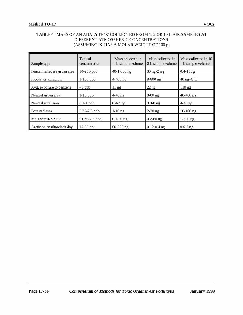
Method TO-17 VOCs
TABLE 4. MASS OF AN ANALYTE 'X' COLLECTED FROM 1, 2 OR 10 L AIR SAMPLES AT DIFFERENT ATMOSPHERIC CONCENTRATIONS (ASSUMING 'X' HAS A MOLAR WEIGHT OF 100 g)
Sample type Typical concentration
Mass collected in 1 L sample volume
Mass collected in 2 L sample volume
Mass collected in 10 L sample volume
Fenceline/severe urban area 10-250 ppb 40-1,000 ng 80 ng-2 Fg 0.4-10Fg
Indoor air sampling 1-100 ppb 4-400 ng 8-800 ng 40 ng-4Fg
Avg. exposure to benzene ~3 ppb 11 ng 22 ng 110 ng
Normal urban area 1-10 ppb 4-40 ng 8-80 ng 40-400 ng
Normal rural area 0.1-1 ppb 0.4-4 ng 0.8-8 ng 4-40 ng
Forested area 0.25-2.5 ppb 1-10 ng 2-20 ng 10-100 ng
Mt. Everest/K2 site 0.025-7.5 ppb 0.1-30 ng 0.2-60 ng 1-300 ng
Arctic on an ultraclean day 15-50 ppt 60-200 pg 0.12-0.4 ng 0.6-2 ng
Page 17-36 Compendium of Methods for Toxic Organic Air Pollutants January 1999

VOCs Method TO-17
COMPENDIUM METHOD TO-17 FIELD TEST DATA SHEET (FTDS)
I. GENERAL INFORMATION
PROJECT: SITE: LOCATION: INSTRUMENT MODEL NO.: PUMP SERIAL NO.:
DATE(S) SAMPLED: TIME PERIOD SAMPLED: OPERATOR: CALIBRATED BY: RAIN: YES NO
ADSORBENT CARTRIDGE INFORMATION:
Tube 1 Tube 2 Type:
Adsorbent: Serial No.:
Sample No.:
II. SAMPLING DATA
Tube Identifi-cation
Sampling Location
Ambient Temp., EF
Ambient Pressure,
in Hg
Flow Rate (Q), mL/min Sampling Period
Total Sampling
Time, min.
Total Sample Volume,
LTube 1 Tube 2 Start Stop
III. FIELD AUDIT
Tube 1 Tube 2
Audit Flow Check Within 10% of Set Point (Y/N)? pre- pre-
post- post-
CHECKED BY: DATE:
Figure 1. Compendium Method TO-17 Field Test Data Sheet.
January 1999 Compendium of Methods for Toxic Organic Air Pollutants Page 17-37

Method TO-17 VOCs
Figure 2. Example of construction of commercially available adsorbent tubes.
Page 17-38 Compendium of Methods for Toxic Organic Air Pollutants January 1999
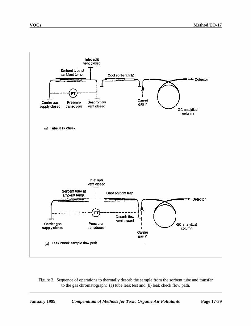
VOCs Method TO-17
Figure 3. Sequence of operations to thermally desorb the sample from the sorbent tube and transfer to the gas chromatograph: (a) tube leak test and (b) leak check flow path.
January 1999 Compendium of Methods for Toxic Organic Air Pollutants Page 17-39

Method TO-17 VOCs
Figure 3 (cont). Sequence of operations to thermally desorb the sample from the sorbent tube and transfer to the gas chromatograph: (c) purge to remove air and (d) gas phase internal standard
addition to sample tube.
Page 17-40 Compendium of Methods for Toxic Organic Air Pollutants January 1999

VOCs Method TO-17
Figure 3 (cont). Sequence of operations to thermally desorb the sample from the sorbent tube and transfer to the gas chromatograph: (e) primary (tube) desorption and (f) secondary (trap) desorption.
January 1999 Compendium of Methods for Toxic Organic Air Pollutants Page 17-41

Method TO-17 VOCs
Figure 4. Example of distributive air volume using adsorbent tube technology.
Page 17-42 Compendium of Methods for Toxic Organic Air Pollutants January 1999

VOCs Method TO-17
APPENDIX 1.
The following list includes safe sampling volume data generated by the UK Health and Safety Executive (4) on single sorbent bed 1/4 inch O.D. stainless steel tubes and compatible with a thermal desorption - capillary GC analytical procedure. It is provided as a resource to readers only. The recommendation for Tube Style 2 is based on the specific tube referenced in Section 6.1.2 and Table 3. Where tubes are not listed with safe sample volumes they have not been tested and their inclusion represents a suggestion only. Application to air sampling is subject to criteria listed in Section 14 of Compendium Method TO-17.
[Note: Combination tubes 1, 2, and 3 referenced in this Appendix are those adsorbent tubes described in Section 9.1.3.]
Suitable sorbents and SSV’s where availableCompound
Hydrocarbons
This procedure is suitable for all aliphatic, aromatic and cyclic hydrocarbons less volatile than ethane and more volatile than n-C20. These include:
n-Butane CS III, C 1000, Combination Tubes 2 or 3 or Spherocarb (SSV 820L).
n-Pentane CS III, C 1000, Spherocarb (SSV 30,000L), Combination Tubes 2 or 3 or Chromosorb 106 (SSV 5.5L).
n-Hexane Carbopack™ B, Combination Tubes 1, 2, 3 or Chromosorb 106 (SSV 30L).
Benzene Carbopack™ B, Combination Tubes 1, 2, 3 or Chromosorb 106 (SSV 26L) or Tenax (SSV 6L).
n-Heptane Carbopack™ B, Tenax (SSV 17L), Combination Tubes 1, 2, 3 or Chromosorb 106 (SSV 160L).
Toluene Carbopack™ B, Tenax (SSV 38L), Combination Tubes 1, 2, 3 or Chromosorb 106 (SSV 80L).
n-Octane Carbopack™ B, Tenax (SSV 700L) Combination Tubes 1, 2, 3 or Chromosorb 106 (SSV 1000L).
Ethylbenzene Carbopack™ B, Tenax (SSV 180L), Combination Tubes 1, 2, 3 or Chromosorb 106 (SSV 360L).
all Xylenes Carbopack™ B, Tenax (SSV 300L), Combination Tubes 1, 2, 3 or Chromosorb 106 (SSV 770L).
n-Nonane Carbopack™ C/B, Tenax (SSV 700L), Combination Tubes 1, 2 or 3 or Chromosorb 106 (SSV 7000L).
Styrene Carbopack™ C/B, Tenax (SSV 300L) or Combination Tubes 1, 2 or 3.
Isopropylbenzene Carbopack™ C/B, Tenax (SSV 480L) or Combination Tubes 1, 2 or 3.
n-Propylbenzene Carbopack™ C/B, Tenax (SSV 850L) or Combination Tubes 1, 2 or 3.
1-Methyl-3-ethylbenzene Carbopack™ C/B, Tenax (SSV 1000L) or Combination Tubes 1, 2 or 3.
1-Methyl-4-ethylbenzene Carbopack™ C/B, Tenax (SSV 1000L) or Combination Tubes 1, 2 or 3.
January 1999 Compendium of Methods for Toxic Organic Air Pollutants Page 17-43

Method TO-17 VOCs
Suitable sorbents and SSV’s where availableCompound
1,3,5-Trimethylbenzene Carbopack™ C/B, Tenax (SSV 1800L), Combination Tubes 1, 2 or 3 or Chromosorb 106 (SSV 2800).
Methylstyrene Carbopack™ C/B, Tenax (SSV 1200L) or Combination Tubes 1, 2 or 3.
Methyl-2-ethylbenzene Carbopack™ C/B, Tenax (SSV 1000L) or Combination Tubes 1, 2 or 3.
1,2,4-Trimethylbenzene Carbopack™ C/B, Tenax (SSV 1800L) or Combination Tubes 1, 2 or 3.
n-Decane Carbopack™ C/B, Tenax (SSV 2100L), Combination Tubes 1, 2 or 3 or Chromosorb 106 (SSV 37,000L).
1,2,3-Trimethylbenzene Carbopack™ C/B, Tenax (SSV 1800L) or Combination Tubes 1, 2 or 3.
n-Undecane Carbopack™ C/B, Tenax (SSV 12,000L) or Combination Tubes 1, 2 or 3.
n-Dodecane Carbopack™ C, Tenax (SSV 63,000L) or Combination Tubes 1 or 3.
Halogenated Hydrocarbons including PCBs
This procedure is suitable for all aliphatic, aromatic and cyclic halogenated hydrocarbons more volatile than n-C20. Examples include:
Dichloromethane CS III, C 1000, Spherocarb (SSV 200L) or Combination Tubes 2 or 3.
1,2-Dichloroethane CS III, C 1000, Spherocarb, Chrom. 106 (SSV 17L), Carbopack™ B, Tenax (SSV 5.4L) or Combination Tubes 1, 2 or 3.
1,1,1-Trichloroethane Spherocarb (SSV 8,000L), Chrom. 106 (SSV 8L), Carbopack™ B, or Combination Tubes 1, 2 or 3.
Carbontetrachloride Chrom. 106 (SSV 22L), Carbopack™ B, Tenax (SSV 6.2L) or Combination Tubes 1, 2 or 3.
Trichloroethylene Chrom. 106, Carbopack™ B, Tenax (SSV 5.6L) or Combination Tubes 1, 2 or 3.
1,1,2-Trichloroethane Chrom. 106, Carbopack™ B, Tenax (SSV 34L) or Combination Tubes 1, 2 or 3.
Tetrachloroethylene Chrom. 106, Carbopack™ B, Tenax (SSV 48L) or Combination Tubes 1, 2 or 3.
Chlorobenzene Chrom. 106, Carbopack™ B, Tenax (SSV 26L) or Combination Tubes 1, 2 or 3.
1,1,1,2-Tetrachloroethane Chrom. 106, Carbopack™ B, Tenax (SSV 78L) or Combination Tubes 1, 2 or 3.
1,1,2,2-Tetrachloroethane Chrom. 106, Carbopack™ B, Tenax (SSV 170L) or Combination Tubes 1, 2 or 3.
Page 17-44 Compendium of Methods for Toxic Organic Air Pollutants January 1999

VOCs Method TO-17
Suitable sorbents and SSV’s where availableCompound
Alcohols
This procedure is suitable for alcohols more volatile than n-C20 and sufficiently stable to be analyzed by conventional GC techniques. Examples include:
Methanol CSIII, C1000, Spherocarb (SSV 130L) or Combination Tubes 2 or 3.
Ethanol CSIII, C1000, Spherocarb (SSV 3500L) or Combination Tubes 2 or 3.
n-Propanol Porapak N (SSV 20L), Chrom 106 (SSV 8L), Carbopack™ B or Combination Tubes 1, 2 or 3.
Isopropanol Chrom 106 (SSV 44L), Carbopack™ B or Combination Tubes 1, 2 or 3.
n-Butanol Chrom 106 (SSV 50L), Carbopack™ B, Porapak N (SSV 5L), Tenax (SSV 5L) or Combination Tubes 1, 2 or 3.
iso-Butanol Chrom 106 (SSV 30L), Carbopack™ B, Tenax (SSV 2.8L) or Combination Tubes 1, 2 or 3.
Octanol Tenax (SSV 1400L), Carbopack™ C or Combination Tubes 1 or 3.
Esters and Gycol Ethers
This procedure is suitable for all esters and glycol ethers more volatile than n-C20 and sufficiently stable to be analyzed by conventional GC techniques. Examples include:
Methylacetate Chromosorb 106 (SSV 2.6L), Carbopack™ B or Combination Tubes 1, 2 or 3.
Ethylacetate Chromosorb 106 (SSV 20L), Carbopack™ B, Tenax (SSV 3.6L) or Combination Tubes 1, 2 or 3.
Propylacetate Chromosorb 106 (SSV 150L), Carbopack™ B, Tenax (SSV 18L) or Combination Tubes 1, 2 or 3.
Isopropylacetate Chromosorb 106 (SSV 75L), Carbopack™ B, Tenax (SSV 6L) or Combination Tubes 1, 2 or 3.
Butylacetate Chromosorb 106 (SSV 730L), Carbopack™ B, Tenax (SSV 85L) or Combination Tubes 1, 2 or 3.
Isobutylacetate Chromosorb 106 (SSV 440L), Carbopack™ B, Tenax (SSV 130L) or Combination Tubes 1, 2 or 3.
Methyl-t-butyl ether Chromosorb 106 (SSV >6L), Carbopack™ B or Combination Tubes 1, 2 or 3.
t-Butylacetate Chromosorb 106 (SSV 160L), Carbopack™ B or Combination Tubes 1, 2 or 3.
Methylacrylate Chromosorb 106, Carbopack™ B, Tenax (SSV 6.5L) or Combination Tubes 1, 2 or 3.
January 1999 Compendium of Methods for Toxic Organic Air Pollutants Page 17-45

Method TO-17 VOCs
Suitable sorbents and SSV’s where availableCompound
Ethylacrylate Chromosorb 106, Carbopack™ B, Tenax (SSV 60L) or Combination Tubes 1, 2 or 3.
Methylmethacrylate Chromosorb 106, Carbopack™ B, Tenax (SSV 27L) or Combination Tubes 1, 2 or 3.
Methoxyethanol Chromosorb 106 (SSV 5L), Carbopack™ B, Tenax (SSV 3L) or Combination Tubes 1, 2 or 3.
Ethoxyethanol Chromosorb 106 (SSV 75L), Carbopack™ B, Tenax (SSV 5L) or Combination Tubes 1, 2 or 3.
Butoxyethanol Chromosorb 106, Carbopack™ B, Tenax (SSV 35L) or Combination Tubes 1, 2 or 3.
Methoxypropanol Chromosorb 106, Carbopack™ B, Tenax (SSV 13L) or Combination Tubes 1, 2 or 3.
Methoxyethylacetate Chromosorb 106 (SSV 860L), Carbopack™ B, Tenax (SSV 8L) or Combination Tubes 1, 2 or 3.
Ethoxyethylacetate Chromosorb 106 (SSV 4000L), Carbopack™ B, Tenax (SSV 15L) or Combination Tubes 1, 2 or 3.
Butoxyethylacetate Chromosorb 106, Carbopack™ B, Tenax (SSV 150L) or Combination Tubes 1, 2 or 3.
Aldehydes and Ketones
This procedure is suitable for all aldehydes and ketones more volatile than n-C20 and sufficiently stable to be analyzed using conventional GC techniques. Examples include:
Acetone CSIII, C1000, Spherocarb, Chrom 106 (SSV 1.5L) or Combination Tubes 2 or 3.
Methylethylketone Chromosorb 106 (SSV 10L), Tenax (SSV 3.2L), Porapak N (SSV 50L) (2-butanone) Carbopack™ B or Combination Tubes 1, 2 or 3.
n-Butanal Chromosorb 106, Carbopack™ B, Porapak N (SSV 50L) or Combination Tubes 1, 2 or 3.
Methylisobutylketone Chromosorb 106 (SSV 250L), Tenax (SSV 26L), Carbopack™ B or Combination Tubes 1, 2 or 3.
Cyclohexanone Chromosorb 106, Tenax (SSV 170L), Carbopack™ B or Combination Tubes 1, 2 or 3.
3,5,5-Trimethylcyclohex-2- Tenax (SSV 5600L), Carbopack™ B or Combination Tubes 1 or 3. enone
Furfural Tenax (SSV 300L), Carbopack™ B or Combination Tubes 1, 2 or 3.
Page 17-46 Compendium of Methods for Toxic Organic Air Pollutants January 1999

VOCs Method TO-17
Suitable sorbents and SSV’s where availableCompound
Miscellaneous VOCs
This procedure is suitable for the analysis of most VOCs in air. It is generally compatible with all organics less volatile than ethane, more volatile than n-C20 and sufficiently stable to be analyzed using conventional GC techniques. Examples include:
Acetonitrile Porapak N (SSV 3.5L), CSIII, C1000 or Combination Tubes 2 or 3.
Acrylonitrile Porapak N (SSV 8L), Carbopack™ B or Combination Tubes 1, 2 or 3.
Propionitrile Porapak N (SSV 11L), Carbopack™ B or Combination Tubes 1, 2 or 3. aMaleic anhydride Tenax (SSV 88L), Chrom. 106, Carbopack™ B or Combination Tubes 1, 2
or 3.
Pyridine Tenax (SSV 8L), Porapak N (SSV 200L) Chrom. 106, Carbopack™ B or Combination Tubes 1, 2 or 3.
Aniline Tenax (SSV 220L), Chrom. 106, Carbopack™ B or Combination Tubes 1, 2 or 3.
Nitrobenzene Tenax (SSV 14,000L) Carbopack™ C or Combination Tubes 1 or 3.
Acetic acid Porapak N (SSV 50L), Carbotrap™ B or Combination Tubes 1, 2 or 3.
Phenol Tenax (SSV 240L) or combination tube 1.
January 1999 Compendium of Methods for Toxic Organic Air Pollutants Page 17-47

Method TO-17 VOCs
APPENDIX 2.
LINEARITY TESTING OF ONE SORBENT TUBE/FOCUSING TUBE COMBINATION
Introduction
Automated gas chromatographs such as those used at network monitoring stations for hourly updates of volatile organic compounds (VOCs) have a solid adsorbent concentrator for the VOCs. This unit is comparable to the sorbent tubes being discussed in this document. The table below shows the results of sampling a synthetic mixture of the Compendium Method TO-14 target list in humidified zero air (approximately 70% RH at 25EC). Sampling occurred for 6, 12, and 24 min at a rate of 80 mL/min giving a total sampling volume of 480, 960, and 1920 mL. These results are similar to the determination of safe sampling volume and the amount of material collected should be related linearly to the sample period. The results indicate that breakthrough has not occurred to any appreciable extent at a sampling volume of approximately 2 L for the stated experimental conditions. The response measured is the response of chlorine from an atomic emission detector after chromatographic separation. The sorbent tube mix was Carbotrap™ C/Carbotrap™ B/Carboxen™ 1000 and the focusing tube mix was Tenax-TA/Silica Gel/Ambersorb XE-340/Charcoal. The primary tube was 6 mm O.D. with 4 mm I.D., 110 mm in length. The focusing tube was 6 mm O.D., 0.9 mm I.D., 185 mm in length. The packing lengths for the sorbent tube per sorbent type were: 1.27 cm, 2.86 cm, and 3.18 cm, respectively. The packing lengths for the focusing tube per sorbent type were: 5.08 cm, 2.54 cm, and 1.27 cm.
Linearity test
[Note: Actual sampling volumes were 490, 980, and 1960 instead of 1/2,1, and 2L as listed for convenience in the table below. The response is obtained as chlorine response on an atomic emission detector. Compounds corresponding to the numbered compounds in the table are identified on the following page.]
Cpd. 1/2 L 1 L 2 L 2L/1L 2L/(1/2L) 1L/(1/2L)
% Diff (2L/0.5L) vs.
4
1 1255.4 2402.9 5337.2 2.22 4.25 1.91 -6.28
2 711.82 1802.2 3087 1.71 4.34 2.53 -8.42
3 2079.4 4853 9386 1.93 4.51 2.33 -12.85
4 978.14 2381.3 4680.1 1.97 4.78 2.43 -19.62
6 1155.7 2357.1 4725.2 2.00 4.09 2.04 -2.22
7 3072.8 6764.4 13662 2.02 4.45 2.20 -11.15
8 2337.3 4356.1 8697.2 2.00 3.72 1.86 6.97
9 3041.7 5986.6 11525 1.93 3.79 1.97 5.28
10 1061.7 2183.6 4296.5 1.97 4.05 2.06 -1.17
11 3800.5 7726.7 15182 1.96 3.99 2.03 0.13
12 2386.9 4877.5 9669 1.98 4.05 2.04 -1.27
13 2455.4 5063.5 9986.6 1.97 4.07 2.06 -1.68
14 3972.6 8118.4 15985 1.97 4.02 2.04 -0.60
15 2430.9 4947.9 9756.1 1.97 4.01 2.04 -0.33
16 6155.4 9247.4 16942 1.83 2.75 1.50 31.19
Page 17-48 Compendium of Methods for Toxic Organic Air Pollutants January 1999
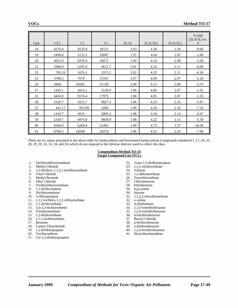
VOCs Method TO-17
Cpd. 1/2 L 1 L 2 L 2L/1L 2L/(1/2L) 1L/(1/2L)
% Diff (2L/0.5L) vs.
4
18 4270.4 9233.8 18721 2.03 4.38 2.16 -9.60
19 2494.8 5115.2 10087 1.97 4.04 2.05 -1.08
20 4023.9 8379.4 16672 1.99 4.14 2.08 -3.58
21 1086.8 2295.4 4611.7 2.01 4.24 2.11 -6.08
22 793.33 1670.1 3375.2 2.02 4.25 2.11 -6.36
23 3708.2 7679 15165 1.97 4.09 2.07 -2.24
26 5094 10582 21139 2.00 4.15 2.08 -3.74
27 1265.1 2615.1 5136.9 1.96 4.06 2.07 -1.51
31 4434.9 9176.4 17975 1.96 4.05 2.07 -1.33
36 2320.7 5015.7 9827.3 1.96 4.23 2.16 -5.87
37 441.17 953.09 1894 1.99 4.29 2.16 -7.33
38 1410.7 3015 5895.2 1.96 4.18 2.14 -4.47
39 2338.7 4974.8 9858.8 1.98 4.22 2.13 -5.39
40 2640.9 6269.4 12495 1.99 4.73 2.37 -18.28
41 6796.5 14938 29274 1.96 4.31 2.20 -7.68
There are no values presented in the above table for hydrocarbons and brominated hydrocarbons (compounds numbered 5, 17, 24, 25, 28, 29, 30, 32, 33, 34, and 35) which do not respond to the chlorine detector used to collect this data.
Compendium Method TO-14 Target Compound List (TCL)
1. Dichlorodifluoromethane 22. Trans-1,3-dichloropropene 2. Methyl Chloride 23. 1,1,2-trichloroethane 3. 1,2-dichloro-1,1,2,2-tetrafluoroethane 24. Toluene 4. Vinyl Chloride 25. 1,2-dibromoethane 5. Methyl Bromide 26. Tetrachloroethene 6. Ethyl Chloride 27. Chlorobenzene 7. Trichlorofluoromethane 28. Ethylbenzene 8. 1,1-dichloroethene 29. m,p-xylene 9. Dichloromethane 30. Styrene 10. 3-chloropropene 31. 1,1,2,2-tetrachloroethane 11. 1,1,2-trichloro-1,2,2-trifluoroethane 32. o-xylene 12. 1,1-dichloroethane 33. 4-ethyltoluene 13. Cis-1,2-dichloroethene 34. 1,3,5-trimethylbenzene 14. Trichloromethane 35. 1,2,4-trimethylbenzene 15. 1,2-dichloroethane 36. m-dichlorobenzene 16. 1,1,1-trichloroethane 37. Benzyl Chloride 17. Benzene 38. p-dichlorobenzene 18. Carbon Tetrachloride 39. o-dichlorobenzene 19. 1,2-dichloropropane 40. 1,2,4-trichlorobenzene 20. Trichloroethene 41. Hexachlorobutadiene 21. Cis-1,3-dichloropropene
January 1999 Compendium of Methods for Toxic Organic Air Pollutants Page 17-49