method statement draft v2 - crossrail learning legacy · stating that a method statement for the...
TRANSCRIPT


Liverpool Street: Method Statement for Verizon works at Old Broad Street in relation to the Scheduled Monument – City Wall (LO26N)
Document uncontrolled once printed. All controlled documents are saved on the CRL Document System
© Crossrail Limited UNCONTROLLED
1 Introduction
1.1 Background
1.1.1 This method statement sets out the procedure for preservation in situ of Scheduled Monument LO26N – the City Wall, in relation to the Verizon utility diversion works to be carried out at the southern end of Old Broad Street.
1.1.2 The Crossrail Act 2008 contains clauses that disapply the usual statutory controls for works that affect Scheduled Monuments. Consequently, the Nominated Undertaker (Crossrail) has signed the Deed relating to works affecting scheduled monuments in the City of London (Crossrail Act 2008), hereafter referred to in this document as ‘the Deed’, with the Secretaries of State and English Heritage. The Deed requires details of works that may affect Scheduled Monuments to be approved by the Secretaries of State. The Deed in full is reproduced in Appendix B.
1.2 Purpose
1.2.1 Clause 3.2 of the Deed states that: ‘Before commencing relevant construction works for an affected monument, the nominated undertaker must submit to the Secretaries of State the works details for those works for their approval in writing’.
1.2.2 Furthermore, Clause 3.4 of the Deed states that ‘the nominated undertaker must at the same time as submitting the works details under clause 3.2 send that information to English Heritage’. Clause 3.4 part (b) also states that ‘the Secretaries of State must not approve the works details submitted to them unless English Heritage have either given their comments on those details to the Secretaries of State or have indicated that they do not need to comment’.
1.2.3 Schedule 1 Part 2 of the Deed sets out the required Method Statement details, stating that a method statement for the utility diversion works having an impact on an affected monument is to show how damage to the monument is, so far as reasonably practicable, to be avoided or minimised, including:
(a) where works for utilities are required in Moorgate, Circus Place, Blomfield Street, Bishopsgate and London Wall which have an impact on an affected monument, the location and the depth of the routes to accommodate utility trenches and their relationship with the monument and modern materials above;
(b) suitable protective measures (both temporary and permanent) where works for utilities have an impact on an affected monument.
1.2.4 The aim of this method statement and accompanying appendices is to obtain the decision of the Secretaries of State, which Clause 3.5 of the Deed states may be –
(a) approval should be withheld for specified reasons,
(b) approval should be given (in which case it may be given subject to specified amendments or requirements).

Liverpool Street: Method Statement for Verizon works at Old Broad Street in relation to the Scheduled Monument – City Wall (LO26N)
Document uncontrolled once printed. All controlled documents are saved on the CRL Document System
© Crossrail Limited UNCONTROLLED
1.2.5 This document describes how the risk of encountering the scheduled monument is managed and sets out the strategy for ensuring that it is not damaged by the works. This document only applies to Crossrail works.
1.3 Structure of this Method Statement
1.3.1 This method statement is organised in two parts. The first half will describe the monument and the archaeological works carried out thus far to satisfy the process set out in the Deed. The second half will present the construction methodology and mitigation strategy to avoid/protect the monument should it be encountered.
2 Scheduled Monument LO26N – City Wall
2.1 Description and significance of Scheduled Monument LO26N
2.1.1 Schedule 1, Part 3 of the Deed sets out background information describing the Scheduled Monument LO26N:
….The parts of the monuments which might potentially be affected by the utility diversions are buried below ground level. It is considered that earlier utilities have previously been dug at least part-way through localised parts of the monuments. The current English Heritage mapping of the buried monuments is not considered to be accurate in detail.
The wall around the landward side of the Roman city of Londinium was built in c AD 200. Bishopsgate was one of the five original major gates, later reconstructed to project c 8m from the wall line. The wall was refurbished in the medieval period, the gates rebuilt, and new ones, including Moor Gate, were added. Further refurbishment took place in the 17th century, and large portions of the wall were demolished from the mid 18th century onwards.
Scheduled monument LO26N, London Wall: remains of Roman and medieval wall from the west end of All Hallows Church to 38 Camomile Street
Section LO26N is c 235m long, and extends eastwards from All Hallows Church to 38 Camomile Street. Unlike section LO26P, the majority of this section runs beneath buildings to the north of London Wall and Wormwood Street. It might, therefore, only be affected by utility diversions where it crosses the southern ends of Old Broad Street and Bishopsgate. This section includes the site of the former Bishopsgate, which projects north of the line of the wall.
The centre of this section lies at approximately NGR 532820 181525. The extent of survival of the buried parts of the wall and the Bishopsgate is uncertain. The top of the surviving wall at Bishopsgate was previously observed at c 1.6m below ground level. The western end at All Hallows Church survives above ground level.
The Bishopsgate is believed to have originally been a Roman gateway, with a gatehouse projecting to the rear of the wall by c 6.1m. The medieval gateway which replaced it was rebuilt in 1479, and repaired in 1648. The gateway was replaced in the 17th century, and rebuilt again in 1735, but demolished in 1761. The location of the gate is poorly defined from archaeological records, but as currently mapped by English Heritage, it extends c 4m to 5m north of the wall, although this omits the early gatehouse projecting to the rear.

Liverpool Street: Method Statement for Verizon works at Old Broad Street in relation to the Scheduled Monument – City Wall (LO26N)
Document uncontrolled once printed. All controlled documents are saved on the CRL Document System
© Crossrail Limited UNCONTROLLED
2.2 Schedule 2 Assessment Process
2.2.1 Schedule 2 of the Deed sets out a process to be employed by Crossrail design engineers to inform the design of the utilities diversions. The assessment stages set out in Schedule 2, and the works carried out by Crossrail to satisfy that process, are set out in this section.
Stage 1 – Detailed desk-based assessment
2.2.2 A desk based assessment was carried out by Crossrail and Museum of London Archaeology in 2008/09 to collate and map past observations of the City Wall and thereby understand the potential for encountering the scheduled monument during utilities works and consequently inform the necessity for a trial trench evaluation.
2.2.3 Refer to Appendix C for the full report. The results relating to the southern area of Old Broad Street are summarised below:
• A survey in 1991-92 observed the outer face of the City Wall to the east of Old Broad Street in the basement of 54-62 New Broad Street.
• The external face of the City Wall was identified in test pits to the east and west of the All Hallows on the Wall church (CAP86) to the east of Old Broad Street (figure 1)
• The City Wall forms the northern boundary of the All Hallows on the Wall churchyard, exposed and recorded to a height of 12ft (roughly contemporary ground level) in 1905 (figure 1).
• The City Wall was observed to its full width in the basement of 23-24 Wormwood Street, to the east of Old Broad Street during investigations in 1994 (WOE94 – figure 1).
• The alignment of the City Wall that constitutes section LO26N of the Scheduled Monument is extrapolated from observations at All Hallows on the Wall and at 23-24 Wormwood Street, to the west and east of Old Broad Street respectively. This alignment runs beneath Old Broad Street, however, the preservation of the City Wall in Old Broad Street is unknown.
Figure 1 Alignment of the LO26N City Wall (Crossrail 2009a)
LO26N
Old Broad Street

Liverpool Street: Method Statement for Verizon works at Old Broad Street in relation to the Scheduled Monument – City Wall (LO26N)
Document uncontrolled once printed. All controlled documents are saved on the CRL Document System
© Crossrail Limited UNCONTROLLED
Stage 2 – Non-intrusive fieldwork
2.2.4 Museum of London Archaeology (MoLA) advised Crossrail that Ground Penetrating Radar (GPR) is not an effective methodology in most urban areas due to the high level of interference from modern material which might overlie archaeological deposits.
2.2.5 MoLA reviewed the results of geotechnical investigations and identified an anomaly in an area to the east of Moorgate, where part of the City Wall was expected. Consequently, the Ground Penetrating Radar results were reviewed by Stratascan, a professional geophysical and specialist survey service often used to survey archaeological projects. Stratascan concluded that no archaeological features could be definitely identified, and that further radar work was not likely to produce reliable results. The decision was therefore taken to move directly from Stage 1 detailed desk-based assessment to Stage 3 intrusive fieldwork. Refer to Appendix D for the e-mail correspondence relating to the decision not to proceed with radar survey.
Stage 3 – Intrusive fieldwork
2.2.6 In accordance with Schedule 2 of the Deed intrusive fieldwork comprises exploratory field evaluation (trial pits or trenches), targeting key areas where the Crossrail utility works intersect the predicted line of the Scheduled Monument and further data is required to understand the risk of encountering it.
2.2.7 An archaeological watching brief and evaluation was carried out by Crossrail and MoLA on ten 1.5m deep trial trenches in 2009. Of the ten trenches, trench LIV19 was located at the southern end of Old Broad Street on the conjectured alignment of the London Wall LO26N. Refer to figures 2 and 3 for the location of LIV19.
2.2.8 Refer to Appendix E for the full evaluation report prepared by MoLA. The results relating to LIV19 are summarised below:
• Trench excavated to 1.5m below ground level.
• Existing utilities occupied the full 1.5m deep trench; also the remains of an 18th or 19th century cellar were identified.
• The Scheduled Monument was not encountered.

Liverpool Street: Method Statement for Verizon works at Old Broad Street in relation to the Scheduled Monument – City Wall (LO26N)
Document uncontrolled once printed. All controlled documents are saved on the CRL Document System
© Crossrail Limited UNCONTROLLED
Figure 2 LIV19 trial trench at the southern end of Old Broad Street (Crossrail 2009b)
Figure 3 Plan of LIV19 and cellar walls (Crossrail 2009b)

Liverpool Street: Method Statement for Verizon works at Old Broad Street in relation to the Scheduled Monument – City Wall (LO26N)
Document uncontrolled once printed. All controlled documents are saved on the CRL Document System
© Crossrail Limited UNCONTROLLED
2.2.9 Figure 4 and 5 (not to scale) show the concentration and depths of existing utilities and obstructions exposed in trench LIV19 in the section of Old Broad Street through which the Verizon ducts will be installed. Figure 5 shows modern disturbance to a minimum of 850mm below ground level, which is deeper than the proposed Verizon works. Figure 4 shows photographs of the exposed utilities in trench LIV19.
Figure 4 Photographs of the exposed utilities in trench LIV19 (JB Riney 2009)

Liverpool Street: Method Statement for Verizon works at Old Broad Street in relation to the Scheduled Monument – City Wall (LO26N)
Document uncontrolled once printed. All controlled documents are saved on the CRL Document System
© Crossrail Limited UNCONTROLLED
Figure 5 Diagram showing the concentration and depth of existing utilities in LIV19, not to scale
(JB Riney 2009)
Consultation with English Heritage
2.2.10 In accordance with clause 2.2 of the Deed, before making a request for approval of the works under clause 3.2, Crossrail consulted English Heritage (Jane Siddell) on 14th October 2011. The full minutes of the meeting are provided in Appendix G, the key points are summarised below.
2.2.11 English Heritage stated that the location (figure 2) of the evaluation trench LIV19 does not comprehensively prove the absence of the Scheduled Monument at the location of the Verizon works, however no further archaeological evaluation is required if:
1. a strategy is provided setting out how the monument will be avoided/protected if it is encountered; and
2. that there will be an archaeological watching brief during the works at the monument location and within a buffer zone to the north and south.
Liverpool Street: Method Statement for Verizon works at Old Broad Street in relation to the Scheduled Monument – City Wall (LO26N)
Document uncontrolled once printed. All controlled documents are saved on the CRL Document System
© Crossrail Limited UNCONTROLLED
2.2.12 Works details are to be submitted as per Schedule 3 of the Deed.
2.2.13 Consultation with English Heritage also took place in 2009 for the trial trench LIV19 and other trenches in the area. English Heritage (Jane Siddell) provided a specification for protection measures to be installed around the Scheduled Monument prior to backfilling. The same specification is set out in section 4 of this Method Statement, to be enacted should Scheduled Monument LO26N be exposed during the Verizon works.
2.3 Summary of the survival of Scheduled Monument LO26N at Old Broad Street
2.3.1 The results of the assessment process carried out in accordance with Schedule 2 of the Deed are summarised below:
1. The projected alignment of Scheduled Monument LO26N intersects Old Broad Street and the Verizon works pass through that alignment.
2. The evaluation trench LIV19 did not identify Scheduled Monument LO26N and demonstrated modern disturbance to a depth up to 1.5m below ground level.
3. The evaluation trench LIV19 did not expose the entirety of the projected route of the London Wall and so therefore the risk of encountering it during Verizon works cannot be completely discounted. However this is considered unlikely given that the maximum excavation for the Verizon works is approximately 600mm below ground level only.

Liverpool Street: Method Statement for Verizon works at Old Broad Street in relation to the Scheduled Monument – City Wall (LO26N)
Page 11 of 22 Document uncontrolled once printed. All controlled documents are saved on the CRL Document System
© Crossrail Limited UNCONTROLLED
3 Scope of Works
3.1.1 The full scope of work is set out in the C503 Contractor’s Method Statement in Appendix F.
3.1.2 The works are required to divert public utilities away from the footprint of the future Liverpool Street Crossrail ticket hall at Liverpool Street.
3.1.3 The works are programmed for late 2011/early 2012.
3.1.4 The works will take place in Eldon Street, Liverpool Street, Sun Street, New Broad Street, Old Broad Street and Blomfield Street. This document deals only with works at the southern end of Old Broad Street.
3.1.5 The general works comprise excavations for joint bays, duct routes, cable pits and access chambers, however, the works that pass through the projected alignment of Scheduled Monument LO26N will comprise only a duct route.
3.1.6 The following construction methodology is reproduced from the C503 Contractor’s method statement:
1. Permit to penetrate (VCUK) and permit to dig (sub-contractor) need to be in place and checked by the VCUK Supervisor.
2. Prior to the ground being broken the excavation area will be scanned by a trained subcontractor operative with a CAT and signal generator and checked against the Permit to Penetrate. Existing service records will be cross-checked.
3. Services detected will be marked on the surface using line spray within and 2m beyond the footprint of the area to be excavated wherever possible.
4. Based on the utilities agree with the VCUK Supervisor a suitable location for starting excavation. If location for excavation is moved, then start again from step 1.
5. The tarmac will be saw-cut using floor saw and broken out using a 6t excavator with hydraulic breaker attachment. Where this is not possible, a hand-held breaker will be used.
6. The 300mm mass concrete sub-base will be broken out by using the excavator. A banksman will be in attendance at all times whilst plant is in operation. Where this is not possible, a hand-held breaker will be used by the operatives.
7. Made ground will be excavated by hand around the services to form trench. No excavation will be undertaken using mechanical excavator within 500mm of known or suspected services.
8. Waste material will be transferred to the Liverpool Street compound using a dumper where it will be stored before it is tested and removed by the appointed subcontractor.
9. Where an inspection deems the ground unstable, temporary ground support will be installed to a design approved by VCUK. A VCUK Engineer will carry out inspections of all excavations on a daily basis.

Liverpool Street: Method Statement for Verizon works at Old Broad Street in relation to the Scheduled Monument – City Wall (LO26N)
Document uncontrolled once printed. All controlled documents are saved on the CRL Document System
© Crossrail Limited UNCONTROLLED
10. If services further to the ones known are identified, works will stop and refer back to VCUK supervision and management for guidance.

Liverpool Street: Method Statement for Verizon works at Old Broad Street in relation to the Scheduled Monument – City Wall (LO26N)
Document uncontrolled once printed. All controlled documents are saved on the CRL Document System
© Crossrail Limited UNCONTROLLED
4 Approach to Mitigation at Scheduled Monument LO26N
4.1.1 Alongside the Contractor’s construction methodology set out in section 3 the following mitigation, agreed in consultation with English Heritage, will be in place during the works at the southern part of Old Broad Street.
4.1.2 Continuous archaeological watching brief will be in place during works over the alignment of the Scheduled Monument and within a buffer zone of 6m to the north and south of the alignment. The area of continuous watching brief is shown on drawing CRL1-XRL-U-DDA-C101-00178, Appendix 1.
4.1.3 The general watching brief already in place for Crossrail utilities diversions at Liverpool Street will cover works outside of the 6m buffer zones. Refer to the Site Specific Written Scheme of Investigation (C138-MMD-T1-RST-C101-00001).
4.1.4 English Heritage will be informed by the Employer’s Archaeologist one week prior to the start of works at the locations shown on drawing CRL1-XRL-U-DDA-C101-00178, Appendix 1, to allow a site visit to be organised.
4.1.5 Should the Scheduled Monument be encountered, the Principal Contractor will stop works immediately. Under no circumstances shall the works impact the Scheduled Monument. If any section of the Scheduled Monument is exposed it shall be:
• Avoided by the duct route – e.g. the duct route will be shallower to avoid the monument, or if this is not possible the route will be moved east or west until a suitable space for the duct route is identified.
• Recorded and surveyed in full by the attending Archaeological Contractor;
• Protected by a geotextile membrane and layer of sand (see 4.1.6) during reinstatement to the satisfaction of the Archaeological Contractor, Employer’s Archaeologist and English Heritage.
4.1.6 The specification for protective materials for preservation in situ of the City Wall (Scheduled Monument) were supplied by the English Heritage Inspector of Ancient Monuments (Jane Sidell) to MoLA in advance of the evaluation fieldwork in 2009. The same specification shall be applied as follows:
• Geotextile: water-porous geotextile
• Sand: effectively iron free, pale coloured (in the 7.5 YR, 10YR and 2.5 YR Munsell chart colour bracket), non-calcareous, relatively clay free, with particle size of no less than 98% below 63 microns and no more than 2% above 2mm, Loss on ignition value to be no more than 2%, e.g. ‘Kingsley No 1’.
Liverpool Street: Method Statement for Verizon works at Old Broad Street in relation to the Scheduled Monument – City Wall (LO26N)
Page 14 of 22 Document uncontrolled once printed. All controlled documents are saved on the CRL Document System
© Crossrail Limited UNCONTROLLED
5 Reference documents
Crossrail 2009a. Utilities Diversions: London Wall, Moorgate, Blomfield Street, Old Broad Street, Bishopsgate, Past Observations of City Wall. October 2008. Museum of London Archaeology Service.
Crossrail 2009b. Liverpool Street & Moorgate Utilities Trial Trenches Archaeological Watching Brief & Evaluation. Document Number CR-PN-LIV-EN-MS-00003.
Crossrail 2009c. Crossrail Act 2008: Deed relating to works affecting scheduled monuments in the City of London.
Crossrail 2009d. Liverpool Street & Moorgate Utilities Trial Trenches. Archaeological Watching Brief & Evaluation Method Statement.
Crossrail 2010. Archaeological Watching Brief & Evaluation, Utilities trial trenches, Liverpool Street and London Wall v2.0. Museum of London Archaeology Service.
Crossrail 2011. C503 – Liverpool Street Method Statement Utilities Diversions – Excavation, Duct Installation, Backfilling. CRL Document Number: C503-VIN-C-GMS-C101-50010.
JB Riney 2009. Liverpool Street Area – Trial Hole Number: 19 – Old Broad Street, Utility Trial Trench Report.

Liverpool Street: Method Statement for Verizon works at Old Broad Street in relation to the Scheduled Monument – City Wall (LO26N)
Document uncontrolled once printed. All controlled documents are saved on the CRL Document System
© Crossrail Limited UNCONTROLLED
Appendix A Drawing

34
X=83416.6736,Y=36169.5141,Z=0.0000
X=83428.9850,Y=36166.6764,Z=0.0000
X=83427.5514,Y=36160.8502,Z=0.0000
X=83415.1487,Y=36163.6820,Z=0.0000
X=83414.4123,Y=36160.2072,Z=0.0000
X=83427.1223,Y=36156.9462,Z=0.0000
X=83425.6675,Y=36151.1252,Z=0.0000
X=83412.9354,Y=36154.3918,Z=0.0000
X=83428.0650,Y=36160.7329,Z=0.0000
X=83429.5090,Y=36166.5475,Z=0.0000
1.2
0d
0.60d
2/1
0.60d
0.5
0d
0.6
0d
0.5
0d
0.50d
0.50d0.50d
0.50d2/10.50d2/1
www.crossrail.co.uk
Auth :
E14 5LQ
London
Canary Wharf
25 Canada Square
Crossrail LimitedOriginator :
Location :
Scale :
Title :
DateRev. Description
Co
py
Ap
pr
ove
d f
or
Desi
gn -
Create
d:
01-
NO
V-
20
11
Contract :
' CrossrailChk :
App :
By :
@ A3
Notes:
Suit :Drg No : Rev :By Chkd App Auth
using an approved safe method of working.
and competent contractors carrying out the work
These notes are based on the use of experienced
Diii.
Dii.
Di.
Dismantling/Demolition (Future)
Miii.
Mii.
Mi.
Maintenance
Oiii.
Oii.
Oi.
Operations
Ciii.
Cii.
Ci.
Construction
normally associated with this type of work:
Notes below are additional to hazards/risks
Safety, Health and Environmental Information
RE
ST
RIC
TE
D
1:200
Liverpool Street - Eastern Ticket Hall
Crossrail Ltd
Liverpool Street Stn
CRL1-XRL-U-DDA-C101-00178
-
S4
Crossrail Line 1 Programme
-
-
---
Verizon - Existing Route (Surveyed)
Verizon - Proposed Diversion Route
6.0
0
6.0
0
18th/19th Century cellar walls
OL
D B
RO
AD S
T.
NEW BROAD ST.
LONDON WALL
KEY
Location PlanNTS
All dimensions are in metres unless specified otherwise.
CR-STD-010.
Ordnance Datum Newlyn. See Crossrail standard
the London height datum which is 100 metres below
Coordinates to the London Survey Grid, heights to
from the Crossrail survey team.
Confirmation of all survey data must be obtained
3.
2.
1.
N
04m 4m 8m 12m 16m 20m
Scheduled Monument of London Wall
X=83415.1487,Y=36163.6820,Z=0.0000
LIV19 Evaluation Trench
X=83416.6736,Y=36169.5141
X=83415.1487,Y=36163.6820
X=83414.4123,Y=36160.2072
X=83412.9354,Y=36154.3918
X=83425.6675,Y=36151.1252
X=83427.1223,Y=36156.9462
Existing Verizon Utilities at
X=83428.0650,Y=36160.7329,Z=0.0000
X=83428.0650,Y=36160.7329
X=83429.5090,Y=36166.5475
LIV19 Evaluation Trench
HCMHFirst Issue01/11/2011P01
(Archeological watching brief area)Scheduled Monument of London Wall
(Archeological watching brief area)6m Buffer zone from London Wall
Key amended
M.HOPPER
01/11/2011 MHP02
P02
H.CASEY
HC S.SHEPHERDSS
Fit for auth
orisation

Liverpool Street: Method Statement for Verizon works at Old Broad Street in relation to the Scheduled Monument – City Wall (LO26N)
Document uncontrolled once printed. All controlled documents are saved on the CRL Document System
© Crossrail Limited UNCONTROLLED
Appendix B Crossrail Act 2008: Deed relating to works affecting scheduled monuments in the City of London


Liverpool Street: Method Statement for Verizon works at Old Broad Street in relation to the Scheduled Monument – City Wall (LO26N)
Document uncontrolled once printed. All controlled documents are saved on the CRL Document System
© Crossrail Limited UNCONTROLLED
Appendix C Utilities Diversions: London Wall, Moorgate, Blomfield Street, Old Broad Street, Bishopsgate. Past Observations of City Wall

CROSSRAIL UTILITIES DIVERSIONS: LONDON WALL, MOORGATE, BLOMFIELD STREET, OLD BROAD STREET, BISHOPSGATE PAST OBSERVATIONS OF CITY WALL OCTOBER 2008
Project Manager: George DennisProject Officer: Nicholas J Elsden,
Authors: Lesley Dunwoodie, Nicholas J Elsden, Iris RodenbueschCAD Mapping: Sarah Jones, Gideon Simons
Cross London Rail Links Limited Portland House Bressenden Place LONDON SW1E 5BH Tel: 020 3023 9100 Fax: 020 3023 9101 www.crossrail.co.uk
Museum of London Archaeology Service© Museum of London
Mortimer Wheeler House, 46 Eagle Wharf Road, London N1 7ED
tel 0207 410 2200 fax 0207 410 2201 email [email protected]
23/02/2009

Executive Summary This document consists of locational information from past observations of the Roman and later city wall, a Scheduled Monument. It covers the area where below-ground remains of the city wall might be affected by Crossrail utility diversions. This is a piece of focused desk-based research, not a full DDBA (detailed desk based assessment).
The aim of this work has been to locate past observations of the city wall, assess their reliability, and digitise them, so that the previous reconstructions of the line of the city wall can be refined.
The combined results of a series of antiquarian observations, often poorly located, and more reliable recent records mean that the alignment of the city wall in this area can be reconstructed with a reasonable degree of confidence. This has produced a refined reconstruction of the line of the city wall, and in particular the mapping accompanying the Scheduled Monument descriptions.
The most important revision comes from the area around the former postern gate at the junction of Blomfield Street and London Wall, where it can now be seen that the mapping of Scheduled Monument LO26P is inaccurate. Recent observations combined with earlier records indicate very strongly that the wall ran in a straight line westwards across this junction, immediately to the north of the schedule mapping.
The extents of the various former gatehouses at Moorgate and Bishopsgate remain less well-known than the line of the wall. Areas within which the different Roman, medieval, and post-medieval gatehouse structures may have lain have been presented with the refined reconstruction of the city wall
h:\profile\desktop\ch favours\city wall ddba_291008.doc
1

1 Introduction
This document and the accompanying drawings present the results of desk-based research into past observations of the Roman, medieval, and post-medieval city wall (a Scheduled Monument) in an area from approximately Moorgate to Bishopsgate in the City of London. The city wall is often referred to as London Wall; as this is also a modern road name, the historic structure is referred to here as the city wall, reserving ‘London Wall’ for the road. In this area the remains of the city wall lie below ground level. They do not form a continuous structure, but where recorded have survived as individual lengths of walling damaged to various degrees by later actions. These have been noted surviving to variable heights, anywhere between c 0.3m and c 4m or more below modern street level. As will be seen from the accompanying mapping, the recorded sections of the wall form only a small proportion of its length, and survival or otherwise is unknown over the majority of its length. The purpose of this research is to provide better locational data for the city wall than was previously available (notably an older MoLAS reconstruction, and the mapping accompanying the English Heritage schedule descriptions). This is to contribute to designs for Crossrail utility diversions, associated trial trenches, and the related archaeological mitigation strategies. This is a piece of focused, problem-oriented, desk-based research, not a full DDBA (detailed desk-based assessment). The work has been carried out by collecting information on observations of the city wall, from those of 19th/20th-century antiquaries to an archaeological watching brief being conducted at the time of the work (October 2008). The results were then assessed to ascertain their reliability, and digitised. These results were then analysed, and a refined reconstruction of the line of the city wall was produced.
2 Acknowledgements
MoLAS and Crossrail would like to thank Geoff Potter of Compass Archaeology for kindly providing information and plans of his recent observations of the city wall, as well as his co-operation during a visit to the site. Thanks are also due to the staff of the London Archaeological Archive and Resource Centre (LAARC) for their assistance with archive records relating to the wall.
h:\profile\desktop\ch favours\city wall ddba_291008.doc
2

3 Methodology
3.1 Sources consulted:
• MoLAS City Wall audit (Cohen. N, & Hill, J, 2005, The London City Wall, unpub rep for Corporation of London)
• MoLAS unpublished archaeological fieldwork reports
• MoLAS’ London GIS
• Compass Archaeology: recent unpublished archaeological fieldwork results, including plan information
• LAARC (London Archaeological Archive & Research Centre), primary records, site summaries, etc
• Greater London Sites and Monuments Records (GLSMR)
• Text and mapping accompanying the English Heritage scheduled monument descriptions.
• Published material relating to antiquarian observations and historical maps (including those held by the Museum of London library & Guildhall Library)
3.2 Method
Each reference relating to the city wall in the above sources was examined to determine whether it included locational data or not. Those observations producing plan data have been categorised according to the reliability of both the source data and the method(s) required to locate it onto the Ordnance Survey national grid. These are, in descending order: Accurate, Good, Moderate, and Poor (see below). The digitised observations are colour coded on the accompanying digital drawing and the source data for each site included in the table. Modern digital surveys tied in to the Ordnance Survey (OS) have provided the most accurate locations. Where no OS references are available in site archive material, observations have been digitised as a ‘best fit’ to modern OS mapping. Similarly, where plans of antiquarian observations are available, these have been digitised as best fits, using historical OS mapping as reference points for calibration where possible. In many cases, the wall was recorded in section only. The extent of the wall in each relevant section was digitised and offset 0.2m each side of the section line as appropriate (ie where it did not represent the wall face) to create a polygon. The distinctive colours, and typical examples for assigning degrees of reliability are noted below:
• Accurate (green): surveyed and/or located onto the Ordnance Survey to modern standards (eg directly surveyed with EDM or total Station, or via a local site grid similarly tied in to the OS National Grid).
h:\profile\desktop\ch favours\city wall ddba_291008.doc
3

• Good (light blue): eg digitised from a plan drawing with a recent OS mapping background.
• Moderate (dark blue): eg where site records suggest that the city wall may not have been located to modern standards, and/or multiple stages are required to locate the record onto the OS National Grid.
• Poor (red): eg antiquarian observations with a sketch plan that has been ‘best-fitted’ via reference points on a historic map onto the OS National Grid. Such points might be metres from the location of the original observations, and should be treated with considerable caution.
4 Notes on the observations of the city wall
With the exception of the scheduled section preserved in the car park beneath London Wall, it is unclear from the published accounts whether the masonry exposed during the various interventions during the 20th century survives in situ. The wall is also known to survive at the junction of London Wall and Copthall Avenue. A brick foundation, possibly the west wall of the 17th-century rebuild of Moorgate, as it projected north from the city wall, was recorded at the north-west corner of the junction of London Wall and Moorgate (site code MOO80). The southern edge of the truncated wall core observed in section at AOP99 (close to the junction of London Wall and Copthall Avenue) appears to extend a little to the south of the reconstructed alignment (based on a uniform width) and it may be that there is a minor local variation here. Between Moorgate and Blomfield Street, a change in alignment was discussed by Norman and Reader in 1905. However, this wall observation is poorly located; a degree of error is also noted in the archive material relating to the BLM87 observation to the east. It has been noted in earlier work for Crossrail that between Circus Place and just east of Blomfield Street, the Scheduled area (LO26P) appears to lie to the south of the likely line of the wall, and in particular, the fragments recorded at Blomfield House (BLM87). The site of a postern (small gateway) is shown on 17th- and 18th-century maps and noted on modern Ordnance Survey mapping at the junction of London Wall and Blomfield Street. Whilst a change in alignment, eg a dog-leg, might have occurred in the area of a postern, the historic mapping depicts the wall as a straight line pierced by the small postern gateway. As a result, the schedule mapping in this area should be used with extreme caution. It is noted that a fragment of wall foundation has recently been recorded by Compass Archaeology in the northern carriageway of London Wall at this junction. The fragment was observed during a visit to this site by a MoLAS archaeologist, and Compass Archaeology have kindly provided a plan which has been incorporated into this project. It
h:\profile\desktop\ch favours\city wall ddba_291008.doc
4

is not entirely certain whether the northern edge of this fragment represented the original northern face of the wall, or if the facing stones had been removed. The newly-exposed section lies in line with those seen to the east at Blomfield House and All Hallows on the Wall (BLM87, Scheduled Monument LO26A, CAP86, etc), and also at some distance to the west in London Wall (LON82 & AOP99). The Compass Archaeology findings, in conjunction with those to the west and east, indicate very strongly that the wall ran in a straight line in this area. Previous theories about curves or dog-legs in the line of the wall near the junction at Blomfield Street can now be discounted. Similarly, it indicates that the mapping of Scheduled Monument LO26P is in need of substantial revision, and cannot be used as a guide to the precise location of the wall. Note that a 1905 observation a short distance west of Blomfield Street (GM333) does not fall within the reconstructed alignment, but it is recognised that this record is of poor reliability and it may be discounted. The wall may survive beneath Old Broad Street itself. Between Old Broad Street and Bishopsgate, the wall is known to survive at 22–24 Wormwood Street (WOE94). Although no location plan could be found for the exposed city wall in the archive, the rear wall of the property apparently conformed to the alignment of its external face. This was accurately located, and by offsetting to the south, the line of the wall can be plotted in this area with a reasonable degree of confidence. The location of Bishopsgate is poorly defined. To the east of the gate, between Bishopsgate and Outwich Street, the only evidence of the wall is a small, poorly identified fragment of foundation recorded at KPH05, with antiquarian observations (GM349) and more recent excavations (HSD89) reflecting a change in the wall alignment further East.
5 Conclusions
5.1 Reconstructed line of the city wall The combined results of a series of antiquarian observations and more recent interventions mean that the alignment of the city wall from the area east of Coleman Street to west of Bishopsgate can be projected with a reasonable degree of confidence. Although a number of the observations plotted from antiquarian records are of Poor reliability, there are sufficient records of Accurate to Moderate reliability, which form consistent lines, to refine previous reconstructions of the line of the city wall, and in particular the mapping accompanying the Scheduled Monument descriptions. The most important revision comes from the area around the former postern gate at the junction of Blomfield Street and London Wall, where it can now be seen that the mapping
h:\profile\desktop\ch favours\city wall ddba_291008.doc
5
h:\profile\desktop\ch favours\city wall ddba_291008.doc
6
of Scheduled Monument LO26P1 is inaccurate. Recent observations combined with earlier records indicate very strongly that the wall ran in a straight line westwards across this junction, immediately to the north of the schedule mapping. This refined reconstruction is presented in the accompanying digital mapping as the ‘2008 reconstruction’ of the line of the city wall.
5.2 Reconstructed gatehouses The plans of gatehouses at Moorgate and Bishopsgate are much less well known than the line of the wall. The areas marked in the 2008 reconstruction represent assessments of the areas in which the gatehouses might lie. They have been chosen to include the areas of English Heritage schedule mapping, but expanded to include the observations plotted in the course of this assessment, and to produce inner and outer faces orthogonal to the streets indicated by historic mapping. They do not represent the individual plans of the various gatehouses in different periods; for instance they cover both the likely Roman gatehouses extending within the line of the wall, and also medieval and post-medieval structures extending outside it.
1 Received from National Monuments Record August 2007.

6 Data
Record General Location
Depth/Level Location information Plan reliability Source National Grid Reference
BHC02 Wood Street 0.36m bGL (14.18–14.52m OD)
Wood Street (former Cripplegate). CAD plan available, but as this is to the west of the Crossrail works, only the depth is directly relevant.
Accurate, but plan not directly relevant
Unpub MoLAS Watching Brief report, Feb 2003
Approx 532388 181641 (S) to 532394 181654 (N) [scaled from report].
SAM 26323
(= Merrifield ref W37)
London Wall, opposite the west end of Austral House
Survives to maximum height of 12.65m OD (level information from MoLAS survey)
Scheduled Monument (formerly LO26J).
Wall exposed in underground car park, beneath London Wall. Accurately located by MoLAS in 2000 using modern survey techniques. The project included locating the wall fragment relevant to OS mapping, sectional and plan drawings of the structure, rectified photography and a condition survey.
Also part of GM109 (see below).
Surviving section is c 11.1m long.
Accurate (digital survey by MoLAS, 2000)
MoLAS Geomatics original survey data (2000)
MoLAS Audit of the City Wall, unpub report for CoL
532578 181580
h:\profile\desktop\ch favours\city wall ddba_291008.doc
7

Record General Location
Depth/Level Location information Plan reliability Source National Grid Reference
GM109
GLSMR 040490
040493
(= site code WFG23 and Merrifield ref W37)
London Wall, between Aldermanbury and Coleman Street
See above During clearance for the new road London Wall in 1956, a stretch of about 210ft of the Roman City wall was exposed, extending from about 60ft west of Coleman St. Much of the external N face had survived standing 2–6 ft above the footings with its chamfered sandstone plinth and levelling tile course. The thickness of the wall was recorded as 8ft 3 in.–8ft 6in. (c 2.50–2.58m)
Equivalent to WFG23 - watching brief by RMLEC in 1957. The archive for this site is incomplete and very little data regarding the details of the wall survive. A series of brick arches against its inner face were interpreted by Grimes as belonging to the work of Mayor Joceline (1477).
Also note that the full extent of this section was numbered W37 by Merrifield.
Survival: GM109 includes the portion now preserved in the underground car park (see SAM 26323 above), which is the only surviving part of GM109.
Moderate Digitised from 16ft to 1 inch plan of London Wall (Basinghall/Coleman Streets) dated 1957 (GM109 archive, LAARC), using 1952 OS map and MoLAS 2000 survey (see above) for reference.
GM109 site archive (LAARC). Note that location plan was wrongly archived under GM108.
RMLEC WFG23 site archive (LAARC)
Grimes, F 1968 The Excavation of Roman and Medieval London, 82–4
Merrifield, R 1965, The Roman City of London, 309
532605
181575 (as digitised)
h:\profile\desktop\ch favours\city wall ddba_291008.doc
8
Record General Location
Depth/Level Location information Plan reliability Source National Grid Reference
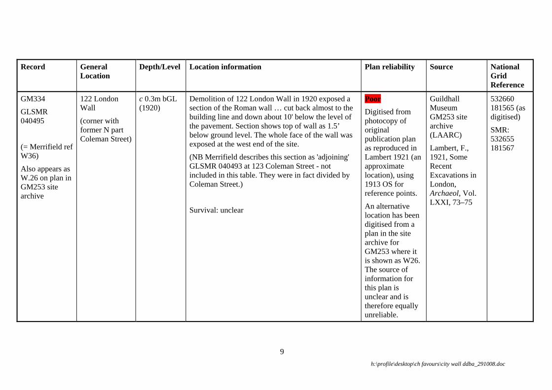
GM334
GLSMR 040495
(= Merrifield ref W36)
Also appears as W.26 on plan in GM253 site archive
122 London Wall
(corner with former N part Coleman Street)
c 0.3m bGL (1920)
Demolition of 122 London Wall in 1920 exposed a section of the Roman wall … cut back almost to the building line and down about 10' below the level of the pavement. Section shows top of wall as 1.5’ below ground level. The whole face of the wall was exposed at the west end of the site.
(NB Merrifield describes this section as 'adjoining' GLSMR 040493 at 123 Coleman Street - not included in this table. They were in fact divided by Coleman Street.)
Survival: unclear
Poor Digitised from photocopy of original publication plan as reproduced in Lambert 1921 (an approximate location), using 1913 OS for reference points.
An alternative location has been digitised from a plan in the site archive for GM253 where it is shown as W26. The source of information for this plan is unclear and is therefore equally unreliable.
Guildhall Museum GM253 site archive (LAARC)
Lambert, F., 1921, Some Recent Excavations in London, Archaeol, Vol. LXXI, 73–75
532660 181565 (as digitised)
SMR: 532655 181567
h:\profile\desktop\ch favours\city wall ddba_291008.doc
9

Record General Location
Depth/Level Location information Plan reliability Source National Grid Reference
GM108
GLSMR 040496
London Wall (N side, immediately west of Moorgate )
c 1.8m bGL
1.2m aGL in 1882, down to 2.4m bGL
Site notes for GM108 dated 1961 state that ‘At a depth of about 6ft from the modern pavement an irregular double course of Roman bonding tiles in yellow cement was seen’. This is the same piece as was observed in 1882 (see GLSMR 040496, Merrifield ref W35 below)
Note that the published grid reference and address details place this site location opposite the end of Coleman Street, while the site notes state that the masonry was observed immediately west of Moorgate.
Survival: It is unclear form the archive whether the masonry exposed survives in situ.
Poor GM108 archive consists of site notes with sketch plan only, dated 1961. However, this wall observation is shown (as W.25) on a plan in the site archive for GM253 and has been digitised from this. It is unclear what information this plan was based on.
Guildhall Museum GM108 and GM253 site archives (LAARC)
532700
181555 (amended)
h:\profile\desktop\ch favours\city wall ddba_291008.doc
10

Record General Location
Depth/Level Location information Plan reliability Source National Grid Reference
GLSMR 040496
(= GM108)
(= Merrifield ref W35)
London Wall, immediately west of Moorgate Street
1.2m aGL in 1882
Building work monitored by Loftus Brock in 1882 revealed c 43ft (13.11m) of the city wall lying beneath the street frontage. It was 9ft 2in (2.8m) thick (2ft (0.6m) of this being medieval thickening). A series of perhaps 6 supporting arches were noted on the inner face. These were semi-circular 2ft 6in (0.76m) wide, 1ft 11in (0.58m) deep, with piers 1ft 11in (0.58m) wide & lay c 15ft (4.55m) below ground level. The wall itself is recorded as standing 4ft (1.22m) above the surface (of the excavated site) & extending 'quite 8ft below'.
No plan Loftus Brock, E P, The Roman Wall of London at Moorgate, JBAA vol 38, 424–426,
RCHME 1928. Roy Comm Hist Momuments Engl, An inventory of the historical monuments in London: Vol 3, Roman London, 89
VCH. London, vol 1, p 61,
Lambert F. 1921, Some recent excavations in London, Archaeol Vol LXXI, 74
532691 181560
h:\profile\desktop\ch favours\city wall ddba_291008.doc
11

Record General Location
Depth/Level Location information Plan reliability Source National Grid Reference
MOO80
London Wall, near junction with Moorgate
Top of wall at c 9.5m OD
A GPO tunnel beneath the south carriageway of London Wall near its junction with Moorgate probably went through the brick foundations of the 15th-century Moorgate. A substantial brick wall was recorded: possibly the west wall of the 17th-century rebuild of Moorgate, as it projected north from the city wall, or a building fronting onto the road north of the gate.
Survival: unclear.
Poor Limits of brick wall as recorded in section digitised in relation to hand drawn approximate trench location on photocopy of contemporary OS map (MOO80 site archive, LAARC)
DUA MOO80 Level 2 site archive (LAARC)
532705 181565
Radar survey Junction of Moorgate & London Wall
c 1.8m bGL (measured from Fig 03 by MoLAS)
Approx. east–west radar anomaly corresponding to MoLAS prediction of S edge of the Moor Gate
Good
Digitised from hard copy Stratascan radar plot (1:500) on OS background
Stratascan assessment of Subtechnics’ utilities radar survey (Fig 03, July 2008)
532705 181550
h:\profile\desktop\ch favours\city wall ddba_291008.doc
12
Record General Location
Depth/Level Location information Plan reliability Source National Grid Reference
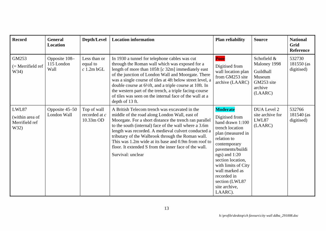
GM253
(= Merrifield ref W34)
Opposite 108–115 London Wall
Less than or equal to c 1.2m bGL
In 1930 a tunnel for telephone cables was cut through the Roman wall which was exposed for a length of more than 105ft [c 32m] immediately east of the junction of London Wall and Moorgate. There was a single course of tiles at 4ft below street level, a double course at 6½ft, and a triple course at 10ft. In the western part of the trench, a triple facing-course of tiles was seen on the internal face of the wall at a depth of 13 ft.
Poor Digitised from wall location plan from GM253 site archive (LAARC)
Schofield & Maloney 1998
Guildhall Museum GM253 site archive (LAARC)
532730 181550 (as digitised)
LWL87
(within area of Merrifield ref W32)
Opposite 45–50 London Wall
Top of wall recorded at c 10.33m OD
A British Telecom trench was excavated in the middle of the road along London Wall, east of Moorgate. For a short distance the trench ran parallel to the south (internal) face of the wall where a 3.6m length was recorded. A medieval culvert conducted a tributary of the Walbrook through the Roman wall. This was 1.2m wide at its base and 0.9m from roof to floor. It extended S from the inner face of the wall.
Survival: unclear
Moderate Digitised from hand drawn 1:100 trench location plan (measured in relation to contemporary pavements/buildings) and 1:20 section location, with limits of City wall marked as recorded in section (LWL87 site archive, LAARC).
DUA Level 2 site archive for LWL87 (LAARC)
532766 181540 (as digitised)
h:\profile\desktop\ch favours\city wall ddba_291008.doc
13

Record General Location
Depth/Level Location information Plan reliability Source National Grid Reference
AOP99
GLSMR085088–9
(within area of Merrifield ref W32)
London Wall
(near junction with Copthall Avenue)
11.80m OD (0.83m bGL).
Foundation continues below 8.60m OD.
Replacement of a large telephone manhole in the centre of the road re-exposed two sections across the Roman and Medieval city wall Both faces of the wall had been cut back by later intrusions (including the 1934 manhole*), except at the east end, where the outer (north) face of the wall was intact. This face was interpreted as a medieval refacing. At this location the wall was at least 2.6m wide.
*see also GM72
Survival is indicated beneath the floor of the manhole and immediately to the east and west of the recorded sections.
Accurate Trench and section surveyed by MoLAS to OS grid.
But note that as Section 1 is missing from the archive, the exact location of N face of wall within section at east end of trench is unclear. Photographic evidence suggests the face was c 0.2m from the northern limit of the recorded section location and it has been digitised as such.
Westman, A 1999 BT Hole in London Wall, EC1, An Archaeological watching brief, unpub MoL rep
MoLAS Geomatics original survey data
532780 181538 (as digitised).
h:\profile\desktop\ch favours\city wall ddba_291008.doc
14

Record General Location
Depth/Level Location information Plan reliability Source National Grid Reference
GM72
GLSMR 044360
London Wall
(near junction with Copthall Avenue)
c 3.7m bGL? (but see AOP99)
core of wall at c 3m bGL
In 1934 at a depth of 12ft 3in the back of the city wall was exposed and a ‘tunnel’ cut through it. The wall was just over 7 ft (2.13m) thick.
*see also AOP99
No Plan. GM72 archive contains no accurate site location.
Schofield & Maloney 1998
532785 181540
LON82
(within area of Merrifield ref W32)
London Wall, junction with Copthall Avenue
c 10.35m OD Opposite no. 55 and 57 London Wall.
Observations during work on a telephone manhole in London Wall street. A 2m–2.5m stretch of the Roman city wall was exposed. (N.B. Archive summary grid reference is wrong)
Survival: unclear
Good Digitised from LON82 1:100 site/section location plan (with OS refs) and 1:10 sections/elevations (LAARC)
DUA LON82 Level 2 site archive (LAARC)
532810
181530 (as digitised).
GM333
(= Merrifield ref W31)
London Wall, opposite Carpenters' Hall
1.6m bGL In 1905, a shaft was sunk on the outside face of the wall at this point. The wall, 4' thick, was encountered 5' 3" down. The base of the wall was 19' below the surface.
Survival: unclear
Poor Digitised from plan in Archaeologia 1906 article, related to copy of 1894 OS
Norman, P and Reader, F 1906, Recent Discoveries in connexion with Roman London, in Archaeologia LX pt 1, 171
532900 181515 (as digitised)
h:\profile\desktop\ch favours\city wall ddba_291008.doc
15

Record General Location
Depth/Level Location information Plan reliability Source National Grid Reference
WBH06 (part)
Blomfield Street
Junction of London Wall and Blomfield Street
0.8m bGL Eastern side of the junction of Blomfield Street and London Wall (TW water main replacement).
There was a fairly smooth/regular face to the north, although this may be the core exposed by robbing of the facing blocks.
Good Digitised from image of wall locations on OS mapping supplied by Compass Archaeology
Compass Archaeology communications and plan
h:\profile\desktop\ch favours\city wall ddba_291008.doc
16

Record General Location
Depth/Level Location information Plan reliability Source National Grid Reference
BLM87
GLSMR
041918
85 London Wall. Blomfield House, Junction of London Wall and Blomfield Street
c 9.30m OD (c3.2–3.25m bGL)
85–86 London Wall, 53 New Broad Street. Part of the external face of the city wall was recorded at the southern edge of the site in 1988. The observed, external face of the Roman wall includes the sandstone plinth, 4 ragstone courses and the first tile string course, but the core of the wall survived to a height above the second tile string course.
NB This puts the remains of the wall to the north of the scheduled area.
Survival: the city wall in the south face of current building survives in two arches in the south-west corner of site; it was destroyed in two others.
Moderate Digitised from BLM87 1:100 hand drawn trench and section location plan, site grid plan referenced to OS, and City wall projection plan (LAARC)
A note in the site archive suggests that there is a fairly large degree of error in the plotting of the wall in relation to the site grid.
DUA Level 2 site archive for BLM87 (LAARC)
532950
181505 (as digitised)
h:\profile\desktop\ch favours\city wall ddba_291008.doc
17

Record General Location
Depth/Level Location information Plan reliability Source National Grid Reference
CAP86
Capel House, 54-62 New Broad Street
Base of plinth recorded at 10 to 10.66m OD; only few courses survive
The external (north) face of the city wall formed the southern boundary of the site (immediately north of All Hallows on the Wall). The wall itself was not observed in the excavation trenches but within test pits dug prior to demolition. The wall was recorded in TP 1 to the west of the church (base of wall at 10m OD), TP 3 and 4 on east side of church (base at 10.25 and 10.66m OD) and TP 2 north of vestry
Survival: a survey in 1991-2 found that the outer face of the wall is visible in a basement area of 54–62 New Broad Street for a distance of c 23m west and c 24m east of bastion 11 (the vestry of All Hallows) and part of the bastion fabric is also visible.
Good Digitised from CAP86 1:100 site & trench location and 1:10 elevations, best fitted to OS using church of All Hallows on the Wall (LAARC)
DUA CAP86 Level 2 site archive (LAARC)
533006 181494
GLSMR 041922
(= Merrifield ref W29)
London Wall, All Hallows Churchyard (west of church)
The city wall forms the northern boundary of the churchyard. When the external face of the city wall was uncovered in 1905, Roman work was found remaining to a height of 12 ft (i.e. to about contemporary ground level). Above the plinth were 4 courses of squared ragstone, a triple bonding course, 5 courses of ragstone, a second triple bonding course, 6 courses of ragstone, a double bonding course, and 3 more courses of ragstone. Below the plinth, a brick-lined culvert passed through the foundation. It lay in a hollow depression, possibly a stream bed, apparently pre-dating the city ditch.
Moderate Digitised from published plan dated 1906 (pl XXV) in Archaeologia vol LX pt 1, using 1894 OS map as reference.
Norman P & Reader FW. 1906, Recent discoveries in connexion with Roman London, Archaeologia vol LX pt 1, 207–210 and pl XXV
533000 181492
h:\profile\desktop\ch favours\city wall ddba_291008.doc
18

Record General Location
Depth/Level Location information Plan reliability Source National Grid Reference
GM332
GLSMR 041924–5
(= Merrifield refs B11, W28)
All Hallows on the Wall church, London Wall (vestry)
Excavation in 1905 by the Society of Antiquaries revealed the vestry of All Hallows Church to have its foundations set on a bastion of the city wall. It was 19ft (5.79m) in diameter & projected 15ft (4.57m) from the face of the wall. It survived to a height of 8ft, of which 3ft extended below the plinth of the city wall. Its N edge overlay the S edge of the Roman ditch.
(SMR grid ref (533028 181496) is not accurate – c 6m from bastion)
This work also revealed the lower part of the city wall, which forms N boundary of church/churchyard. The wall consisted of he plinth, with four courses of squared ragstone and a triple bonding course.
Good Digitised from published plan dated 1906 (Archaeologia vol LX pt 1, pl XXV), relative to extant vestry of All Hallows church on modern OS mapping.
Norman P & Reader FW., 1906, Recent discoveries in connexion with Roman London, Archaeol vol LX pt 1, 200 ff
Norman, P, & Reader, FW, 1912, Further discoveries relating to Roman London, Archaeol vol LXIII, p 271 ff
Centre of Vestry / bastion on OS = 533021 181491
h:\profile\desktop\ch favours\city wall ddba_291008.doc
19

Record General Location
Depth/Level Location information Plan reliability Source National Grid Reference
GLSMR 041926
(= Merrifield ref W27)
London Wall, East of All Hallows Church
Building work monitored by P Norman & FW Reader in 1905 revealed a small portion of the Roman fabric of the city wall 45ft (13.72m) E of All Hallows church. The plinth & 2 courses of squared ragstone were exposed. (see also 041923)
Moderate Digitised from published plan dated 1906 (pl XXV) in Archaeologia vol LX pt 1, using 1894 OS map as reference.
Norman P & Reader FW. 1906, Recent discoveries in connexion with Roman London, Archaeologia vol LX pt 1, 211-212 and pl XXV
533050 181482 (as digitised)
h:\profile\desktop\ch favours\city wall ddba_291008.doc
20

Record General Location
Depth/Level Location information Plan reliability Source National Grid Reference
WOE94
GLSMR 044079
22–24 Wormwood Street
c 13.24m OD The Roman city wall survived to its full width through the north side of the basement of 23–24 Wormwood Street, retained by a 1 brick thick wall.. The top of the Roman masonry was exposed in 24 Wormwood Street.
The north basement wall of 22 Wormwood Street had been constructed on the line of the city wall in the post-medieval period out of reused stone from the wall. This wall was recorded by means of rectified photography.
Survival: city wall preserved and covered over in basement.
Good There is no site location or plot of the wall in the archive. In the absence of such information, OS values of photo targets on back wall of property (from MoLAS survey data archive sheet, (LAARC)) were digitised, to give N face of wall, and offset 2.53m to the south to provide alignment across Nos. 23–24 Wormwood Street.
MoLAS WOE94 Level 2 site archive (LAARC)
Sankey, D 1998, 22–24 Wormwood Street, An archaeological watching Brief, unpub MoL rep
533165 181460
h:\profile\desktop\ch favours\city wall ddba_291008.doc
21

Record General Location
Depth/Level Location information Plan reliability Source National Grid Reference
WOD86
GLSMR 044244 & 041927
See also WOE94
22 Wormwood Street
Localised area of clay and flint foundation recorded at 11.82m OD
The northern face of a post-medieval wall of reused ragstone, forming the north cellar wall apparently conformed to the alignment of the external face of the City wall. However, the only surviving evidence of the original structure was a localised patch of clay and flint foundation material.
Moderate (but no actual survival of wall superstructure )
Line of post-medieval rebuild digitised from WOD86 1:200 site /section location (manually plotted onto OS 1:1250 tracing) and 1:20 elevation (LAARC)
Sankey D, 1994 22 Wormwood Street, An archaeological evaluation (unpub MoL rep)
MoLAS Level 2 site archive for WOD86 (LAARC)
533170 181455
WOM94
GLSMR 044147, 044149–50, 044441, 044437
20–21 Wormwood Street, 105–107 Bishopsgate
20–21 Wormwood Street, 105–107 Bishopsgate.
The City wall had been entirely removed from 20–21 Wormwood Street. At no. 21 a post-medieval masonry wall on the north perimeter had replaced it.
Further work under this site code at 105–107 Bishopsgate in 1996 revealed no trace of the City Wall.
No wall recorded Sankey D, 1996 20 and 21 Wormwood Street, An archaeological evaluation, unpub MoL rep
533180 181455
h:\profile\desktop\ch favours\city wall ddba_291008.doc
22

Record General Location
Depth/Level Location information Plan reliability Source National Grid Reference
WBH06 (part)
Bishopsgate
Wormwood street/ Bishopsgate junction
1.1–1.4m bGL (more heavily truncated elsewhere)
Western carriageway of Bishopsgate, opposite No. 105/106 (TW water main replacement).
To N: wall probably from 17th-century gatehouse. ‘start of the masonry was just about’ at the N edge of the SAM mapping (G. Potter, CA, pers comm).
To S: wall of medieval/Roman city wall or gate.
Good Digitised from image of wall locations on OS mapping supplied by Compass Archaeology
Compass Archaeology summary and plan
(approx. NGR 533206 181450 – as digitised)
GLSMR 041929/02
Bishopsgate 1.5m bGL NW corner of junction of Bishopsgate and Wormwood Street
A mass of ragstone rubble c 6 ft 6 in square, at a depth of 5ft (1.5m). This extended to a depth of 10ft (3.0m) below the surface. It contained fragments of Roman tile & was apparently carefully faced on its S side. This rested on a puddling of flint & clay, c 10 ft square (whole of manhole being observed). The remains probably formed part of the S face of a gatehouse of the Roman Bishopsgate & projected c 20ft (6m) inside (S of) the city wall.
Poor Digitised from Norman & Reader’s published Fig 3 sketch plan (Archaeologia Vol LX pt 1, 186), but this does not tally with accompanying text, & is difficult to locate to street/building lines
Norman, P, & Reader, FW, 1906 Archaeologia Vol. LX. pt 1, 184–187
533205 181445 (as digitised)
h:\profile\desktop\ch favours\city wall ddba_291008.doc
23

Record General Location
Depth/Level Location information Plan reliability Source National Grid Reference
BTB89
GLSMR 041929
Bishopsgate c 12.75m OD Bishopsgate, north of junction with Wormwood Street & Camomile Street.
Watching brief during British Telecom tunnelling by DUA revealed foundations of Kentish rag & clay with mortared ragstones, recorded in section. These were thought to represent part of the Roman Bishopsgate.
Good Site surveyed by DUA to OS grid.
Locations of wall foundations recorded in section digitised from 1:10 sections in relation to hard copy 1:100 site plan tied to OS.
DUA BTB89 Level 2 site archive (LAARC)
533208 181442 (S)
533217 181453 (N) (as digitised)
GLSMR 041929/01
Bishopsgate 0.9m bGL Excavation "on the N side of" 108 Bishopsgate by WC Edwards in 1921 revealed ‘Roman masonry, apparently a wall c 5ft (c 1.5m) thick, at a depth of 3ft from the surface. This ran N–S (ie at right angles to the city wall) & may have formed part of the gateway’
No plan Edwards, 1922 (TransLAMAS NS IV, 332)
SMR: 533220 181450 (minimum 10m)
h:\profile\desktop\ch favours\city wall ddba_291008.doc
24

Record General Location
Depth/Level Location information Plan reliability Source National Grid Reference
CMI00 & KPH05
GLSMR 085135
Kempson House and Bishops(gate) House
Possible city wall: 11.42m OD
25–37 Camomile Street, 106–126 Bishopsgate. Site centre: NGR 533250 181450.
CMI00: two test pits in the SE and SW corners of the underground car park confirmed that no trace of the City wall, or its robbing in antiquity, survived. The City wall, therefore, must originally have been situated either along the southern edge of the present buildings or even further to the S, outside the [CMI00] site boundaries.
KPH05: In one of two test pits along the S frontage of the site a possible Roman wall foundation survived beneath the modern truncation. The remains continued beyond the N and E limits of excavation, but not in a westerly direction as might perhaps be expected for the Roman City wall foundation. It may therefore be either an isolated deep level foundation for the City wall, or part of an earlier structure.
Good (good location, but poor identification)
MoLAS digital survey data
MoLAS KPH05 digital survey data
Tyler, K. Evaluation at Kempson House, unpub MoL rep
KPH05 533260 181425 (as digitised)
h:\profile\desktop\ch favours\city wall ddba_291008.doc
25

Record General Location
Depth/Level Location information Plan reliability Source National Grid Reference
GM349
GLSMR 041932–3
27–33 Camomile St, junction with Outwich St
Demolition work monitored by JE Price in 1876 revealed a stretch of the city wall c 88ft (46.82m) in length. It was 8ft (2.44m) thick. It was destroyed above the plinth.
Also a semi circular bastion attached to the city wall. This was 20ft (6.10m) in diameter & projected 14ft 9in (4.50m) from the walls face. Uncertainty exists regarding the bastion’s exact location.
Poor Digitised from photocopy of RCHM 1928 plan, using contemporary OS for reference points
Price JE, 1880, On a bastion of London Wall, or, Excavations in Camomile Street Bishopsgate, London, 23–25, Fig. reproduced in RCHM, 1928, London, III, Roman London, 86, 101
SMR: 533274 181421
HSD89
GM288
GLSMR 041935
58–60 Houndsditch
Foundation of wall at 12.03m OD.
Wall survives to a maximum height of 4m in places
HSD89: The Roman city wall was exposed running along the SW edge of the site: the stones of the outer face were cut away by later cellaring, leaving only the core. The surviving portion was 5.2m long and 4m high and is to be preserved.
GM288: Part of the city wall forming the rear (S) of 58–60 Houndsditch and dividing it from the graveyard of St Martin Outwich was recorded by P Norman and F W Reader in 1905, again in 1926. In 1926 the bottom of the plinth was seen 8ft 4in. below street level. The fragment of wall stood in 1905 to a height of 14ft 6in. above the base of the plinth. The site records for 1926 could not be located.
Accurate
Digitised from HSD99 1:100 site plan/section location (with survey points referenced to OS) and 1:200 plan showing City wall (LAARC)
DUA, HSD99 site archive (LAARC)
Site centre: NGR 533320 181400
SMR: 533293 181412
h:\profile\desktop\ch favours\city wall ddba_291008.doc
26

Record General Location
Depth/Level Location information Plan reliability Source National Grid Reference
WHB06 (part) Goring Street
Goring Street c 0.4–0.6m bGL (truncated more deeply elsewhere)
(TW water main replacement).
As this is well to the east of the Crossrail works, only the depth is directly relevant .
Good Digitised from image of wall location on OS mapping supplied by Compass Archaeology
Compass Archaeology summary and plan
Approx. 533380 181330
h:\profile\desktop\ch favours\city wall ddba_291008.doc
27

6.1 Abbreviations aGL above ground level
bGL below ground level
DUA Department of Urban Archaeology (Museum of London)
GLSMR Greater London Sites and Monuments Record
OS Ordnance Survey
LAARC London Archaeological Archive and Research Centre
LAMAS London and Middlesex Archaeological Society
RMLEC Roman and Medieval London Excavation Council
MoLAS, Audit of the City Wall Cohen. N, & Hill, J, 2005, The London City Wall, unpub rep for Corporation of London
RCHM Royal Commission of Historic Monuments, Roman London Vol 3
Schofield & Maloney 1998 Schofield, J, with Maloney, C (eds), 1998 Archaeology in the City of London, 1907–1991: a guide to records of excavations by the Museum of London and its predecessors, Archaeol Gazetteer ser 1, MoL
Shepherd 1998 Shepherd, J D, 1998a Post-war archaeology in the City of London, 1946–1972: a guide to records of excavations by Professor W F Grimes held by the Museum of London, Archaeol Gazetteer ser 3, MoL
h:\profile\desktop\ch favours\city wall ddba_291008.doc
28

GM253GM108
W26
LO26J_26323
anomaly_No2
GM334
AOP99LON82
MOO80
LWL87
LO26P
LO32
26323
Salisbury House
LONDON WALL
MO
OR
GA
TE
Telephone Exchange
CIRCUS
Britannic House
FINSBURY
Station
Bank
Gate
House
Moorgate
Moor
Chambers
Tower
14.0m
12.5m
13.5m
13.4m
12.8m
Guildhall
Bandstand
(School of B
usi
ness S
tudie
s)
Girdlers' Hall
Coleman Street Bldgs
Moorfields Highwalk
Place
Underground Railway
Andre
wes
London G
uild
hall
Univ
ers
ity
Chartered Accountants
PH
Institute of
BM 13.25m
CIR
CU
S P
LA
CE
AVENUE
FO
RE
ST
RE
ET
MO
OR
FIE
LD
S
CO
LE
MA
N S
TR
EE
T
City
Yard
11
115
118
Andrewes Highwalk
Bass
ishaw
Hig
hw
alk
118a
Transport)
7 to 11
Ward Bdy
Justice
St Alphage Highwalk
(London
5
4
2 3
Posts
Alb
ion
3 to 6
16
87
85
36
80
45
12
55
30 to 3
4
8
10
43
56 to 6
0
48 to 5
4
101 to 1
09
49
55 to 5
9
150 to 168
94
54 to 65
14 to 2
4
9
25
84
20 t
o 3
0
91to
95
21
20
40
31
65
137
67
35
74
64
72
46
30
28
51
53
120
34
73
63
1
41
42
7
83
44
141
81
17
19
6
Keats Place
Sub
LB
BASINGHALL AVENUE
13.1m
TCBs
BPs
FB
D Fn
Nun Court
St. Alpage
SD
MOOR PLACE
Great Swan Alley
CO
PT
HA
LL A
VE
NU
E
TCB
LANGTHORN COURT
PC
PH
House
Bank
Bank
TCB
8
40
67
20 t
o 3
0
4
House
TCBBank
42
2
54 to 65
80
6455
3
2FB
Bank
Bank
PH
FORE STREET
Bank
16
Bank
2
Bank
41
Bank
PH
Bank
Bank
2
21
12.5m
16
PH
11
55 to 5
9 25
LB
© MoLAS 2008
0 100m
City wall DDBA: west
Based upon the Ordnance Survey mapping with the permission ofthe Controller of Her Majesty's Stationery Office © Crown Copyright.
Unauthorised reproduction infringes Crown copyright and may lead
to prosecution or civil proceedings. City of London 100023243 2008.
Legend
Scheduled Monuments_230807
CITY WALL RECONSTRUCTION 2008
CITY WALL Observations
RELIABILITY
ACCURATE
GOOD
MODERATE
POOR
BTB89
GM332
WOE94
GLSMR041922
BLM87
GM333
GLSMR041929_02
GLSMR041926
COMPASS_WormwoodSt
CAP86
COMPASS_Blomfield_St
LO26N
LO26A
Priory and Hospital
of
St Mary of Bethlehem
LONDON WALL
CIRCUS
London Wall Buildings
FINSBURY
Bank
Postern
Site of
Broad Street House
(Founded AD 1247)
Capel House
Hope Square
House
Tennis Court
Pinners Hall
14.4m
13.4m
15.5m
12.5m
Wall
Bandstand
BPs
Carpenters' Hall
Hotel
Swedbank
Church
Clerk's Place
BroadBowling Green
PH
New Broad Street
New Broad St
BM 13.82m
The Arcade
Liverpool St Station
CIR
CU
S P
LA
CE
Stree
t
LIVERPOOL STREET
OLD
BR
OA
D S
TR
EE
T
NEW BROAD STREET
BLO
MFIE
LD S
TR
EET
Petty France
BLO
MFIE
LD S
T
WORMWOOD STREET
11
(site of)
Ward Bdy
Bishopsgate ChurchyardBoston
St Botolph without
All Hallows on the Wall
Posts
3
5
23
13
10
1
52 to 5
7
12
84
21
34 to 37
19
25
24
75
17
26
9 to 1
9
87 to 9
1
81 to 9
1
76 to 8
0
80
99
14
20
28
22
1 to 5
27 to 34
105 to 1
08
73
3.5
54 to 65
9
5 to 7
8
6
35
2
29
33
23 to 25
18
15
54 to 62
27
7
46
16
8890
45
42
55
70
53
47
77
85
100
64
86
74
50
82
72
101
31
32
69
63
30
4
Alderman's Walk
St B
oto
lph's
(LRT)
LB
SL
SB
12.8m
AVENUE
TCBs
El Sub Sta
BM 13.10m
Ps
Fn
TH
RO
GM
OR
TO
N A
VE
NU
E
FB
D Fn
22 to
Aust
in F
riars
Passa
ge
BROAD STREET
TCB
GREAT WINCHESTER STREET
Aldermans
BP
White Hart
Bank
19
PH
1418
Bank
33
Pinners Hall
3
Ps
10
20
OLD
BR
OA
D S
TR
EE
T
24
Ps
105 to 1
08
24
1
23
FB
42
75
Bank
7
1
Ward Bdy
21
14
Bank
26
8
10
25
PH
13
PH
26
LONDON WALL
11
15
25
Bank
TCB
Ps
15
20 22
House
LB
11
2
2
64
21
1
SL
Posts
LB
1
19
6
Ba
nk
Ward
Bdy
Bank
12
1916
PH
PH
23
1
25
18
(site of)Posts
17
13
21
2
14.4m
2
LB
© MoLAS 2008
0 100m
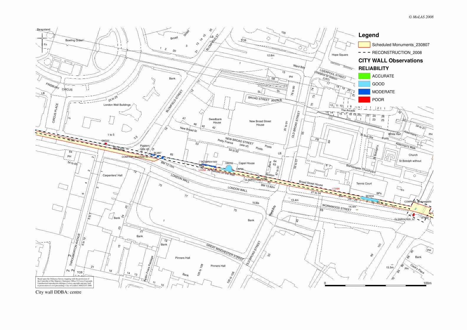
City wall DDBA: centre
Based upon the Ordnance Survey mapping with the permission ofthe Controller of Her Majesty's Stationery Office © Crown Copyright.
Unauthorised reproduction infringes Crown copyright and may lead
to prosecution or civil proceedings. City of London 100023243 2008.
Legend
Scheduled Monuments_230807
RECONSTRUCTION_2008
CITY WALL Observations
RELIABILITY
ACCURATE
GOOD
MODERATE
POOR

BTB89
GM349
WOE94
HSD89
GLSMR041929_02
KPH05
COMPASS_WormwoodSt
COMPASS_GoringSt
LO26N
LO26M
LO26L
Staple Hall
Bank
Bethlehem Gate
Broad Street House
Railway
Underground Railway
Underground
House
Tennis Court
Cutlers
Camomile Court
14.8m
13.4m
14.4m
15.8m
15.5m
16.1m
15.7m
BPs
Chatsworth
Stone House
Premier Place
Church
Clerk's Place
Court
CU
TLE
R
PH
HOUNDSDITCH
Exchange
Exchequer
BM 16.37m
BM
16.
14m
The Arcade
Bevis Marks
ST HELEN'S PLACE
STREET
OUTW
ICH S
TR
EET
DEVONSHIRE SQUARE
OLD
BR
OA
D S
TR
EE
T
BIS
HO
PS
GATE
WORMWOOD STREET
11
Air
(site of)
Arc
ade
115
114
119
113112
117
117 to 119
Library
Ward Bdy
Bishopsgate ChurchyardBoston
St Botolph without
1
Posts
7
5
12
50
3
13
35
1 to 9
1 to
6
23
52 to 5
7
84
4
34 to 37
138
66 to
70
1 to 3
37 to 41
81 to 9
1
87 to 9
1
80
99
14
55
31 to 36
121
27 to 3487 to 90
152
17
77 to 84
60 to
68
57 to 60
44
25
952
to 5
8
2
26
16
22
24
144
142
33
140
128 to 1
40
18
12 to 20
120
123
15
154
63
8890
45
38
6
8
19
3a
148
46
10
61
86
60
82
101
20
32
69
78
146
21
64
Alderman's Walk
St B
oto
lph's
LB
Sto
ne H
ous
e C
t
D Fns
15.2m
El Sub Sta
BM 16.23m
Wre
stle
rs C
t
Fn
Pond
Cavendish
FB
22 to
BARBO
N A
LLEY
DEVONSHIRE
Aldermans
CLO
THIE
R S
TREET
White Hart
16
10
1
38
5
Bank
6
16
25
5
1
3
El Sub Sta
9
22
PH
16
Bank
5
Bank
5
26
PH
24
23
Ward
Bdy
PH
2
15LB
6
FB
63
10
17
Ba
nk
Ward Bdy
6
17
35
10
8
Bank
50
33
7
55
PH
1813
4
PH
11
7
12
25
17
15
1
7
9
7
3
33
PH
33
8
© MoLAS 2008
0 100m
City wall DDBA: east
Based upon the Ordnance Survey mapping with the permission ofthe Controller of Her Majesty's Stationery Office © Crown Copyright.
Unauthorised reproduction infringes Crown copyright and may lead
to prosecution or civil proceedings. City of London 100023243 2008.
Legend
Scheduled Monuments_230807
RECONSTRUCTION_2008
CITY WALL Observations
RELIABILITY
ACCURATE
GOOD
MODERATE
POOR

Liverpool Street: Method Statement for Verizon works at Old Broad Street in relation to the Scheduled Monument – City Wall (LO26N)
Document uncontrolled once printed. All controlled documents are saved on the CRL Document System
© Crossrail Limited UNCONTROLLED
Appendix D E-Mail Correspondence relating to radar surveys

1
Mike Court
From: Simon Haddrell [[email protected]]Sent: 01 August 2008 09:16To: Elsden, NickSubject: RE: City Wall, London
Nick, The original survey in the west was inconclusive, with the same conditions being expected in the east this would suggest that any radar work here would give similar results to that in the first area. This is of course based on the assumption that the wall did pass though the survey area in the west. Regards Simon ______________________________________ Simon Haddrell BEng.(Hons) AMBCS PIFA Project Officer STRATASCAN Ltd
Vineyard House Upper Hook Road Upton Upon Severn Worcestershire WR8 0SA UK Tel: +44(0)1684 592266 Mob: +44(0)7966 046380
Fax: +44(0)1684 594142 www.stratascan.co.uk
Registered Archaeological Organisation with the Institute of Field Archaeologists Member of The Survey Association Member of EuroGPR Association ISO 9001.2000 Quality Assurance Accredited ISO 14001.2004 Environmental Management Accredited Achilles UVDB Registration No. 80959
From: Elsden, Nick [mailto:[email protected]]
Sent: 31 July 2008 14:10 To: Simon Haddrell
Subject: RE: City Wall, London thanks for you explanation on the phone, Simon. As this was the last of the three questions in the document we sent you at the beginning, I would be grateful if you could just put in writing for us and our client, Crossrail, the conclusion that we came to on e the phone. I.E. that it seems unlikely that a radar survey of the second half of the area, assumed to have similar conditions to the first, would yield significantly greater results than the first half (or words to that effect). Thanks, Nick
Nicholas Elsden Project Officer\Senior Archaeologist Museum of London Archaeology Service Mortimer Wheeler House 46 Eagle Wharf Road London. N1 7ED Tel: 020 7410 2282 Fax: 020 7410 2201

2
Email: [email protected] www.molas.org.uk
Now available, The London Guildhall; an archaeological history of a neighbourhood from early medieval to modern
times: generously funded by the City of London Corporation, evidence from archaeological excavations is combined
with historical and architectural analysis to create a major integrated history of the London Guildhall, the home of the City of London’s government (MoLAS Monogr Ser 36 (2-part set); £65)
� Before printing, think about the environment
From: Simon Haddrell [mailto:[email protected]]
Sent: 31 July 2008 13:51 To: Elsden, Nick
Subject: RE: City Wall, London
Hi Nick, Due to the lack of evidence in this survey for the city wall I think further radar surveys over this area will give very limited results. As for the section to the east I think it would be safer to make an assessment from a DBA. If the wall crosses the road and is still intact it should be possible to see this through the services. I would also suggest a low frequency antenna to see as deep as possible if the survey is for archaeology exclusively. I hope this helps Regards Simon ______________________________________ Simon Haddrell BEng.(Hons) AMBCS PIFA Project Officer STRATASCAN Ltd
Vineyard House Upper Hook Road Upton Upon Severn Worcestershire WR8 0SA UK Tel: +44(0)1684 592266 Mob: +44(0)7966 046380
Fax: +44(0)1684 594142 www.stratascan.co.uk
Registered Archaeological Organisation with the Institute of Field Archaeologists Member of The Survey Association Member of EuroGPR Association ISO 9001.2000 Quality Assurance Accredited ISO 14001.2004 Environmental Management Accredited Achilles UVDB Registration No. 80959
From: Elsden, Nick [mailto:[email protected]]
Sent: 31 July 2008 13:33 To: Simon Haddrell
Cc: Dennis, George; Claire Hicks
Subject: RE: City Wall, London Importance: High Dear Simon, this last item has now become urgent, as Crossrail have only a limited time in which to commission future archaeological fieldwork on the basis of these results. I would be grateful if you could either email me or phone me (020 7410 2282) today or tomorrow. Regards, Nick

3
Nicholas Elsden Project Officer\Senior Archaeologist Museum of London Archaeology Service Mortimer Wheeler House 46 Eagle Wharf Road London. N1 7ED Tel: 020 7410 2282 Fax: 020 7410 2201 Email: [email protected] www.molas.org.uk
Now available, The London Guildhall; an archaeological history of a neighbourhood from early medieval to modern
times: generously funded by the City of London Corporation, evidence from archaeological excavations is combined
with historical and architectural analysis to create a major integrated history of the London Guildhall, the home of the City of London’s government (MoLAS Monogr Ser 36 (2-part set); £65)
� Before printing, think about the environment
From: Elsden, Nick
Sent: 29 July 2008 13:55 To: 'Simon Haddrell'
Cc: Dennis, George; 'Claire Hicks' Subject: RE: City Wall, London
Dear Simon, thank you for the 'graphic report'. However, it did not answer the third question in the assessment purpose' document, which was:
• Do these results suggest that any future radar surveys (archaeologically focused – to locating the
wall) are likely to be either unproductive or productive ?
a) in this section previously surveyed ? (may not be required, depending on the results of this
assessment).
b) in the sections to the east of the existing survey, where the density of services is likely to be similar ?
This is effectively the most important point, as we need to decide whether there is any point in conducting further radar surveys to find the gaps or low points in the surviving sections of the wall (where new services can be passed). Clearly part of the answer to the above lies in whether the surveys need to be 'tuned' to different settings to locate masonry from those required to locate services - could you tell me if this is the case, or not ? Many thanks, Nick
From: Simon Haddrell [mailto:[email protected]] Sent: 25 July 2008 16:45
To: Elsden, Nick
Subject: City Wall, London
Nick, Please find the results attached for the City wall, London. Regards Simon ______________________________________ Simon Haddrell BEng.(Hons) AMBCS PIFA Project Officer

4
STRATASCAN Ltd
Vineyard House Upper Hook Road Upton Upon Severn Worcestershire WR8 0SA UK Tel: +44(0)1684 592266 Mob: +44(0)7966 046380
Fax: +44(0)1684 594142 www.stratascan.co.uk
Registered Archaeological Organisation with the Institute of Field Archaeologists Member of The Survey Association Member of EuroGPR Association ISO 9001.2000 Quality Assurance Accredited ISO 14001.2004 Environmental Management Accredited Achilles UVDB Registration No. 80959
________________________________________________________________________
This e-mail has been scanned for all viruses by Star. The
service is powered by MessageLabs. For more information on a proactive
anti-virus service working around the clock, around the globe, visit:
http://www.star.net.uk
________________________________________________________________________

Liverpool Street: Method Statement for Verizon works at Old Broad Street in relation to the Scheduled Monument – City Wall (LO26N)
Document uncontrolled once printed. All controlled documents are saved on the CRL Document System
© Crossrail Limited UNCONTROLLED
Appendix E Archaeological Watching Brief & Evaluation – Utilities trial trenches, Liverpool Street and London Wall

CROSSRAIL ARCHAEOLOGICAL WATCHING BRIEF & EVALUATION Utilities trial trenches, Liverpool Street and London Wall November 2009
CONFIDENTIALITY
This document contains proprietary information which shall not be reproduced without the permission of the CRL Chief Executive
Document History (MOLA Internal): Version: Date: Prepared By: Checked By: Approved By: Version History 1.0 24.11.09 David Sankey, Adrian
Miles, Nicholas J Elsden Nicholas J Elsden George Dennis First Issue
2.0 10.03.10 Nicholas J Elsden – George Dennis Comments from Claire Wright addressed
Crossrail Ltd 25 Canada Square Canary Wharf LONDON E14 5LQ Tel: 020 3229 9100 Fax: www.crossrail.co.uk
Museum of London Archaeology© Museum of London, 2009
Mortimer Wheeler House, 46 Eagle Wharf Road, London N1 7ED tel 0207 410 2200 fax 0207 410 2201
email [email protected]

Crossrail Liverpool Street and London Wall watching brief © MOLA 2009
Contents Executive Summary 1
1 Introduction 2 1.1 Site background 2 1.2 Planning and legislative framework 2 1.3 Summary of Previous Crossrail Studies 3 1.4 Origin and scope of the report 4 1.5 Aims and objectives 5
2 Topographical and historical background 6 2.1 Roman Period (AD 50–450) 6 2.2 Medieval Period (AD 450–1540) 6 2.3 Post-medieval (AD 1540–1900) 6 2.4 Archaeological Potential within 1.5m of ground level 7
3 The watching brief 8 3.1 Methodology 8 3.2 Results of the watching brief 10 3.3 Summary of results 18
4 Conclusions 20 4.1 City wall 20 4.2 Burials in Liverpool Street 21 4.3 Significance of the data 21 4.4 Publication and archiving 23
5 References 23
6 NMR OASIS archaeological report form 25
Figures 27 Annex 1: Additional figures from city wall DDBA (Crossrail 2008a)
i
p:\multi\1051\xrf09\field\archaeology wb report liv mor v2 100310.doc
Crossrail Liverpool Street and London Wall watching brief © MOLA 2009
Figures Fig 1 Site location
Fig 2 Trench location (west)
Fig 3 Trench location (east)
Fig 4 Plan of city wall in MOR18
Fig 5 Section across city wall E–W in Trench MOR18
Fig 6 Section across city wall W–E in Trench MOR18
Fig 7 MOR18, looking east
Fig 8 Plan of city wall at the junction of London Wall and Blomfield Street (in Trenches LIV16 and LIV26)
Fig 9 Vertical view of city wall in LIV16, looking north
Fig 10 City wall in LIV26, looking north
Fig 11 Plan of cellar walls in LIV19
Fig 12 Revised reconstruction of the city wall
See also Annex 1 for figures from the city wall DDBA (Crossrail 2008a)
ii
p:\multi\1051\xrf09\field\archaeology wb report liv mor v2 100310.doc

Crossrail Liverpool Street and London Wall watching brief © MOLA 2009
Executive Summary Ten 1.5m-deep engineer’s trial trenches to trace existing utilities within streets at London Wall, Old Broad Street and Liverpool Street, in the City of London were monitored in a watching brief commissioned by Crossrail, and conducted by MOL Archaeology. The trial trenches selected for monitoring were those across the line of the Roman and medieval city wall, a Scheduled Monument (LO26N and LO26P), and those within the former burial ground of the hospital of St Mary Bethlem, where human remains have been discovered previously. This monitoring serves as both an archaeological watching brief, and as the Required Evaluation for the city wall, as set out in a Scheduled Monument Deed under the Crossrail Act (2008). A further aim was to ensure that the works did not damage the Scheduled Monument, should the city wall be encountered. Remains of the city wall were recorded in London Wall (road) east of the junction with Moorgate. A second fragment of the city wall was found in London Wall south of the junction with Blomfield Street. Protective materials were installed before the trenches were reinstated. In general these results substantially confirm the reconstruction of the line of the city wall produced in 2008 for the Crossrail utility works (DDBA), which differs from the English Heritage Schedule mapping in the area around Blomfield Street. There is a minor change in the reconstruction between Moorgate and Blomfield Street, illustrated in the accompanying figures. These observations will inform design of the proposed utility diversions that will be required in advance of the main construction phase for Crossrail. In particular, although negative results should be used with caution (because of the limited depth and area of the trenches), the trenches at the junction of London Wall and Blomfield Street do appear to indicate that there may well be a considerable area at that location where 1.5m-deep utility diversions would not disturb the Scheduled Monument. The two sections of the city wall which were found support (and slightly refine) the 2008 reconstruction (Crossrail 2008a), allowing it to be used with greater confidence in designing utility diversions parallel with the city wall in this area. Disarticulated human bone was observed in two trenches in Liverpool Street. One group may represent the top of a deposit containing burials at greater depths than those reached in the trial trench, the other was found amongst modern overburden. Both have been reburied in the respective trenches. Remains of 18/19th-century cellars were recorded beneath modern services in Old Broad Street, near the junction with London Wall. The limited amount of human remains encountered in Liverpool Street should be treated with caution. Whilst it does demonstrate the extensive modern disturbance within c 1.5m of ground level already known from previous work in Liverpool Street, it should be expected that more extensive, or deeper, trenches for utility diversions have a high potential to encounter further localised areas of dense burials.
1
p:\multi\1051\xrf09\field\archaeology wb report liv mor v2 100310.doc

Crossrail Liverpool Street and London Wall watching brief © MOLA 2009
1 Introduction
1.1 Site background A new station is to be constructed in the Liverpool Street/Moorgate area of the City of London for the Crossrail project. In order to construct the station, a large number of existing utilities will have to be diverted in advance of construction, and utilities trial trenches were conducted to inform the plan for those diversions. This report describes the results of an archaeological watching brief on utilities trial trenches in the Liverpool Street–Moorgate area, at London Wall (street), Liverpool Street, Blomfield Street, and Old Broad Street (Fig 1), hereafter called the site. The centre of the site is at OS National Grid Reference 532893 181531. The site code is XRF09. The trial trenches were monitored between 9th May and 1st August 2009. The Roman and medieval city wall is often referred to as London Wall; but since this is also a modern road name, the historic structure is referred to in this report as the city wall, reserving ‘London Wall’ for the road. The trial trenches in London Wall, Blomfield Street, and Old Broad Street lie across the line of the Roman and medieval city wall, a Scheduled Monument (LO26N and LO26P). This work was conducted in accordance with a Scheduled Monument Deed under the Crossrail Act (2008), which replaces Scheduled Monument Consent (see 1.2). The archaeological survival data obtained during this monitoring also forms the Required Field Evaluation as set out in the Scheduled Monument Deed. Any further field evaluation requirements, and mitigation measures for the utilities diversions, will be determined from the results of the current work and will be inserted within the Crossrail Site-Specific Written Scheme of Investigation for Liverpool Street Station.
1.2 Planning and legislative framework Crossrail will be built under the powers of the Crossrail Act (2008), which disapplies various pieces of legislation, and replaces them with alternative provisions. Those pertinent to these works are: • The Ancient Monuments and Archaeological Areas Act 1979, is modified by
Schedule 9 (Paragraph 4) of the Crossrail Act in respect of works authorised by the Act. Alternative provisions are set out within a Scheduled Monument Deed: Crossrail: Works affecting scheduled monuments in the City of London (Crossrail 2008c)
The Scheduled Monument Deed is included in full as Appendix 1. The following is a summary of the requirements and procedures relating to approvals and archaeological requirements under the Deed:
○ A Required Field Evaluation is required before requesting approval for construction works that might affect the Scheduled Monument (Clause 2.1).
○ Following the Required Field Evaluation, English Heritage shall be consulted as to whether any Additional Field Evaluation is required before requesting approval for construction works (Clause 2.2).
2
p:\multi\1051\xrf09\field\archaeology wb report liv mor v2 100310.doc

Crossrail Liverpool Street and London Wall watching brief © MOLA 2009
○ Where the carrying out of either a Required Field Evaluation or Additional Field Evaluation may cause damage to an affected monument, Crossrail shall not carry it out without obtaining the prior approval of the proposals in writing from the Secretaries of State.
○ The main construction works (in this case the utilities diversions) require works details to be submitted for approval by the Secretaries of State for Transport and for Culture, Media, and Sport.
○ The monitoring of the trenches which lie across the city wall is intended to fulfil the requirement for an initial Required Field Evaluation.
• The Burial Act 1857, modified by Schedule 15 of the Crossrail Act, provides the mechanism for obtaining the necessary authority to remove human remains from a burial ground which is either still in use or continues to have the appearance of a burial ground. Since Schedule 15 of the Act was confirmed not to apply at Liverpool Street, a burial licence (MoJ number 09-0064) was obtained in advance of the fieldwork, in case circumstances would require burials to be excavated and removed from the site. In the event, this did not happen, and the small quantity of human remains present were reburied before backfilling the trenches (see 3.1.3).
• Planning Policy Guidance 16 (DoE 1990). The principles of PPG16 are encompassed within the Crossrail Environmental Minimum Requirements (EMR; Crossrail 2008b), in particular Annex 2: Planning & Heritage Memorandum, and the Crossrail Generic Written Scheme of Investigation (Crossrail 2009c).
1.3 Summary of Previous Crossrail Studies Environmental Impact Assessment was conducted to support the Crossrail Bill, resulting in: • Crossrail Environmental Statement (Crossrail 2005a)
• Supporting Specialist Technical Reports: Crossrail, Assessment of Archaeology Impacts, Technical Report, Parts 1 (Introduction and Summary), Part 2 (Central Section), and Part 6 (Figures). (Crossrail 2005b – STR)
• During the passage of the Crossrail Bill through Parliament, and subsequent to enactment in 2008, archaeological studies have proceeded in tandem with the development of the engineering design for Liverpool Street Station and the outcomes are set out in the Crossrail Liverpool Street Station Site-Specific Written Scheme of Investigation, doc. no. CR-PN-LIV-EN-SP-00001 (Crossrail 2009b – SS-WSI).
• Crossrail Utilities Diversions: London Wall, Moorgate, Blomfield Street, Old Broad Street, Bishopsgate, Past Observations Of City Wall (Crossrail 2008a – detailed desk based assessment (DDBA) for the city wall only)
This work involved collating records of past observations of the city wall in the area of the utilities trial trenches, assessing the reliability of their locational data (which varied considerably, especially for the older observations), and digitising them. From these records, it was possible to produce a reconstruction of the alignment of the city wall in this area, that differs from that of the English Heritage mapping of the Scheduled Monument in the area around Blomfield Street (see Annex 1). The reconstruction has been slightly refined as a result of the watching brief (see 3.3, 4.1, & Fig 12).
• The DDBA for the city wall informed the design (Method Statement) prepared by MOL Archaeology for this watching brief: Liverpool Street & Moorgate, Utilities
3
p:\multi\1051\xrf09\field\archaeology wb report liv mor v2 100310.doc

Crossrail Liverpool Street and London Wall watching brief © MOLA 2009
Trial Trenches, Archaeological Watching Brief & Evaluation Method Statement, April 2009.
1.4 Origin and scope of the report This report was commissioned by Crossrail and produced by Museum of London Archaeology (MOLA). The report has been prepared within the terms of the relevant Standard specified by the Institute for Archaeologists (IFA, 2001). The purpose of the present report is to assess and present the results of the watching brief against the original research aims, in particular the reconstruction of the line of the city wall in the 2008 DDBA, and to comment on possible effects on the Crossrail utility diversions. This work is also intended to act as the Required Field Evaluation under the Scheduled Monument Deed.
4
p:\multi\1051\xrf09\field\archaeology wb report liv mor v2 100310.doc

Crossrail Liverpool Street and London Wall watching brief © MOLA 2009
1.5 Aims and objectives The prime purpose of the watching brief was to prevent damage to the Scheduled Monument, and to ensure that human remains were dealt with in accordance with the burial licence under the 1857 Burial Act. Secondly, archaeological recording was to provide information on the presence, absence, and survival quality of the city wall (within the limited depth of the trial trenches), to form the Required Field Evaluation, and inform the detailed design of future Crossrail utility diversions. Similarly, recording was intended to provide further archaeological data on the extent, location, survival quality, and density of human remains within Liverpool Street. The following are the specific objectives of the fieldwork set out in the Method Statement (Crossrail 2009a, Section 5):
1.5.1 The City Wall in London Wall, Blomfield Street, and Old Broad Street
RA1: To determine, if possible, the line of the city wall between Moorgate and Bishopsgate with more certainty than current reconstructions, in order to locate utilities diversions away from the monument.
RA2: To determine the survival of the city wall at the junction of Blomfield Street and London Wall, and options for utility diversion routes across it.
RA3: To determine the line of the city wall in Old Broad Street.
1.5.2 Burials in Liverpool Street RA4: To record human remains from the trial trenches in Liverpool Street in
accordance with relevant applicable standards and guidelines.
RA5: To provide further archaeological data on the extent, location, survival quality, and density of human remains within Liverpool Street (to contribute to both the design of the utility diversions and mitigation works for the future Broadgate Ticket Hall and link passage).
1.5.3 Research Aims This fieldwork also has potential to contribute to wider academic research aims. The following generic research aims have been selected from those in A research framework for London archaeology (Museum of London 2002, 82 & 85) as being applicable: • Refining our understanding of the chronology and function of the landward and
riverside defences and extramural evidence of defensive or military structures in the Roman period.
• Understanding life expectancy, origins and belief, seen through studying health, diet and disease, and preparing models for future research.
5
p:\multi\1051\xrf09\field\archaeology wb report liv mor v2 100310.doc

Crossrail Liverpool Street and London Wall watching brief © MOLA 2009
2 Topographical and historical background The following summary of the archaeological background concentrates on those elements likely to be affected by the utilities trial trenches, ie those likely to survive within c 1.5m of modern ground level in the areas of the trenches.
The archaeological potential of the whole Crossrail Liverpool Street site is described at greater length in the Specialist Technical Report (Crossrail 2005b) and SS-WSI (Crossrail 2009b).
The natural geology consists of Taplow terrace gravels generally c 3.5 to 6m below modern ground levels, forming the base of the archaeological sequence.
2.1 Roman Period (AD 50–450) There is limited evidence for prehistoric activity in the Liverpool Street area, but the northern edge of the Roman city of Londinium ran through it. When the city boundary was formally marked by a wall in AD 120–290 this ran approximately east–west either along the line of the road named London Wall, or a short distance to the north. The wall divided the urban area of the city to the south, from extra-mural areas to the north, where various activities, possibly including some occupation, took place. Roman cemeteries were placed outside the city boundaries, in particular along roads leading out of the city such as Ermine Street, modern Bishopsgate. Although Roman burials can be expected in this area (below the level of the proposed utilities diversions, with the possible exception of any deep sewer works), many have been washed into the Walbrook stream, at least one of the numerous branching channels of which passed through the northern side of the city in the vicinity of Blomfield Street.
Construction of the city wall appears to have blocked or constricted the course of the Walbrook, and from the later Roman period through to the end of the medieval period, a marsh was formed in this extra-mural area. These deep marsh deposits account for some of the considerable depth of archaeological deposits in this area.
The wall itself was constructed of Kentish ragstone with tile courses around a rubble and mortar core. It generally survives to a width of up to c 2.5 to 3.0m, at variable heights, anywhere between c 0.3m and c 4m or more below modern street level (depending upon the extent of later truncation).
2.2 Medieval Period (AD 450–1540) Whilst the Moorgate Marsh would have inhibited human activity in this area north of the wall during the medieval period, repairs and reconstruction of the wall included the addition of new exits from the City at Moorgate (The Moor Gate) and a postern (small gate or doorway) at what would become Blomfield Street. During the later medieval period the marsh was drained.
The hospital of St Mary of Bethlehem (later Bethlem Hospital) was founded in 1247, located east of the Moor Fields, between the Great Ditch (probably a course of the Walbrook, around Old Broad Street) and the road north out of the Bishopsgate.
2.3 Post-medieval (AD 1540–1900) The ‘Bethlem burying ground’, also known as the New Churchyard, was founded in 1569 by the City to relieve the congestion occurring in parish burial grounds. The cemetery was used up to at least 1720. The burials that were found during
6
p:\multi\1051\xrf09\field\archaeology wb report liv mor v2 100310.doc

Crossrail Liverpool Street and London Wall watching brief © MOLA 2009
excavations at Broadgate in the 1980s were of a high density, some eight per cubic metre, but extensive truncation beneath modern Liverpool Street is reflected in the relatively localised areas of burials discovered in the course of past utilities works in that road.
The area between Moorgate and Bishopsgate gradually filled in with buildings during the 17th and 18th centuries, with the exception of the open Moor Field lying west of Blomfield Street, which survived as the open grounds of the relocated Bethlem Hospital (Bedlam).
Parts of the city wall, notably the gates at Moorgate and Bishopsgate, had been rebuilt or refaced in brick during the 17th century, but from the mid 18th century onwards, large portions of the wall, and eventually the gates, were demolished to ground level.
2.4 Archaeological Potential within 1.5m of ground level Archaeological potential within the 1.5m-deep utilities trial trenches, located in roadways, is extremely limited.
Truncation from existing services and other modern disturbance is extensive, particularly in Liverpool Street. However, it is clear from past observations, fieldwork, and records of police call-outs to MOL Archaeology’s Head of Osteology that localised densely-packed areas of burials survive in Liverpool Street, and that, despite later damage, sections of the Scheduled city wall (both known and unknown) survive beneath London Wall, Bishopsgate, and potentially Old Broad Street. These potentially include the Moor Gate (probably fragmented remains as appears to be the case with the Bishop’s Gate).
Any such remains are of high importance. Although the majority would be present only at a greater depth than the utilities trial trenches, there is potential for structural remains of the city wall to be present from 0.3m below ground level (bGL), and for burials from 0.5m bGL, although the majority of burials seen previously lay below 1.2m bGL.
In addition, the trenches were also likely to affect the upper parts of low-grade late post-medieval deposits, mostly dump layers or levelling deposits associated with late post-medieval construction.
7
p:\multi\1051\xrf09\field\archaeology wb report liv mor v2 100310.doc

Crossrail Liverpool Street and London Wall watching brief © MOLA 2009
3 The watching brief
3.1 Methodology
3.1.1 General All on-site archaeological work was carried out in accordance with the Crossrail Method Statement (Crossrail 2009a), and the Museum of London Archaeological Site Manual 3rd edition (1994). The trenches were dug at weekends, following road closures, by the trial trench contractors: J B Riney & Co Ltd. The primary intention was to establish utility routes and sub-surface obstructions, and trenches were 1.5m deep wherever possible (Crossrail 2009a).They were backfilled at the end of each working day, which required the longer trenches to be dug in separate segments, on different days. The trial trench contractors removed modern road surface and concrete sub-base using machines where necessary. Excavation beneath the sub-base was conducted carefully by the trial trench contractor with hand tools, under close archaeological supervision. The archaeologist(s) inspected the trench at appropriate intervals, entering when required. When archaeological remains were reached; the archaeologist exposed and recorded them. There were no finds from the trial trenches, with the exception of the features and deposits left in situ.
3.1.2 City wall Six trenches across the predicted line of the city wall were monitored (MOR18 & 19: Fig 2; and LIV16, 19, 25, & 26: Fig 3). The city wall and associated deposits were left in situ. Care was taken throughout the process of excavation and other fieldwork to avoid damage to the Scheduled Monument. Removal of modern material was conducted by the GI contractors under close supervision by an experienced Senior Archaeologist for each trench, and ceased when the archaeologist determined that archaeological deposits, in particular the Scheduled Monument (city wall), had been reached. The Senior Archaeologist, aided by an Archaeologist, then exposed, cleaned, and recorded the city wall and any other archaeology. The locations of archaeological remains were recorded by the archaeologists using local baselines. The reference points for these baselines, a limited number of levels, and the trench outlines were surveyed by the GI contractor’s surveyors. Following the completion of archaeological (and utilities) recording, protective materials were installed for the scheduled monument before the trenches were backfilled. Kathryn Stubbs for the City of London Corporation and Jane Sidell, the English Heritage Inspector of Ancient Monuments, visited the site whilst work progressed.
8
p:\multi\1051\xrf09\field\archaeology wb report liv mor v2 100310.doc

Crossrail Liverpool Street and London Wall watching brief © MOLA 2009
3.1.3 Burial ground of St Mary Bethlem The four trenches within the predicted area of the burial ground of the Hospital of St Mary Bethlem were monitored (LIV5, 6, 8, & 29). A fifth trench, LIV12, was cancelled; for the location of the remaining trenches see Fig 3. The need to reinstate the trial trenches for road traffic and good archaeological practice required that stratified human remains were not exhumed at this stage, and were left in situ following recording. Unstratified disarticulated material from modern overburden was collected and reburied when the trench was backfilled. Similarly, spoil from excavation beneath the modern sub-surface slab was returned to the trenches, in order that any human remains did not leave the site. The trench outlines were surveyed by the archaeologists, using off-sets from buildings shown on Ordnance Survey mapping.
9
p:\multi\1051\xrf09\field\archaeology wb report liv mor v2 100310.doc

Crossrail Liverpool Street and London Wall watching brief © MOLA 2009
3.2 Results of the watching brief Ten trenches were monitored, the results are tabulated below. For trench locations see Fig 2 and Fig 3.
3.2.1 Trial trenches along the projected line of the city wall
Trial Trench MOR18 (Fig 4, Fig 5, Fig 6, & Fig 7) Location London Wall east of Moorgate Dimensions 17.6m (including north and south
pavements) x 0.6m x 1.5m deep Modern ground level 12.42–12.54m OD (carriageway) Base of modern fill/surface North pavement: Concrete and tarmac
0.24m bGL Carriageway: Concrete and tarmac 0.5m bGL South pavement: slabs and concrete be 0.2m bGL
Modern subsurface deposits Pipes, ducts and loose grey ashy fill with modern inclusions mostly to 1.2m bGL (base of trench) but to 1.5m bGL in north pavement
Level of base of archaeological deposits observed and/or base of trench
1.5m bGL (max) base of trench
Natural observed (truncated/not truncated ?)
None observed
Extent of modern truncation Mostly to or below 1.2m bGL, but only to 0.5m bGL, over part of the city wall (below)
Archaeological remains Date Orange-brown silty sand [4] and gravel with loose stones thought to be derived from the city wall. This abutted:
Unknown
The city wall [2], 2.75m-wide, and surviving from 0.5m bGL (12.04m OD), immediately below the concrete road bed. It was made of ragstone rubble <190mm across, set in yellow sandy lime mortar. The north and south edges of the wall were obscured by fibre optic cables and a gas main. Parts of the top of the wall had been reduced by <750mm by the insertion of modern ducts (Fig 4)
Undated
Trench interpretation and summary The city wall description is consistent with that of the Roman poured core of the city wall (Fig 5, Fig 6, & Fig 7). Unfortunately the faces were obscured by modern services. The 2.75m breadth is wider than that of some nearby exposures, but is not inconsistent with the known construction details. The wall lies on the predicted route (Fig 12). Apart from some mixed demolition deposits [4], the rest of the trench was occupied by modern services.
10
p:\multi\1051\xrf09\field\archaeology wb report liv mor v2 100310.doc

Crossrail Liverpool Street and London Wall watching brief © MOLA 2009
Trial Trench MOR19 Location London Wall west of Moorgate Dimensions 13.4m (including south pavement) x 0.6m x
1.5m deep. Modern ground level N carriageway: 12.64 m OD
N carriageway: 12.54 m OD Base of modern fill/surface Carriageway: Concrete and tarmac 0.5m
bGL South pavement: tarmac and concrete 0.1m bGL
Modern subsurface deposits Pipes, ducts and loose modern cellar fill mostly to 1.5m bGL (base of trench)
Level of base of archaeological deposits observed and/or base of trench
1.5m bGL base of trench
Natural observed (truncated/not truncated ?)
None observed
Extent of modern truncation South pavement: ducts to 0.45m bGL (no further excavation). South carriageway: pipes and ducts to 1.5m bGL. North Carriageway, central reservation, and part of south carriageway: remains of buildings demolished in the 1950s to below the 1.5m limit of excavation
Archaeological remains Date None observed
Trench interpretation and summary The remains of buildings demolished in the 1950s, including in-filled cellars, extended across the predicted line of the city wall, and may have truncated it to a greater depth than the base of the trial trench. No indications of the wall were found, or any of any other archaeological remains.
11
p:\multi\1051\xrf09\field\archaeology wb report liv mor v2 100310.doc
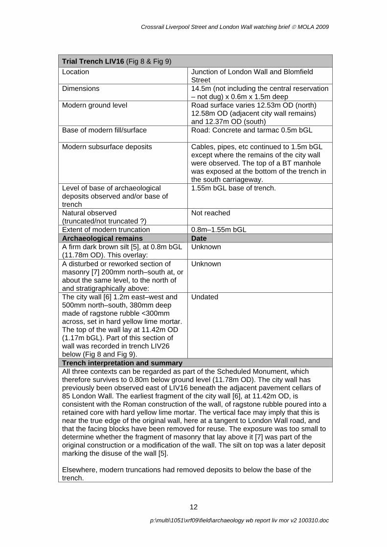
Crossrail Liverpool Street and London Wall watching brief © MOLA 2009
Trial Trench LIV16 (Fig 8 & Fig 9) Location Junction of London Wall and Blomfield
Street Dimensions 14.5m (not including the central reservation
– not dug) x 0.6m x 1.5m deep Modern ground level Road surface varies 12.53m OD (north)
12.58m OD (adjacent city wall remains) and 12.37m OD (south)
Base of modern fill/surface Road: Concrete and tarmac 0.5m bGL
Modern subsurface deposits Cables, pipes, etc continued to 1.5m bGL except where the remains of the city wall were observed. The top of a BT manhole was exposed at the bottom of the trench in the south carriageway.
Level of base of archaeological deposits observed and/or base of trench
1.55m bGL base of trench.
Natural observed (truncated/not truncated ?)
Not reached
Extent of modern truncation 0.8m–1.55m bGL Archaeological remains Date A firm dark brown silt [5], at 0.8m bGL (11.78m OD). This overlay:
Unknown
A disturbed or reworked section of masonry [7] 200mm north–south at, or about the same level, to the north of and stratigraphically above:
Unknown
The city wall [6] 1.2m east–west and 500mm north–south, 380mm deep made of ragstone rubble <300mm across, set in hard yellow lime mortar. The top of the wall lay at 11.42m OD (1.17m bGL). Part of this section of wall was recorded in trench LIV26 below (Fig 8 and Fig 9).
Undated
Trench interpretation and summary All three contexts can be regarded as part of the Scheduled Monument, which therefore survives to 0.80m below ground level (11.78m OD). The city wall has previously been observed east of LIV16 beneath the adjacent pavement cellars of 85 London Wall. The earliest fragment of the city wall [6], at 11.42m OD, is consistent with the Roman construction of the wall, of ragstone rubble poured into a retained core with hard yellow lime mortar. The vertical face may imply that this is near the true edge of the original wall, here at a tangent to London Wall road, and that the facing blocks have been removed for reuse. The exposure was too small to determine whether the fragment of masonry that lay above it [7] was part of the original construction or a modification of the wall. The silt on top was a later deposit marking the disuse of the wall [5]. Elsewhere, modern truncations had removed deposits to below the base of the trench.
12
p:\multi\1051\xrf09\field\archaeology wb report liv mor v2 100310.doc

Crossrail Liverpool Street and London Wall watching brief © MOLA 2009
Trial Trench LIV19 (Fig 11) Location Old Broad Street junction with London Wall Dimensions 14.2 (including east and east pavements) x
0.6m x 1.5m deep Modern ground level Road surface varies 13.14m OD (west)
13.21m OD (centre) and 13.10m OD (east) Base of modern fill/surface Road: Tarmac 0.1m bGL
Decayed concrete bed merges with crushed concrete filling service trenches. Pavement: slabs 70mm thick over <200mm of concrete bed.
Modern subsurface deposits Cables, pipes etc occupy the full 1.5m deep trench, except for the remains of a late 18th or 19th-century cellar. The top of a BT manhole was exposed at the bottom of the trench in the south carriageway.
Level of base of archaeological deposits observed and/or base of trench
1.5m bGL base of trench.
Natural observed (truncated/not truncated ?)
Not reached
Extent of modern truncation 1.2m–1.5m bGL Archaeological remains Date Two red-brick cellar walls [3], 1.2m bGL (c 12.0m OD, see Fig 11).
Late 18th- or 19th-century, based on brick styles and late 19th-century pottery in disturbed fills
Trench interpretation and summary A great many services occupied the width of this trench. The walls of a late 18th- or 19th-century cellar were observed between gaps in the services. There were no observations of the city wall, but there were also many areas where the full depth of the trench (1.5m) could not be reached because of the multiple services. Therefore the city wall might survive beneath the services, although it may be truncated if later cellars are also present.
13
p:\multi\1051\xrf09\field\archaeology wb report liv mor v2 100310.doc
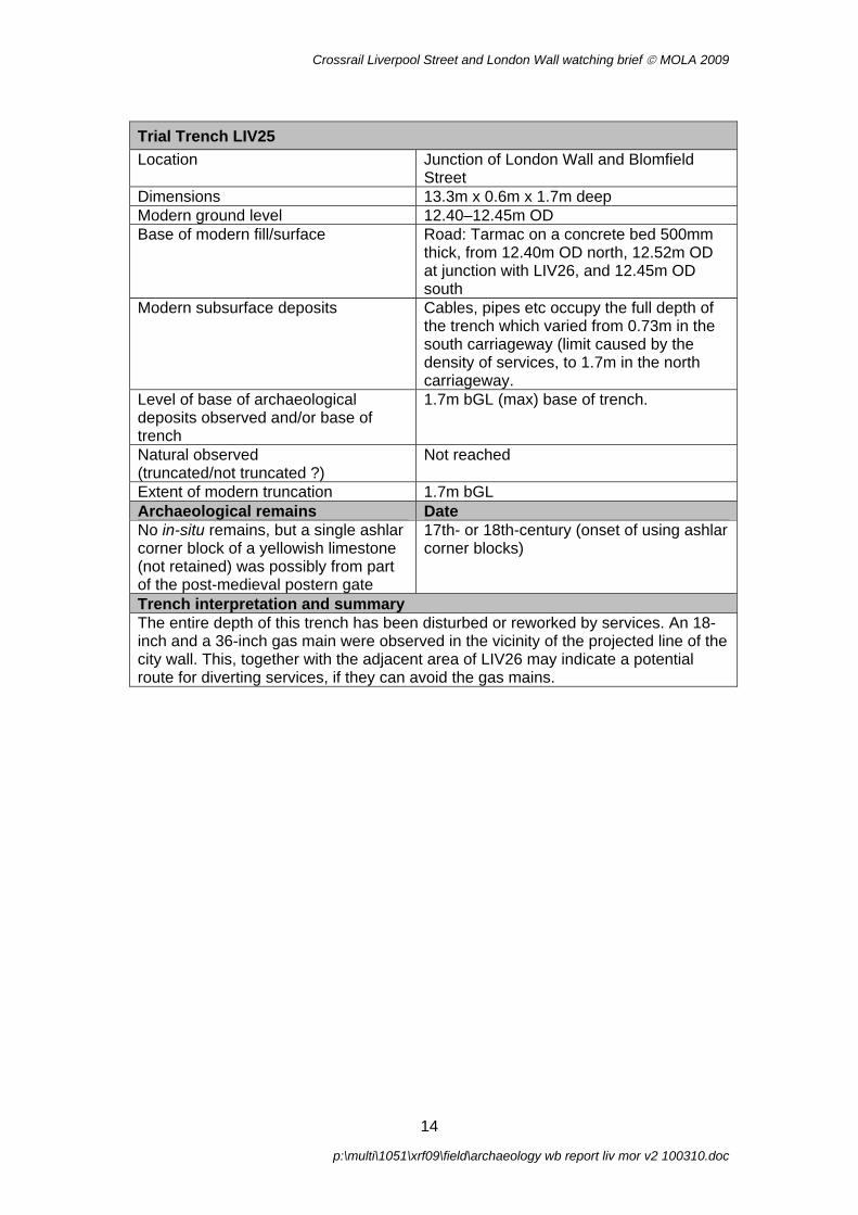
Crossrail Liverpool Street and London Wall watching brief © MOLA 2009
Trial Trench LIV25 Location Junction of London Wall and Blomfield
Street Dimensions 13.3m x 0.6m x 1.7m deep Modern ground level 12.40–12.45m OD Base of modern fill/surface Road: Tarmac on a concrete bed 500mm
thick, from 12.40m OD north, 12.52m OD at junction with LIV26, and 12.45m OD south
Modern subsurface deposits Cables, pipes etc occupy the full depth of the trench which varied from 0.73m in the south carriageway (limit caused by the density of services, to 1.7m in the north carriageway.
Level of base of archaeological deposits observed and/or base of trench
1.7m bGL (max) base of trench.
Natural observed (truncated/not truncated ?)
Not reached
Extent of modern truncation 1.7m bGL Archaeological remains Date No in-situ remains, but a single ashlar corner block of a yellowish limestone (not retained) was possibly from part of the post-medieval postern gate
17th- or 18th-century (onset of using ashlar corner blocks)
Trench interpretation and summary The entire depth of this trench has been disturbed or reworked by services. An 18-inch and a 36-inch gas main were observed in the vicinity of the projected line of the city wall. This, together with the adjacent area of LIV26 may indicate a potential route for diverting services, if they can avoid the gas mains.
14
p:\multi\1051\xrf09\field\archaeology wb report liv mor v2 100310.doc

Crossrail Liverpool Street and London Wall watching brief © MOLA 2009
Trial Trench LIV26 (Fig 8 & Fig 10) Location Junction of London Wall and Blomfield
Street Dimensions 16.0m x 0.6m x 1.8m deep Modern ground level c 12.40–12.58m OD Base of modern fill/surface Tarmac and concrete 300–500mm thick
(from 12.52m–12.58m OD west to east) Modern subsurface deposits Cables, pipes etc to base of trench in parts Level of base of archaeological deposits observed and/or base of trench
1.8m bGL base of trench.
Natural observed (truncated/not truncated ?)
Not reached
Extent of modern truncation 1.2m–1.8m bGL Archaeological remains Date The city wall [6]. Part of this section of wall was recorded in trench LIV16 (above). See LIV16 for the description, and Fig 8 and Fig 10.
Undated
Trench interpretation and summary This trench was designed to follow the line of the city wall exposed in LIV16. It uncovered the masonry remains to the point at which it had been truncated by a modern water main. West of the water main was a manhole, and west of that the width of the trench was reduced to fit between services. Collapsing sides required excavating the trench deeper than the intended depth, to 1.8m bGL. No evidence of the city wall or the later postern gate were found in this western area of the trench, but modern batteries in backfill indicated the location of headings dug below the level of ducts. It is possible that remains survive at a lower depth than this.
15
p:\multi\1051\xrf09\field\archaeology wb report liv mor v2 100310.doc

Crossrail Liverpool Street and London Wall watching brief © MOLA 2009
3.2.2 Trial trenches in Liverpool Street
Trench LIV5 Location Liverpool Street Dimensions 27.5m x 0.6m x 1.3m deep maximum Modern subsurface deposits Modern backfill, concrete and service
pipes and cables varying between 0.17m and 1.3m bGL
Level of base of archaeological deposits observed and/or base of trench
Base of trench: 1.3m bGL (max)
Natural observed (truncated/not truncated ?)
N/A
Extent of modern truncation Modern backfill, concrete and service pipes and cables along majority of length of trench.
Archaeological remains Date Mixed dumps, consisting of a mid grey/brown silty clay, with animal bone, CBM fragments, oyster shell, CTP and occasional disarticulated human bone [1]
Post-medieval
Trench interpretation and summary Modern backfill, concrete and service pipes and cables along majority of length of trench. Small area of undisturbed mixed dumps with occasional disarticulated human bone was observed at 1.3m bGL, but not excavated. Ex situ Human bone was bagged and reburied within the trench.
Trench LIV6 Location Liverpool Street Dimensions 27.0m x 0.6m x 1.5m deep maximum Modern subsurface deposits Modern backfill, concrete and service
pipes and cables varying between 0.25m and 1.5m bGL
Level of base of archaeological deposits observed and/or base of trench
Base of trench: 1.5m bGL (max)
Natural observed (truncated/not truncated ?)
N/A
Extent of modern truncation Modern backfill, concrete and service pipes and cables along full length of trench.
Archaeological remains Date None
Trench interpretation and summary Modern backfill, concrete and service pipes and cables occupied the whole area of the trench. A small quantity of disarticulated human bone found throughout this modern disturbance, and was bagged and reburied within the trench.
16
p:\multi\1051\xrf09\field\archaeology wb report liv mor v2 100310.doc

Crossrail Liverpool Street and London Wall watching brief © MOLA 2009
Trench LIV8 Location Junction of Liverpool Street and Old
Broad Street Dimensions 9.85m x 0.4m x 1.2m deep max Modern subsurface deposits Modern backfill, concrete and service
pipes and cables varying between 0.17m and 1.2m bGL
Level of base of archaeological deposits observed and/or base of trench
Base of trench: 1.2m bGL (max)
Natural observed (truncated/not truncated ?)
N/A
Extent of modern truncation Modern backfill, concrete and service pipes and cables along full length of trench.
Archaeological remains Date None
Trench interpretation and summary Modern backfill, concrete and service pipes and cables along full length of trench.
Trench LIV29 Location Liverpool Street Dimensions 6.5m x 0.55m x 1.4m deep max Modern subsurface deposits Modern backfill, concrete and service
pipes and cables varying between 0.15m and 1.4m bGL
Level of base of archaeological deposits observed and/or base of trench
Base of trench: 1.4m bGL (max)
Natural observed (truncated/not truncated ?)
N/A
Extent of modern truncation Modern backfill, concrete and service pipes and cables along full length of trench.
Archaeological remains Date None
Trench interpretation and summary Modern backfill, concrete and service pipes and cables along full length of trench.
17
p:\multi\1051\xrf09\field\archaeology wb report liv mor v2 100310.doc

Crossrail Liverpool Street and London Wall watching brief © MOLA 2009
3.3 Summary of results
3.3.1 City wall The city wall was recorded in two areas. To the west it was recorded in trench MOR18, context [2] (Fig 4). The exposure was up to 0.75m wide in the trench, and the wall continued for an unknown distance to the west and east of it (Fig 5 & Fig 6). Whilst the external faces were obscured by cables and a gas main (Fig 7), the width of the wall exposed (2.75m) is comparable to reliable observations elsewhere. The wall core was made of ragstone rubble up to 190mm across, set in yellow sandy lime mortar. The highest surviving stone was at 12.03m OD, 0.51m bGL. A small amount of sandy gravelly brickearth abutted and overlay the wall on the north side [4]. It was left in place. The edges of the wall were obscured by live services, therefore the external faces probably lay near to the point where the wall was obscured. This section of masonry lies on the line of the city wall predicted in the DDBA (Crossrail 2008a, see Annex 1), but the width is marginally wider than that predicted (Fig 12, red dashed line). The results of the watching brief allow the reconstructed line of the city wall to be slightly revised in the area between Moorgate and Circus Place (Fig 12, blue dashed line), if an allowance is made for the facings which did not survive in trench MOR18. The southern edge of the wall foundations were observed at site AOP99 and the revised reconstruction uses that as the south line of surviving masonry. The northern face of the wall at the nearest modern observations on which to base a projection (site AOP99), had been refaced at some period – removing the ferruginous sandstone decorative plinth seen elsewhere. It is possible that the thickness of the wall was reduced when this occurred. However, slightly further to the east, the original wall face survived at LON82, and this has been used as a reference point for the northern edge. A further part of city wall [6] was exposed in trenches LIV16 and LIV26 (Fig 8–Fig 10). It was 1.3m long east–west (truncated on the west side and continued for an unknown distance beyond the trench edge to the east) and 0.5m north–south. Part of the south edge had a vertical face, and may reflect where the facing blocks had been removed. It falls within the 2008 reconstruction of the line of the city wall, which therefore does not need revision in this area. The western end of city wall [6] appears to be the southern end of the section recorded by Compass Archaeology in a watching brief for Thames Water in 2008, see Fig 8 (site WBH06, Geoff Potter, pers comm & Crossrail 2009a). The location of the latter was plotted from features shown on OS mapping, and does not match the directly-surveyed section [6]. It is most likely that the WBH06 section is relatively accurately located north–south (ie in relation to the width of the city wall), but that on the east–west axis (ie along the wall), it should be relocated c 0.4m to the west, to make the western edges of the sections match. It should be noted that whilst wall section [6] was truncated to the west, the WBH06 section was only truncated in its southern part; to the north it appears to have extended west and east of the Thames Water trench. The top of the wall [6] was at 11.47m OD. However, additional masonry [7] (Fig 9) over the top of this wall (which can also be considered part of the Scheduled Monument) survived to 11.78m OD (0.8m bGL – the same depth recorded for the Compass Archaeology finding, WBH06). This area of masonry was observed in an
18
p:\multi\1051\xrf09\field\archaeology wb report liv mor v2 100310.doc

Crossrail Liverpool Street and London Wall watching brief © MOLA 2009
exposure 600mm east–west, 200mm north–south and 200mm high, and is of the same materials as the city wall elsewhere, yellow sandy hard lime mortar and ragstone rubble. This masonry fragment [7] may be a separate part of the original construction from that recorded below it [6], or it could be a later remodelling of the city wall. The northern edge does not align with the earlier phase of the city wall, and this later masonry may be truncated in that area. Over both areas of masonry [6] and [7], there was firm dark grey-brown ashy silt [5]. It filled cavities in the masonry up to 400mm deep (left in situ). A potential route for new services was identified at the junction of the west side of Blomfield Street and London Wall. It includes the western carriageway and the central reservation. The area of LIV26 south of these points did not expose remains of the city wall (it is possible that remains survive at a greater depth, below 10.75m OD, 1.8m bGL).
3.3.2 Human remains Of the trenches in Liverpool Street, only trench LIV5 produced any potential archaeological deposits within the depth of excavation (1.2–1.5m). Here mixed dumps with occasional disarticulated human bone were observed at 1.3m bGL, but not excavated [1]. This may be the disturbed upper levels of deep cemetery deposits, similar to those seen in earlier fieldwork in this area, eg as exposed within a shaft in Liverpool Street where the densely-packed burials extended down to 3.2m bGL (Crossrail 2009a, 3.2). Disarticulated human bone was also observed within modern backfill in trench LIV6.
3.3.3 Other remains At the junction of Old Broad Street with London Wall, the only archaeological remains exposed were a red-brick cellar [3] in LIV19 (Fig 11). Remains of buildings demolished in the 1950s were recorded in the north carriageway of London Wall, west of Moorgate (trench MOR19). Such cellars may have abutted and/or cut into the Roman and medieval city wall, although the latter was not exposed within the trenches. The line of Blomfield Street is that of one channel of the former Walbrook stream. A BT manhole exposed at the base of LIV16 south of the central reservation (beneath which it extended) was observed in the 1980s, and had stream sediments from approximately 2m to 4m bGL (LWB89).
19
p:\multi\1051\xrf09\field\archaeology wb report liv mor v2 100310.doc
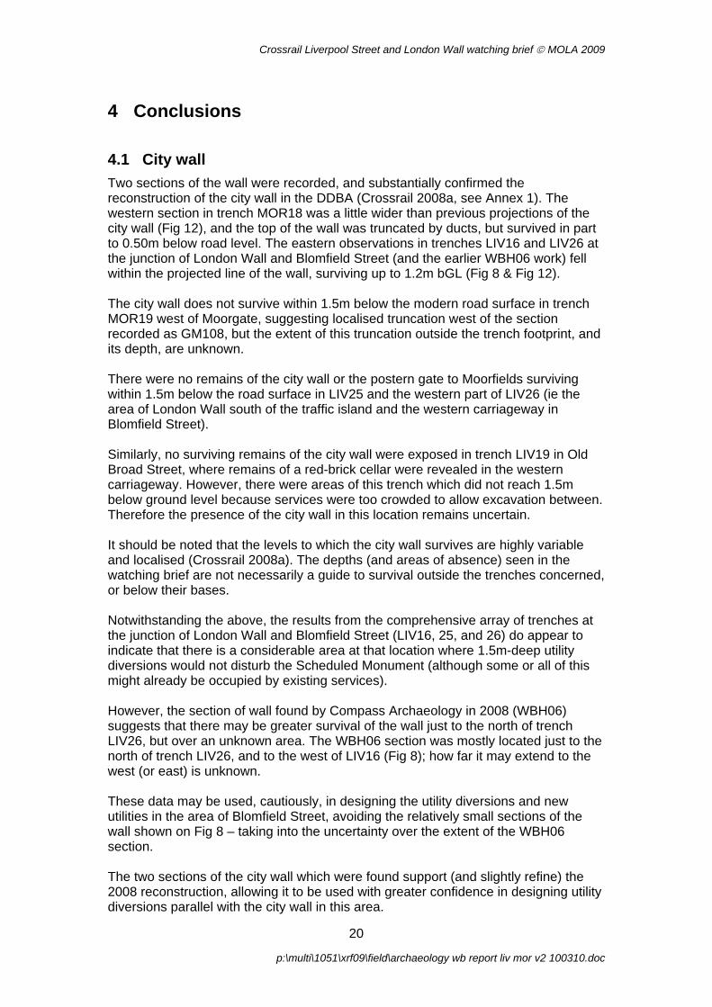
Crossrail Liverpool Street and London Wall watching brief © MOLA 2009
4 Conclusions
4.1 City wall Two sections of the wall were recorded, and substantially confirmed the reconstruction of the city wall in the DDBA (Crossrail 2008a, see Annex 1). The western section in trench MOR18 was a little wider than previous projections of the city wall (Fig 12), and the top of the wall was truncated by ducts, but survived in part to 0.50m below road level. The eastern observations in trenches LIV16 and LIV26 at the junction of London Wall and Blomfield Street (and the earlier WBH06 work) fell within the projected line of the wall, surviving up to 1.2m bGL (Fig 8 & Fig 12). The city wall does not survive within 1.5m below the modern road surface in trench MOR19 west of Moorgate, suggesting localised truncation west of the section recorded as GM108, but the extent of this truncation outside the trench footprint, and its depth, are unknown. There were no remains of the city wall or the postern gate to Moorfields surviving within 1.5m below the road surface in LIV25 and the western part of LIV26 (ie the area of London Wall south of the traffic island and the western carriageway in Blomfield Street). Similarly, no surviving remains of the city wall were exposed in trench LIV19 in Old Broad Street, where remains of a red-brick cellar were revealed in the western carriageway. However, there were areas of this trench which did not reach 1.5m below ground level because services were too crowded to allow excavation between. Therefore the presence of the city wall in this location remains uncertain. It should be noted that the levels to which the city wall survives are highly variable and localised (Crossrail 2008a). The depths (and areas of absence) seen in the watching brief are not necessarily a guide to survival outside the trenches concerned, or below their bases. Notwithstanding the above, the results from the comprehensive array of trenches at the junction of London Wall and Blomfield Street (LIV16, 25, and 26) do appear to indicate that there is a considerable area at that location where 1.5m-deep utility diversions would not disturb the Scheduled Monument (although some or all of this might already be occupied by existing services). However, the section of wall found by Compass Archaeology in 2008 (WBH06) suggests that there may be greater survival of the wall just to the north of trench LIV26, but over an unknown area. The WBH06 section was mostly located just to the north of trench LIV26, and to the west of LIV16 (Fig 8); how far it may extend to the west (or east) is unknown. These data may be used, cautiously, in designing the utility diversions and new utilities in the area of Blomfield Street, avoiding the relatively small sections of the wall shown on Fig 8 – taking into the uncertainty over the extent of the WBH06 section. The two sections of the city wall which were found support (and slightly refine) the 2008 reconstruction, allowing it to be used with greater confidence in designing utility diversions parallel with the city wall in this area.
20
p:\multi\1051\xrf09\field\archaeology wb report liv mor v2 100310.doc
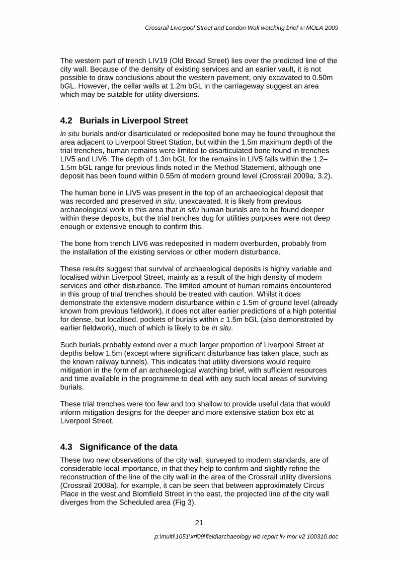
Crossrail Liverpool Street and London Wall watching brief © MOLA 2009
The western part of trench LIV19 (Old Broad Street) lies over the predicted line of the city wall. Because of the density of existing services and an earlier vault, it is not possible to draw conclusions about the western pavement, only excavated to 0.50m bGL. However, the cellar walls at 1.2m bGL in the carriageway suggest an area which may be suitable for utility diversions.
4.2 Burials in Liverpool Street in situ burials and/or disarticulated or redeposited bone may be found throughout the area adjacent to Liverpool Street Station, but within the 1.5m maximum depth of the trial trenches, human remains were limited to disarticulated bone found in trenches LIV5 and LIV6. The depth of 1.3m bGL for the remains in LIV5 falls within the 1.2–1.5m bGL range for previous finds noted in the Method Statement, although one deposit has been found within 0.55m of modern ground level (Crossrail 2009a, 3.2). The human bone in LIV5 was present in the top of an archaeological deposit that was recorded and preserved in situ, unexcavated. It is likely from previous archaeological work in this area that in situ human burials are to be found deeper within these deposits, but the trial trenches dug for utilities purposes were not deep enough or extensive enough to confirm this. The bone from trench LIV6 was redeposited in modern overburden, probably from the installation of the existing services or other modern disturbance. These results suggest that survival of archaeological deposits is highly variable and localised within Liverpool Street, mainly as a result of the high density of modern services and other disturbance. The limited amount of human remains encountered in this group of trial trenches should be treated with caution. Whilst it does demonstrate the extensive modern disturbance within c 1.5m of ground level (already known from previous fieldwork), it does not alter earlier predictions of a high potential for dense, but localised, pockets of burials within c 1.5m bGL (also demonstrated by earlier fieldwork), much of which is likely to be in situ. Such burials probably extend over a much larger proportion of Liverpool Street at depths below 1.5m (except where significant disturbance has taken place, such as the known railway tunnels). This indicates that utility diversions would require mitigation in the form of an archaeological watching brief, with sufficient resources and time available in the programme to deal with any such local areas of surviving burials. These trial trenches were too few and too shallow to provide useful data that would inform mitigation designs for the deeper and more extensive station box etc at Liverpool Street.
4.3 Significance of the data These two new observations of the city wall, surveyed to modern standards, are of considerable local importance, in that they help to confirm and slightly refine the reconstruction of the line of the city wall in the area of the Crossrail utility diversions (Crossrail 2008a). for example, it can be seen that between approximately Circus Place in the west and Blomfield Street in the east, the projected line of the city wall diverges from the Scheduled area (Fig 3).
21
p:\multi\1051\xrf09\field\archaeology wb report liv mor v2 100310.doc

Crossrail Liverpool Street and London Wall watching brief © MOLA 2009
These data will contribute to the design for Crossrail utility diversions, and towards protection of the Scheduled Monument. The results from Liverpool Street regarding human remains provide some data that will contribute towards utility diversions in that area, but broadly confirm previous observations. In both cases the depth limitations of the utilities trial trenches, and the density of existing services, limits any wider inferences with regard to predictive modelling of archaeological deposit survival in relation to proposed Crossrail works (other than utilities).
22
p:\multi\1051\xrf09\field\archaeology wb report liv mor v2 100310.doc

Crossrail Liverpool Street and London Wall watching brief © MOLA 2009
4.4 Publication and archiving The observations of the city wall, a Scheduled Monument, and the refining of the DDBA reconstruction of the route of the wall (which differs significantly from English Heritage’s schedule mapping) are significant results of these two pieces of work. They will be included in the post-excavation assessment for the archaeological works to be conducted for Crossrail’s Liverpool Street Station, and published in an appropriate form. The site archive containing original records (no finds were removed) will be stored in accordance with the terms of the Method Statement (Crossrail 2009a).
5 References Church of England/English Heritage, 2005 Guidance for best practice for treatment of human remains excavated from Christian burial grounds in England
Corporation of London Department of Planning and Transportation, 2004 Planning Advice Note 3: Archaeology in the City of London, Archaeology Guidance
Crossrail, 2005a Environmental Statement
Crossrail, 2005b Assessment of Archaeology Impacts, Technical Report. Part 2 of 6, Central Section, Westbourne Park to Stratford and Isle of Dogs. Crossrail Doc No. 1E0318-C1E00-00001
Crossrail, 2008a, Utilities Diversions: London Wall, Moorgate, Blomfield Street, Old Broad Street, Bishopsgate, Past Observations of City Wall (DDBA for city wall only)
Crossrail, 2008b Environmental Minimum Requirements, (EMR). Crossrail Doc No. CR/HB/EMR/0001
Crossrail, 2008c Crossrail: Works affecting scheduled monuments in the City of London (Scheduled Monument Deed)
Crossrail, 2009a Method Statement for Trial Trenches in Liverpool Street & Moorgate, Document No. CR/DV/LIV/X/MS/00001, version 1.0 (MS)
Crossrail, 2009b Liverpool Street Station, Site-Specific Archaeological Written Scheme of Investigation, v. 1.0, Document No. CR-PN-LIV-EN-SP-00001.
Crossrail, 2009c Archaeology Generic Written Scheme of Investigation, v. 2.0, Document Number 14022008-44ES-P2Z1
Department of the Environment, 1990 Planning Policy Guidance 16, Archaeology and Planning [PPG16]
Institute for Archaeologists (IFA), 2001a By-Laws, Standards and Policy Statements of the Institute for Archaeologists: Standards and guidance – Field Evaluation
Institute for Archaeologists (IFA), 2001b By-Laws, Standards and Policy Statements of the Institute for Archaeologists: Standards and guidance – Watching Brief
Institute for Archaeologists (IFA), supplement 2001 By-Laws, Standards and Policy Statements of the Institute for Archaeologists: Standards and guidance − the collection, documentation conservation and research of archaeological materials
Institute for Archaeologists (IFA; Brickley, M and McKinley, J eds), 2004 Guidelines to the Standards for Recording Human Remains, Institute of Field Archaeologists/British Association of Biological Anthropology and Osteoarchaeology
23
p:\multi\1051\xrf09\field\archaeology wb report liv mor v2 100310.doc

Crossrail Liverpool Street and London Wall watching brief © MOLA 2009
Museum of London, 1994 Archaeological Site Manual 3rd edition
Museum of London, 1998 General Standards for the preparation of archaeological archives deposited with the Museum of London
Museum of London, 2002 A research framework for London archaeology 2002
MOL Archaeology, April 2009 Liverpool Street & Moorgate, Utilities Trial Trenches, Archaeological Watching Brief & Evaluation Method Statement, V. 1.1 (MS)
MOL Archaeology, 2009 Guidelines and notes for Senior Archaeologists on the excavation of human remains and burial grounds. Unpub MOLA guidelines
United Kingdom Institute for Conservation, 1983 Conservation Guidelines No. 2, Packaging and Storage of Freshly-Excavated Artefacts from Archaeological Sites
JB Riney & Co Ltd, March 2009 Environmental Management Plan, Liverpool Street and Moorgate Station Area, Utility Trial Trenching Works, Rev. 0.2
24
p:\multi\1051\xrf09\field\archaeology wb report liv mor v2 100310.doc

Crossrail Liverpool Street and London Wall watching brief © MOLA 2009
6 NMR OASIS archaeological report form
OASIS ID: molas1-66202 Project details Project name Crossrail Utilities trial trenches, near Liverpool Street and Moorgate Stations
Short description of
the project
1.5m-deep Trial trenches to investigate the locations of utilities were monitored. Two
fragments of the city wall were exposed along the line of London Wall road and two
trenches exposed disarticulated human bone near to Liverpool Street Staion. The
results will be used to inform the design of utilities diversions in the area.
Project dates Start: 09-05-2009 End: 01-08-2009
Previous/future
work
No / Yes
Any associated
project reference
codes
XRF09 - Sitecode
Type of project Recording project
Site status Scheduled Monument (SM)
Current Land use Transport and Utilities 1 - Highways and road transport
Monument type CITY WALL Roman
Monument type BURIAL GROUND Post Medieval
Investigation type 'Watching Brief'
Prompt Scheduled Monument Consent
Prompt The Ancient Monuments and Archaeological Areas Act 1979, replaced with a
Scheduled Monument Deed: Crossrail: Works affecting scheduled monuments in the
City of London (Crossrail 2008c) Project location
Country England
Site location GREATER LONDON CITY OF LONDON CITY OF LONDON Crossrail Utilities trial
trenches, near Liverpool Street and Moorgate Stations
Postcode EC2
Study area 11709.48 Square metres
Site coordinates TQ 3289 8153 51.5165425440 -0.08455126364940 51 30 59 N 000 05 04 W Point
Site coordinates TQ 33012 81635 51.5174574470 -0.08275420440790 51 31 02 N 000 04 57 W Line
Site coordinates TQ 33012 81635 51.5174574470 -0.08275420440790 51 31 02 N 000 04 57 W Line
Site coordinates TQ 33116 81604 51.5171542843 -0.08126775386160 51 31 01 N 000 04 52 W Line
Site coordinates TQ 33080 81465 51.5159135338 -0.08183883842330 51 30 57 N 000 04 54 W Line
Site coordinates TQ 32661 81564 51.5169020613 -0.08783724478460 51 31 00 N 000 05 16 W Line
Site coordinates TQ 32938 81490 51.5161717278 -0.08387490719350 51 30 58 N 000 05 01 W Line Project creators
Name of
Organisation
MoL Archaeology
Project brief
originator
Crossrail and HMI-AM
Project design
originator
MoL Archaeology
25
p:\multi\1051\xrf09\field\archaeology wb report liv mor v2 100310.doc
Crossrail Liverpool Street and London Wall watching brief © MOLA 2009
OASIS ID: molas1-66202 (cont’d)
Project
director/manager
George Dennis
Project supervisor David Sankey
Project supervisor Adrian Miles
Type of
sponsor/funding
body
Local authority controlled infrastructure development company
Name of
sponsor/funding
body
Crossrail
Project archives
Physical Archive
Exists?
No
Digital Archive
recipient
LAARC
Digital Media
available
'Images raster / digital photography','Survey','Text'
Paper Archive
recipient
LAARC
Paper Contents 'Stratigraphic'
Paper Media
available
'Context sheet','Manuscript','Notebook - Excavation',' Research',' General
Notes','Photograph','Plan','Section','Unpublished Text'
Paper Archive
notes
trench record sheets
Project bibliography 1
Publication type Grey literature (unpublished document/manuscript)
Title ARCHAEOLOGICAL MONITORING OF GROUND INVESTIGATIONS, utilities trial
trenches, near Liverpool Street and Moorgate Stations
Author(s)/Editor(s) Sankey, D. Miles, A.
Date 2009
Issuer or publisher Museum of London
Place of issue or
publication
London
Description A4 report
Entered by David Sankey (DSankey@museumof london.org.uk)
Entered on 23 October 2009
26
p:\multi\1051\xrf09\field\archaeology wb report liv mor v2 100310.doc

Crossrail Liverpool Street and London Wall watching brief © MOLA 2009
Figures
27
p:\multi\1051\xrf09\field\archaeology wb report liv mor v2 100310.doc

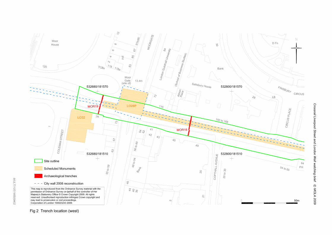


Crossrail Liverpool Street and London Wall watching brief © MOLA 2009
\\data-mwh-2k3\projects\multi\1051\xrf09\field\wb liv mor figs 7 9 & 10.doc
Nor
th w
all f
ace
obsc
ured
by
duct
s
Sou
th w
all f
ace
obsc
ured
by
gas
mai
n
Fig
7 M
OR
18, l
ooki
ng e
ast.
Sca
le is
500
mm
(hal
f-met
re)
Sec
tion
illus
trate
d in
Fig
5
Sec
tion
illus
trate
d in
Fig
6
Wid
th o
f city
wal
l rem
ains
[2]

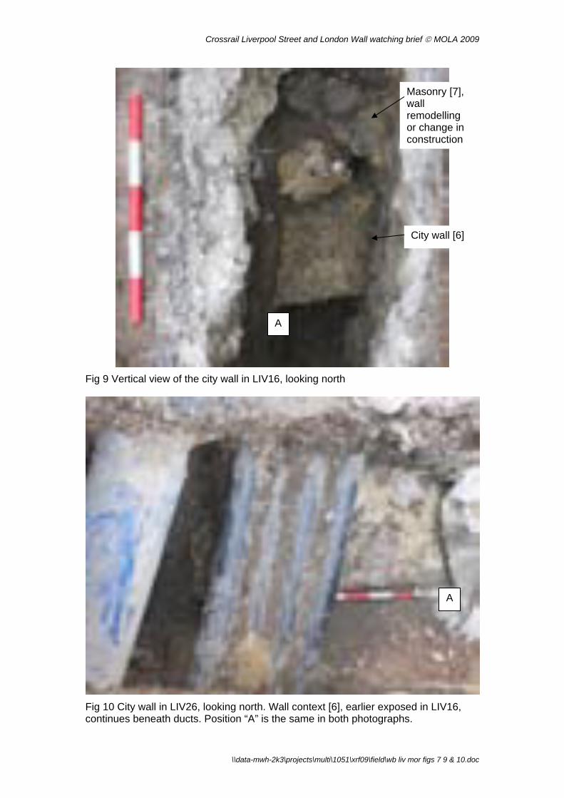
Crossrail Liverpool Street and London Wall watching brief © MOLA 2009
A
City wall [6]
Masonry [7], wall remodelling or change in construction
Fig 9 Vertical view of the city wall in LIV16, looking north
A
Fig 10 City wall in LIV26, looking north. Wall context [6], earlier exposed in LIV16, continues beneath ducts. Position “A” is the same in both photographs.
\\data-mwh-2k3\projects\multi\1051\xrf09\field\wb liv mor figs 7 9 & 10.doc


Crossrail Liverpool Street and London Wall watching brief © MOLA 2009
Annex 1: Additional figures from city wall DDBA (Crossrail 2008a)
p:\multi\1051\xrf09\field\archaeology wb report liv mor v2 100310.doc

GM253GM108
W26
LO26J_26323
anomaly_No2
GM334
AOP99LON82
MOO80
LWL87
LO26P
LO32
26323
Salisbury House
LONDON WALL
MO
OR
GA
TE
Telephone Exchange
CIRCUS
Britannic House
FINSBURY
Station
Bank
Gate
House
Moorgate
Moor
Chambers
Tower
14.0m
12.5m
13.5m
13.4m
12.8m
Guildhall
Bandstand
(School of B
usi
ness S
tudie
s)
Girdlers' Hall
Coleman Street Bldgs
Moorfields Highwalk
Place
Underground Railway
Andre
wes
London G
uild
hall
Univ
ers
ity
Chartered Accountants
PH
Institute of
BM 13.25m
CIR
CU
S P
LA
CE
AVENUE
FO
RE
ST
RE
ET
MO
OR
FIE
LD
S
CO
LE
MA
N S
TR
EE
T
City
Yard
11
115
118
Andrewes Highwalk
Bass
ishaw
Hig
hw
alk
118a
Transport)
7 to 11
Ward Bdy
Justice
St Alphage Highwalk
(London
5
4
2 3
Posts
Alb
ion
3 to 6
16
87
85
36
80
45
12
55
30 to 3
4
8
10
43
56 to 6
0
48 to 5
4
101 to 1
09
49
55 to 5
9
150 to 168
94
54 to 65
14 to 2
4
9
25
84
20 t
o 3
0
91to
95
21
20
40
31
65
137
67
35
74
64
72
46
30
28
51
53
120
34
73
63
1
41
42
7
83
44
141
81
17
19
6
Keats Place
Sub
LB
BASINGHALL AVENUE
13.1m
TCBs
BPs
FB
D Fn
Nun Court
St. Alpage
SD
MOOR PLACE
Great Swan Alley
CO
PT
HA
LL A
VE
NU
E
TCB
LANGTHORN COURT
PC
PH
House
Bank
Bank
TCB
8
40
67
20 t
o 3
0
4
House
TCBBank
42
2
54 to 65
80
6455
3
2FB
Bank
Bank
PH
FORE STREET
Bank
16
Bank
2
Bank
41
Bank
PH
Bank
Bank
2
21
12.5m
16
PH
11
55 to 5
9 25
LB
© MoLAS 2008
0 100m
City wall DDBA: west
Based upon the Ordnance Survey mapping with the permission ofthe Controller of Her Majesty's Stationery Office © Crown Copyright.
Unauthorised reproduction infringes Crown copyright and may lead
to prosecution or civil proceedings. City of London 100023243 2008.
Legend
Scheduled Monuments_230807
CITY WALL RECONSTRUCTION 2008
CITY WALL Observations
RELIABILITY
ACCURATE
GOOD
MODERATE
POOR

BTB89
GM332
WOE94
GLSMR041922
BLM87
GM333
GLSMR041929_02
GLSMR041926
COMPASS_WormwoodSt
CAP86
COMPASS_Blomfield_St
LO26N
LO26A
Priory and Hospital
of
St Mary of Bethlehem
LONDON WALL
CIRCUS
London Wall Buildings
FINSBURY
Bank
Postern
Site of
Broad Street House
(Founded AD 1247)
Capel House
Hope Square
House
Tennis Court
Pinners Hall
14.4m
13.4m
15.5m
12.5m
Wall
Bandstand
BPs
Carpenters' Hall
Hotel
Swedbank
Church
Clerk's Place
BroadBowling Green
PH
New Broad Street
New Broad St
BM 13.82m
The Arcade
Liverpool St Station
CIR
CU
S P
LA
CE
Stree
t
LIVERPOOL STREET
OLD
BR
OA
D S
TR
EE
T
NEW BROAD STREET
BLO
MFIE
LD S
TR
EET
Petty France
BLO
MFIE
LD S
T
WORMWOOD STREET
11
(site of)
Ward Bdy
Bishopsgate ChurchyardBoston
St Botolph without
All Hallows on the Wall
Posts
3
5
23
13
10
1
52 to 5
7
12
84
21
34 to 37
19
25
24
75
17
26
9 to 1
9
87 to 9
1
81 to 9
1
76 to 8
0
80
99
14
20
28
22
1 to 5
27 to 34
105 to 1
08
73
3.5
54 to 65
9
5 to 7
8
6
35
2
29
33
23 to 25
18
15
54 to 62
27
7
46
16
8890
45
42
55
70
53
47
77
85
100
64
86
74
50
82
72
101
31
32
69
63
30
4
Alderman's Walk
St B
oto
lph's
(LRT)
LB
SL
SB
12.8m
AVENUE
TCBs
El Sub Sta
BM 13.10m
Ps
Fn
TH
RO
GM
OR
TO
N A
VE
NU
E
FB
D Fn
22 to
Aust
in F
riars
Passa
ge
BROAD STREET
TCB
GREAT WINCHESTER STREET
Aldermans
BP
White Hart
Bank
19
PH
1418
Bank
33
Pinners Hall
3
Ps
10
20
OLD
BR
OA
D S
TR
EE
T
24
Ps
105 to 1
08
24
1
23
FB
42
75
Bank
7
1
Ward Bdy
21
14
Bank
26
8
10
25
PH
13
PH
26
LONDON WALL
11
15
25
Bank
TCB
Ps
15
20 22
House
LB
11
2
2
64
21
1
SL
Posts
LB
1
19
6
Ba
nk
Ward
Bdy
Bank
12
1916
PH
PH
23
1
25
18
(site of)Posts
17
13
21
2
14.4m
2
LB
© MoLAS 2008
0 100m
City wall DDBA: centre
Based upon the Ordnance Survey mapping with the permission ofthe Controller of Her Majesty's Stationery Office © Crown Copyright.
Unauthorised reproduction infringes Crown copyright and may lead
to prosecution or civil proceedings. City of London 100023243 2008.
Legend
Scheduled Monuments_230807
RECONSTRUCTION_2008
CITY WALL Observations
RELIABILITY
ACCURATE
GOOD
MODERATE
POOR

BTB89
GM349
WOE94
HSD89
GLSMR041929_02
KPH05
COMPASS_WormwoodSt
COMPASS_GoringSt
LO26N
LO26M
LO26L
Staple Hall
Bank
Bethlehem Gate
Broad Street House
Railway
Underground Railway
Underground
House
Tennis Court
Cutlers
Camomile Court
14.8m
13.4m
14.4m
15.8m
15.5m
16.1m
15.7m
BPs
Chatsworth
Stone House
Premier Place
Church
Clerk's Place
Court
CU
TLE
R
PH
HOUNDSDITCH
Exchange
Exchequer
BM 16.37m
BM
16.
14m
The Arcade
Bevis Marks
ST HELEN'S PLACE
STREET
OUTW
ICH S
TR
EET
DEVONSHIRE SQUARE
OLD
BR
OA
D S
TR
EE
T
BIS
HO
PS
GATE
WORMWOOD STREET
11
Air
(site of)
Arc
ade
115
114
119
113112
117
117 to 119
Library
Ward Bdy
Bishopsgate ChurchyardBoston
St Botolph without
1
Posts
7
5
12
50
3
13
35
1 to 9
1 to
6
23
52 to 5
7
84
4
34 to 37
138
66 to
70
1 to 3
37 to 41
81 to 9
1
87 to 9
1
80
99
14
55
31 to 36
121
27 to 3487 to 90
152
17
77 to 84
60 to
68
57 to 60
44
25
952
to 5
8
2
26
16
22
24
144
142
33
140
128 to 1
40
18
12 to 20
120
123
15
154
63
8890
45
38
6
8
19
3a
148
46
10
61
86
60
82
101
20
32
69
78
146
21
64
Alderman's Walk
St B
oto
lph's
LB
Sto
ne H
ous
e C
t
D Fns
15.2m
El Sub Sta
BM 16.23m
Wre
stle
rs C
t
Fn
Pond
Cavendish
FB
22 to
BARBO
N A
LLEY
DEVONSHIRE
Aldermans
CLO
THIE
R S
TREET
White Hart
16
10
1
38
5
Bank
6
16
25
5
1
3
El Sub Sta
9
22
PH
16
Bank
5
Bank
5
26
PH
24
23
Ward
Bdy
PH
2
15LB
6
FB
63
10
17
Ba
nk
Ward Bdy
6
17
35
10
8
Bank
50
33
7
55
PH
1813
4
PH
11
7
12
25
17
15
1
7
9
7
3
33
PH
33
8
© MoLAS 2008
0 100m
City wall DDBA: east
Based upon the Ordnance Survey mapping with the permission ofthe Controller of Her Majesty's Stationery Office © Crown Copyright.
Unauthorised reproduction infringes Crown copyright and may lead
to prosecution or civil proceedings. City of London 100023243 2008.
Legend
Scheduled Monuments_230807
RECONSTRUCTION_2008
CITY WALL Observations
RELIABILITY
ACCURATE
GOOD
MODERATE
POOR

Liverpool Street: Method Statement for Verizon works at Old Broad Street in relation to the Scheduled Monument – City Wall (LO26N)
Document uncontrolled once printed. All controlled documents are saved on the CRL Document System
© Crossrail Limited UNCONTROLLED
Appendix F C503 – Liverpool Street Method Statement, Utilities Diversions – Excavation, Duct Installation, Backfilling.


VINCI Construction UK Limited C503 Liverpool Street
C503-VIN-C-GMS-C101-50010 Rev. 3.0 Page 3 of 55
3
CHECK LIST (tick box as appropriate)
Additional Information Applicable Not Applicable
General Procedure Scope of work Labour force Training Lifting equipment Portable tools Mechanical plant Track mounted vehicles and plant Protection of LUL assets Materials Storage and handling of hazardous substances and materials Temporary structures / False work Working at heights Work permits and licences Temporary lighting and power Control of work with hazardous substances and processes First aid Fire Prevention Excavation Personal Protective Equipment (PPE) Incidents and Reporting of Injuries, Diseases and Dangerous Occurrences (RIDDOR)
Housekeeping Access and egress to authorised personnel Emergency procedures Transportation Signs and notices Systems / Codes of practice Statutory records Noise and vibration Air quality and dust Waste management Protection of water quality Archaeology Nature protection Management of pests and weeds Traffic management Contaminated land Inspection and environmental auditing Records and documentation Live working Manual handling

VINCI Construction UK Limited C503 Liverpool Street
C503-VIN-C-GMS-C101-50010 Rev. 3.0 Page 4 of 55
4
CONTENTS 1. SCOPE OF WORKS ..................................................................................................................................... 5
1.1 Scope of works ........................................................................................................................ 5 1.2 Methodology / Sequence of works .......................................................................................... 5 1.3 Programme ............................................................................................................................ 12 1.4 Access and egress / Signing In Procedure ............................................................................ 12 1.5 Work permits – licenses – other plans required .................................................................... 12 1.6 Temporary Works .................................................................................................................. 13 1.7 Key Operational risks and control measures ......................................................................... 14 1.8 Key Health and Safety risks and control measures ............................................................... 14
2. OPERATIONAL ISSUES ........................................................................................................................... 15 2.1 Effects on operational utilities and road networks and other transport systems ................... 15 2.2 Protection / Disconnection / Alteration of Utilities / LU operational assets ........................... 15
3. LABOUR FORCE AND COMPETENCY .................................................................................................. 16 4. TRAINING .................................................................................................................................................... 16 5. PLANT, EQUIPMENT, MATERIALS AND PORTABLE TOOLS ........................................................... 17
5.1 Plant ....................................................................................................................................... 17 5.2 Fuel handling / Storage .......................................................................................................... 18 5.3 Materials / Storage ................................................................................................................. 18 5.4 Temporary power and lighting ............................................................................................... 18 5.5 Portable tools and equipment ................................................................................................ 19 5.6 Access towers, platforms and scaffolding ............................................................................. 19
6. LIFTING OPERATIONS ............................................................................................................................. 19 7. HEALTH & SAFETY – ROUTINE PRECAUTIONS ........................................................................................ 19
7.1 COSHH .................................................................................................................................. 19 7.2 Asbestos ................................................................................................................................ 20 7.3 Excavations ............................................................................................................................ 20 7.4 Manual Handling .................................................................................................................... 20 7.5 HAVs (Hand arm vibration) .................................................................................................... 21 7.6 Occupational Noise ................................................................................................................ 21 7.7 Welfare facilities ..................................................................................................................... 22 7.8 PPE ........................................................................................................................................ 22 7.9 Safety equipment ................................................................................................................... 22 7.10 Signs & Notices...................................................................................................................... 23 7.11 First aid arrangements ........................................................................................................... 23 7.12 Fire Points .............................................................................................................................. 23 7.13 Inclement weather ................................................................................................................. 23 7.14 Emergency ............................................................................................................................. 24 7.15 Emergency Contacts ............................................................................................................. 26
8. ENVIRONMENTAL PROTECTION .......................................................................................................... 28 8.1 Waste management ............................................................................................................... 28 8.2 Dust management ................................................................................................................. 28 8.3 Noise management ................................................................................................................ 29 8.4 Vibration management ........................................................................................................... 29 8.5 Archaeology ........................................................................................................................... 29 8.6 Groundwater and surface water runoff .................................................................................. 29
Appendix 1 Operational risk assessment Appendix 2 Health and safety risk assessment Appendix 3 Sketches Appendix 4 Lifting operation plan Appendix 5 Temporary works (drawings and sketches only) Appendix 6 Assessments Appendix 7 Briefing sheets Appendix 8 Responsible Person Contact Details

VINCI Construction UK Limited C503 Liverpool Street
C503-VIN-C-GMS-C101-50010 Rev. 3.0 Page 5 of 55
5
1. SCOPE OF WORKS 1.1 Scope of works This method statement covers the civil engineering works required for the diversion of public utilities away from the footprint of the future Liverpool Street Crossrail ticket hall at Liverpool Street C503 project as detailed in section 1.2 of this document. The purpose of this method statement is to outline safe systems of work and methodology to allow the sub-contractor (TBC) to undertake the works. The works are programmed to be undertaken from the start of September 2011 until early January 2012. The works will take place in Eldon Street, Liverpool Street, Sun Street, New Broad Street, Old Broad Street and Blomfield Street. Drawing ref CRL1-XRL-U-DDA-C101-00109 is given in Appendix 3 showing the streets affected by these works. The public utilities diversions require excavations for joint bays, duct routes, cable pits and access chambers in Eldon Street, Liverpool Street, New Broad Street, Old Broad Street and Blomfield Street, and include backfilling and reinstatement of the highway. The archaeology works on Liverpool Street will require initial breaking of the ground for 500mm. If during the course of the works it becomes evident that certain activities fall outside of the scope described in this document, these activities will not be allowed to proceed until an addendum has been agreed to the existing Method Statement or a separate Method Statement and Risk Assessment has been produced to cover a significant change in scope. This method statement does not cover:
the site establishment works for the main worksites in Liverpool Street and 11-12 Blomfield Street which take place before the utilities diversions;
traffic management installation follow on works by the utilities companies construction of manholes installation of water or gas pipes works internal to buildings
1.2 Methodology / Sequence of works Pre-works commencement The VCUK and all Sub-contractor works supervisors must have read and understood this document and be prepared to brief the team and start works as follows: They must ensure all competency checks, briefings, issue of permits and licences, and all
other checks and systems are in place as defined in this RA/MS They must ensure that this RA/MS is signed off by VCUK, Crossrail and LU. However work
may proceed when they are more than 6m away from LU assets once the MS is signed by CRL and VCUK.
They must continually ensure that all operatives have read and understood the parts of this Method Statement applicable to their works, and have had the opportunity to review the entire document before signing to indicate they have been instructed correctly.
They must carry out a STARRT briefing at the beginning of each shift which fully briefs the team on the information required to carry out each element of work safely and efficiently in adherence with the MS. This will include confirming the stage the operations have reached, and what stage they are expected to reach in the shift concerned.

VINCI Construction UK Limited C503 Liverpool Street
C503-VIN-C-GMS-C101-50010 Rev. 3.0 Page 6 of 55
6
In particular the briefing must focus on the key operational and safety risks which are highlighted in sections 1.7 and 1.8
The supervisors must be prepared so that any changes in circumstances can be quickly identified and reported to mitigate any risks undetected to date.
Commencement of works: All works listed below must be carried out in compliance with the conditions stated in this full MS. Example of this include Lifting operations must follow guidance on lifting plans, manual handling must be assessed, PPE must be worn as outlined for each task. To avoid repetition the conditions imposed by these other sections of the MS are not repeated here – but must be referred to before each operation commences. The works described below are programmed to take place in Blomfield Street, Eldon Street, New Broad Street, Old Broad Street, Sun Street and Liverpool Street. The works will be undertaken the sub-contractor (TBC) who will be appointed by VCUK. Works element 1) Site set-up The Traffic Management (TM) will be established by others and a separate approved MS will be in place prior works starting. The first activity will be to install heras fencing panels with support bases within the TM boundaries. No pedestrian access will be allowed into the area whilst this activity is going on. Fencing will be brought to the site using a flatbed or tipper truck and offloaded manually one by one. This will be done by a minimum of 2no operatives. Once installed, fences will be double-clipped for the full length. Support struts will be installed at every other panel to provide stability. No length of fencing will be installed longer than 40m without a temporary works design being in place. For the duration of excavation and breaking out works, acoustic blankets will be attached to the feras panels. The heras panel fence will be visually checked daily by the VCUK Supervisor and weekly by the VCUK Temporary Works Co-ordinator and VCUK Temporary Works Supervisor to ensure stability of the fence. They will be checking for the connections between panels to be tightly fixed in place and the panels to be securely in their bases. Works element 2a) Excavation for non LU-affected areas
1) Permit to penetrate (VCUK) and permit to dig (sub-contractor) need to be in place and checked by the VCUK Supervisor.
2) Prior to the ground being broken the excavation area will be scanned by a trained subcontractor operative with a CAT and signal generator and checked against the Permit to Penetrate. Existing service records will be cross-checked.
3) Services detected will be marked on the surface using line spray within and 2m beyond the footprint of the area to be excavated wherever possible.
4) Based on the utilities agree with the VCUK Supervisor a suitable location for starting excavation. If location for excavation is moved, then start again from step 1.
5) The tarmac will be saw-cut using floor saw and broken out using a 6t excavator with hydraulic breaker attachment. Where this is not possible, a hand-held breaker will be used.

VINCI Construction UK Limited C503 Liverpool Street
C503-VIN-C-GMS-C101-50010 Rev. 3.0 Page 7 of 55
7
6) The 300mm mass concrete sub-base will be broken out by using the excavator. A banksman will be in attendance at all times whilst plant is in operation. Where this is not possible, a hand-held breaker will be used by the operatives.
7) In the case that human remains are found or suspected to exist in the initial excavation, all works will be stopped and the archaeology subcontractor will be called on-site. Works only to recommence after the VCUK Site Supervisor has given authorisation.
8) The works on the archaeological pits will stop at a maximum of 500mm depth. 9) The utilities excavations will continue past this depth of 500mm and be re-scanned by a
trained subcontractor operative with a CAT and signal generator for every 500mm of excavation depth to reconfirm location of services.
10) Made ground will be excavated by hand around the services to form trench. No excavation will be undertaken using mechanical excavator within 500mm of known or suspected services.
11) Waste material will be transferred to the Liverpool Street compound using a dumper where it will be stored before it is tested and removed by the appointed subcontractor.
12) Where an inspection deems the ground unstable, temporary ground support will be installed to an design approved by VCUK. A VCUK Engineer will carry out inspections of all excavations on a daily basis.
13) If services further to the ones known are identified, works will stop and refer back to VCUK supervision and management for guidance.
The main hazards arising from these works and their controls include Hazard: Striking live services Controls:
Service records on site Permit to penetrate and permit to dig in place CAT scan of area prior to and throughout excavation Hand dig within 500mm of known or suspected services Banksman with excavator at all times
Hazard: Incorrect use of mechanical plant and/or unsuitable equipment causing damage to property Control:
Site Briefing and Tool Box Talks will be given to all personnel. Supervision at all times. Plant Certification, Trained Operatives (CPCS) Use of banksmen, traffic marshals, traffic management.
Works element 2b) Excavation for LU-affected areas No mechanical excavation will be undertaken within 6m of known LU assets.
1) The areas where LU assets are located and clearly shown on the LU SED drawing attached in Appendix 3. On the same drawing, ‘restricted areas’ are marked in light red colour that requires LU approval prior to commencing work activities in these areas. Works in and around LU infrastructure will be undertaken as per the LU Infrastructure Protection Plan and LU WPP. Works classed as LUL Interface Trenches will be undertaken as per the Appendix C of the LU Streetworks Assessment Report for Utilities Diversions. The proposed arrangements have been incorporated in the points below.
2) LU assets include the LU tunnels (Metropolitan and Circle lines) on Blomfield Street and Old Broad Street; the QVT; the LU substation and the LU ticket hall in Old Broad Street.
VINCI Construction UK Limited C503 Liverpool Street
C503-VIN-C-GMS-C101-50010 Rev. 3.0 Page 8 of 55
8
Any works which could ‘potentially impact’ LU infrastructure will be agreed/approved by LU before any works commence.
3) Permit to penetrate (VCUK) and permit to dig (sub-contractor) need to be in place and checked by the VCUK Supervisor.
4) Works to trenches which are indicated as ‘LUL Interface’ trenches (i.e. within 3.0m of LU assets) shall only be undertaken with the attendance of the LU inspector. No works shall commence or continue in the absence of the LU Inspector except for carriageway reinstatement, or with the express permission to carry out works from LU.
5) In the event of an emergency the LU Inspector will be the first point of contact on site for VCUK and their Subcontractor and co-ordination between the site works and LU. If the LU Inspector is not available at the time, a competent person i.e. VCUK Supervisor (VCUK Emergency Controller as per C503 Emergency Preparedness Plan) will take control of the event.
6) Prior the ground being broken the excavation area will be scanned by a trained subcontractor operative with a CAT and signal generator and checked against the Permit to Penetrate. Existing service records will be cross-checked.
7) Services detected will be marked on the surface using line spray within and 2m beyond the footprint of the area to be excavated wherever possible.
8) Based on the marked utilities and location of LU assets agree with the VCUK Supervisor a suitable location for starting excavation. If location for excavation is moved, then start again from step 1.
9) The carriageway surface breakout method shall be as per the following conditions: Within and up to 3.0m plan distance of the edge of a LU asset (tunnel), the breakout
method shall be limited to use of hand-held heavy duty road breaker type equipment. From 3.0m to 5.0m plan distance from the edge of a LU asset (tunnel), the breakout
method shall be limited to a 3-ton mini-excavator with breaker attachment. Beyond 5.0m distance from the edge of a LU asset (tunnel), the breakout method
shall be by normal and appropriate means. This includes where assets are greater than 5.0m deep below the bottom of the trench excavations but may be within 5.0m plan distance.
In all instances, the breakout method shall take in to account all other considerations specific to the location.
10) The tarmac will be saw-cut using a floor saw and broken out using a a hand-held breaker.
11) The 300mm mass concrete sub-base will then be broken out using a hand-held pneumatic breaker or otherwise as described above.
12) In the case that human remains are found or suspected to exist in the initial excavation, all works will be stopped and the archaeology subcontractor will be called on-site. Works only to recommence after the VCUK Site Supervisor has given authorisation.
13) The works on the archaeological pits will stop at a maximum of 500mm depth. 14) The utilities excavations will continue past this depth of 500mm and be re-scanned by a
trained subcontractor operative with a CAT and signal generator for every 500mm of excavation depth to reconfirm location of services.
15) Made ground will be excavated by hand around the services to form trench. Where a suspected LU asset is encountered during excavation, operatives will cease work and seek further instruction from VCUK Supervisor.
16) Where unexpected concrete obstructions are located within the trench, these shall not be broken out. Where the excavation works cannot proceed as a result of such obstacles, the works will cease. All such obstacles will be recorded and reported and works are not to proceed until the obstacle function is known and relevant parties agree upon the removal, or an agreed diverted route agreed.

VINCI Construction UK Limited C503 Liverpool Street
C503-VIN-C-GMS-C101-50010 Rev. 3.0 Page 9 of 55
9
17) The excavation depth shall not extend to reveal the waterproofing membrane to a LU tunnel or other structure. Excavation shall cease at approximately 100mm depth above the expected depth of the structure. Excavations, if necessary, shall continue by hand below this depth with agreement of the LU Inspector.
18) If, in the unlikely event the waterproofing membrane is revealed and penetrated or damaged, this will be suitably sealed with a waterproof bitumen sealer before the trench is reinstated.
19) Any such repairs will be completed to the satisfaction of the LU Inspector. 20) Waste material will be transferred to the Liverpool Street compound using a dumper
where it will be stored before it is removed by the appointed subcontractor. 21) Where an inspection deems the ground unstable, temporary ground support will be
installed to an design approved by VCUK. A VCUK Engineer will carry out inspections of all excavations on a daily basis.
22) If services further to the ones known are identified, works will stop and refer back to VCUK supervision and management for guidance.
The main hazards arising from these works and their controls are described in works element 1 above and in full in the Risk Assessment in Appendix 2. However, additional risks for this element include: Hazard: Damage to LU assets Controls:
Service and LU records on site Permit to penetrate and permit to dig in place Marking out of known LU assets in area prior to excavation Hand dig within 6m of known LU assets
Hazard: Exposure to high levels of vibration causing serious injury including Hand Arm Vibration Controls:
Avoid use of hand-held breakers when possible Ensure that hand held tools are vibration dampened, regularly serviced and
maintained. Minimise exposure to individual operatives by rotating the workforce and keeping
an HAVS register
Works element 3) Duct Installation
1) Pipe bedding, ducts and other materials will be delivered to and stored in the Liverpool Street site compound. If the storing area is far from the working site, a dumper will be used to handle the material. Manual handling of the ducts, considered to be long load, will require 2no operatives minimum to carry with a banksman leading the group.
2) Pipe bedding will be laid to a minimum of 100mm in the base of the trench in line with the HAUC specification or Utility specification if different. Material will be installed using an excavator wherever possible, pouring into the trench from the bucket. No operatives will be permitted within 2m of this activity within the trench, controlled by the banksman.
3) The bedding material will be manually spread and levelled by the operatives using a shovel.
4) Ducts will be laid in the trench in required configuration and joined together as necessary using dry joints generally but if chemicals are required to be used, the COSHH sheets will be checked and approved by VCUK prior to works. Ducts will be

VINCI Construction UK Limited C503 Liverpool Street
C503-VIN-C-GMS-C101-50010 Rev. 3.0 Page 10 of 55
10
installed to within 1m of any live manholes. No works will be undertaken on live cables or manholes without prior authorisation from the utility provider. If work is to proceed on these, an additional approved Method Statement and/or Risk Assessment for the works will be in place.
5) Pull-cord will be threaded through each duct to ensure utility companies are able to pull cables through at a later stage.
Hazard: Installation of the bedding material into trench Controls:
Banksman to be in attendance at all times when placing the material and will ensure that no person comes within 2m of the works and that no lifting operations take place over people on site.
Hazard: Manual handling of the bedding material and the ducts Controls:
Avoid manual handling where possible and use mechanical aids (e.g. excavator to lay bedding material)
Conduct specific manual handling assessment for each occasion identifying any additional PPE required
Method Statement briefing, Toolbox talks, Supervision
Works element 4) Reinstatement of highway
1) Trench will be backfilled around ducts with bed and surround material in accordance with HAUC specification or Utility specification if different. This will be done using an excavator bucket to pour in material and moved around and compacted by hand using a shovel.
2) The remainder of the trench will be backfilled with granular fill, compacted in accordance with the specification for highway works, using a hand-held compactor (“wacker plate”).
3) Marker tape will be installed in the backfill about 300mm above the ducts and a text on the tape will identify the type of service below.
4) For carriageways, mass concrete sub-base will be cast as per City of London’s highway reinstatement specification (300mm depth for tarmac carriageway, 150mm for granite sett carriageway). For footways, sub-base will be installed as per the City of London’s highway specification. Concrete will be transported to the site using a concrete truck when the pour will be sufficiently large and if there is space available for the truck on site. Due to space limitations, concrete will need to be mixed on site when small quantities of concrete are required and will be transferred from the main site compound to the remote worksites by using the dumper accompanied by a banksman. Mixing of concrete works will be covered by a separate approved MS which will be in place prior to any mixing of concrete on site.
5) Road surface will be reinstated as per the City of London’s highway reinstatement specification (wearing course 50mm deep or granite setts for carriageways; wearing course 25mm deep or yorkstone paviers for footways). Tarmac will be delivered to the site compound using a tipper truck, then will be moved around the site manually for small quantities and using a JCB Airmaster or similar for large quantities; and hand-held rollers will be used to compact it.
6) Road markings will be reinstated as required to replicate existing. This will be done temporarily by hand using line marking paint. This will be replaced with permanent marking when it is required for a substantial area by a specialised sub-contractor and will be covered by a separate approved MS.

VINCI Construction UK Limited C503 Liverpool Street
C503-VIN-C-GMS-C101-50010 Rev. 3.0 Page 11 of 55
11
Hazard: During mixing and placing of concrete; and placing of tarmac – use of incorrect procedures causing serious injury including concrete burns, burns or blindness Controls:
Only trained and competent operatives to place/work with concrete and tarmac Task specific PPE: gauntlets, overalls, long sleeves, goggles, Wellington boots
for concrete works, specialist boots for tarmac laying works to be used Hazard: Vehicle movements around site Controls:
All unnecessary personnel to be excluded from the area with barriers A person will be stationed to direct unnecessary personnel away from the
operations Safety and traffic management signage will be in place A banksman will be on site all the time
Hazard: Spillage of concrete on the highway during transport of material with dumper Controls:
The dumper will only be partly filled The banksman accompanying the dumper will be aware of the concrete spillage
risk and should inform the site supervisor if there is any spillage in order to have the highway cleaned
Whenever possible, concrete to be delivered directly into satellite site Hazard: Exposure to high levels of vibration causing serious injury including Hand Arm Vibration Controls:
Avoid use of hand-held breakers when possible Ensure that hand held tools are vibration dampened, regularly serviced and
maintained. Minimise exposure to individual operatives by rotating the workforce and keeping
an HAVS register Other Routine Arrangements The worksites will be maintained clean, tidy and in good condition at all times. Materials and waste will be stacked tidily with power leads and cables kept tidy to prevent trips.
During the course of the works site operatives will give full consideration to the Health & Safety of all 3rd parties working on or adjacent to the work location. The work site will be kept in an orderly state to avoid endangering any such person.
Upon completion of the work, at the end of each shift the Site Supervisor shall inspect the worksite to ensure that it is left in a clean and tidy condition, all plant and equipment shall be removed and any waste materials will be either stored or taken off site. A road sweeper will be available if required to clean the site compound and highway.
For any period that works will not be taking place in any of the remote worksites, all plant will be removed and the site boundaries will be secured to prevent unauthorised access. For LU-affected sites, the LU inspector will attend weekly LU liaison meetings and can regularly liaise with the VCUK Supervisor to attend works on-site. The LU inspector will make himself known to the VCUK Supervisor prior to entering the site.

VINCI Construction UK Limited C503 Liverpool Street
C503-VIN-C-GMS-C101-50010 Rev. 3.0 Page 12 of 55
12
Closing Actions
Sign out from site VCUK engineer will take as-built records information prior to backfilling ITP check sheets will be signed by relevant parties at each stage Any anomalies will be reported to relevant authority e.g. CoL or Utilities companies CoL to accept road back into use
1.3 Programme The works are programmed to be undertaken from the start of September 2011 until early January 2012. Hours of working are:
Monday - Friday: 08:00 – 18:00 hours Saturday: 08:00 – 13:00 hours
Some work will take place outside of these hours and they will be subject to confirmation. The first deliveries relating to these works are planned to arrive to site on 31st August 2011. For the initial phases of the works the following outline is supplied: Period Activities September Works in Blomfield Street, Eldon Street and Liverpool Street October Works in Blomfield Street, Eldon Street, New Broad Street and Liverpool
Street November Works in New Broad Street, Old Broad Street, Sun Street and Liverpool Street December Utility connections in Blomfield Street, Eldon Street, New Broad Street, Old
Broad Street, Sun Street and Liverpool Street 1.4 Access and egress / Signing In Procedure All personnel must be signed in and out, appropriate to when they are on site. No-one is to pass into or out of the site boundary without doing this, as it may present an unnecessary search and rescue operation having to take place. Control of access / egress will be effected by the installation of a Crossrail approved electronic access control system. This is supplemented by the use of biometric readers at all access points, and card swipe readers at all egress points to site in conjunction with site issued passes. Passes will be issued to and carried by all persons, according to the purpose of their presence on site. Where access cannot be controlled by the electronic access control system, such as the satellite sites, passes will be shown to an identified authorised person when entering or leaving the site and their details recorded on the signing in / out log. Any changes will be notified by the VCUK Site Supervisor at the start of the shift. 1.5 Work permits – licenses – other plans required The following permits, licenses and other plans will be required as part of works covered under this method statement and will need to have been approved as defined on each VCUK standard
VINCI Construction UK Limited C503 Liverpool Street
C503-VIN-C-GMS-C101-50010 Rev. 3.0 Page 13 of 55
13
permit / license / plan format. An outline of what is required is supplied here, please check with the VCUK Supervisor if in doubt: Non-LU Hot Works Permit Non-LU Permit to
Penetrate Non-LU Permit to Enter Confined Space N/A
Non-LU Permit to Load & Unload N/A Non-LU Drill & Fix
Permits N/A LU Access Permits (LONO)
Non-LU Lifting Plan Non-LU Storage Licenses Non-LU Utility Provider
Permits
Non-LU Traffic Approvals Consents (incl. Section
61) Other N/A
1.6 Temporary Works Element Status Notes for sub-contractors Excavations – ground support
To be designed and installed
A temporary works design will be produced where the excavation and ground conditions require one. The design will be approved by VCUK Temporary Works Coordinator.
Excavations – support of exposed utilities
To be designed and installed
A temporary works design will be produced where utilities are exposed and need to remain in place and uninterrupted. The design will be approved by VCUK Temporary Works Coordinator and Utilities
Remote sites establishment – stability of heras fencing
To be designed and installed
A stability check needs to be undertaken for the heras fence with acoustic blankets attached to it. A temporary works design will be produced if required. The design will be approved by VCUK Temporary Works Coordinator.
The items of temporary works for installation or alteration are further described below and drawings and supporting information will be included in Appendix 5 and copies will be available on-site. Ground support – timber ground retaining structure Utilities support – bulk timber spanning across excavation The temporary works design is currently under development. Excavation works will not proceed past the point where any temporary works are required until an approved temporary works design is in place. All temporary works shall be installed/modified/maintained in line with the VCUK Temporary Works Procedure for the project. In addition to daily checks by the sub-contractor, Temporary works will be recorded on the temporary works register and inspected at a minimum on a weekly basis. Inspections will be undertaken and recorded by the Temporary Works Supervisor or Co-ordinator. Additionally all site supervisors will inspect the work area prior to the start of work near temporary works.
VINCI Construction UK Limited C503 Liverpool Street
C503-VIN-C-GMS-C101-50010 Rev. 3.0 Page 14 of 55
14
1.7 Key Operational risks and control measures Key messages to supervision and workforce as part of method statement briefing, refer to RA for full assessments: Hazard: Damage to LU assets from plant or tools Control: hand dig only within 6m of LU assets LU Supervisor on site to discuss works and mark out location of LU assets MS approved by LU Hazard: Services struck by errant vehicle causing loss of services function, explosion, fire Control: Traffic management measures will be put in place prior to commencement of works Signage will be provided to ensure pedestrians and vehicles are clear on diverted routes. Hazard: Spillage of concrete on highway causing pollution and damage to highway and vehicles Control: The dumper will only be partly filled The banksman accompanying the dumper will be aware of the concrete spillage risk and should inform the site supervisor if there is any spillage in order to have the highway cleaned. 1.8 Key Health and Safety risks and control measures Key messages to supervision and workforce as part of method statement briefing, refer to RA for full assessments: Hazard: Striking live services causing serious injury or fatality Control: Service records on site Permit to penetrate and permit to dig in place CAT scan of area prior to excavation Hand dig around known or suspected services Use of insulated tools Good supervision Visibly mark services on ground Hazard: Exposure to high levels of vibration causing serious injury including Hand Arm Vibration Control: Avoid use of hand-held breakers when possible Ensure that hand held tools are vibration dampened, regularly serviced and maintained. Use shock resistant gloves Minimise exposure to individual operatives by rotating the workforce and keeping an HAVS register Hazard: Flying debris produced during breaking the ground works causing serious injury or blindness Control: Exclusion zones will be put in place to protect operatives from flying debris during breaking operations. Acoustic blankets on heras fence. Operatives taking part in the breaking operations will need to wear impact resistant goggles. Hazard: Accident or incident involving site operatives working alone Control: During the works operatives will not be permitted to work alone. All gangs to ensure no member of the team is left working at end of shift or at break times

VINCI Construction UK Limited C503 Liverpool Street
C503-VIN-C-GMS-C101-50010 Rev. 3.0 Page 15 of 55
15
Hazard: Operatives struck by moving plant causing serious injury or fatality Control: All unnecessary personnel to be excluded from the area with barriers, segregation of plant and pedestrians A person will be stationed to direct unnecessary personnel away from the operations Safety and traffic management signage will be in place A banksman will be on site all the time 2. OPERATIONAL ISSUES 2.1 Effects on operational utilities and road networks and other transport systems The works will have an effect on the operational road network on Eldon Street, Blomfield Street, Old Broad Street, New Broad Street and Finsbury Circus. A traffic management plan will be put in place prior the start of the works which will include where necessary diversions of buses and lane closures. It is not envisaged that the works covered by this Method Statement will have an effect on operational utilities or other transport systems. Access to all the buildings will be maintained at all times, unless a specific agreement is in place with the building owner. No building access will be restricted without the approval of VCUK Management. Some temporary footpath closures may be required and they will be done in line with the agreed TM scheme installed by a specialised TM contractor. This work is not covered by this MS. 2.2 Protection / Disconnection / Alteration of Utilities / LU operational assets The following Utility / LU assets have been identified as being in the vicinity and require protection, disconnection or alteration as a result of the works covered by this method statement, and the following must be observed:
Exposed utilities - will be protected and supported throughout the works using appropriate temporary works that the sub-contractor (TBC) will put in place. The temporary works design will be approved by the VCUK Temporary Works Coordinator.
LU assets include the LU tunnels (Metropolitan and Circle lines) on Blomfield Street and Old Broad Street; the QVT; the LU substation and the LU ticket hall in Old Broad Street. LU assets in the proximity of the works are shown in the drawing attached in Appendix 3. The works related to LU assets will be discussed with an LU Inspector prior to the works start. A standard set of drawings will be reviewed with LU for the project prior to the permit composition to check that they are correct. All LU assets will be included on the permits to dig for the works. The LU tunnels will be marked up on site and no work will be undertaken within 6m without approval from the VCUK Site Supervisor. Trenches will be dug using hand tools only in these areas to firmly establish the location of the LU assets. No assets will be exposed unnecessarily and LU will be able to view the reinstatement or photos taken of the process.

VINCI Construction UK Limited C503 Liverpool Street
C503-VIN-C-GMS-C101-50010 Rev. 3.0 Page 16 of 55
16
3. LABOUR FORCE AND COMPETENCY The workforce and required competency envisaged for this section of work shall be structured but not limited to, the following, in addition to the training in section 4:
Sub-contractor Trade Competency Number of each
TBC Operative CSCS qualification 3
TBC Operative CSCS qualification, NRSWA operative
trained 1
TBC Supervisor
CSCS qualification, NRSWA supervisor trained, First Aider,
SSSTS
1
TBC CAT scanning CSCS qualification, NRSWA supervisor
trained 1
TBC Excavations checker CSCS qualification, SMSTS 1
TBC Temporary Works checker
CSCS qualification, SMSTS 1
TBC Excavator operator CPCS 1
VCUK Site Supervision CSCS qualification, NRSWA, SSSTS 1
This list is not exhaustive and must be checked by supervisors prior to any person starting work. 4. TRAINING Requirement 1) Everyone working on the Vinci Construction site will be a minimum CSCS trained and carry their CSCS card at all times. All operatives will receive a formal Vinci safety induction presentation and briefing covering Vinci’s Safety and Site Rules before commencing work on site. Requirement 2) All site supervisors must have successfully completed an SSSTS course in line with Crossrail’s requirements. Requirement 3) On site instruction: Prior to works commencing, the supervisor will brief all operatives on the content of the method statement and associated documentation. Requirement 4) Tool box talks will be given weekly by the sub-contractor supervisor, the following particular toolbox talks are relevant for these works:
Abrasive wheels Archaeology Banksmen and Slingers Cement Dust and Air Eye protection
VINCI Construction UK Limited C503 Liverpool Street
C503-VIN-C-GMS-C101-50010 Rev. 3.0 Page 17 of 55
17
Good neighbour Hand tools Manual handling Material handling Noise and Vibration Plant washing down Segregation of waste Supervisors Temporary road works Understanding disability and access issues You and The Health and Safety at Work Act
This list is not exhaustive and further training may be identified during the lifecycle of the works. 5. PLANT, EQUIPMENT, MATERIALS AND PORTABLE TOOLS All Plant, Equipment, Materials and Portable Tools will be provided, checked, and maintained in line with PUWER, LOLER and any other regulation requirements specific to the equipment being used. The sub-contractors (as The Employer) have the duty to provide these items, observe the regulations, and provide sufficient evidence to VCUK that this process is being carried out correctly. Where VCUK provides these items, the same system will be adopted by VCUK staff. 5.1 Plant 1no 6t excavator fitted with hydraulic breaker attachment will be used to break up the concrete. A floor saw and/or circular saw will be used to cut the tarmac surface prior to breaking up and excavating. A 3t dumper will be used to move waste and equipment between the satellite site and the main compound, and within the sites. A JCB Airmaster or similar will be used to move tarmac around the site when deemed necessary. Vibratory roller and whacker plate will be used for the reinstatement of the ground. All tools and plant will be checked for damage prior to use and any defective items will be removed from site and quarantined. No item of plant or equipment will be used without the required certificates being in place and checked. Any item of plant will only be operated by suitably trained and qualified operators. The excavator and dumper truck will be delivered to the Liverpool Street worksite and escorted by a banksman around to the area where the trenches are required. The dumper which will be road legal, may move between sites without the need for a banksman when not doing works. The machines will have a flashing beacon activated whilst on the public highway.
VINCI Construction UK Limited C503 Liverpool Street
C503-VIN-C-GMS-C101-50010 Rev. 3.0 Page 18 of 55
18
Excavation of the ground and reinstatement of the highway will require plant to operate without segregation from all personnel, the following control measures are therefore required: All unnecessary personnel to be excluded from the working area and directed away from the
fenced off site A dedicated operative will be stationed to direct unnecessary personnel away from the
operations Safety and traffic management signage will be in place A banksman will be in supervision all the time when plant is being operated. 5.2 Fuel handling / Storage Fuel will be stored in the Liverpool Street main site compound in a dedicated area as per the COSHH regulations. Refuelling will only take place in a dedicated area where drip trays and spill kits will be in place. 5.3 Materials / Storage Materials involved:
Ducts and pipes (lengths and bends etc)
Pipe bed and surround material
Granular Fill
Concrete
Road Surfacing Materials Deliveries of materials will be by Hiab lorry or flatbed truck to the Liverpool St worksite. Materials will then be transported to the satellite worksite by hand/dumper truck/tipper truck. All deliveries will be booked in with the Crossrail VMBS (Vehicle Movement Booking System). On their way to site, all lorries will follow the prescribed routes in accordance with Crossrail Lorry Routes attached in Appendix 3. Concrete will be transported to the site using a concrete truck when the pour is sufficiently large. Due to space limitations, concrete may need to be mixed on site when small quantities are required and then transferred from the main site compound to the remote worksites using a dumper. Tarmac will be delivered on site using a tipper wagon and will be moved around the site either manually or using a JCB Airmaster or similar. Rollers will be used to spread and compact the material. 5.4 Temporary power and lighting The Liverpool Street worksite has temporary power supply provided by a 70 kVa generator. Within the satellite sites, power will be provided by mobile generators and will provide 110V supplies and compressors for pneumatic tools. No modifications to these installations will be undertaken unless by qualified and competent electricians. Some works will take place outside of daylight hours. When night working is required task lighting will be provided, ensuring that surrounding vehicles and buildings are not adversely
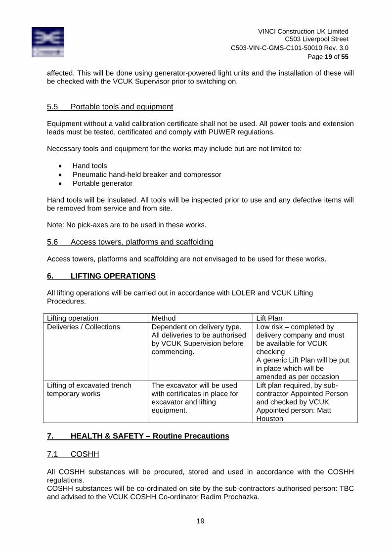
VINCI Construction UK Limited C503 Liverpool Street
C503-VIN-C-GMS-C101-50010 Rev. 3.0 Page 19 of 55
19
affected. This will be done using generator-powered light units and the installation of these will be checked with the VCUK Supervisor prior to switching on. 5.5 Portable tools and equipment Equipment without a valid calibration certificate shall not be used. All power tools and extension leads must be tested, certificated and comply with PUWER regulations. Necessary tools and equipment for the works may include but are not limited to:
Hand tools Pneumatic hand-held breaker and compressor Portable generator
Hand tools will be insulated. All tools will be inspected prior to use and any defective items will be removed from service and from site. Note: No pick-axes are to be used in these works. 5.6 Access towers, platforms and scaffolding Access towers, platforms and scaffolding are not envisaged to be used for these works. 6. LIFTING OPERATIONS All lifting operations will be carried out in accordance with LOLER and VCUK Lifting Procedures. Lifting operation Method Lift Plan Deliveries / Collections Dependent on delivery type.
All deliveries to be authorised by VCUK Supervision before commencing.
Low risk – completed by delivery company and must be available for VCUK checking A generic Lift Plan will be put in place which will be amended as per occasion
Lifting of excavated trench temporary works
The excavator will be used with certificates in place for excavator and lifting equipment.
Lift plan required, by sub-contractor Appointed Person and checked by VCUK Appointed person: Matt Houston
7. HEALTH & SAFETY – Routine Precautions 7.1 COSHH All COSHH substances will be procured, stored and used in accordance with the COSHH regulations. COSHH substances will be co-ordinated on site by the sub-contractors authorised person: TBC and advised to the VCUK COSHH Co-ordinator Radim Prochazka.

VINCI Construction UK Limited C503 Liverpool Street
C503-VIN-C-GMS-C101-50010 Rev. 3.0 Page 20 of 55
20
COSHH substances likely to be used for the works are: Diesel and Petrol Fuel Ready Mix concrete Hand mix concrete Machine greases Tarmac (bituminous coated road materials) Line marking paint Safety data sheets, and COSHH assessments are provided where available in Appendix 6, but as a minimum must be reviewed by the VCUK COSHH co-ordinator separately, and kept in the site file. Where COSHH assessments are required for the operations which were not planned at the time of this MS being compiled, the MS/RA must be reviewed by the sub-contractor and VCUK supervisor, to check no changes are required. Additional COSHH sheets will be produced and approved prior to works taking place. Lead paint: if any surfaces are excavated which are suspected of containing lead paint, the works will cease and advice sought from VCUK Supervisor. 7.2 Asbestos It is not envisaged that any asbestos exists in the ground where works are planned to take place. If asbestos is found or suspected to be found on-site, works will immediately stop, the site will be fenced off and cleared of all personnel. The VCUK Health and Safety Manager and VCUK Supervisor and Production Manager will need to be made aware immediately. Operatives may return to site only following instruction from VCUK Supervisor or Health and Safety Manager. 7.3 Excavations No excavation is to take place without a permit to penetrate being in place No excavations without appropriate access and edge protection All excavations require an assessment of temporary works requirements to take place, based
on the ground conditions. This can be authorised by any of the VCUK chartered civil engineers.
Potential for confined space hazards to be examined by competent person All excavations to be checked daily by sub-contractor’s appointed person and VCUK
Supervisor, and recorded Any defects to be immediately rectified Excavations required during this operation include: Trenches for the laying of utilities ducts in Blomfield Street, Eldon Street, New Broad Street,
Old Broad Street and Liverpool Street – approximately 400m in length; width will vary.
7.4 Manual Handling Manual handling should always be avoided by the use of mechanical means wherever reasonably practicable.

VINCI Construction UK Limited C503 Liverpool Street
C503-VIN-C-GMS-C101-50010 Rev. 3.0 Page 21 of 55
21
Personnel to be briefed on Manual Handling during toolbox talks and safety briefings. For any manual handling to take place, the person doing the manual handling, should ensure they have made an assessment of the operation, with the assistance of their supervisor if required. This assessment needs to reflect the nature of the load, where it needs to be handled to, the environment and the individual. Manual handling will be required for certain tasks, including: Transfer of ducts from the storing area to the remote worksites and installation of ducts and
bends Handling of the bedding material, concrete and tarmac Guidelines are as follows:
- Teams should ensure manual handling is shared between team members wherever possible to avoid repetitive strains on any individual
- Individuals should not attempt to lift loads that they cannot comfortably lift. - Individuals should not lift loads which exceed 20kg. - Individuals should not lift loads which are difficult to handle due to their size or shape. - Individuals should not lift heavy loads above shoulder height. - Multiple persons should not lift loads exceeding 20kg between them where the resulting
load carried by each person exceeds 20kg. - Appropriate rests should be taken to minimise strains due to repetitive lifting.
7.5 HAVs (Hand arm vibration) HAV-causing activities to be avoided wherever possible. Use of excavator machine for the works will be the preferred method and use of hand-held breakers will be avoided where possible. When hand-held breakers need to be used, for example near LU assets, suitable equipment will be chosen to minimise the risk of hand arm vibration. A HAV assessment must then be carried out by the sub-contractor, and provided to VCUK, with the aim of choosing the best machinery and limiting exposure to the individual by rotating operatives. Hand checks are required as a minimum for any person using vibrating tools, to be done daily by the subcontractor Supervisor. Assessment must also be made where operatives ride/sit in plant which is subject to vibration. Further control measures as part of a point of work Risk Assessment may be implemented as deemed necessary by the Site Supervisor. Sub-contractor and VCUK supervision to monitor daily for compliance as part of STARRT briefing. The following vibration activity risks have been identified: General minor drilling, cutting, fixing Breaking of ground with pneumatic hand held breakers – e.g. above LU assets is mandatory Full body vibration caused by excavator breaking ground 7.6 Occupational Noise Mandatory hearing protection zones will be established where noise exposure would otherwise exceed standard levels. Activities identified as being potentially noisy include:

VINCI Construction UK Limited C503 Liverpool Street
C503-VIN-C-GMS-C101-50010 Rev. 3.0 Page 22 of 55
22
Saw cutting of tarmac Breaking of ground (especially the concrete sub-base) using excavator or hand-held
breakers Fill compaction
7.7 Welfare facilities Site welfare is located within the Liverpool Street site compound. 7.8 PPE All PPE must be compliant to the appropriate British Standard. Advice can be sought from the VCUK H&S Manager: Tony Taylor. The PPE which will be used as standard for works around excavations is:
Steel toe capped and mid soled laced safety boots Hard hat (to comply with Crossrail policy below) Orange or Yellow Hi-Vis / Jacket Gloves Safety glasses Fire-retardant overalls
Crossrail hard hat policy is as follows.
Blue Hard Hats for Site Personnel White Hard Hat for Supervisors Orange Hard Hats for Banksman and Traffic Marshalls
In addition the following table outlines PPE which is expected to be worn for the following operations. As operations proceed the requirement for additional PPE must be reviewed, and the compatibility of PPE must be included in this review. Operation PPE Notes Concreting
Gauntlets Wellington boots Overalls Long sleeves Goggles
Mainly provide protection against burns during laying of concrete
Laying of tarmac Gauntlets Safety boots Overalls Long sleeves Goggles
Mainly provide protection against burns during laying of tarmac
Breaking of ground Shock resistant gloves Impact resistant goggles
Reduce risk of HAV and provide protection from flying debris
7.9 Safety equipment Acoustic barriers will be provided to minimise the noise for pedestrians and surrounding businesses.

VINCI Construction UK Limited C503 Liverpool Street
C503-VIN-C-GMS-C101-50010 Rev. 3.0 Page 23 of 55
23
7.10 Signs & Notices Access to the works will be controlled by VCUK as the Principal Contractor. Signs and notices will be provided in line with H&S regulations and best practice. Signage envisaged for these works includes: Danger Deep Excavations No unauthorised access Mandatory PPE – Hard Hat, Boots, Gloves, Eye Protection, Orange or Yellow Hi-visibility vest Mandatory hearing protection zones Emergency Exit Site Operatives will adhere to all existing signs and notices 7.11 First aid arrangements First aid facilities will be available on all sites, and the locations displayed on the site notice boards. These will be maintained by VCUK. First Aiders will be identified by a green cross on their helmets and on posters around the site. All subcontractors must provide suitably trained First Aiders for each of their working groups and a mobile first aid point if operating outside of the semi-permanent site compounds at Liverpool St, Blomfield St and Broad Street avenue. In the event of any injury (however minor), the first aid book must be completed and the site supervisor notified. 7.12 Fire Points Refer to the fire emergency plan and fire warden poster located on the RAMS board. Fire points will be located around the site in line with the site Fire Risk assessment. Fire Points will contain foam & CO2 fire extinguishers.
A competent person will inspect all fire fighting equipment periodically.
Additional coverage may be provided subject to the conditions of the hot works permit at the time of issue. For example, a hot works permit will be required for the laying of tarmac works.
7.13 Inclement weather
In the event of severe weather (i.e. wind/ rain/ snow), the VCUK Site Supervisor will assess the safety/ environmental implications that may arise due to the weather and will advise the VCUK Project Manager and temporarily cease the works if deemed necessary. The VCUK Project Manager will decide on the time period that works need to be ceased and what actions to be taken to secure vulnerable plant, equipment or materials and ensure the safety of all personnel. For example, in the event of high winds, temporarily cease works and remove acoustic blankets from heras fencing panels in order to reduce the wind load acting on the fence and therefore reduce the risk of the panels overturning.

VINCI Construction UK Limited C503 Liverpool Street
C503-VIN-C-GMS-C101-50010 Rev. 3.0 Page 24 of 55
24
7.14 Emergency In the event of an emergency, operatives are advised to:
Clear the area Raise the alarm Notify any of the VCUK site supervisors who will coordinate the emergency services and
facilitate first aid if appropriate. Emergency escape routes and assembly points are indicated on the RAMS board. Any changes to the assembly point will be notified in the STARRT briefing. In the event of an emergency, the VCUK supervisor will follow the Emergency Preparedness Plan. The emergency contact details for the utility companies will be available in section 7.15 of this document and in Appendix 1 of the Emergency Preparedness Plan. Both documents will be displayed on the project’s RAMS board. In the event of an emergency in an LU-affected area the LU Inspector will be the first point of contact on site for VCUK and their subcontractor. If the LU Inspector is not available at the time, a competent person i.e. VCUK Supervisor (VCUK Emergency Controller as per C503 Emergency Preparedness Plan) will take control of the event. The supervisor will notify the Vinci Safety Manager/Emergency Controller (Tony Taylor – 07816 517 070 or 02079 474 172) for assistance, who will ensure all incidents are reported on Crossrail’s RIVO system. If any accident, incident or dangerous occurrence occurs, all operatives shall remain at the Assembly Point until authorised to leave by the Vinci Site Manager. Investigations into incidents will be the responsibility of Vinci with the assistance of the site management.

VINCI Construction UK Limited C503 Liverpool Street
C503-VIN-C-GMS-C101-50010 Rev. 3.0 Page 25 of 55
25
Directions to Royal London Hospital, Whitechapel The nearest A&E Department is the Royal London Hospital, Whitechapel, London, E1 1BB. Telephone: 020 7377 7000

VINCI Construction UK Limited C503 Liverpool Street
C503-VIN-C-GMS-C101-50010 Rev. 3.0 Page 26 of 55
26 ms
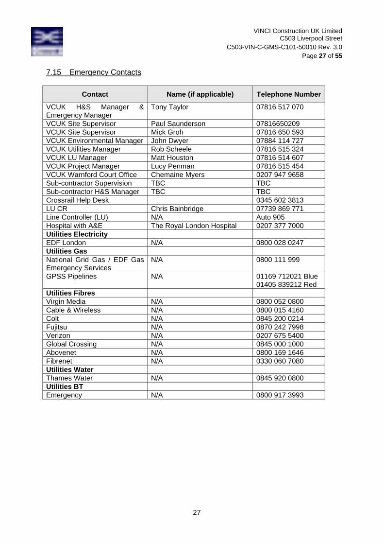
VINCI Construction UK Limited C503 Liverpool Street
C503-VIN-C-GMS-C101-50010 Rev. 3.0 Page 27 of 55
27
7.15 Emergency Contacts
Contact Name (if applicable) Telephone Number
VCUK H&S Manager & Emergency Manager
Tony Taylor 07816 517 070
VCUK Site Supervisor Paul Saunderson 07816650209 VCUK Site Supervisor Mick Groh 07816 650 593 VCUK Environmental Manager John Dwyer 07884 114 727 VCUK Utilities Manager Rob Scheele 07816 515 324 VCUK LU Manager Matt Houston 07816 514 607 VCUK Project Manager Lucy Penman 07816 515 454 VCUK Warnford Court Office Chemaine Myers 0207 947 9658 Sub-contractor Supervision TBC TBC Sub-contractor H&S Manager TBC TBC Crossrail Help Desk 0345 602 3813 LU CR Chris Bainbridge 07739 869 771 Line Controller (LU) N/A Auto 905 Hospital with A&E The Royal London Hospital 0207 377 7000 Utilities Electricity EDF London N/A 0800 028 0247 Utilities Gas National Grid Gas / EDF Gas Emergency Services
N/A 0800 111 999
GPSS Pipelines N/A 01169 712021 Blue 01405 839212 Red
Utilities Fibres Virgin Media N/A 0800 052 0800 Cable & Wireless N/A 0800 015 4160 Colt N/A 0845 200 0214 Fujitsu N/A 0870 242 7998 Verizon N/A 0207 675 5400 Global Crossing N/A 0845 000 1000 Abovenet N/A 0800 169 1646 Fibrenet N/A 0330 060 7080 Utilities Water Thames Water N/A 0845 920 0800 Utilities BT Emergency N/A 0800 917 3993

VINCI Construction UK Limited C503 Liverpool Street
C503-VIN-C-GMS-C101-50010 Rev. 3.0 Page 28 of 55
28
8. ENVIRONMENTAL PROTECTION 8.1 Waste management Sub-contractors will be required to manage all wastes produced.
Wastes expected to be produced in the course of the works include: General packaging General wastes associated with occupied site – paperwork, kitchen waste, etc. Spoil from excavations Hazardous waste - residuals from concreting and tarmac laying works; contaminated land if
discovered on site No rubbish and surplus excavated materials arising from the works will be dumped on an area other than a public or private tip controlled or recognised by the Local Authority. Works will be in compliance with legislation including where appropriate the Control of Substances Hazardous to Health Regulations (COSHH) 1988, HSE Guidance Note EH 40/90, Occupational Exposure Limits 1990 and any amendments thereto, governing the removal and controlled tipping of refuse. Where carting away is sub-let, it will require carriers to state the location of their proposed tipping areas and to provide proof that the rubbish has been deposited there.
No stock piling of any excavated spoil material will be permitted within the worksite except with the prior agreement with the VCUK Supervisor. Further requirements for the handling and disposal of contaminated materials are contained in the Waste Management Plan. Sampling will be undertaken to determine the nature of the material being removed from site. It is not envisaged that contaminated land exists in the areas of work but due to the proximity of the works to the burial ground discovered in Liverpool Street believed to be approximately 1.5m below ground level, if material believed to be contaminated is encountered (e.g. human remains, strong smelling soil) the following actions will be taken:
On the identification of contaminated land, stop works in the area and immediately, erect suitable fencing and appropriate safety signs enclosing the contaminated area;
Ensure no further work is undertaken in the area; Install any protective measures to nearby sensitive receptors (water courses, other
works etc); Notify the Site Supervisor, Production Manager and Environmental Manager; Identify measures required to prevent pollution; Once the site is secure, carry out testing of the contaminated land to determine the risk
to the type of construction work and/or the impact upon the environment; Undertake or amend risk assessments, and submit the risk assessments and revised
mitigation proposals to for acceptance; The type and extent of contamination will be identified and the material classified in
accordance with the Waste Acceptance criteria; Designated areas will be established so contaminated materials can be separated from
clean materials and stored appropriately. 8.2 Dust management Dust emissions will be monitored to confirm that they remain below the limit specified in Section 61. For the duration of the breaking the ground works, light damping down will take place unless weather conditions allow otherwise i.e. heavy rain removes the need for damping down.

VINCI Construction UK Limited C503 Liverpool Street
C503-VIN-C-GMS-C101-50010 Rev. 3.0 Page 29 of 55
29
8.3 Noise management Best practicable means as defined in the Section 61 consents and operative noise awareness (no shouting) will be employed to ensure noise levels are kept at reasonable levels. All people involved in this particular operation should be aware that the standard Section 61 working hours are 8am-6pm Monday to Friday, 8am-1pm Saturday. Work outside of these hours will not take place without a variation to the S61 consent, and the VCUK Supervisor having briefed the team on any conditions. Noise or vibration levels shall not exceed levels permitted under the Section 61 consent in place for the works. The trigger levels contained therein are to be adhered to at all times, and any case where noise exceeds these levels should be reported immediately. Different noise trigger levels will apply for different time periods with the normal working hours being at 75 dB over a 12hr period. As per the Noise Trigger Action Plan for 100 Liverpool Street document, works taking place in the proximity of the 100 Liverpool street building (Eldon Street, Liverpool Street, Old Broad Street and Blomfield Street.) must not exceed noise level of 79 dB over a 1hr period.
Acoustic blankets will be installed on the heras fencing during the breaking of the ground works in order to reduce the noise levels produced. The noise reduction capability is approximately 15dB at 1m from the blankets.
Ad-hoc noise monitoring will be undertaken throughout the works, in line with the S61 consent in addition to strategic semi-permanent noise monitors. 8.4 Vibration management No significant vibration risks are expected by these works. 8.5 Archaeology There is known archaeology throughout the Liverpool Street area, including human remains and Roman artefacts. Although the depth of the utility diversions is not anticipated to produce any significant archaeological finds, it should be noted that the area has yielded artefacts at shallow depths. MOLA (Museum of London Archaeology) will be available for a general watching brief and any finds or suspected finds will be highlighted immediately, and works stopped. In particular, if MOLA are not available for any reason, human remains will be covered again. For the works in Liverpool Street itself and the surrounding area, any excavations where archaeology is expected will have a watching brief. In all other areas operatives should be alert to the potential of encountering archaeological materials and report any occurrences. For any excavations in potential burial sites, the risk assessment reflects this and requires the following controls: Training for operatives on existing conditions and potential finds Washing facilities Good hygiene regime 8.6 Groundwater and surface water runoff VCUK Supervisors will ensure drains on the sites to be worked on are marked on a drainage plan to be displayed on site. Sub-contractor supervisors to be aware of drainage and ensure:

VINCI Construction UK Limited C503 Liverpool Street
C503-VIN-C-GMS-C101-50010 Rev. 3.0 Page 30 of 55
30
Discharge into drains is in accordance with best practice Discharge volumes do not exceed consent applications Emergency spill kits will be readily available on site in case of a fuel spillage during the works. Drip trays will be provided for refuelling of mobile plant and for preventing spills on smaller items of plant and equipment. Road gullies will be protected with hessian sandbags from all run-off affected by the works and there will be no discharge to the sewer system without the required consent from Thames Water. Measures required for concrete wagon wash out include discharging into the site settlement tank or a concrete wash out skip to prevent ground contamination.

VINCI Construction UK Limited C503 Liverpool Street
C503-VIN-C-GMS-C101-50010 Rev. 3.0 Page 31 of 55
31
APPENDIX 1) OPERATIONAL RISK ASSESSMENT (MS Ref: C503-VIN-C-GMS-C101-50010 rev 2.0)
ACTIVITY HAZARDOUS EVENT PERSONS AT RISK UNCONTROLLED RISK
RISK CONTROL MEASURES RESIDUAL RISK
P S Risk P S Risk
Working in close proximity to moving traffic
Services struck by errant vehicle causing loss of services function, explosion, fire, delay to traffic network
Operatives carrying out the works, the public and surrounding properties/businesses
2 5 10 - Traffic management measures in place prior to
commencement of works - Signage and fencing off of works
1 5 5
Use of mechanical plant
Incorrect use and/or unsuitable equipment causing damage to property
Property owners and users 2 3 6
- Site Briefing, Tool Box Talks, Supervision - Plant Certification, Trained Operatives (CPCS) - Use of banksmen, traffic marshals, traffic
management.
1 3 3
Working around live services
Striking live services causing damage to service provision
Surrounding properties 2 4 8
- Service records on site - Permit to penetrate and permit to dig in place - CAT scan of area prior to and throughout
excavation by a competent NRSWA trained person - Hand dig within 500mm of known or suspected
services - Good supervision - Visibly mark services on ground
1 4 4
Working above LU assets
Damage to LU assets from plant or tools
LU staff / customers and assets 3 5 15
- Hand dig only within 6m of LU assets - LU Supervisor on site to discuss works and mark
out location of LU assets - MS approved by LU
1 5 5
Transfer of concrete from mixing site to remote site
Spillage of concrete on highway causing pollution and damage to highway and vehicles
Public 3 3 9
- The dumper will only be partly filled - The banksman accompanying the dumper will be
aware of the concrete spillage risk and should inform the site supervisor if there is any spillage in order to have the highway cleaned
2 3 6

VINCI Construction UK Limited C503 Liverpool Street
C503-VIN-C-GMS-C101-50010 Rev. 3.0 Page 32 of 55
32
Originator (Subcontractor Engineer)
Signed …………………………………….…
Date……….……..……..
Originator (Subcontractor Manager)
Signed …………………………………….…
Date……….……..……..
CHECKED BY Tick VCUK Engineer (Low Risk 1 to 4)
Matt Houston/ Rob Scheele (Medium Risk 5 to 15)
Signed ………………………………………. Date……………………..
Project Manager/H&S Manager (High Risk 20 to 25 )
Signed ……………………………………….
Date………..……………

VINCI Construction UK Limited C503 Liverpool Street
C503-VIN-C-GMS-C101-50010 Rev. 3.0 Page 33 of 55
33
APPENDIX 2) OPERATIVE AND THIRD PARTY RISK ASSESSMENT (MS Ref: C503-VIN-C-GMS-C101-50010 rev 2.0)
ACTIVITY HAZARDOUS EVENT PERSONS AT RISK
UNCONTROLLED RISK
RISK CONTROL MEASURES RESIDUAL RISK
P S Risk P S Risk
Lone working Accident or incident involving site operatives Operatives 4 5 20
- During the works operatives will not be permitted to work alone
- All gangs to ensure no member of the team is left working at end of shift or at break times
2 5 10
Leptospirosis (rats) Psittacosis (pigeons)
Illness caused by the disease Operatives 2 5 10
- Operative briefing - Avoid working in areas of standing water. - Use correct PPE and wash hands and face before
eating, drinking or smoking. - Ensure work areas are clear of pigeon waste prior to
start
1 5 5
Slips trips and falls Injury Operatives 3 4 12 - Good housekeeping
- Operatives to remain vigilant 2 4 8
Working at height
Fall into excavation causing serious injury or fatality
Operatives 2 5 10
- Work only to take place where edge protection is in place.
- Signage to be in place warning of excavations - Operatives to remain within worksite limits set by
PM.
1 5 5
Excavation Excavation collapse causing serious injury or fatality
Operatives 3 5 15
- Temporary works design will be checked by VCUK Temporary Works Coordinator
- Inspections will be carried out by a competent person at the start of every shift and after any event.
- Adequate ground support will be installed where required
- Visual inspections throughout the shift and recording of excavation and temporary works condition
1 5 5
Working in close proximity to moving traffic
Operatives struck by errant vehicle causing serious injury or fatality
Operatives 3 5 15
- Traffic management measures in place prior to commencement of works
- Signage will be provided to ensure pedestrians and vehicles are clear on diverted routes.
- Toolbox talks
1 5 5

VINCI Construction UK Limited C503 Liverpool Street
C503-VIN-C-GMS-C101-50010 Rev. 3.0 Page 34 of 55
34
Use of mechanical plant
Incorrect use and/or unsuitable equipment causing serious injury or fatality
Operatives and/or members of public 2 5 10
- Site Briefing, Tool Box Talks, Supervision - Plant Certification, Trained Operatives (CPCS) - Use of banksmen, traffic marshals, traffic
management. - Additional task specific PPE: shock resistant gloves,
impact resistant goggles, ear defenders
1 5 5
Use of portable tools
Moving parts, incorrect use and/or unsuitable equipment causing: 1. Cuts, nips entanglement, eye injuries to operatives 2. Electrical shock, Electrocution
Operatives
2
2
4
5
8
10
- Use in accordance with manufacturers’ instructions - PAT testing procedures, Tool Box talks, Supervision - Use insulated tools - Additional task specific PPE: impact resistant
goggles
1
1
4
5
4 5
Unauthorised access to the site
Fall into excavation, struck by plant, slip and trips causing serious injury or fatality
Members of the public 3 5 15
- No members of the public will be allowed access to the sites
- Fencing and signage in place - Pedestrian exclusion zone will be erected where
possible by means of pedestrian barriers. - Pre-route inspection prior to manoeuvring,
appointed traffic Marshal to be in place.
1 5 5
Manual handling
Handling tools and materials with no manual handling assessment in place and insufficient guidance causing serious injury
Operatives 3 4 12
- Avoid manual handling where possible and use mechanical aids.
- Conduct specific manual handling assessment for each occasion identifying appropriate PPE to be used
- Guidance, Toolbox talks, Supervision - Conformance with Manual Handling Operations
Regulations
1 4 4

VINCI Construction UK Limited C503 Liverpool Street
C503-VIN-C-GMS-C101-50010 Rev. 3.0 Page 35 of 55
35
Working around live services
Striking live services causing serious injury or fatality
Operatives 5 5 25
- Service records on site - Permit to penetrate and permit to dig in place - CAT scan of area prior to and throughout the
excavation works by a competent trained person - Hand dig around known or suspected services - Use of insulated tools - CAT scan as excavation progresses - Good Supervision - Visibly mark services on ground
2 5 10
Mixing and placing of concrete
Use of incorrect procedures causing serious injury including concrete burns or blindness
Operatives 3 4 12
- Only trained and competent operatives to work with concrete
- Task specific PPE: gauntlets, Wellington boots, overalls, long sleeves, goggles to be used
1 4 4
Placing of tarmac
Use of incorrect procedures causing serious injury, burns to the operatives
Operatives 3 4 12 - Only trained and competent operatives to work with
tarmac - Task specific PPE: gauntlets, Safety boots, overalls,
long sleeves, goggles to be used
1 4 4
Use of hand-held vibration generating tools (i.e. hand-held breakers)
Exposure to high levels of vibration causing serious injury including Hand Arm Vibration
Operatives 5 4 20
- Avoid use of hand-held breakers when possible - Ensure that hand held tools are vibration
dampened, regularly serviced and maintained. - Minimise exposure to individual operatives by
rotating the workforce and keeping an HAVS register
2 4 8
Breaking the ground works
Flying debris produced causing serious injury or blindness
Operatives and public 5 4 20
- Exclusion zones will be put in place to protect operatives from flying debris during breaking operations using heras fencing and debris netting.
- Operatives taking part in the breaking operations to wear impact resistant goggles.
2 4 8
Breaking the ground works
High noise levels produced causing serious injury
Operatives 5 3 15
- Operatives taking part in the breaking operations will need to wear appropriate ear protection
- Area of works will be established as ear protection zone where ear protection PPE will be mandatory for all people.
2 3 6

VINCI Construction UK Limited C503 Liverpool Street
C503-VIN-C-GMS-C101-50010 Rev. 3.0 Page 36 of 55
36
Encounter archaeological materials during excavations
Disease or illness to operatives Operatives 3 3 9
- Training for operatives on existing conditions and potential finds
- Washing facilities - Good hygiene regime - Toolbox talks
1 3 3
Vehicle movements around the site
Operatives struck by moving plant causing serious injury or fatality
Operatives 4 5 20
‐ All unnecessary personnel to be excluded from the area with barriers, segregation of plant and pedestrians
‐ A person will be stationed to direct unnecessary personnel away from the operations
‐ Safety and traffic management signage will be in place
‐ A banksman will be on site all the time
2 5 10
UXO Exposure of unexploded ordnance causing serious injury or fatality
Operatives 2 5 10 ‐ Operative briefing, Toolbox talks ‐ Evacuate site if UXO found or suspected to be
found 1 5 5
Lifting activities Use of incorrect procedures causing serious injury
Operatives 4 4 16
‐ Operative briefing, Toolbox talks ‐ Lifting activities to be undertaken as per the specific
approved Lifting Plan that will be in place for the works
‐ Plant to be operated by competent people ‐ All unnecessary personnel to be excluded from the
area with barriers, segregation of plant and pedestrians
2 4 8

VINCI Construction UK Limited C503 Liverpool Street
C503-VIN-C-GMS-C101-50010 Rev. 3.0 Page 37 of 55
37
Originator (Subcontractor Engineer)
Signed …………………………………….…
Date……….……..……..
Originator (Subcontractor Manager)
Signed …………………………………….…
Date……….……..……..
CHECKED BY
Tick
VCUK Engineer (Low Risk 1 to 4)
Matt Houston/ Rob Scheele (Medium Risk 5 to 15)
Signed ………………………………………. Date……………………..
Project Manager/H&S Manager (High Risk 20 to 25 )
Signed ……………………………………….
Date………..……………
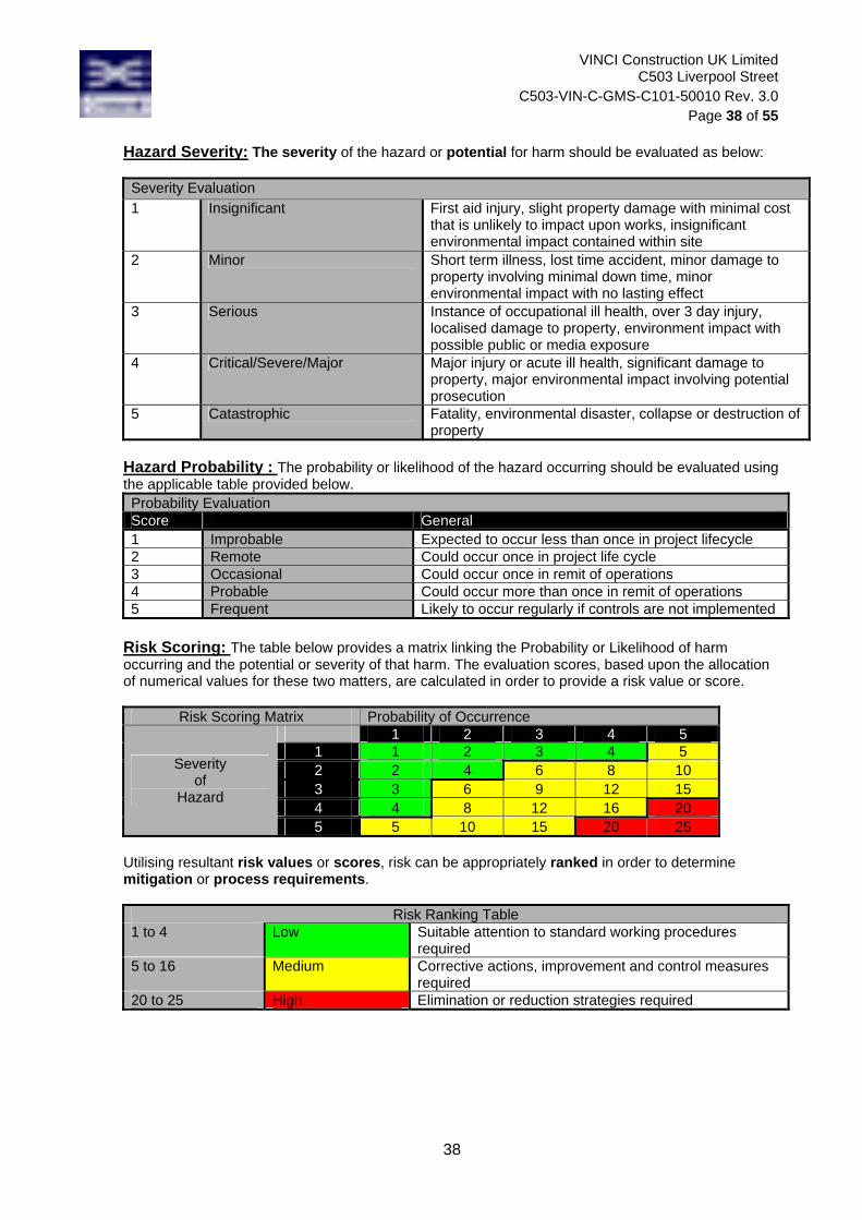
VINCI Construction UK Limited C503 Liverpool Street
C503-VIN-C-GMS-C101-50010 Rev. 3.0 Page 38 of 55
38
Hazard Severity: The severity of the hazard or potential for harm should be evaluated as below: Severity Evaluation 1 Insignificant First aid injury, slight property damage with minimal cost
that is unlikely to impact upon works, insignificant environmental impact contained within site
2 Minor Short term illness, lost time accident, minor damage to property involving minimal down time, minor environmental impact with no lasting effect
3 Serious Instance of occupational ill health, over 3 day injury, localised damage to property, environment impact with possible public or media exposure
4 Critical/Severe/Major Major injury or acute ill health, significant damage to property, major environmental impact involving potential prosecution
5 Catastrophic Fatality, environmental disaster, collapse or destruction of property
Hazard Probability : The probability or likelihood of the hazard occurring should be evaluated using the applicable table provided below. Probability Evaluation Score General 1 Improbable Expected to occur less than once in project lifecycle 2 Remote Could occur once in project life cycle 3 Occasional Could occur once in remit of operations 4 Probable Could occur more than once in remit of operations 5 Frequent Likely to occur regularly if controls are not implemented
Risk Scoring: The table below provides a matrix linking the Probability or Likelihood of harm occurring and the potential or severity of that harm. The evaluation scores, based upon the allocation of numerical values for these two matters, are calculated in order to provide a risk value or score.
Risk Scoring Matrix Probability of Occurrence
Severity of
Hazard
1 2 3 4 5 1 1 2 3 4 5 2 2 4 6 8 10 3 3 6 9 12 15 4 4 8 12 16 20 5 5 10 15 20 25
Utilising resultant risk values or scores, risk can be appropriately ranked in order to determine mitigation or process requirements.
Risk Ranking Table 1 to 4 Low Suitable attention to standard working procedures
required 5 to 16 Medium Corrective actions, improvement and control measures
required 20 to 25 High Elimination or reduction strategies required

VINCI Construction UK Limited C503 Liverpool Street
C503-VIN-C-GMS-C101-50010 Rev. 3.0 Page 39 of 55
39
APPENDIX 3
Drawings and Sketches
Site Boundary drawing Crossrail lorry routes drawing LU Assets

VINCI Construction UK Limited C503 Liverpool Street
C503-VIN-C-GMS-C101-50010 Rev. 3.0 Page 40 of 55
40

VINCI Construction UK Limited C503 Liverpool Street
C503-VIN-C-GMS-C101-50010 Rev. 3.0 Page 41 of 55
41
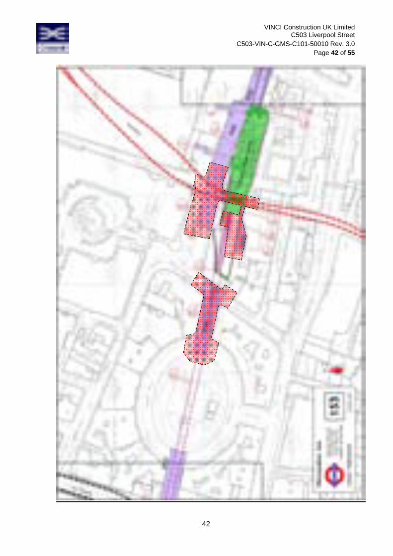
VINCI Construction UK Limited C503 Liverpool Street
C503-VIN-C-GMS-C101-50010 Rev. 3.0 Page 42 of 55
42

VINCI Construction UK Limited C503 Liverpool Street
C503-VIN-C-GMS-C101-50010 Rev. 3.0 Page 43 of 55
43
APPENDIX 4
Lifting operation plan
The lifting operation plan is currently under development. Lifting operations will not commence until an approved by VCUK lifting operation plan is in place.

VINCI Construction UK Limited C503 Liverpool Street
C503-VIN-C-GMS-C101-50010 Rev. 3.0 Page 44 of 55
44
APPENDIX 5
Temporary works
The temporary works design is currently under development. Excavation works will not proceed past the point where any temporary works are required until an approved temporary works design is in place.
Note: VCUK retain copies of design calculations and design check certificate

VINCI Construction UK Limited C503 Liverpool Street
C503-VIN-C-GMS-C101-50010 Rev. 3.0 Page 45 of 55
45
APPENDIX 6
COSHH, HAVs, Occupational noise and manual handling assessments
COSHH sheets available for:
o Diesel fuel/gas oil
o Ready Mix concrete
o Bituminous coated road materials
o Line marking paint
o Aggregates
o Cement and Mortar containing cement
HAVs – subcontractor to provide HAV assessment for all operatives
Occupational noise – subcontractor to provide occupational noise assessment for all operatives
Manual handling - subcontractor to provide manual handling assessment for all operatives

VINCI Construction UK Limited C503 Liverpool Street
C503-VIN-C-GMS-C101-50010 Rev. 3.0 Page 46 of 55
46
COSHH HAZARD & RISK ASSESSMENT SHEET
No.: 1
SUBSTANCE/PRODUCT NAME AND DESCRIPTION: DIESEL FUEL/GAS OIL Colour varies according to taxation - odour is typical hydrocarbon.
HAZARDOUS CONTENT COMMENTS CLASSIFICATION Hydrocarbon mixture
See EH40 appendix 5 Reduce exposure to as low as reasonably practicable.
Risk Phrase - R45 May Cause Cancer Irritant Flammable
HOW IS SUBSTANCE SUPPLIED, USED? Can be supplied in bulk or decanted into 45 gal. drums and smaller containers. Drums should be on a stillage with tap fitted to minimise spillage and contact with the skin. Suitable containers should be used to fill vehicles using funnels etc to minimise spillage. Tanks must be double skinned or bunded with a proper dispensing hose, isolating valve and lock. ASSESSMENT OF RISK, AND PRECAUTIONS TO BE TAKEN Low risk when used as above. Gloves should be used and splashes to the skin washed off - prolonged skin contact can cause dermatitis. Long term exposure to this product carries a cancer risk. The PPE indicated below should be worn when working with this substance in the manner described. If site rules state other PPE must be worn at all times then the rules must be adhered to as well as the following recommendations.
Eye
Protection must be
worn
Safety footwear must be
worn
Ear defenders must be
worn
Gloves must be
worn
Face Masks
must be worn
Respirators must be
worn
Protective clothing must be
worn FIRST AID INFORMATION AND EMERGENCY ACTIONS Eyes - Irrigate with plenty of water Skin – Remove splashes from the skin ASAP. Wash with soap and water Inhalation - Remove to fresh air Ingestion - Seek medical assistance, drink copious amounts of water, do not induce vomiting. Spillage management - Eliminate sources of ignition. Contain spillage in booms or sand or absorbents. Place recovered material in labelled container for disposal. NB: If the product is being used in a manner different from the way described above, a separate risk assessment will be needed
VINCI Construction UK Limited C503 Liverpool Street
C503-VIN-C-GMS-C101-50010 Rev. 3.0 Page 47 of 55
47
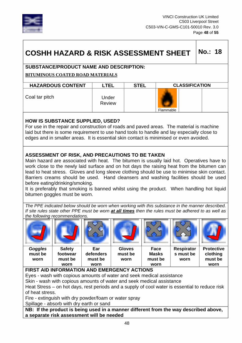
VINCI Construction UK Limited C503 Liverpool Street
C503-VIN-C-GMS-C101-50010 Rev. 3.0 Page 48 of 55
48
COSHH HAZARD & RISK ASSESSMENT SHEET
No.: 18
SUBSTANCE/PRODUCT NAME AND DESCRIPTION: BITUMINOUS COATED ROAD MATERIALS
HAZARDOUS CONTENT LTEL STEL CLASSIFICATION Coal tar pitch
Under Review
Flammable HOW IS SUBSTANCE SUPPLIED, USED? For use in the repair and construction of roads and paved areas. The material is machine laid but there is some requirement to use hand tools to handle and lay especially close to edges and in smaller areas. It is essential skin contact is minimised or even avoided. ASSESSMENT OF RISK, AND PRECAUTIONS TO BE TAKEN Main hazard are associated with heat. The bitumen is usually laid hot. Operatives have to work close to the newly laid surface and on hot days the raising heat from the bitumen can lead to heat stress. Gloves and long sleeve clothing should be use to minimise skin contact. Barriers creams should be used. Hand cleansers and washing facilities should be used before eating/drinking/smoking. It is preferably that smoking is banned whilst using the product. When handling hot liquid bitumen goggles must be worn. The PPE indicated below should be worn when working with this substance in the manner described. If site rules state other PPE must be worn at all times then the rules must be adhered to as well as the following recommendations.
Goggles must be
worn
Safety footwear must be
worn
Ear defenders must be
worn
Gloves must be
worn
Face Masks
must be worn
Respirators must be
worn
Protective clothing must be
worn FIRST AID INFORMATION AND EMERGENCY ACTIONS Eyes - wash with copious amounts of water and seek medical assistance Skin - wash with copious amounts of water and seek medical assistance Heat Stress – on hot days, rest periods and a supply of cool water is essential to reduce risk of heat stress. Fire - extinguish with dry powder/foam or water spray Spillage - absorb with dry earth or sand NB: If the product is being used in a manner different from the way described above, a separate risk assessment will be needed

VINCI Construction UK Limited C503 Liverpool Street
C503-VIN-C-GMS-C101-50010 Rev. 3.0 Page 49 of 55
49
COSHH HAZARD & RISK ASSESSMENT SHEET
No.:
SUBSTANCE/PRODUCT NAME AND DESCRIPTION: LINE MARKING PAINT
HAZARDOUS CONTENT LTEL STEL CLASSIFICATION Xylene, dichloromethane acrylic resin
100 ppm
150 ppm
Flammable Harmful HOW IS SUBSTANCE SUPPLIED, USED? Supplied in aerosol containers varying from 500ml to 750ml ASSESSMENT OF RISK, AND PRECAUTIONS TO BE TAKEN There is a Medium risk to health when working for long periods with aerosol line marking paint. Extremely flammable Harmful by inhalation and in contact with skin Limited evidence of a carcinogenic effect Irritating to skin May be harmful in ingested in quantity May cause eye irritation Do not breathe aerosol When using, do not eat, drink or smoke Avoid contact with skin and eyes The PPE indicated below should be worn when working with this substance in the manner described. If site rules state other PPE must be worn at all times then the rules must be adhered to as well as the following recommendations.
Eye
Protection must be
worn
Safety footwear must be
worn
Ear defenders must be
worn
Gloves must be
worn
Face Masks
must be worn
Respirators must be
worn
Protective clothing must be
worn FIRST AID INFORMATION AND EMERGENCY ACTIONS Eye contact - wash with copious amounts of water. If irritation persists seek medical assistance Skin contact - wash with hand cleanser - use gloves and or barrier creams Ingestion – do not induce vomiting, give plenty of water in sips, seek medical attention Inhalation - move to fresh air - seek medical attention

VINCI Construction UK Limited C503 Liverpool Street
C503-VIN-C-GMS-C101-50010 Rev. 3.0 Page 50 of 55
50
Spillage Not applicable when intact In case of leakage or loss of containment: Ventilate area and exclude all sources of ignition Wear protective clothing if whole container is split Allow to dissipate Ensure area is safe before re-entry Fire Isolated small scale fire Water fog – carbon dioxide – powder – foam Do not use water jet Large fire: evacuate area, call fire brigade or follow site procedure Wear self-contained breathing apparatus and protective clothing Toxic fumes are produced when substance is involved in a fire Keep aerosol cans cool, do not burn for disposal Risk of explosion if involved in a fire NB: If the product is being used in a manner different from the way described above, a separate risk assessment will be needed

VINCI Construction UK Limited C503 Liverpool Street
C503-VIN-C-GMS-C101-50010 Rev. 3.0 Page 51 of 55
51
COSHH HAZARD & RISK ASSESSMENT SHEET
No.: 9
SUBSTANCE/PRODUCT NAME AND DESCRIPTION: AGGREGATES Crushed rock, sand and gravel aggregates
HAZARDOUS CONTENT LTEL STEL CLASSIFICATION Quartz (Silica) Total dust - this is a Maximum Exposure Limit Quartz (Silica) Respirable dust
0.3mgm³ 0.1mgm3
Irritant Harmful
HOW IS SUBSTANCE SUPPLIED, USED? Delivered in bulk and tipped from lorry. Basic construction material for filling and levelling or laying of roads and drives. Small quantities are shovelled, large quantities are moved using machines. Depending on the rock type the hazard will vary. If the rock type is rich in silica there could be some free silica in the dust. If the rock type is limestone risk is eliminated. With all types minimise exposure to dust by staying upwind of tipping operations and so out of any dust. If there is a lot of dust use water sprays to suppress and control.. ASSESSMENT OF RISK, AND PRECAUTIONS TO BE TAKEN Risk to health from inhalation of dust is not significant, as personnel normally stand up-wind of delivery vehicle during tipping operations and exposure time is very short. In very dry weather spray aggregates with water to suppress dust. Respirators may be provided (BS EN 149) to personnel working in poorly ventilated areas when tipping or handling. The PPE indicated below should be worn when working with this substance in the manner described. If site rules state other PPE must be worn at all times then the rules must be adhered to as well as the following recommendations.
Eye
Protection must be
worn
Safety footwear must be
worn
Ear defenders must be
worn
Gloves must be
worn
Face Masks
must be worn
Respirators may be
worn
Protective clothing must be
worn FIRST AID INFORMATION AND EMERGENCY ACTIONS Eyes - irrigate with copious amounts of water for 15 minutes. If irritation persists seek medical advice. Skin - Wash with soap and water before meals. NB: If the product is being used in a manner different from the way described above, a separate risk assessment will be needed

VINCI Construction UK Limited C503 Liverpool Street
C503-VIN-C-GMS-C101-50010 Rev. 3.0 Page 52 of 55
52
COSHH HAZARD & RISK ASSESSMENT SHEET No.: 14 SUBSTANCE/PRODUCT NAME AND DESCRIPTION: CEMENT and MORTAR containing cement. Dry mixture of Calcium Silicate/Alumina/Gypsum mixed with water.
HAZARDOUS CONTENT LTEL STEL CLASSIFICATION Calcium Silicate Total dust Calcium Silicate Respirable dust Chromium as Chromium vi.
10mg m³ 4mg m³ 0.05 mg m³
MEL
Risk Phrase 43 – May cause sensitisation
Irritant HOW IS SUBSTANCE SUPPLIED, USED? Supplied preferably in 25 Kg sacks though 50Kg sacks are still available but these can cause manual handling problems. Mixed on site for mortars, concrete and other bonding agents. At present cement does contain more than 2ppm (typically 15ppm) chromium vi present in the raw materials, and as such packaging must carry the warning – May cause allergic reaction or risk phrase R43. As of 15th January 2005, all cement produced in UK will have the chromium vi content reduced to less that 2 ppm, (to comply with new EU standards). ASSESSMENT OF RISK, AND PRECAUTIONS TO BE TAKEN Wet cement releases strong alkalis which can cause irritant dermatitis, burns and damage to eyes. Because of the chromium vi content, there is also a risk of allegoric dermatitis. This risk will be significantly reduced when the content is reduced to below 2ppm. Skin contact and eye contact should be minimised or avoided by using PPE. Inhaling small quantities does not present a significant health risk. Use P.P.E. such as gloves and long sleeved clothing to minimise skin contact is required. If wet mixing or in windy conditions wear light eye protection. Good washing facilities with warm water soap and towels are essential. It is important to wash cement and mortar off the skin as soon as practicable. The PPE indicated below should be worn when working with this substance in the manner described. If site rules state other PPE must be worn at all times then the rules must be adhered to as well as the following recommendations.
Eye Protection must be
worn if wet mixing or
windy
Safety footwear must be
worn
Ear defenders must be
worn
Gloves must be
worn
Face Masks
must be worn
Respirators must be
worn
Protective clothing must be
worn
FIRST AID INFORMATION AND EMERGENCY ACTIONS Skin - wash off any splashes on the skin immediately using soap and warm water Eyes - splashes in eyes should be treated with copious amounts of water for 15 minutes. If irritation persists seek immediate medical assistance. NB: If the product is being used in a manner different from the way described above, a separate risk assessment will be needed

VINCI Construction UK Limited C503 Liverpool Street
C503-VIN-C-GMS-C101-50010 Rev. 3.0 Page 53 of 55
53
Appendix 7: Briefing Sheets
STARRT Briefing Safety Task Analysis Risk Reduction Talk STARRT Contract: ………………………………………………………………………… Date: ……………………………. Time: …………………………… Supervisor (Print Name): ………………………………………………………. Contractor - Subcontractor (Print): ……………………………………………. Job Description: YES NO 1) Safety Planning - Checklist (Supervisor) a) Method Statement/Risk assessment received and understood ……… ………. b) Employees suitable & competent ……… ………. c) Materials suitable ……… .……… d) Tools/Equipment suitable ……… ………. 2) Task Briefing a) Toolbox talk given ……… ………. 3) Safety Checklist (Employee) a) Task instruction received and understood ……… ………. b) Risk assessment control measures received and understood ……… ……… c) PPE suitable for task and issued ……… ……… d) Emergency action received and understood ……… ……… e) Tools & equipment issued and in good order ……… ……… f) Housekeeping requirements understood ……… ……… Note: Any ‘no’ answers and operation must not proceed without authorisation from Works Manager Commitment I/we will stop work and report if operation becomes unsafe I/we will ensure all involved follow safety rules I/we accept responsibility for health and safety and environmentally acceptable behaviour for myself and my co-workers during this task Employee Signature: …………………………………………………………………………………….. Suggestions for improved health and safety and environmental performance: ………………………………………………………………………………………………………………… ………………………………………………………………………………………………………………… …………………………………………………………………………………………………………………

VINCI Construction UK Limited C503 Liverpool Street
C503-VIN-C-GMS-C101-50010 Rev. 3.0 Page 54 of 55
54
Safety Task Analysis Risk Reduction Talk STARRT Purpose To establish to procedure for systematically identifying all the hazards/risks associated with a task or job and to implement appropriate control measures. STARRT compliments any existing controls for the assessment of Health and Safety risks and the identification of the preventative and protective measures. Scope The STARRT process applies to all Vinci Construction UK employees who work on the project. STARRT takes the planning process one stage further by ensuring that the workers are briefed by their “ganger”/supervisors and that the workers have an opportunity to contribute to the process. The STARRT cards and their monitoring, form a record of the effectiveness of the process. Definitions Safety Task Analysis Risk Reduction Talk (STARRT) - a process that utilises employees to identify and resolve health and safety hazards associated with a task prior to it being performed. Foremen/Ganger - a work team’s front line supervisor who puts the job task team to work. STARRT Card - a two part card completed by the “ganger” and job task personnel before start of work which forms a record of the talk and action items. Requirements Foremen/Ganger will ensure: All employees under his/her charge are trained in the STARRT process. That there is a system to follow-up with all of his/her team to verify the STARRT process is being
correctly implemented. His/her employees participate in an individual STARRT review prior to the start of each shift for
each new task. That STARRT cards are reviewed for proper usage/completion by the Principal Contractor H&S
Supervisor and maintained on file for program review in their H&S Office.

VINCI Construction UK Limited C503 Liverpool Street
C503-VIN-C-GMS-C101-50010 Rev. 3.0 Page 55 of 55
55
Appendix 8 : Responsible Persons Contacts List Client Company: Crossrail Ltd Address: 25 Canada Square
Canary Wharf London E14 5LQ
Name: Hani Rizkallah Title Project Manager Tel 020 3229 9100 Email [email protected]
Client Responsible Manager Company: Crossrail Ltd Address: 25 Canada Square
Canary Wharf London E14 5LQ
Name: Matt White Title Tel 0203 329 9100 Email [email protected]
Designer Company Mott MacDonald Address: Mott MacDonald House
8-10 Sydenham Road Croydon CR0 2EE
Name: Alex Graham Title Tel 020 3229 9765 Email [email protected]
Principal Contractor Company Vinci Construction Ltd Address: Warnford Court
29 Throgmorton Street London EC2N 2AT
Name: Lucy Penman Title Project Manager Tel 07816 515 454 Email [email protected]
Principal Contractor: Work Manager Company Vinci Construction Ltd Address: Warnford Court
29 Throgmorton Street London EC2N 2AT
Name: Rob Scheele Title Construction Manager & LU Interface Manager Tel 07816 515 324 Email [email protected]
Contractor Company TBC Address: Name: Title Tel Email
Works Supervisor Company TBC Address: Name: Title Tel Email

Liverpool Street: Method Statement for Verizon works at Old Broad Street in relation to the Scheduled Monument – City Wall (LO26N)
Document uncontrolled once printed. All controlled documents are saved on the CRL Document System
© Crossrail Limited UNCONTROLLED
Appendix G Minutes from English Heritage Consultation (14 October 2011)

Liverpool Street: Method Statement for Verizon works at Old Broad Street in relation to the Scheduled Monument – City Wall (LO26N)
Document uncontrolled once printed. All controlled documents are saved on the CRL Document System
© Crossrail Limited UNCONTROLLED
Appendix H JB Riney Utility Trial Trench Report: Trial Hole Number 19, Old Broad Street
Liverpool Street Area – Trial Hole Number : 19 – Old Broad Street
Utility Trial Trench ReportFront Pages to be supplied by Client
Liverpool Street :Trial Hole No. 19Old Broad Street

Liverpool Street Area – Trial Hole Number : 19 – Old Broad Street
Utility Contacts ListElectricity Water
EDF (East of England) 0800 780078 Anglian water 0345 145145
EDF (South East) 0800 0963766 Bristol Water 0845 7023797
EDF 24 Seven 0800 780078 Essex Water 0845 7820999
Scottish & Southern 0345 708090 North Surrey 01784 426800
GPU Power 0845 7331331 Ext 6061 North West 0845 462200
Norweb 0800 1954141 South West 0800 1691144
Yorkshire Elec 0113 2415151 Southern Water 0845 2788045
Western Power 0800 365900 South East Water 0800 3010845
National Grid 0800 404090 South Staffs Water 0800 3891011
Seven Trent 0800 7834444
Gas/Oil Pipelines Three Valleys 01784 426800
Transco 0800 111999 Thames Water 0845 9200800
GPSS Pipelines 01169 712021 Blue 01405 839212 Red
Wessex Water 0845 6004600
Esso Pipelines 0800 800333 Yorkshire Water 0845 124 2424
Total/Fina 0800 592240
Fisher German 0800 136812 Telecoms
Fibres British Telecom 0800 917 3993
NTL/Telewest 0870 888 3116
C&W 0800 015 4160 Traffic
Colt 0845 200 0214 Transport for London 0207 126 1024
Energis 01322 295245 Trafficmaster 0870 5561 712
Easynet 0800 0277 277
Torch 0800 138 4858
Eurobell 01392 200222
Fujitsu 0800 435112
MK International (Worldcom) 0207 675 5400
THUS 0800 027 1280
NII 01924 508368

Liverpool Street Area – Trial Hole Number : 19 – Old Broad Street
Location
Liverpool –Old Broad Street Trial Hole No. 19
To the centre of trial hole:Easting : 533076Northing : 181479
24.0m

Liverpool Street Area – Trial Hole Number : 19 – Old Broad Street Property Boundary
2350mm 8850mm 2340mm
FootwayFootway
Not to scale
All measurements in MM, Utility
ownership is assumed only and should be verified
Property Boundary
Sectional view facing London Wall
10mmElectric
40
0
3360
3440
68
0
3660
61
0
4270
99
0
60
0
19
0
1990
2390
2590
2740
640
960
1650
1890
68
0
44
0
13
0
24
0
29
0
33
0
54
0
31
0
22
03
00
32
0
75
0
65
0
65
0
48
03660
3360
3090
1950
1700
1500
1600
1300
850
43
0
3860
4560
4760
75
0
40
0
British Telecom/THUS/Metro Media/Cable & Wireless
Colt / Energis / CATV / Verizon
Gas
EDF
Water
Unknown
5200
5360
5800
5010
5980
6590
69
0
36
06
00
58
0
69
05
90
5540
4640
4440
40
0
45
04
50
Leve
l of
dig
54
0m
m
Skylight AreaNot excavated
96mmBT
50mmMetro Media
110mmOrange
96mmBT
Bitumen SlabOver electric cables
Leve
l of
dig
85
0m
m
96mmBT
Leve
l of
dig
85
0m
m
110mmGreen
8” DuctileIron Water
Leve
l of
dig
84
0m
m
110mmGrey THUS
225 PEGas
Warning TapeOver electric
96mmGreen
7”Cast Water
6”Cast Unknown
Leve
l of
dig
15
00
mm
110mmGreen
110mmGreen
96mmGrey BT
110mm Grey BT
225 PEWater
2” Steel Electric4” Steel Electric
3” CastElectric
4” CastElectric
96mmBT Grey
Leve
l of
dig
48
0m
m
7” CastGas
Basement
96mmGreen
Leve
l of
dig
46
0m
m
Skylight AreaNot excavated
Picture 1 Picture 2 & 3 Picture 4 & 5 Picture 6

Liverpool Street Area – Trial Hole Number : 19 – Old Broad Street
Composition
Road Structure
Bituminous
Bound, 50
Concrete, 200
Crushed Brick
and Soil, 600
0
100
200
300
400
500
600
700
800
900
1000
1100
1200
1300
1400
1500
Surface Type : Bituminous Bound Material
Ground Conditions :
Ground water (m) : N/A
Excavation stopped (m) : 850mm
Ground Contamination : None
Tree Roots : None Found
Composition (m) :
0 – 50mm Bituminous Bound Materials
50 – 250mm Concrete
250 – 850mm Crushed Brick and Soil

Liverpool Street Area – Trial Hole Number : 19 – Old Broad Street
Pre-excavation Preparation
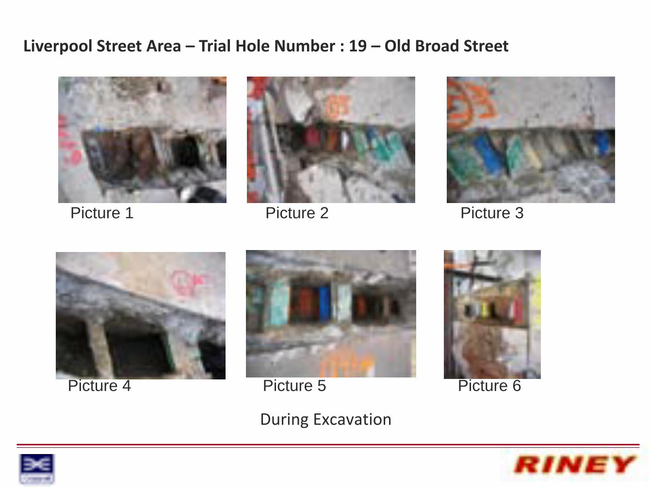
Liverpool Street Area – Trial Hole Number : 19 – Old Broad Street
During Excavation
Picture 1 Picture 2 Picture 3
Picture 4 Picture 5 Picture 6

Liverpool Street Area – Trial Hole Number : 19 – Old Broad Street
Excavated and Reinstated

Liverpool Street Area – Trial Hole Number : 19 – Old Broad Street
Health and Safety file information :
Description of Works Undertaken – Trial trench in carriageway and footway on 6, 7, 13 & 14/06/2009.
Residual Hazards – No contaminated ground or water table found.
As-Built Drawings – See main document.
Details of Construction Methodology and Materials – Machine assisted hand dig to 1.5m deep.
Details of Approved, Non-Standard or Alternative Materials used – Sand, type 1 roadstone, C40 concrete, Hot rolled asphalt.
Details of Highway Structures – See main document.
Operation & Maintenance – No maintenance.
Details and Location of Services or Apparatus Identified – See main document.