method of increasing the accuracy of an angular velocity meter
TRANSCRIPT
M E T H O D OF I N C R E A S I N G T H E A C C U R A C Y
OF AN A N G U L A R V E L O C I T Y METER
G. B. G u t m a n , V. I . R o l i c h , V. E. T r e t ' y a k o v , a n d Yu. V. F i l a t o v
UDC 531.77.088
An angular velocity meter consists of a ring laser, adding circuit, photoreceiver, and electronic measuring complex.
As is known [1], when a ring laser rotates around an axis perpendicular to the plane of a resonator, a difference frequency signal (beat signal) occurs whose frequency as a first approximation is proportional to the angular velo- city w:
Av = Ko,
where A v is the beat signal frequency; K = const is a coefficient dependent on the parameters of the ring laser.
It is obvious that some angular displacement of the resonator of the laser, which is constant for it, corresponds to the period of the beat signal. By determining the number of pulses during some (usually quite small, about 0.01 sec) dine interval At, we can measure the instantaneous value of angular velocity. Thus, measurement of angular velocity amounts to a determination of angle ~ through which the ring laser turns during a known time interval (in- terrogation time).
Since the time interval At can be assigned rather exactly (the relative error of quartz oscillators is 10 -7-10-8), the accuracy of measuring the angular velocity is determined by the accuracy with which the dependence Av = Kw is fulfilled for the ring laser. The ring laser used in the angular velocity meter should be calibrated, i.e., the period of the beat signal should correspond to the angular displacement of the resonator. Calibration can be ac- complished by turning the ring laser through some known fixed angle (in particular, one or several revolutions).
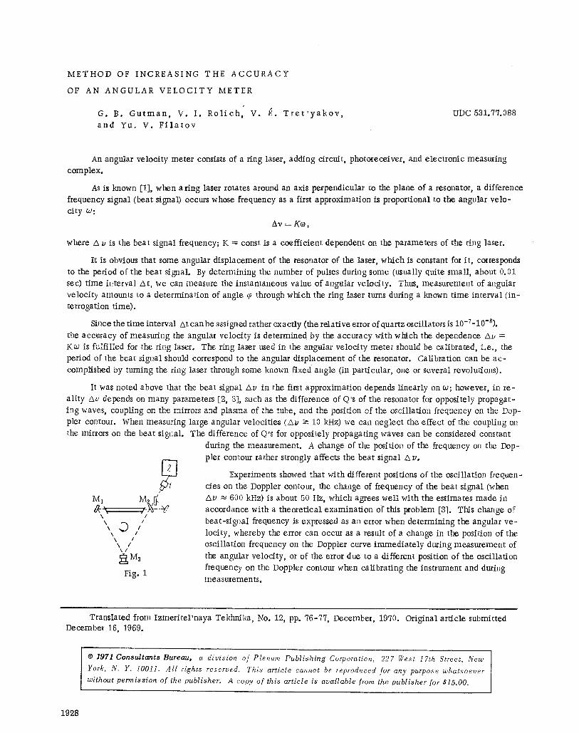
It was noted above that the beat signal a v in the first approximation depends linearly on w; however, in re- ality Av depends on many parameters [2, 3], such as the difference of Q's of the resonator for oppositely propagat- ing waves, coupling on the mirrors and plasma of the tube, and the position of the oscillation frequency on the Dop- pler contour. When measuring large angular velocities (Av --> 10 kHz) we can neglect the effect of the coupling on the mirrors on the beat signal. The difference of Q's for oppositely propagating waves can be considered constant
M1
\ / \ /
%. I \ I
\ / \ /
r
Fig. 1
during the measurement. A change of the position of the frequency on the Dop- pler contour rather strongly affects the beat signal /x v.
Experiments showed that with different positions of the oscillation frequen- cies on the Doppler contour, the change of frequency of the beat signal (when Av ~ 600 kHz) is about 50 Hz, which agrees well with the estimates made in accordance with a theoretical examination of this problem [3]. This change of beat-signal frequency is expressed as an error when determining the angular ve- locity, whereby the error can occur as a result of a change in the position of the oscillation frequency on the Doppler curve immediately during measurement of the angular velocity, or of the error due to a different position of the oscillation frequency on the Doppler contour when calibrating the instrument and during measurements.
Translated from Izmeri te l 'naya Tekhnika, No. 12, pp. 76-77, December, 1970. Original article submitted December 16, 1969.
�9 1971 Consul tan ts Bureau, a divis ion o f Plenum Pub l i sh ing Corporation, 227 7/est I7th Street, New
York, N. Y. 1001I. Al l rights reserved. This art ic le cannot be reproduced for any purpose whatsoever
without permiss ion o f the publisher. A copy o f this article is available from the publ isher for $15.00.
1928
6,0:./.
25
.28
15
10
5 I " 2.
I , I I I I
15 50 # 5 6g t, min
Fig. 2
-20 -10 0 I0 20 -I0 0 la 2D -2D-Ig ~, 10 gO a b c
Fig. 3
To reduce these errors we can s tab i l ize the per imeter of the resonator of the ring laser. However, s tabi l iza t ion of the resonator per imeter is re la ted to considerable d i f f icu l - t ies. In addition, the s tabi l izat ion system should provide reproducibi l i ty of the osci l la t ion frequency. Otherwise i t is necessary to cal ibrate the instrument after each t ime i t
is switched on.
Scanning of the resonator per imeter is a simpler way of reducing the indica ted errors. If we provide such scan- ning when the position of the osci l la t ion frequency moves over the entire width of the Doppler contour and the scan-
ning period is much less than the interrogation t ime At, we can greatly increase the accuracy of the meter . Experi-
ments confirm this assumption.
The block diagram of the exper imenta l device is shown in Fig. 1. The ring laser with the adding circui t and photoreceiver are situated on a platform which rotates i t in the range 0.1-10 see-1. The rotat ing platform is equip-
ped with a measuring comptex which records the angle with an error not worse than 1.5".
The beat signal is sent from the photoreeeiver 1 to the e lect ronic measuring complex 2 which sums the pulses
of the beat signal when the platform turns through a certain fixed angle in t ime At .
In the experiments we used a ring laser with side L = 290 ram; mirrors M1 and M 2 were fastened direct ly in the positioning head and M a on p iezoce ramie TsTS-19 (lead zireonate t i tanate) . As a working ma te r i a l we used He and a mixture of two isotopes of Ne (Ne 2~ and Ne 22) in a 1 : 1 proportion. Oscil lation was at wavelength X = 6328 - 10 -I~ m. The ring laser was equipped with an ac t ive s tabi l iza t ion system which mainta ined the osci l la t ion frequen-
cy to within a re la t ive error of not worse than 3 �9 10 -8. All measurements were carried out in series of 25-40 in each.
In the experiments we repeatedly turned the ring laser through fixed angle ~o in t ime At and es t imated the er -
rors of the ring laser on the basis of the scatter of the number of pulses corresponding to this angle.
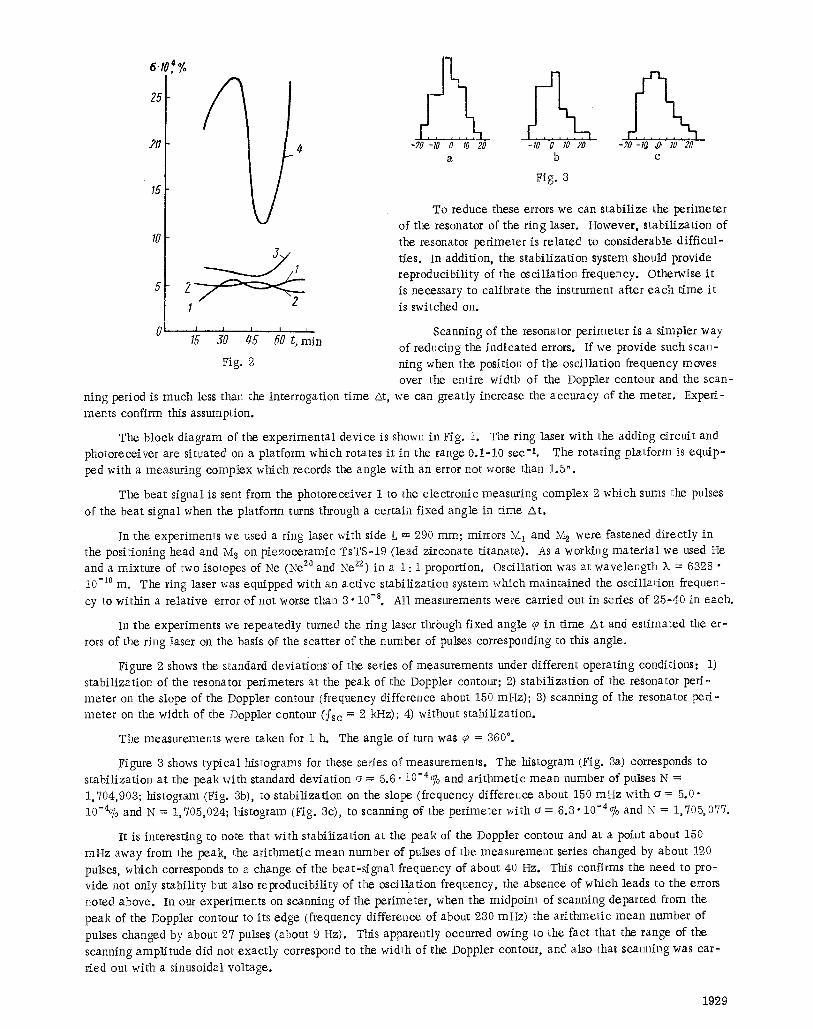
Figure 2 shows the standard deviations of the series of measurements under different operat ing conditions: 1) s tabi l izat ion of the resonator perimeters at the peak of the Doppler contour; 2) s tabi l izat ion of the resonator per i - meter on the slope of the Doppler contour (frequency difference about 150 mHz); 3) scanning of the resonator per i -
meter on the width of the Doppler contour (fse = 2 kHz); 4) without s tabi l izat ion.
The measurements were taken for 1 h. The angle of turn was ~a = 360%
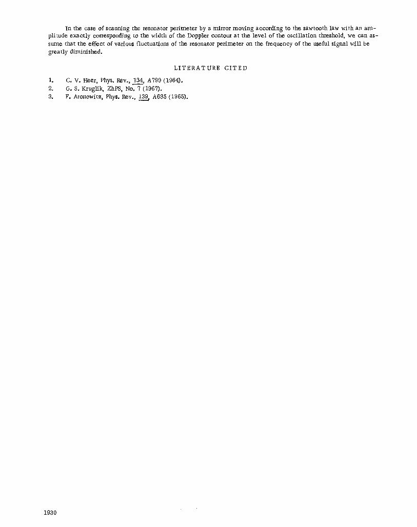
Figure 3 shows typ ica l histograms for these series of measurements . The histogram (Fig. 3a) corresponds to s tabi l iza t ion at the peak with standard deviat ion o = 5.6" 10-4% and a r i thmet ic mean number of pulses N = 1,704,903; histogram (Fig. 3b), to s tabi l iza t ion on the slope (frequency difference about 150 mHz with a = 5.0" 10-4O7o and N = 1,705,024; histogram (Fig. 3c), to scanning of the per imeter with ~ = 6.3" 10-4% and N = 1,705,077.
It is interesting to note that with s tabi l iza t ion at the peak of the Doppler contour and at a point about 150
rnHz away from the peak, the a r i thmet ic mean number of pulses of the measurement series changed by about 120 pulses, which corresponds to a change of the bea t - s igna l frequency of about 40 Hz. This confirms the need to pro- vide not only s tabi l i ty but also reproducibi l i ty of the osci l lat ion frequency, the absence of which leads to the errors noted above. In our experiments on scanning of the per imeter , when the midpoint of scanning departed from the
peak of the Doppler contour to its edge (frequency difference of about 230 mHz) the a r i thmet ic mean number of
pulses changed by about 27 pulses (about 9 Hz). This apparent ly occurred owing to the fact that the range of the
scanning ampl i tude did not exac t ly correspond to the width of the Doppler contour, and also that scanning was ca r -
fled out with a sinusoidal voltage.
1929
In the case of scanning the resonator per imeter by a mirror moving according to the sawtooth law with an a m - plitude exact ly corresponding to the width of the Doppler contour at the level of the osci l lat ion threshold, we can as- sume that the effect of various fluctuations of the resonator perimeter on the frequency of the useful signal wil l be greatly diminished.
1o
2. 3.
LITERATURE CITED
C. V. Heer, Phys. Rev., 134, A799 (1964). G. S. Kruglik, ZhPS, No. 7 (1967). F. Aronowitz, Phys. Rev., ~ A635 (1965).
1930