method of forming routing data
TRANSCRIPT
(12) United States Patent Hummel
US006333918B1
(10) Patent N0.: (45) Date of Patent:
US 6,333,918 B1 Dec. 25, 2001
(54) METHOD OF FORMING ROUTING DATA
(75) Inventor: Heinrich Hummel, Guending (DE)
(73) Assignee: Siemens Aktiengesellschaft, Munich (DE)
( * ) Notice: Subject to any disclaimer, the term of this patent is extended or adjusted under 35 U.S.C. 154(b) by 0 days.
(21) Appl. No.: 09/091,636
(22) PCT Filed: Dec. 4, 1996
(86) PCT No.: PCT/EP96/05423
§ 371 Date: Apr. 8, 1999
§ 102(e) Date: Apr. 8, 1999
(87) PCT Pub. No.: WO97/23978
PCT Pub. Date: Jul. 3, 1997
(30) Foreign Application Priority Data Dec. 21, 1995 (EP) ............................................ .. 95 120 259
(51) Int. Cl.7 ........................... .. H04L 12/24; H04L 12/66
(52) us. Cl. ........................ .. 370/238; 370/255; 370/400; 709/238
(58) Field of Search ................................... .. 370/217, 218,
370/225, 228, 229, 235, 238, 254, 255, 256, 389, 395, 396, 397, 400, 401, 709/238,
239, 240, 241, 242, 243
(56) References Cited
U.S. PATENT DOCUMENTS
5,144,619 9/1992 Munter .............................. .. 370/60.1
5,265,092 * 11/1993 Soloway et al. 370/60 5,408,469 4/1995 Opher ........... .. 370/60.1 5,488,608 * 1/1996 Flammer, III .. . 370/85.13 5,491,690 * 2/1996 Alfonsi et al. . 370/60 5,495,479 * 2/1996 Galaand et al. 370/60 5,541,915 7/1996 Storm ........... .. 370/60.1
5,629,930 5/1997 Beshai et al. .. .. 370/39.6 5,781,529 * 7/1998 Liang et a1. .... .. 370/218 5,781,537 * 7/1998 Ramaswami et a1. 370/254 5,831,982 * 11/1998 Hummel ............................. .. 370/396
8.1
OTHER PUBLICATIONS
Computer Networks and ISDN Systems, vol. 12, No. 1, (1986) Amsterdam, Netherlands, A.E. BaratZ et al, Estab lishing Virtual Circuits in Large Computer Networks, pp. 27—37. Computer Communication Review, vol. 25, No. 2, Apr. 1995, WC. Lee, Topology Aggregation for Hierarchical Routing in ATM Networks, pp. 82—92. IEEE Journal on Selected Areas in Communications, vol. 7, No. 8, Oct. 1989, New York, V.R. Saksena, Topological Analysis of Packet Networks, pp. 1243—1252. Proceedings of Infocom ’95, Conference on Computer Com munications, 14th Annual Joint Conference of the IEEE Computer & Communications Societies, Boston, vol. 3, Apr. 1995, GM. Huang et al, ANew HAD Algorithm for Optimal routing of Hierarchically Structured Data Networks, pp. 594—601. ATM Forum 94—0471R14, Appendix H: Route Generation Algorithm, A Sample Algorithm for Route Generation, pp. 314—321.
* cited by examiner
Primary Examiner—Alpus H. Hsu (74) Attorney, Agent, or Firm—Schiff Hardin & Waite
(57) ABSTRACT
Switching nodes of a communications network are assigned subnetworks and are interconnected to one another in any desired fashion. Stored in a source switching node is at least topology information on the node’s own subnetwork and on the interconnection of the subnetworks. In addition, the source switching node is provided with the communications conditions which are required for the communications link to be set up. By reference to the topology information, a subset of switching nodes and connecting lines which sat is?es the communications conditions is selected and a route to the destination switching node is determined. Included in this process is a route which, in the direction from the source switching node to the destination switching node, leaves at least one subnetwork once and returns to the subnetwork again in the further course of the route. The routing infor mation is then formed from the route which has been determined.
10 Claims, 11 Drawing Sheets
U.S. Patent Dec. 25,2001 Sheet 1 0f 11 US 6,333,918 B1
25: 8:2
F 01
U.S. Patent Dec. 25,2001 Sheet 2 0f 11 US 6,333,918 B1
m8: 5:2 5
U.S. Patent Dec. 25,2001 Sheet 3 0f 11 US 6,333,918 B1
5
25: 5:2 -:$QH@.< 2
ma

U.S. Patent Dec. 25,2001 Sheet 4 0f 11 US 6,333,918 B1
U.S. Patent Dec. 25,2001 Sheet 5 0f 11 US 6,333,918 B1
Dest=Stuttqart 2
U.S. Patent Dec. 25,2001 Sheet 6 0f 11 US 6,333,918 B1
l ._-.-L_-___-__________J ggS
mode:
16-2 ; :9
20
g. £ 13 14
C
14
F \Y
lgei?sie L.
nk : -2; 4; 45; 2-8
10; 6-15 7-8 7-10
.51, .1135 I 11
U.S. Patent Dec. 25,2001 Sheet 7 0f 11 US 6,333,918 B1
U.S. Patent Dec. 25,2001 Sheet 8 0f 11 US 6,333,918 B1
U.S. Patent Dec. 25,2001 Sheet 9 0f 11 US 6,333,918 B1
Y h 0911355 /Spuke N B03 exception AH P
Source=Atlanta L..________.-__-_-______-_.._._____j
Dest=Las Vegas

U.S. Patent Dec. 25,2001 Sheet 11 0f 11 US 6,333,918 B1
—__——_m————__n-_.-__
Desl=Stuttgart 2
US 6,333,918 B1 1
METHOD OF FORMING ROUTING DATA
BACKGROUND OF THE INVENTION
When links are routed in communications networks such as narroWband or ATM networks (AT M=Asynchronous Transfer Mode), for example, there are basically tWo alter native approaches, namely the “hop-by-hop routing method”, in Which each transit node itself decides hoW to the forWard the connection set-up request, and source routing in Which the source node S (to Which the subscriber initiating the connection request is connected) adds a route description to the connection set-up message, Which description has to be folloWed by the transit nodes in order to arrive at the destination node D (to Which the requested terminating subscriber is connected). This route description information is also referred to as routing information or source routing information or, speci?cally in the case of ATM-PNNI netWorks, is referred to as DTL stack (=stack of Designated Transit List information elements).
Said ATM communications netWorks can be organiZed into numerous subnetWorks (“peer groups”), comprising physical sWitching nodes and physical connecting lines (“physical links”). According to the PNNI protocol, the nodes of a (hierarchically loWest) peer group determine from among them a so-called representative node (“peer group leader”) Which represents the entire peer group in the form of a single, logical, model-like node (referred to as “logical group node” or else “parent node”) in a peer group Which is of a hierarchically higher level. A hierarchically higher peer group is formed, comprising
a plurality of such parent nodes and the connecting lines Which interconnect these in a model-like fashion, in Which case a model-like connecting line (also referred to as “higher-level logical link”) betWeen tWo such parent nodes thus represents all those physical connecting lines Which connect in each case tWo physical boundary nodes from the hierarchy region of the tWo adjacent parent nodes and, in doing so, have assigned to them, thanks to administrative speci?cations and an agreement algorithm, the same code in each case, referred to as aggregation token.
The hierarchy can continue recursively in further hierar chy levels: a peer group leader selection can also take place again in the hierarchically higher peer group. The peer group leader Which is selected here represents again the entire hierarchy region established under it in a peer group Which is hierarchically at the next highest level, as if this hierarchy region Were a single node. In this peer group there are also logical, model-like connecting lines Which are formed repeatedly, as described above.
Ahierarchical model-like netWork in accordance With the PNNI protocol (for illustration purposes: 3-dimensional grid) is completed by adding further, purely logical connect ing lines, the so-called “uplinks” Which each connect, in accordance With the PNNI protocol, tWo nodes to one another (physically—if the node at the loWer end of the uplink is a physical node—or logically) from peer groups Which are at hierarchically different levels.
Thus, an uplink (also referred to as “initial uplink”) leads from the boundary node of a hierarchically loWest peer group, Which node is connected to a boundary node in an adjacent peer group, to a representative node, the so-called “upnode”, i.e. to that representative node “ancestor node” (i.e. parent node, grandparent node or great . . . grandparent node) of the adjacent boundary node Which is a directly neighboring node of precisely one speci?c ancestor node of the boundary node on this side in a common peer group of
10
15
25
35
45
55
65
2 a hierarchically higher level. Such an (initial) uplink results in all the ancestor nodes (of the boundary node on this side) Which hoWever each belong to a hierarchically loWer peer group than the aforesaid common hierarchically higher peer group, also each contribute an uplink (also referred to as “induced uplink”) to the aforesaid upnode [lacuna] the hierarchy pattern. The hierarchical structure, Which is ultimately based on
corresponding con?guration data of the individual nodes, can be handled very ?exibly here. In particular, the indi vidual nodes of a great . . . grandparent peer group can have
different numbers of subhierarchy levels together With the relevant peer groups. The exchange, in accordance With PNNI protocol, of data
packets, “hello packets” and PNNI topology status data packets (“PNNI topology state packets”—PTSPs) via so-called routing control channels ensures that each physical sWitching node of a hierarchically loWest peer group acquires the same knoWledge of the topology of this group and of all the peer groups, including all the uplinks, Which are located at a hierarchically higher level than it in the hierarchy, and also the same knoWledge of the usage factor of all the nodes and connecting lines contained in it as Well as the same knoWledge of its properties (accessibility, capabilities, features, costs). The knoWledge of the topology Which is acquired can be
stored in a node in the form of a graph G1. In it, the respective current sWitching node (Which has produced this graph G1 for itself) is not marked in particular as the source node S.
If a terminal Which is connected to the source node then requests to be connected to the terminal of a speci?c destination address, the data in the graph G1 Which are exchanged per PNNI routing protocol make it possible to determine that destination node D Which indicates the acces sibility of the destination terminal and at the same time belongs to the hierarchically loWest possible peer group. On the basis of the graph G1 it is possible to determine, in terms of a suitable minimiZation criterion, the best route from the starting node S to the destination node D. The ATM Forum Technical Committee Private NetWork
Node Interface (PNNI) in the speci?cation, version 1.0, Annex H does not, hoWever, provide the possibility of also including in the route search advantageous bypasses via one or more peer groups With a return to the peer group Which has already been passed through, and as a result it is in the meantime not possible to ful?ll a sWitching request appro priately.
These problems also occur in other communications netWorks, for example narroWband netWorks With source routing for implementing a PSTN (Public SWitched Tele phone NetWork). The topology information is evaluated only to the extent that routes are determined With the avoidance of bypasses.
SUMMARY OF THE INVENTION
The object of the method according to the invention consists in determining a route, While taking into account the topology information and the communications conditions relating to the nodes and connecting lines, and converting the route into routing information in such a Way that the largest possible variety of routes can be taken into account. The sWitching nodes are assigned to subnetWorks and
interconnected to one another as desired. The subnetWorks here can be individual local communications netWorks of different service providers or groups of sWitching nodes of
US 6,333,918 B1 3
a superordinate communications network. In a source switching node there is topology information available on the node’s oWn subnetWork and on the inter-connection With the subnetWorks Which are stored in the node or in a routing server. In addition, the communications conditions Which are required for the communications connection to be set up are available to the source sWitching node. By referring to the topology information, a subset of
sWitching nodes and connecting lines Which satis?es the communications conditions is selected and a route to the destination sWitching node is determined. Included in this process is a route Which, in the direction from the source sWitching node to the destination sWitching node, leaves at least one subnetWork once and returns to said subnetWork in the further course of the route. The routing information is then formed from the route Which is determined. The formation of the routing information is carried out either in the sWitching node itself or in external devices, for example routing servers, Which can be connected to the sWitching node. The method according to the invention can be implemented, for example, in the Xpress sWitching nodes from Siemens AG. On the basis of a topology graph Which is based, for
example, on the topology information acquired by the PNNI routing protocol, a possibly reduced topology graph is derived such that the remaining nodes and edges ful?ll, inter alia, the conditions of the current connection request. It is ensured that the topology graph is not reduced too much so that bypasses are made possible in Which it Would be possible to pass through nodes and edges Which belong to a higher hierarchical level than the destination node D. A routing algorithm Which is carried out on this basis
results in a route Which makes bypasses via other subnetWorks, and it is thus in terms of the minimiZation criterion applied the instantaneously best route—for instance because no routes Without bypasses are possible oWing to the instantaneous netWork usage factor, or if they are possible they are less favorable. The latter is probable in particular if the netWorks/subnetWorks (peer groups) are formed on the basis of organiZational vieW-points (oWners, departments, . . . ), but geographically cover the same area.
A communications connection Which is set up according to this routing information Will certainly also comprise bypasses Which Would be avoidable if a direct route Were possible Within a subnetWork While complying With the communications conditions. HoWever, as a result of the method according to the invention, blocking Within the subnetWork is avoided. The number of permitted routes is substantially expanded and the service providers of the communications netWork are presented With expanded con ?guration possibilities by virtue of the use of additional subnetWorks for a connection set-up.
The advantageous con?guration of the invention includes the voluntary limitation of the potential degree of bypasses. Here, the highest peer groups are advantageously removed, as it Were voluntarily, from the topology graph. This aspect is important if private and public netWorks form a common hierarchy and, for example for reasons of cost, the bypass via public netWorks is to be prevented.
The sWitching nodes or subnetWorks are advantageously implemented as a narroWband netWork or ATM netWork. The method according to the invention can, hoWever, also be applied to hybrid forms of communications netWorks, With the result that only parts of the communications netWork are implemented in this Way. A particularly simple Way of implementing the method
according to the invention is obtained if at least some of the
10
15
25
35
45
55
65
4 sWitching nodes operate according to the principles of the Private Network Node Protocol (PNNI). The sWitching nodes of a subnetWork are represented here by a complex sWitching node in the topology information. The hierarchi cal structuring of parts of the communications netWork is made easier in this Way. In addition, a reduction in expen diture is obtained in terms of the determination of routes, Which is advantageously carried out according to the Dijk stra algorithm.
According to a further advantageous re?nement of the method according to the invention, the connecting lines betWeen tWo sWitching nodes are handled separately in both traffic directions. This is effected in that, for example, each undirected edge is replaced by in each case tWo oppositely directed edges, each individually directed edge being assigned both forWard and rearWard attributes.
In this Way, the one directed edge can remain in the topology graph While the oppositely directed edge is removed if the communications requirements are such that the connection set-up is made possible only in the one direction. Here, an oppositely directed doWnlink is incorpo rated into the topology graph for each uplink. On the other hand, the Dijkstra routing algorithm ensures that only monotonously directed edge sequences result as routes.
Thus, a connection line can be passed through in one direction during a connection set-up even if speci?c com munications conditions are not ful?lled in the other direc tion. When the communications conditions are not ful?lled by
a sWitching node or a connecting line, making it impossible, for example, to set up a connection via the previously determined route or to clear a connection, the respective sWitching node or the respective connecting line is signalled to the source sWitching node or an initial sWitching node of the corresponding subnetWork, in response to Which the latter can perform a neW route determining process.
During the route determining process, according to devel opments of the invention, the routes With the shortest connecting lines or the loWest number of sWitching nodes to be passed through are selected. In this process, if appropriate, geographic information on the sWitching nodes may be accessed. If the topology information advanta geously contains cost-speci?c information, the route With the loWest costs is selected. During the selection of the most favorable route, the folloWing minimiZation criteria may therefore be taken into account individually or in a com bined fashion: Number of nodes to be passed through, The sum of the distances betWeen the nodes to be passed
through, The delay time of the transmission (cell transfer delay), Variation in the delay time of a transmission (cell delay
variation), Transmission costs.
BRIEF DESCRIPTION OF THE DRAWINGS
The features of the present invention Which are believed to be novel, are set forth With particularity in the appended claims. The invention, together With further objects and advantages, may best be understood by reference to the folloWing description taken in conjunction With the accom panying draWings, in the several Figures of Which like reference numerals identify like elements, and in Which: 1st Exemplary Embodiment
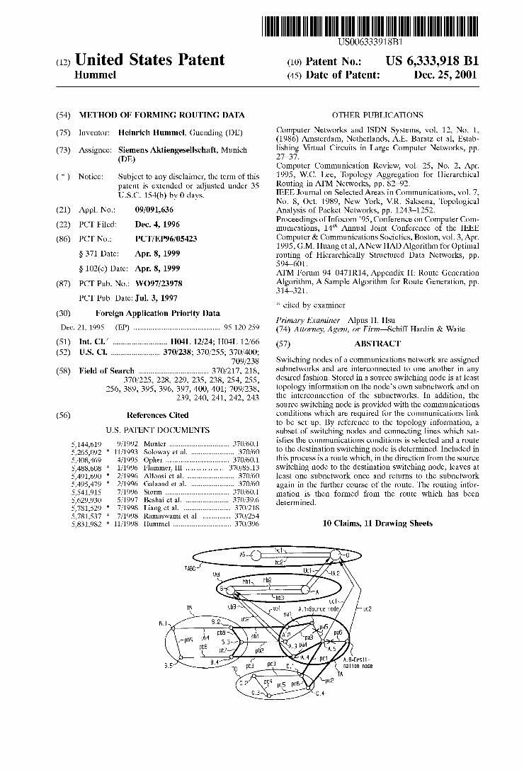
FIG. 1 shoWs an ATM communications netWork from the point of vieW of the source sWitching node A.1,

US 6,333,918 B1 5
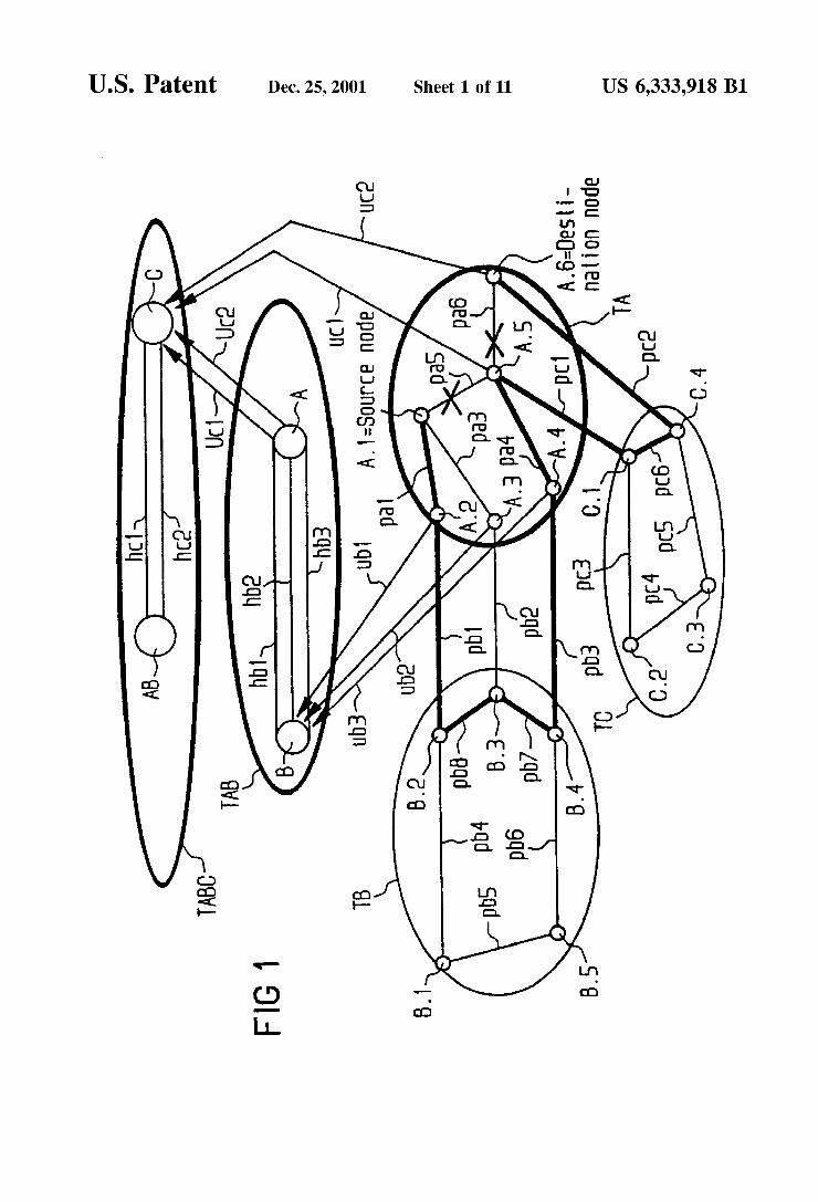
FIG. 2 shows an ATM communications network from the point of view of the transit switching node B.2 and
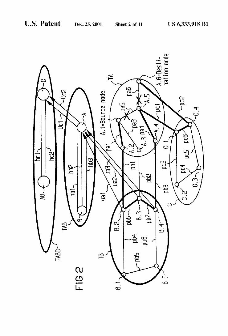
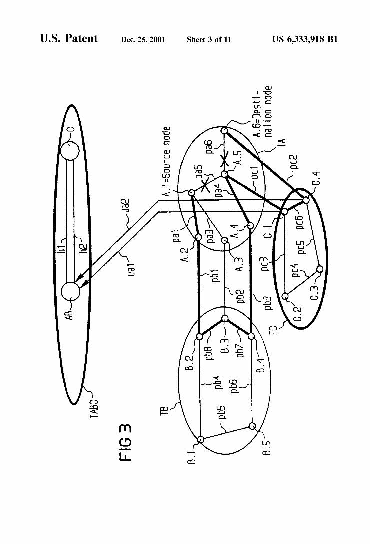
FIG. 3 shows an ATM communications network from the point of view of the further transit switching node C.1. 2nd Exemplary Embodiment
FIG. 4 shows a network topology of an ATM communi cations network,
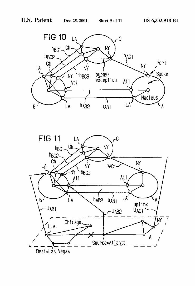
FIG. 10 shows network topology represented by complex nodes,
FIG. 11 shows a topology graph for a node of subnetwork A,
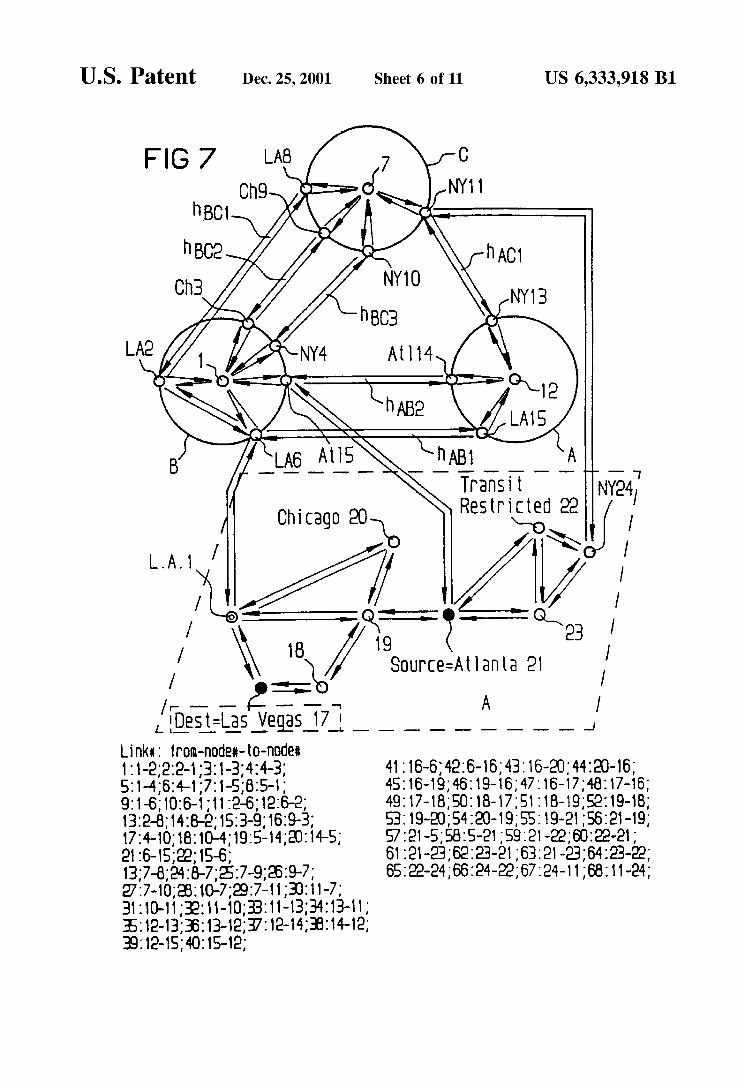
FIG. 7 shows a topology graph for a node of subnetwork A with independent traffic directions,
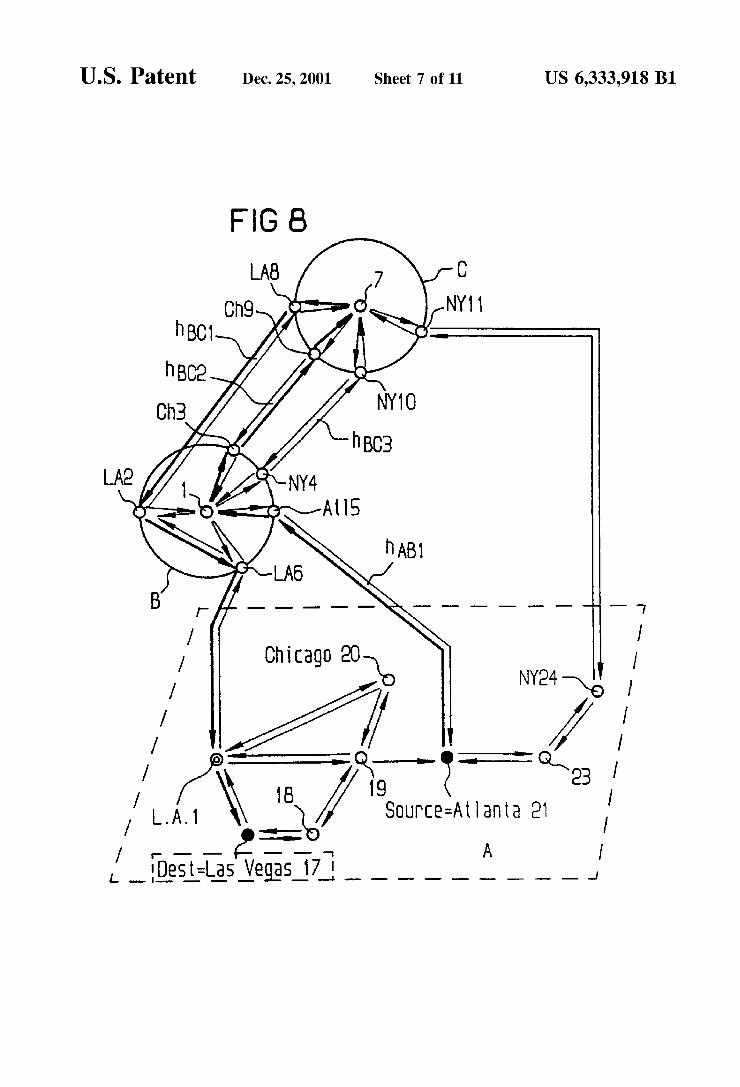
FIG. 8 shows a route which has been determined. 3rd Exemplary Embodiment
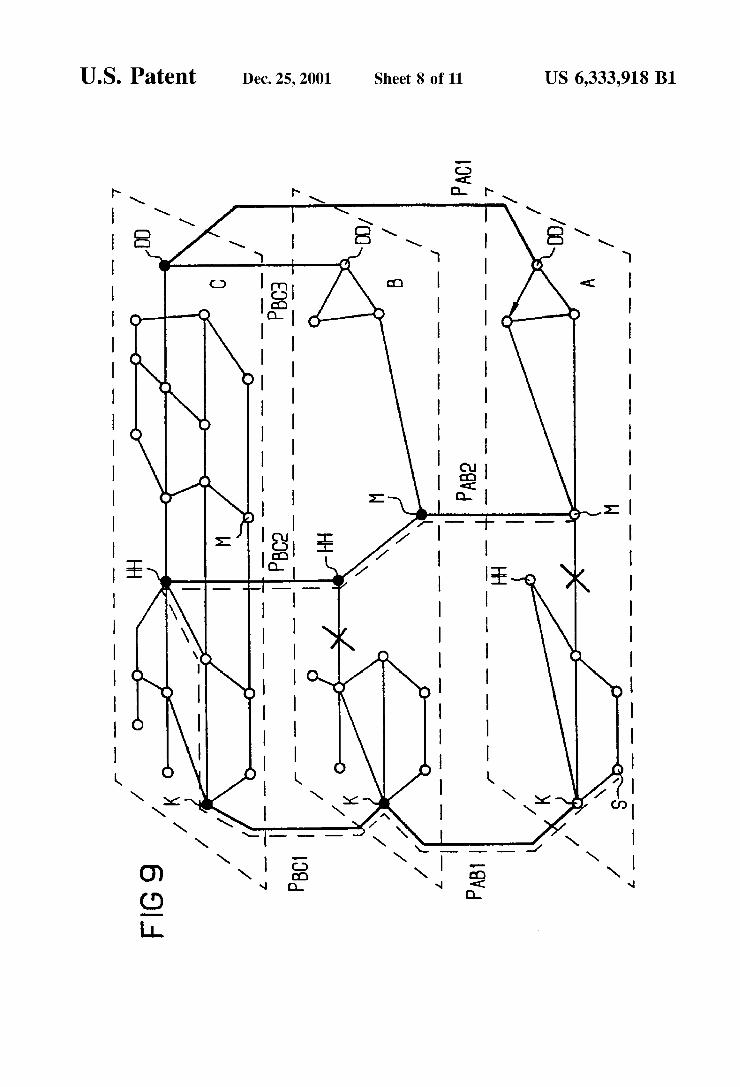
FIG. 9 shows a network topology of a narrowband com munications network,
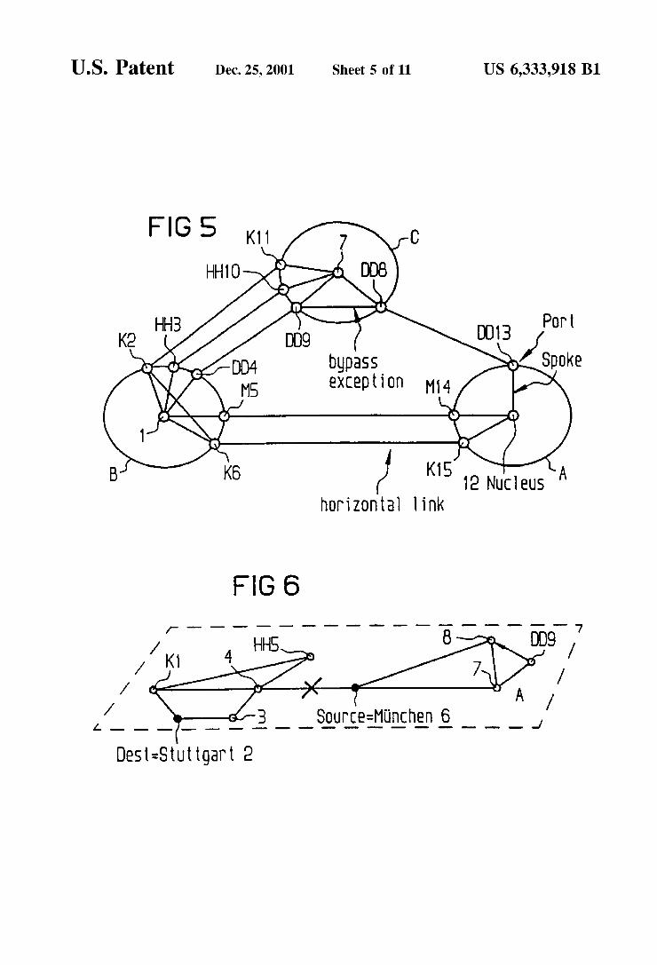
FIG. 5 shows network topology represented by complex nodes,
FIG. 6 shows a topology graph for a node of subnetwork A,
FIG. 12 shows a topology graph for a node of subnetwork A with independent traffic directions,
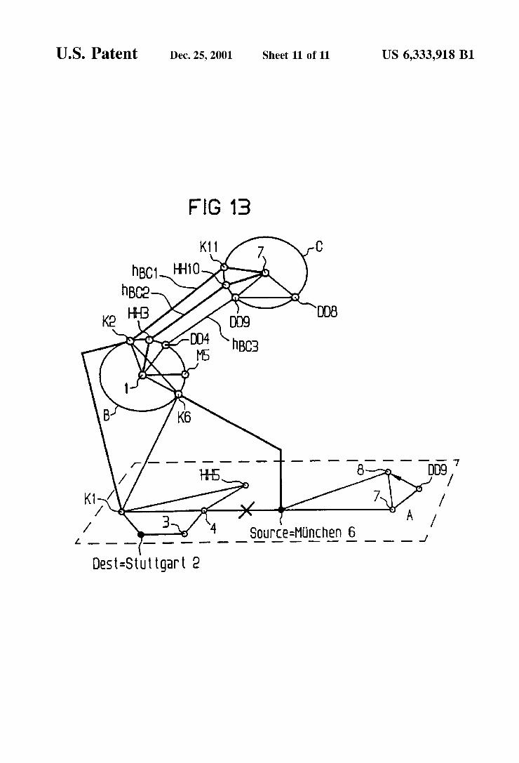
FIG. 13 shows a route which has been determined.
DESCRIPTION OF THE PREFERRED EMBODIMENTS
1st Exemplary Embodiment (PNNI Network with Only Simple Nodes)
In a ?rst exemplary embodiment (FIGS. 1 to 3), a graph G2 is determined which, with reference to the scenario of an ATM communications network described at the beginning, is derived from the aforesaid graph G1 by removing from graph G1 all those nodes and connecting lines which do not comply with the communications conditions.
Subsequently, an optimum connection path is determined such that bypasses via hierarchically higher peer groups with subsequent return to hierarchically lower peer groups which have already been passed through are also taken into account. Here, the exit nodes and re-entry nodes for one and the same peer group are different; otherwise such a detour would constitute an extremely unnecessary loop and not an optimum connection path.
Even if the following exemplary embodiment concen trates on detour-like routes, it must not be forgotten that, for normal cases in which a best, detourless route is available, the method according to the invention also ?nds said route and equally correctly forms the corresponding routing infor mation for it.
The resulting optimum route can in principle contain any desired number of transitions from a hierarchically higher peer group to a hierarchically lower peer group and, vice versa, from a hierarchically lower peer group to a hierar chically higher peer group, in which case at each individual transition in principle any desired number, i.e. Zero, one, two, . . . or n<=102 hierarchy levels may be skipped.
In accordance with the PNNI protocol, the connection set-up message is also given the routing information as a consequence of information elements, so-called “Desig nated Transit List information elements (DTLs)”, a preced ing information element (repeat indicator) indicating the stack-like handling of these DTLs (push and pop operations). Here, each information element DTL contains the description of precisely one route through precisely one hierarchical peer group in the form of one or more node links
10
15
25
35
45
55
65
6 (also referred to as edge later) pair speci?cations and a pointer which points to one of these node link pairs.
The route which is described from the uppermost infor mation element DTL of the push-down storage starts here with the source node S and contains only speci?cations relating to nodes and connecting lines in the hierarchically lowest peer group and ends, if appropriate, with the speci ?cation of an uplink which leads to an upnode at which the route continues, speci?cally in the way described in the next lowest stacked DTL.
Each next lowest DTL in the push-down storage contains speci?cations for, in each case, one route through the hierarchically next highest peer group, said speci?cation starting with the speci?cation of the relevant ancestor node of the source node, possibly followed by further node and connecting line speci?cations from the same peer group and a possible uplink speci?cation as termination. The lowest DTL in the stack contains speci?cations relating to a route through the hierarchically highest peer group required, start ing with the speci?cation of the relevant ancestor node of the source node and ending at a node in whose hierarchy region the destination node with the connected destination terminal is located. The described design of the DTL push-down storage in
accordance with the PNNI protocol initially gives the impression that it would be impossible to take into account routes which comprise any desired sequences of hierarchi cally higher and hierarchically lower nodes, and that it is actually indicated to design the algorithm for searching an optimum connecting path in such a way that routes which such sequences (that is to say with bypasses via hierarchi cally higher peer groups) are excluded from the outset, as is the case in the speci?cations of the PNNI protocol, version 1.0, Annex H. However, the method according to the invention solves
the problem of describing a route containing bypasses in such a form that the rules of the PNNI protocol are satis?ed.
It is characteristic of the solution of the ?rst exemplary embodiment that from a prescribed sequence of hierarchi cally higher and hierarchically lower nodes, in which sequence uplinks would certainly also have to be passed through in the downward direction, an equivalent sequence of nodes and connecting lines is derived which never runs in a descending fashion in terms of the hierarchy levels of these nodes and in which therefore uplinks never have to be passed through in the downward direction. As an attribute of what is achieved in this way, one and the same hierarchically higher (logical) node can occur repeatedly in the sequence (loops) but, owing to the connecting lines which are speci?ed, it is clearly ensured that the exit and re-entry boundary nodes in the relevant child peer groups are always different, which ultimately means that one and the same physical node is never passed through more often than once.
Below, the determination of the best route in a switching node which determines the route and the routing information is explained for the ?rst exemplary embodiment: A graph G3 is derived from the abovementioned graph G2 by removing all the ancestor nodes of the source node S, likewise all the (horiZontal) connecting lines which lead away from said nodes and which would lead from precisely these ancestor nodes to their adjacent nodes in the corre sponding hierarchically higher peer groups, and all the induced uplinks leading away from these ancestor nodes in the upward direction.
In accordance with the PNNI protocol, a best route is determined in a known manner, for example using the
US 6,333,918 B1 7
Dijkstra routing algorithm, from the source node S to the destination node D based on the graph G3, the uplinks remaining in the graph G3 having to be treated no differently than all the other (horizontal) connecting lines.
The sequence F1 in general notation:
node-n(=D), link-n-1, . . . , node-i+1, link-i, . .
node-1(=S) is obtained as best route.
It is in the nature of the Dijkstra routing algorithm that the respective best route is determined not only to a single, speci?c destination node D, but rather to all nodes of the netWork, and afterWards the route of interest, for eXample to the destination node D, is picked up. By means of the Dijkstra algorithm, this route is initially determined here in the form of the sequence F1. Then, the sequence is turned about and the sequence F2:
node-1(=S), link-1, . . . , link-i, node-i+1, . . . , link-n-1,
node-n(=D) is formed.
The physical source node-1=S is naturally of the hierar chically loWest level. All the other nodes must, according to the invention, be in order, as often as desired, hierarchically higher or hierarchically loWer physical or logical nodes. In particular, the destination node node-n=D must not neces sarily be the hierarchically highest of the nodes occurring in the sequence. A link, link-i, proves to be horiZontal if node-i and
node-i+1 are assigned to the same hierarchy level, that is to say belong to the same hierarchical peer group. Alink, link-i, proves to be an uplink in the upWard direction (or doWnWard direction) if the hierarchy level from node node-i is smaller (or larger) than the hierarchy level from node node-i+1.
According to the invention, from the sequence F2 a sequence F3 is derived, in Which the nodes in the prescribed sequence never descend in terms of their hierarchy level. SWitching nodes and links from F2 are, if appropriate, replaced or canceled out by others here. For this purpose, an auXiliary variable, referred to here as a CurrentNodeLevel, Which is initialiZed With the hierarchy level of the node node-1=S, is used, together With a second Boolean auXiliary variable, referred to here as BeloWHighestReachedLevel, Which is initialiZed With FALSE. In an iteration loop, all the components of the sequence F2 (the links and the nodes) are run through, starting at source node node-1=S, and in the meantime replacements or cancellations are carried out— see the folloWing algorithm:
. , link-1,
BeloWHighestReachedLevel := FALSE;
currentinode := node-1;//i.e. = Source Node S
CurrentNodeLevel := Hierarchy level of the currentinode;
for i:=1 step 1 to n—1 do if hierarchy level of the node-i+1 is loWer than
CurrentNodeLevel then if BeloWHighestReachedLevel = FALSE then
determine that ancestor node of node-i+1 Whose hierarchy level is equal to the CurrentNodeLevel. Replace link-i, Which is an uplink passed through in the doWnWard direction, With the associated horiZontal link (With the same aggregation token). HoW to do this: see Subtask-1 after this algorithm. Replace node i+1 With the ancestor node Which has been determined. BeloWHighestReachedLevel:= TRUE;
1O
15
25
35
45
5
a O
8 else
cancel link-i and node-i+1 from the sequence. end
else if BeloWHighestReachedLevel = TRUE then
replace link-i With that assigned (induced) uplink or else horiZontal link Which starts from the level given by CurrentNodeLevel and leads to the node i+1. HoW to do this: See Subtask-2 after this algorithm. Node-i+1 is retained unchanged in the sequence. BeloWHighestReachedLevel := FALSE;
else retain link-i and note-i+1 unchanged in the sequence.
end
CurrentNodeLevel := Level of node-i+1; end Next i; Subtask-1:
Determine the associated horiZontal link in the hierarchi cally higher peer group for a prescribed uplink: The graph G1 has m links (horiZontal links and uplinks
taken together). The number k from the set 1,2, . . . , m
represents a pointer to the interesting information relating precisely to one link (for eXample its identity speci?cations). In particular, assume that there is a table RelationTbl With m elements. The elements represent the assignment chain from the initial uplink to the possibly induced uplink, to the uplink Which is possibly derived therefrom again, etc., to the horiZontal link induced therefrom in a hierarchically higher peer group: RelationTbl? 1:I I= 1'2; // if there is no value k of 1 to m With
RelationTbl (k):=j1, 1 is the initial uplink RelationTblDq_1] := j q;
RelationTbl?kl] i= 1}; RelationTblDS] I= 0;
Which means:
link- j1 is uplink and induces link- j2 link- j,_1 is uplink and induces link- j, link- jS_1 is uplink and induces link- jS link- jS is a horiZontal link. // If there is no value jS_1 of 1 to m With RelationTbl
(jS_1):=jS, but there is an entry RelationTblLjS] := 0, jS is a horiZontal link in a hierarchically loWest peer group. Assuming that the link-i to be replaced corresponds to
j q_1, the table RelationTbl is run through until RelationTbl D5] := 0 is arrived at. jS de?nes the horiZontal link to be used. Subtask-2:
For all the m links of the graph G1 there is a table of the type: LinkLevelTbl[k] = loWest hierarchy level of the tWo bound ary nodes of the link k; for all k=1, . . . m. link-i is designated by j q_1. The table RelationTbl is run through starting from RelationTblDq_1] in order to pass from one link to the neXt link, and, in the process, CurrentNodeLevel is continuously compared With the entries in LinkLevelTbl. Assuming that the value of CurrentNodeLevel is equal to the value of LinkLevelTblLj,_1], j,_1 identi?es the searched-for link Which is to replace link-i. From the sequence F3, it Will be assumed that a sequence
F4 is formed, for eXample as folloWs: for i:=1 step 1 to n-1 do if link-i=uplink then
US 6,333,918 B1
insert after link-i that ancestor node from source node S Which is of the same hierarchy level as node-i+1. In turn, insert after that horizontal link H Which is assigned to the link-i by virtue of the identical aggre gation token (the RelationTbl is run through starting at j1=link-i and H=j5 is found).
end next i; From F4, a sequence of DTLs is formed by breaking up
the sequence F3 after each uplink, and from each subse quence Which is generated in this Way a DTL information element With PNNI protocol-compatible syntax is formed, Which completely describes the task according to the inven tion for the source node S.
According to the invention, a loop can be integrated (in the terms of the method according to the invention this is a bypass via one or more peer groups With return to a peer group Which has already been passed through at a re-entry node Which has not yet been passed through) even When the information elements of the routing information are ful?lled again When the connection set-up message arrives in a physical sWitching node (transit node) to be passed through. This is clari?ed beloW With reference to the arrival of a connection set-up message in the ?rst physical sWitching node of a hierarchically loWest peer group:
If the peer group Which is the hierarchically loWest at a given moment is exited When a connection set-up message is being passed on, the relevant uppermost DTL in the stack must have previously been removed. If even a certain hierarchy range is exited, all those uppermost information elements DTL in the stack Which contain routing sections through the respective peer groups of the hierarchy region to be exited must previously have been removed. If a peer group Which is hierarchically the loWest is re-entered When a connection set-up message is being passed on, neW routing sections must be determined and neW relevant DTLs must be formed. The pointers in the individual DTLs must alWays have been set and/or moved forWard in such a Way that When a connection set-up message is received the pointers of all the received DTLs each point to a node link pair Which contains either the received physical node Which is the loWest in the hierarchy or else one of its ancestor nodes.
The boundary node (S‘) determines, as entry node into a further peer group, a neW best route section as far as a destination node D‘. The destination node D‘ is to be taken from the node link pair Which folloWs the node link pair in the DTL Which is uppermost in the stack of the received DTLs and to Which the relevant pointer points.
If this is not possible because the pointer is already pointing to the last node link pair, the same applies With respect to the next loWest DTL in the stack, and so on. It is Within the spirit of the invention that the PNNI protocol prescribes that the received link speci?cation, namely hoW a node D‘ is arrived at, must also be complied With com pletely. Any attempt, for example to get there in a better Way, could certainly produce a better route section, but at the same time could also lead to the hierarchy region repre sented by the destination node D‘ not being entered at the expected boundary node, from Where the continuation of the connection set-up could ?nish up in a dead end. That is to say in addition to D‘ the horiZontal link Link-to-D‘ is also determined. Link-to-D‘ is taken from the node link pair Which belongs to that DTL in Which D‘ is located and to Which the relevant pointer points during the reception of the DTL.
The boundary node S‘ Which considers that it is only a transit node for the present connection set-up request and
10
15
25
35
45
55
65
10 that the received DTL push-doWn storage is incomplete, therefore forms, on the basis of its oWn graph G1, a possibly reduced graph G1‘, as folloWs:
All the nodes—together With the adjacent links—With a hierarchy level Which is greater than or equal to the hierar chy level of the node D‘ are removed from the graph G1, but not D‘ itself and also not those uplinks for Which D‘ is an upnode and are at the same time assigned to the Link-to-D‘. That is to say for all uplinks Which have D‘ as an upnode the folloWing test is made: As in Subtask-1, a J q_1 can be assigned to an uplink. The
table RelationTbl Will be run through starting from RelationTbl? q_1] until an entry RelationTblDS] :=0 is arrived at. If js corresponds to Link-to-D‘, the uplink can remain in the graph G1‘. OtherWise, it is removed. The graphs G2‘ and G3‘ are formed on the basis of G1‘, by complete analogy With the Way that the source node S formed the graphs G2‘ and G3‘, and a DTL stack is determined as described above, S‘ performing the function of S and D‘ performing the function of D (see description above).
All the DTLs, With the exception of the last-but-one (Which contains D‘) are transferred from the resulting DTL push-doWn storage and the DTL push-doWn storage to be passed on is thus completed.
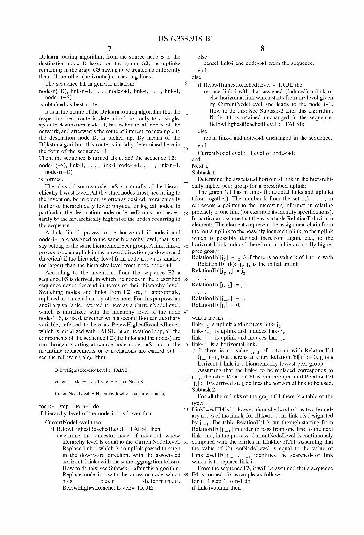
The formation of the routing information in the sWitching node of an illustrated ATM communications netWork Will be explained With reference to FIGS. 1 to 3. Here, FIGS. 1 to 3 shoW one and the same ATM communications netWork for a routing search and the formation of routing information, but vieWed from different sWitching nodes.
The hierarchy structure of the ATM communications netWork shoWs three subnetWorks TA, TB, TC by Way of example. The ?rst subnetWork TA comprises the physical nodes A.1 . . . 6. For the connection set-up in question, the
node A1 is the source sWitching node and the node A6 is the destination sWitching node. HoWever, these source and destination nodes do not have to be located in the same peer group (subnetWork); in addition, bypasses can be made only through a transit node. A further subnetWork TB comprises the nodes B.1 . . . 5 and an additional further subnetWork TC
comprises the nodes C.1 . . . 4. The subnetWorks TA, TB
(peer groups of the loWest hierarchy level) are combined at a higher hierarchy level to form a netWork group TAB (peer group of a higher hierarchy level) and are each represented by a logical node A, B. At a still higher hierarchy level, this netWork group TAB (peer group) is combined With the further additional subnetWork TC to form a netWork group TABC, one logical node AB representing the netWork group of a higher hierarchy level TAB and one logical node C representing the further additional subnetWork TC. The nodes are connected to one another by means of
physical connecting lines (physical links). Links pb1,2,3 and pc1,2 betWeen nodes of different subnetWorks are assigned additional information. Legend: Initial vector
p=physical link, h=horiZontal link, u=initial uplink, U=induced uplink
pb1, hb1, and ub1, or pb2, hb2, and ub2 or pb3, hb3, and ub3 or pc1, uc1, Uc1 and hc1 or pc2, uc2, Uc2 and hc2 are distinguished, by Way of example, With a respective identi cal aggregation token. The nodes in Which the routing information is formed
according to FIGS. 1 to 3 see only in each case the peer groups outlined by thick lines (the knoWledge base stored in
US 6,333,918 B1 11
the respective node comprises information on these peer groups). Instead of the physical connecting lines Which lead out of the peer group Which is loWest in the hierarchy, they see the relevant assigned uplinks. Only the respective boundary nodes themselves knoW about this assignment, but they do not communicate this information to the other nodes of the peer group. A route from the source node A1 to the destination node
A6 is searched for. The connecting lines pa5, pa6 Which Would permit a direct route from the source node A1 to the destination node A6 are blocked. The physical path Which the connection set-up should take is shoWn by a thick line.
Activity of the source node A.1: In the source node Al, the graph G1 Will be stored in the
form of a list of links together With their boundary nodes, i.e. G1(A.1)—see FIG. 1: (pa2: A2, A1), (pa3: A3, A1), (pa4: A4, A5), (pa5: A5, A1), (pa6: A6, A5),
(ub1: A.2, B), (ub2: A.3, B), (ub3: A.4, B), (uc1: A.5, C), (uc2: A.6, C). (hbl: B, A), (hb2: B, A), (hb3: B, A), (Ucl: A, C), (Uc2: A, C), (hc1: C, AB), (hc2: C, AB),
The blocked lines are removed, speci?cally (pa5: A5, A1), (pa6: A6, A5), and the graph G2 (A1) is determined: (pa2: A2, A1), (pa3: A3, A1), (pa4: A4, A5), (ub1: A.2, B), (ub2: A.3, B), (ub3: A.4, B), (uc1: A.5, C), (uc2: A.6, C). (hbl: B, A), (hb2: B, A), (hb3: B, A), (Ucl: A, C), (Uc2: A, C), (hc1: C, AB), (hc2: C, AB),
All the ancestor nodes together With the adjacent lines are removed, namely (hbl: B, A), (hb2: B, A), (hb3: B, A), (Ucl: A, C), (Uc2: A, C), (hc1: C, AB), (hc2: C, AB), and thus graph G3 (A1) is determined: (pa2: A2, A1), (pa3: A3, A1), (pa4: A4, A5), (ub1: A.2, B), (ub2: A.3, B), (ub3: A.4, B), (uc1: A.5, C), (uc2: A.6, C).
The application of the Dijkstra routing algorithm pro duces the sequence F1: Destination Node D = A6, uc2,C, uc1,A.5, pa4, A.4, ub3, B,
ub1, A.2, A.1=Source Node S. The reverse order = F2 is:
Source Node S=A.1, pa2,A.2, ub1, B, ub3, A.4, pa4, A.5, uc1, C,uc2, A6 = Destination Node D. The sequence F3 is determined:
A.1, pa2, A.2, ub1, B, hb3,A, Ucl, C, hc2, AB. The sequence F4 is determined:
A.1, pa2,A.2, ub1,A, hbl, B,hb3,A, Uc1,AB, hcl, C, hc2, AB.
The information elements of the DTL push-doWn storage are derived from this. The sequence F4 is split up after each uplink and from each of the subsequences produced an information element DTL is formed Which indicates hoW they are transmitted to the next physical node. The pointer points to the x-th bracketed node link pair. 1. DTL: (A.1, pa2), (A.2, ubl), pointer=2 2. DTL: (A, hbl), (B, hb3), (A, Ucl), pointer=1 3. DTL: (AB, hc1), (C, hc2), (AB,x‘00 00 00 00), pointer=1
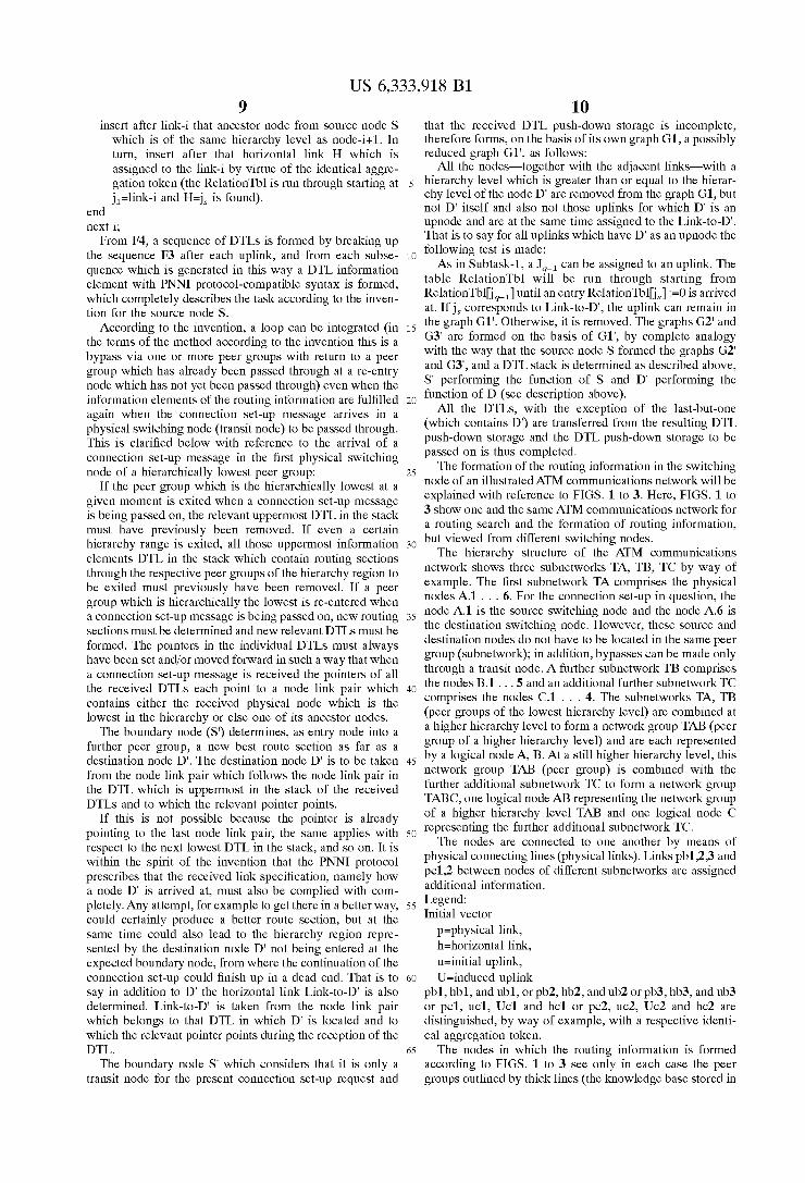
The activity of the transit node B.2 (entry node in the further subnetWork TB): The transit node B.2 receives the folloWing routing infor mation ri:
1O
15
25
35
45
55
65
12 1. DTL: (A, hbl), (B, hb3), (A, Ucl), pointer=2 2. DTL: (AB, hc1), (C, hc2), (AB,x‘00 00 00 00), pointer=1 Node B.2 has stored the netWork Which it can see, as a
graph G1 (B.2)—see FIG. 2, outlined by thick lines: (pb4: B.1,B.2), (pb5: B.1,B.5), (pb6: B.4,B.5), (pb7: B3,
B4), (pb8: B.2,B.3), (ua1: B2, A), (ua2: B3, A), (ua3: B4, A), (hbl: B, A), (hb2: B, A), (hb3: B, A), (Ucl: A, C), (Uc2: A, C), (hc1: C, AB), (hc2: C,
Because the traf?c is transit traf?c, G1‘ (B2) is formed by determining ?rst D‘ (B2) and Link-to-D‘ (B.2):
In the transit node, all the nodes of the hierarchy level Which is greater than or equal to the logical node A and the relevant adjacent links are removed from the graph G1 (B.2), With the exception hoWever of D‘ (B.2) =A itself and excepting those uplinks for Which A is an upnode and Which are correlated With Link-to-D‘ (B.2)=hb3. This produces the graph G1‘ (B.2): (pb4: B.1,B.2), (pb5: B.1,B.5), (pb6: B.4,B.5), (pb7: B3,
B4), (pb8: B.2,B.3), (ua3: B4, A)
Since no blockages at the transit node B1 are knoWn, it is true that graph G1‘ (B.2) =graph G2‘ (B.2). Since it is not possible for any ancestor nodes of B1 to be further aWay from this, it is true that G1‘ (B.2) =G2‘ (B.2) =G3‘ (B2). The Dijkstra algorithm Which is applied yields a sequence
F1:
In the reverse order this results in F2:
The operation to form F3 does not produce any changes, i.e. sequence F2 =sequence F3. Sequence F4 is formed from sequence F3: S‘ (B.2)=B.2, pb8, B.3, pb7, B.4, ua3, B, hb3, A=D‘ (B2) The information elements DTLs of the routing informa
tion ri are formed from sequence F4: 1. DTL: (B.2, pb8), (B.3, pb7), (B.4, ua3), pointer=2 2. DTL: (B, hb3), A=D‘ (B.2), pointer=1
the last (=2.) DTL of Which is not transferred. The folloWing routing information ri is thus sent in the
DTL push-doWn storage format from the entry node B2 to the further node B3 in the further subnetWork TB: 1. DTL, neWly formed:
(B.2, pb8), (B.3, pb7), (B.4, ua3), pointer=2 2. DTL, received and further processed:
(A, hb1), (B, hb3), (A, Ucl), pointer=2 3. DTL, received and further processed:
(AB, hc1), (C, hc2), (AB,x‘00 00 00 00), pointer=1 Activity of the transit node A4 in the ?rst subnetWork TA:
The node A.4 receives the folloWing routing information ri: 1. DTL: (A, hbl), (B, hb3), (A, Ucl), pointer=3 2. DTL: (AB, hc1), (C, hc2), (AB,x‘00 00 00 00), pointer=1 Node A.4 has stored the netWork Which it can see as a
graph G1 (A.4) Which corresponds to the graph G1 (A.1) stored by the source node A.1, see above and see FIG. 1
(outlined in thick lines). Because the traf?c is transit traf?c, G1‘ (A4) is formed by
?rstly determining D‘ (A4) and Link-to-D‘ (A.4):
Link-to-D‘ (A4) = hc1. All the nodes from the hierarchy level Which is greater than or equal to the hierarchy level of D‘ (A4) = C, and the relevant adjoining links, are removed from the graph G1 (A.4), but With the exception of D‘ (A4) = C itself and
US 6,333,918 B1 13
excepting those uplinks for Which D‘ (A4) = C is an upnode and Which are correlated With Link-to-D‘ (A4) = hc1.
Graph G1‘ (A4) is produced: (pa2: A2, A1), (pa3: A.3, A.1), (pa4: A4, A5), (pa5: A5, A1), (pa6: A6, A5),
(ub1: A.2, B), (ub2: A.3, B), (ub3: A.4, B), (uc1: A.5, C), (hb1: B, A), (hb2: B, A), (hb3: B, A), (Uc1: A, C)
The blocked links are removed and this results in graph G2‘ (A.4): (pa2: A2, A1), (pa3: A.3, A.1), (pa4: A4, A5), (ub1: A.2, B), (ub2: A.3, B), (ub3: A.4, B), (uc1: A.5, C), (hb1: B, A), (hb2: B, A), (hb3: B, A), (Uc1: A, C) When all the ancestor nodes still contained are removed
from this, together With the adjoining connecting lines, graph G3‘ (A4) is produced: (pa2: A2, A1), (pa3: A.3, A.1), (pa4: A4, A5), (ub1: A.2, B), (ub2: A.3, B), (ub3: A.4, B), (uc1: A.5, C). By means of Dijkstra routing algorithm, the folloWing
sequence F1 is determined here as the best route from the transit node A4 to the representative C of the additional further subnetWork TC: D‘ (A.4)=C, uc1, A.5, pa4, A.4=S‘ (A.4) By reversing the sequence, the sequence F2 is obtained: S‘ (A.4)=A.4, pa4, A.5, uc1, C=D‘ (A.4)
Since the sequence F2 is never descending in terms of the hierarchy level of the nodes Which occur, the operations for forming the sequence F3 do not produce any changes: F3=F2.
The sequence F4 is acquired from the sequence F3, namely:
The folloWing information elements DTLs of the routing information ri are derived from the sequence F4: 1. DTL: (A.4, pa4), (A.5, uc1), pointer=2 2. DTL: (AB, hc1), (C, x‘00 00 00 00), pointer=1
the last (=2.) DTL of Which is not transferred. The folloWing DTL push-doWn storage contents are thus
transferred from the transit node A4 to the node A5: 1. DTL, neWly formed: (A.4, pa4), (A.5, uc1), pointer=2 2. DTL, received and further processed: (A, hb1), (B, hb3),
(A, Uc1), pointer=3 3. DTL, received and further processed: (AB, hc1), (C, hc2),
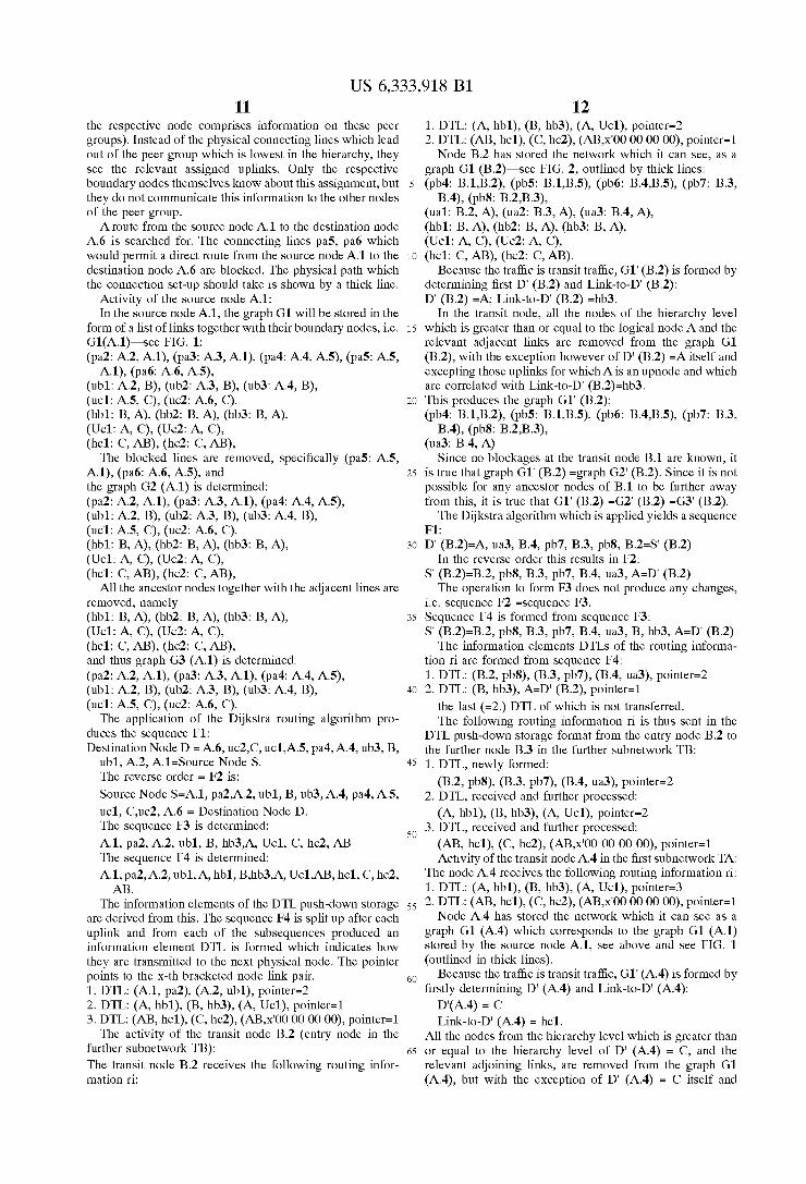
(AB,x‘00 00 00 00), pointer=1 Activity of the transit node C1 in the additional further
subnetWork TC: The node C.1 receives the folloWing routing information ri: 1. DTL: (AB, hc1), (C, hc2), (AB,x‘00 00 00 00), pointer=2. The node C.1 has stored the netWork Which it can see, as
a graph G1 (C.1), see FIG. 3: (pc3: C1, C2), (pc4: C2, C3), (pc5: C3, C4), (pc6: Cl, C 4
(uab1: C.1, AB), (uab2: C.4, AB) (hc1: C, AB), (Hc2: C, AB) Because the traf?c is transit traf?c, G1‘ (C1) is formed by ?rstly determining D‘ (C1) and Link-to-D‘ (C.1):
Link-to-D‘ (C1) = hc2. All the nodes from a hierarchy level Which is greater than
or equal to the hierarchy level of D‘ (C1) = AB, and the relevant adjoining links, are removed from the graph G1 (C.1), but With the exception of D‘ (C1) = C itself and excepting those uplinks for Which D‘ (C1) = AB is an upnode and Which are correlated With Link-to-D‘ (C1) = hc2.
15
25
35
45
55
65
14 Graph G1‘ (C1) is produced: (pc3: C1, C2), (pc4: C2, C3), (pc5: C3, C4), (pc6: C1,
C4), (uab2; C.4, AB)
Since the node C.1 does not ?nd any blocked connecting lines (these are located in the ?rst subnetWork TA), G1‘ (C.1)=G2‘ (C.1). Because no ancestor nodes relating to node C.1 can addi tionally be removed from this, it is true that:
Using the Dijkstra routing algorithm, the node C.1 Will determine as best route the sequence F1:
By reversing the order, sequence F2 is obtained: S‘ (C.1), pc6, C.4, uab2, AB=D‘ (C.1)
Since the sequence F2 is never descending in terms of the hierarchy level of the nodes Which occur, the operations to form the sequence F3 do not produce any changes: F3=F2. The sequence F4 is acquired from the sequence F3,
namely:
The folloWing information elements DTL of the routing information ri are derived from the sequence F4: 1. DTL: (C.1, pc6), (C.4,uab2), pointer=2 2. DTL: (C, hc2), (AB,x‘00 00 00 00) pointer=1 the last (=2.) DTL of Which is not transferred. The folloWing DTL stack is thus transferred from the node
C1 to the further node C4 in the additional further subnet Work TC: 1. DTL, neWly formed: (C.1, pc6), (C.4, uab2), pointer=2 2. DTL, received and further processed: (AB, hc1), (C, hc2),
(AB,x‘00 00 00 00), pointer=2. Activity of the re-entry node A6 for the second re-entry into
the ?rst subnetWork TA: The node A.6 receives the folloWing routing information ri: 1. DTL: (AB, hc1), (C, hc2), (AB,x‘00 00 00 00), pointer=3.
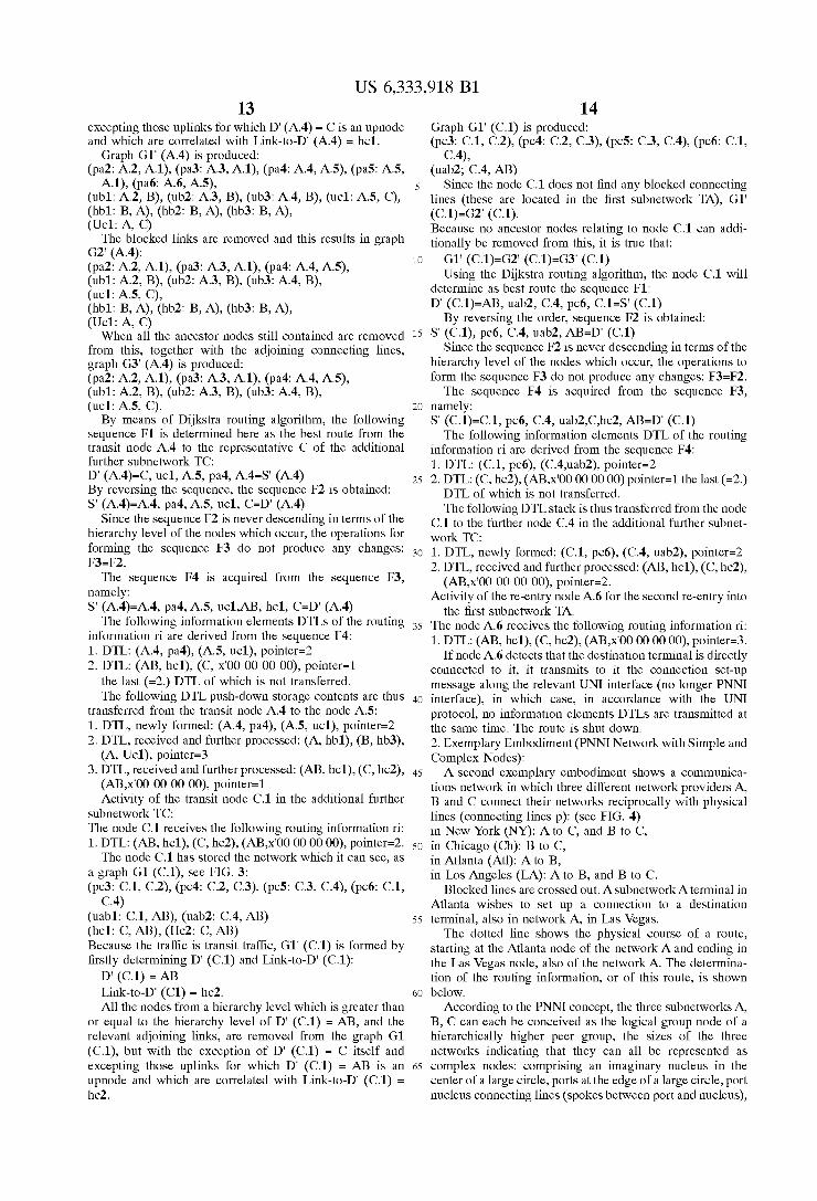
If node A.6 detects that the destination terminal is directly connected to it, it transmits to it the connection set-up message along the relevant UNI interface (no longer PNNI interface), in Which case, in accordance With the UNI protocol, no information elements DTLs are transmitted at the same time. The route is shut doWn. 2. Exemplary Embodiment (PNNI NetWork With Simple and Complex Nodes): A second exemplary embodiment shoWs a communica
tions netWork in Which three different netWork providers A, B and C connect their netWorks reciprocally With physical lines (connecting lines p): (see FIG. 4) in NeW York A to C, and B to C, in Chicago (Ch): B to C, in Atlanta (Atl): A to B, in Los Angeles A to B, and B to C.
Blocked lines are crossed out. AsubnetWorkA terminal in Atlanta Wishes to set up a connection to a destination
terminal, also in netWork A, in Las Vegas. The dotted line shoWs the physical course of a route,
starting at the Atlanta node of the netWork A and ending in the Las Vegas node, also of the netWork A. The determina tion of the routing information, or of this route, is shoWn beloW.
According to the PNNI concept, the three subnetWorks A, B, C can each be conceived as the logical group node of a hierarchically higher peer group, the siZes of the three netWorks indicating that they can all be represented as complex nodes: comprising an imaginary nucleus in the center of a large circle, ports at the edge of a large circle, port nucleus connecting lines (spokes betWeen port and nucleus),
US 6,333,918 B1 15
and port-port connecting lines (bypass exceptions between every two ports). The physical cross-connecting lines between the three networks correspond to so-called hori zontal links (h) (see FIG. 10).
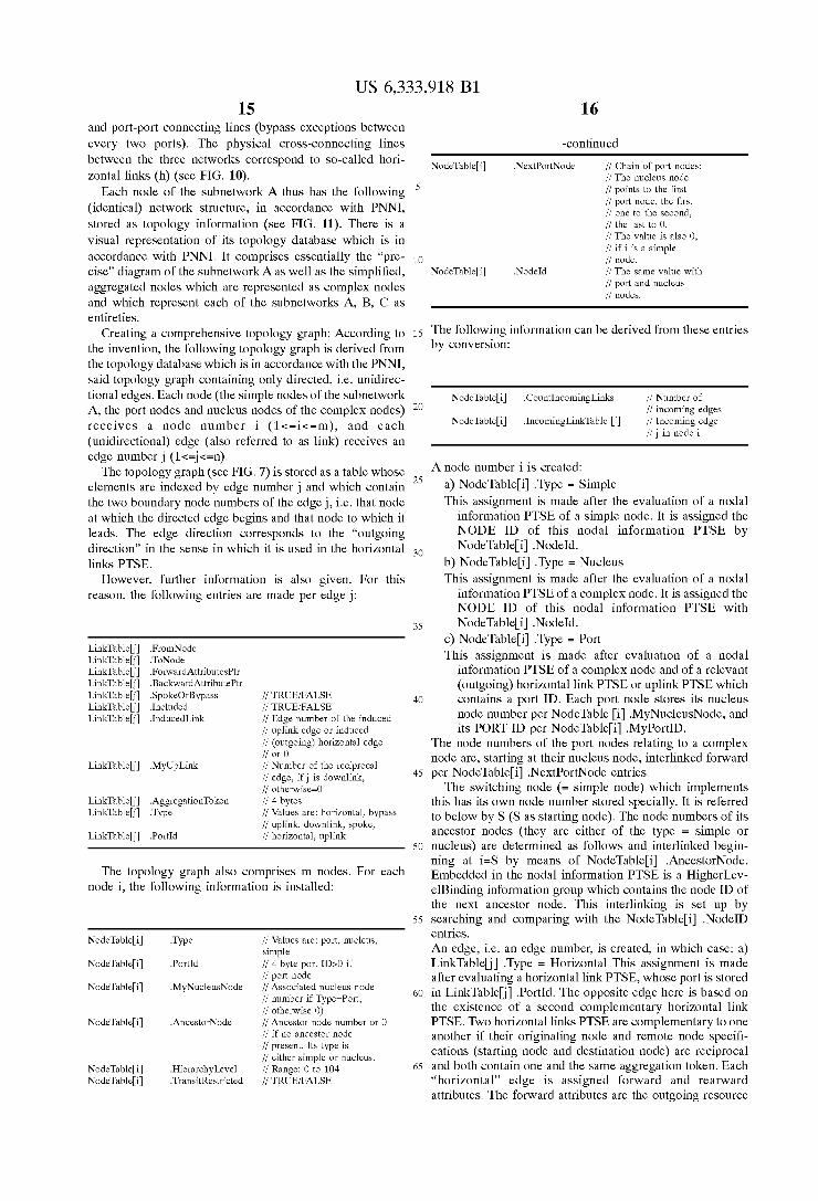
Each node of the subnetwork A thus has the following (identical) network structure, in accordance with PNNI, stored as topology information (see FIG. 11). There is a visual representation of its topology database which is in accordance with PNNI. It comprises essentially the “pre cise” diagram of the subnetworkA as well as the simpli?ed, aggregated nodes which are represented as complex nodes and which represent each of the subnetworks A, B, C as entireties.
Creating a comprehensive topology graph: According to the invention, the following topology graph is derived from the topology database which is in accordance with the PNNI, said topology graph containing only directed, i.e. unidirec tional edges. Each node (the simple nodes of the subnetwork A, the port nodes and nucleus nodes of the complex nodes) receives a node number i (1<=i<=m), and each (unidirectional) edge (also referred to as link) receives an edge numberj (1<=j<=n).
The topology graph (see FIG. 7) is stored as a table whose elements are indexed by edge number j and which contain the two boundary node numbers of the edge j, ie that node at which the directed edge begins and that node to which it leads. The edge direction corresponds to the “outgoing direction” in the sense in which it is used in the horizontal links PTSE.
However, further information is also given. For this reason, the following entries are made per edge
LinkTable[j] .FromNode LinkTable[j] .ToNode LinkTable[j] .ForwardAttributesPtr LinkTable[j] .BackwardAttributePtr LinkTable[j] .SpokeOrBypass // TRUE/FALSE LinkTable[j] .Included // TRUE/FALSE LinkTable[j] .InducedLink // Edge number of the induced
// uplink edge or induced // (outgoing) horizontal edge // or O
LinkTable[j] .MyUpLink // Number of the reciprocal // edge, ifj is downlink, // otherwise=0
LinkTable[j] .AggregationToken // 4 bytes LinkTable[j] .Type // Values are: horizontal, bypass
// uplink, downlink, spoke, LinkTable[j] .PortId // horizontal, uplink
The topology graph also comprises m nodes. For each node i, the following information is installed:
NodeTable[i] .Type // Values are: port, nucleus, simple
NodeTable[i] .PortId // 4 byte port ID>O if // port node
NodeTable[i] .MyNucleusNode // Associated nucleus node // number if Type=Port, // otherwise 0)
NodeTable[i] .AncestorNode // Ancestor node number or O // if no ancestor node // present. Its type is // either simple or nucleus.
NodeTable[i] .HierarchyLevel // Range: 0 to 104 NodeTable[i] .TransitRestricted // TRUE/FALSE
15
3O
35
45
55
65
16
-continued
NodeTable[i] .NextPortNode // Chain of port nodes: // The nucleus node // points to the ?rst // port node, the ?rst // one to the second, // the last to O. // The value is also 0, // ifi is a simple // node. // The same value with // port and nucleus // nodes.
NodeTable[i] .NodeId
The following information can be derived from these entries by conversion:
NodeTable[i] .CountIncomingLinks // Number of // incoming edges
NodeTable[i] .IncomingLinkTable // Incoming edge //j in node i
A node number i is created:
a) NodeTable[i] .Type = Simple This assignment is made after the evaluation of a nodal
information PTSE of a simple node. It is assigned the NODE ID of this nodal information PTSE by NodeTable[i] .NodeId.
b) NodeTable[i] .Type = Nucleus This assignment is made after the evaluation of a nodal
information PTSE of a complex node. It is assigned the NODE ID of this nodal information PTSE with NodeTable[i] .NodeId.
c) NodeTable[i] .Type = Port This assignment is made after evaluation of a nodal
information PTSE of a complex node and of a relevant (outgoing) horizontal link PTSE or uplink PTSE which contains a port ID. Each port node stores its nucleus node number per NodeTable .MyNucleusNode, and its PORT ID per NodeTable[i] .MyPortID.
The node numbers of the port nodes relating to a complex node are, starting at their nucleus node, interlinked forward per NodeTable[i] .NextPortNode entries.
The switching node (= simple node) which implements this has its own node number stored specially. It is referred to below by S (S as starting node). The node numbers of its ancestor nodes (they are either of the type = simple or nucleus) are determined as follows and interlinked begin ning at i=S by means of NodeTable[i] .AncestorNode. Embedded in the nodal information PTSE is a HigherIJev elBinding information group which contains the node ID of the next ancestor node. This interlinking is set up by searching and comparing with the NodeTable[i] .NodeID entries. An edge, ie an edge number, is created, in which case: a) LinkTableD] .Type = Horizontal This assignment is made after evaluating a horizontal link PTSE, whose port is stored in LinkTable?] .PortId. The opposite edge here is based on the existence of a second complementary horizontal link PTSE. Two horizontal links PTSE are complementary to one another if their originating node and remote node speci? cations (starting node and destination node) are reciprocal and both contain one and the same aggregation token. Each “horizontal” edge is assigned forward and rearward attributes. The forward attributes are the outgoing resource