method 0050 isokinetic hcl/cl 2 emission ... 0050 - 1 revision 0 december 1996 method 0050...
TRANSCRIPT

CD-ROM 0050 - 1 Revision 0December 1996
METHOD 0050
ISOKINETIC HCl/Cl EMISSION SAMPLING TRAIN2
1.0 SCOPE AND APPLICATION
1.1 This method describes the collection of hydrogen chloride (HCl, CAS Registry Number7647-01-0) and chlorine (Cl , CAS Registry Number 7782-50-5) in stack gas emission samples from2
hazardous waste incinerators and municipal waste combustors. The collected samples are analyzedusing Method 9057. This method collects the emission sample isokinetically and is thereforeparticularly suited for sampling at sources, such as those controlled by wet scrubbers, emitting acidparticulate matter (e.g., HCl dissolved in water droplets). A midget impinger train sampling methoddesigned for sampling sources of HCl/Cl emissions not in particulate form is presented in Method2
0051. The method has potential for collection of all halogens and halogen acids, but has not yetbeen fully evaluated for that use. For analytical determination of additional halides, Method 9056 isused, rather than Method 9057.
1.2 This method is not acceptable for demonstrating compliance with HCl emissionstandards less than 20 ppm.
1.3 This method may also be used to collect samples for subsequent determination ofparticulate emissions (Method 5, see Ref. 1) following the additional sampling procedures described.
2.0 SUMMARY OF METHOD
2.1 Gaseous and particulate pollutants are withdrawn from an emission source and arecollected in an optional cyclone, on a filter, and in absorbing solutions. The cyclone collects anyliquid droplets and is not necessary if the source emissions do not contain liquid droplets. TheTeflon mat or quartz-fiber filter collects other particulate matter including chloride salts. Acidic andalkaline absorbing solutions collect gaseous HCl and Cl , respectively. Following sampling of2
emissions containing liquid droplets, any HCl/Cl dissolved in the liquid in the cyclone and/or on the2
filter is vaporized to gas and ultimately collected in the impingers by pulling Ascarite II conditionedR
ambient air through the sampling train. In the acidified water absorbing solution, the HCl gas issolubilized and forms chloride (Cl ) ions. The Cl gas present in the emissions has a very low-
2
solubility in acidified water and passes through to the alkaline absorbing solution where it undergoeshydrolysis to form a proton (H ), Cl , and hypochlorous acid (HClO). The (Cl ) ions in the separate+ - -
solutions are measured by ion chromatography (Method 9057). If desired, the particulate matterrecovered from the filter and the probe is analyzed following the procedures in Method 5.
2.2 The stoichiometry of HCl and Cl collection in the sampling train is as follows: In the2acidified water absorbing solution, the HCl gas is solubilized and forms chloride ions (Cl ) according-
to the following formula:
HCl + H O = H O + Cl2 3+ -
The Cl gas present in the emissions has a very low solubility in acidified water and passes through2to the alkaline absorbing solution where it undergoes hydrolysis to form a proton (H ), Cl , and+ -
hypochlorous acid (HClO) as shown:

CD-ROM 0050 - 2 Revision 0December 1996
H O + Cl = H + Cl + HClO2 2+ -
Sodium thiosulfate solution is added to the contents of the hydroxide filled impingers, in orderto promote the following reaction.
S O + 4OCl + 2OH = 2SO + 4Cl + H O2 3 4 2-2 - - -2 -
Conversion of all the original Cl to the stable Cl ion, and appropriate adjustment of the2 -
analysis calculations, removes the possibility of partial reduction of OCl to Cl and the- -
resulting high bias to the results.
3.0 INTERFERENCES
3.1 Volatile materials which produce chloride ions upon dissolution during sampling areobvious interferences in the measurement of HCl. One interferant for HCl is diatomic chlorine (Cl )2
gas which disproportionates to HCl and hypochlorous acid (HClO) upon dissolution in water. Cl gas2
exhibits a low solubility in water, however, and the use of acidic rather than neutral or basic solutionsfor collection of hydrogen chloride gas greatly reduces the dissolution of any chlorine present.
4.0 APPARATUS AND MATERIALS
4.1 Sampling Train.
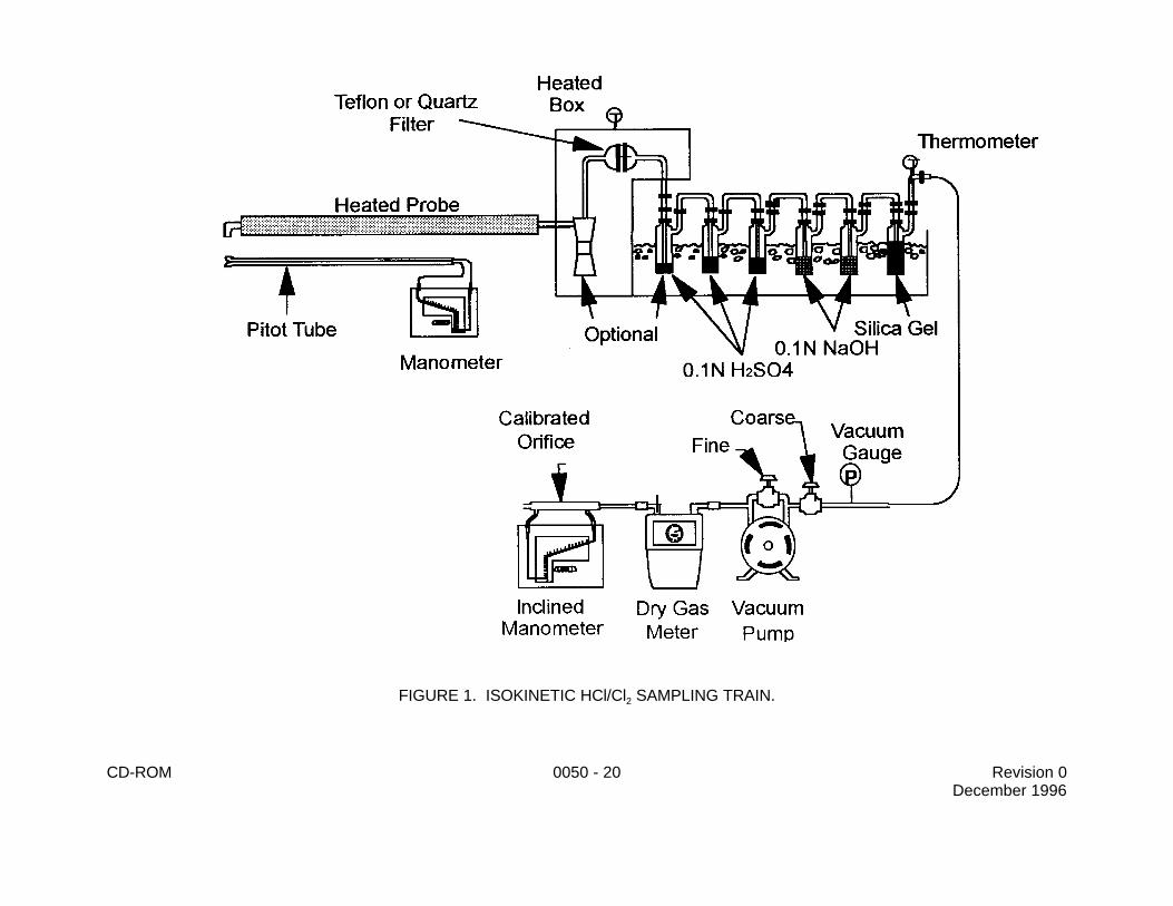
4.1.1 A schematic of the sampling train used in this method is shown in Figure 1.This sampling train configuration is adapted from Method 5 and Method 0010 procedures,and, as such, the majority of the required equipment is identical to that used in Method 0010determinations. The new components required are a glass nozzle and probe, a Teflon union,a quartz-fiber or Teflon mat filter (see Section 5.5), a Teflon frit, and acidic and alkalineabsorbing solutions.
4.1.2 Construction details for the basic train components are provided in Section3.4 of EPA's Quality Assurance Handbook, Volume III (Reference 2); commercial models ofthis equipment are also available. Additionally, the following subsections identify allowabletrain configuration modifications.
4.1.3 Basic operating and maintenance procedures for the sampling train are alsodescribed in Reference 2. As correct usage is important in obtaining valid results, all usersshould refer to Reference 2 and adopt the operating and maintenance procedures outlinedtherein unless otherwise specified. The sampling train consists of the components detailedbelow.
4.1.3.1 Probe nozzle. Glass with sharp, tapered (30 angle) leading edge.o
The taper shall be on the outside to preserve a constant I.D. The nozzle shall bebuttonhook or elbow design. The nozzle should be coupled to the probe liner usinga Teflon union. It is recommended that a stainless steel nut be used on this union.In cases where the stack temperature exceeds 210EC (410EF), a one-piece glassnozzle/liner assembly must be used. A range of nozzle sizes suitable for isokineticsampling should be available. Each nozzle shall be calibrated according to theprocedures outlined in Method 5.

CD-ROM 0050 - 3 Revision 0December 1996
4.1.3.2 Probe liner. Borosilicate or quartz-glass tubing with a heated systemcapable of maintaining a gas temperature of 120 ± 14EC (248 ± 25EF) at the exit endduring sampling. Because the actual temperature at the outlet of the probe is notusually monitored during sampling, probes constructed and calibrated according tothe procedure in Reference 2 are considered acceptable. Either borosilicate orquartz-glass probe liners may be used for stack temperatures up to about 480EC(900EF). Quartz liners shall be used for temperatures between 480 and 900EC (900and 1650EF). (The softening temperature for borosilicate is 820EC (1508EF), and forquartz 1500EC (2732EF).) Water-cooling of the stainless steel sheath will benecessary at temperatures approaching and exceeding 500EC.
4.1.3.3 Pitot tube. Type S, as described in Section 2.1 of Method 2(Reference 1). The pitot tube shall be attached to the probe to allow constantmonitoring of the stack-gas velocity. The impact (high-pressure) opening plane ofthe pitot tube shall be even with or above the nozzle entry plane (see Section 3.1.1of Reference 2) during sampling. The Type S pitot tube assembly shall have aknown coefficient, determined as outlined in Section 3.1.1 of Reference 2.
4.1.3.4 Differential pressure gauge. Inclined manometer or equivalent deviceas described in Section 2.2 of Method 2. One manometer shall be used for velocity-head (delta P) readings and the other for orifice differential pressure (delta H)readings.
4.1.3.5 Cyclone (optional), glass.
4.1.3.6 Filter holder. Borosilicate glass, with a Teflon frit filter support anda sealing gasket. The sealing gasket shall be constructed of Teflon or equivalentmaterials. The holder design shall provide a positive seal against leakage at anypoint along the filter circumference. The holder shall be attached immediately to theoutlet of the cyclone.
4.1.3.7 Filter heating system. Any heating system capable of maintaining atemperature of 120 ± 14EC (248 ± 25EF) around the filter holder and cyclone duringsampling. A temperature gauge capable of measuring temperature to within 3EC(5.4EF) shall be installed so that the temperature around the filter holder can beregulated and monitored during sampling.
4.1.3.8 Impinger train. The following system shall be used to determine thestack gas moisture content and to collect HCl and Cl : five or six impingers2
connected in series with leak-free ground glass fittings or any similar leak-free non-contaminating fittings. The first impinger shown in Figure 1 (knockout or condensateimpinger) is optional and is recommended as a water knockout trap for use undertest conditions which require such a trap. If used, this impinger should beconstructed as described below for the alkaline impingers, but with a shortened stem,and should contain 50 ml of 0.05 M H SO . The following two impingers (acid2 4
impingers which each contain 100 ml of 0.05 M H SO ) shall be of the Greenburg-2 4
Smith design with the standard tip (see Method 0010, Section 4). The next twoimpingers (alkaline impingers which each contain 100 mL of 0.1 M NaOH) and thelast impinger (containing silica gel) shall be of the Greenburg-Smith design modified

CD-ROM 0050 - 4 Revision 0December 1996
by replacing the tip with a 1.3-cm (½-in.) I.D. glass tube extending about 1.3 cm (½in.) from the bottom of the impinger (see Method 5, Section 4).
The condensate, acid, and alkaline impingers shall contain known quantities of theappropriate absorbing reagents. The last impinger shall contain a known weight ofsilica gel or equivalent desiccant.
4.1.3.9 Metering system. The necessary components are a vacuum gauge,leak-free pump, thermometers capable of measuring temperature to within 3EC(5.4EF), dry-gas meter capable of measuring volume to within 1%, an orifice meter(rate meter), and related equipment, as shown in Figure 1. At a minimum, the pumpshould be capable of 113 m /min (4 cfm) free flow, and the dry-gas meter should3
have a recording capacity of 0-28.3 m (0-999.9 ft ) with a resolution of 0.142 liters3 3
(0.005 ft ). Other metering systems capable of maintaining sampling rates within3
10% of isokineticity and of determining sample volumes to within 2% may be used.The metering system must be used in conjunction with a pitot tube to enable checksof isokinetic sampling rates.
4.1.3.10 Barometer. Mercury, aneroid, or other barometer capable ofmeasuring atmospheric pressure to within 2.5 mm Hg (0.1 in. Hg). In many cases,the barometric reading may be obtained from a nearby National Weather Servicestation, in which case the station value (which is the absolute barometric pressure)is requested and an adjustment for elevation differences between the weather stationand sampling point is applied at a rate of minus 2.5 mm Hg (0.1 in. Hg) per 30-m(100 ft) elevation increase (vice versa for elevation decrease).
4.1.3.11 Gas density determination equipment. Temperature sensor andpressure gauge (as described in Sections 2.3 and 2.4 of Method 2), and gasanalyzer, if necessary (as described in Method 3, Reference 1). The temperaturesensor ideally should be permanently attached to the pitot tube or sampling probe ina fixed configuration such that the tip of the sensor extends beyond the leading edgeof the probe sheath and does not touch any metal. Alternatively, the sensor may beattached just prior to use in the field. Note, however, that if the temperature sensoris attached in the field, the sensor must be placed in an interference-freearrangement with respect to the Type S pitot tube openings (see Method 2, Figure2-7). As a second alternative, if the stack gas is saturated, the stack temperaturemay be measured at a single point near the center of the stack.
4.1.3.12 Ascarite tube for conditioning ambient air. Tube tightly packed withapproximately 150 g of fresh 8 to 20 mesh Ascarite II sodium hydroxide coatedR
silica, or equivalent, to dry and remove acid gases from the ambient air used toremove moisture from the filter and optional cyclone. The inlet and outlet ends of thetube should be packed with at least 1 cm thickness of glass wool or filter materialsuitable to prevent escape of Ascarite II fines. Fit one end with flexible tubing, etc.to allow connection to probe nozzle.

CD-ROM 0050 - 5 Revision 0December 1996
4.2 Sample Recovery.
4.2.1 Probe liner. Probe and nozzle brushes; nylon (Teflon) bristle brushes withstainless steel wire handles are required. The probe brush shall have extensions of stainlesssteel, Teflon, or inert material at least as long as the probe. The brushes shall be properlysized and shaped to brush out the probe liner and the probe nozzle.
4.2.2 Wash bottles. Two. Polyethylene or glass, 500 mL or larger.
4.2.3 Glass sample storage containers. Glass, 500- or 1,000-mL. Screw-capliners shall be Teflon and constructed so as to be leak-free. Narrow-mouth glass bottleshave been found to exhibit less tendency toward leakage.
4.2.4 Petri dishes. Glass or plastic sealed around the circumference with Teflontape, for storage and transport of filter samples.
4.2.5 Graduated cylinder and/or balances. To measure condensed water to thenearest 1 mL or 1 g. Graduated cylinders shall have subdivisions not >2 mL. Laboratorytriple-beam balances capable of weighing to ± 0.5 g or better are required.
4.2.6 Plastic storage containers. Screw-cap polypropylene or polyethylenecontainers to store silica gel.
4.2.7 Funnel and rubber policeman. To aid in transfer of silica gel to container (notnecessary if silica gel is weighed in field).
4.2.8 Funnels. Glass, to aid in sample recovery.
5.0 REAGENTS
5.1 Reagent grade inorganic chemicals shall be used in all tests. Unless otherwiseindicated, it is intended that all reagents shall conform to the specifications of the Committee onAnalytical Reagents of the American Chemical Society, where such specifications are available.Other grades may be used, provided it is first ascertained that the reagent is of sufficiently high purityto permit its use without lessening the accuracy of the determination.
5.2 Reagent water. All references to water in the method refer to reagent grade wateras defined in Chapter One unless otherwise specified. It is advisable to analyze a blank sample ofthis water prior to sampling, since the reagent blank values obtained during the field sample analysismust be less than 10 percent of the sample values.
5.3 Sulfuric acid (0.05 M), H SO . Used as the HCl absorbing reagent in the impinger2 4
train. To prepare 1 L, slowly add 2.80 mL of concentrated H SO to about 900 mL of water while2 4
stirring, and adjust the final volume to 1-L using additional water. Shake well to mix the solution.It is advisable to analyze a blank sample of this reagent prior to sampling, since the reagent blankvalues obtained during the field sample analysis must be less than 10 percent of the sample values.
5.4 Sodium hydroxide (0.1 M), NaOH. Used as the Cl absorbing reagent in the impinger2
train. To prepare 1 L, dissolve 4.00 g of solid NaOH in about 900 mL of water and adjust the final

CD-ROM 0050 - 6 Revision 0December 1996
volume to 1-L using additional water. Shake well to mix the solution. It is advisable to analyze ablank sample of this reagent prior to sampling, since the reagent blank values obtained during thefield sample analysis must be less than 10 percent of the sample values.
5.5 Filter. Quartz-fiber or Teflon mat (e.g., Pallflex TX40HI45) filter, or equivalent.R
5.6 Silica gel. Indicating type, 6-16 mesh. If previously used, dry at 175EC (350EF) for2 hours before using. New silica gel may be used as received. Alternatively, other types ofdesiccants may be used if equivalence can be demonstrated.
5.7 Acetone. When using this train for determination of particulate emissions, reagentgrade acetone, # 0.001 percent residue, in glass bottles is required. Acetone from metal containersgenerally has a high residue blank and should not be used. Sometimes suppliers transfer acetoneto glass bottles from metal containers; thus, acetone blanks shall be run prior to field use and onlyacetone with low blank values (# 0.001 percent) shall be used. In no case shall a blank valuegreater than 0.001 percent of the weight of acetone used be subtracted from the sample weight.
5.8 Crushed ice. Quantities ranging from 10-50 lb may be necessary during a samplingrun, depending on ambient air temperature.
5.9 Screw-on connectors, Teflon sleeves on ground-glass joints, or other greaselessfittings should be used.
5.10 Sodium thiosulfate (0.5 M), Na S O . Used as the reducing agent added to the2 2 3
sodium hydroxide filled impingers to promote the reaction given in Section 2.0. Buy premixedreagent grade, as free of chloride as possible.
6.0 SAMPLE COLLECTION, PRESERVATION, AND HANDLING
6.1 Sample collection is described in this method. The analytical procedures for HCl andCl are described in Method 9057 and for particulate matter in Method 0100.2
6.2 Samples should be stored in clearly labeled, tightly sealed containers between samplerecovery and analysis. They may be analyzed up to four weeks after collection.
7.0 PROCEDURE
7.1 Preparation for Field Test.
7.1.1 All sampling equipment shall be maintained and calibrated the proceduresdescribed in Section 3.4.2 of EPA's Quality Assurance Handbook, Volume III (Reference 2)and in Methods 1-5 (Reference 1).
7.1.2 Weigh several 200-300-g portions of silica gel in airtight containers to thenearest 0.5-g. Record on each container the total weight of the silica gel plus containers.As an alternative to preweighing the silica gel, it may instead be weighed directly in theimpinger just prior to train assembly.

CD-ROM 0050 - 7 Revision 0December 1996
7.1.3 Check filters visually against light for irregularities and flaws or pinhole leaks.Label the shipping containers (glass or plastic Petri dishes) and keep the filters in thesecontainers at all times except during sampling (and weighing for particulate analysis).
7.1.4 If a particulate determination will be conducted, desiccate the filters at 20 ±5.6EC (68 ± 10EF) and ambient pressure for at least 24 h, and weigh at intervals of at least6 h to a constant weight (i.e., <0.5-mg change from previous weighing), recording results tothe nearest 0.1 mg. During each weighing, the filter must not be exposed for more than a2-min period to the laboratory atmosphere and relative humidity above 50%. Alternatively,the filters may be oven-dried at 105EC (220EF) for 2-3 h, desiccated for 2 h, and weighed.
7.2 Preliminary Field Determinations.
7.2.1 Select the sampling site and the minimum number of sampling pointsaccording to Method 1. Determine the stack pressure, temperature, and range of velocityheads using Method 2. It is recommended that a leak-check of the pitot lines (see Method2) be performed. Determine the stack-gas moisture content using Method 4 or itsalternatives to establish estimates of isokinetic sampling rate settings. Determine the stackgas dry molecular weight, as described in Method 2, Section 3. If integrated Method 3(Reference 1) sampling is used for molecular weight determination, the integrated bagsample shall be taken simultaneously with, and for the same total length of time as thesample run.
7.2.2 Select a nozzle size based on the range of velocity heads so that it is notnecessary to change the nozzle size to maintain isokinetic sampling rates. During the run,do not change the nozzle. Ensure that the proper differential pressure gauge is chosen forthe range of velocity heads encountered (see Section 2 of Method 2).
7.2.3 Select a suitable probe liner and probe length so that all traverse points canbe sampled. For large stacks, to reduce the length of the probe, consider sampling fromopposite sides of the stack.
7.2.4 The total sampling time should be two hours. Allocate the same time to alltraverse points defined by Method 1. To avoid timekeeping errors, the length of timesampled at each traverse point should be an integer or an integer plus one-half min. Sizethe condensate impinger for the expected moisture catch or be prepared to empty it duringthe run.
7.3 Preparation of Sampling Train.
7.3.1 Add 50 mL of 0.05 M H SO to the condensate impinger, if used. Place 1002 4
mL of 0.05 M H SO in each of the next two impingers. Place 100 mL of 0.1 M NaOH in2 4
each of the following two impingers. It is essential that the NaOH filled impingers bemaintained strongly basic throughout the sampling run. In highly acid stack environments,this may require measures such as stronger base, more volume of basic solution, orchangeout of impinger liquid during the run. When in doubt, the pH of the solution shouldbe monitored frequently or continuously. Finally, transfer approximately 200-300 g ofpreweighed silica gel from its container to the last impinger. More silica gel may be used,but care should be taken to ensure that it is not entrained and carried out from the impinger

CD-ROM 0050 - 8 Revision 0December 1996
during sampling. Place the silica gel container in a clean place for later use in the samplerecovery. Alternatively, the weight of the silica gel plus impinger may be determined to thenearest 0.5 g and recorded.
7.3.2 Using a tweezer or clean disposable surgical gloves, place a labeled(identified) filter (weighed, if particulate matter is to be determined) in the filter holder. Besure that the filter is properly centered and the gasket properly placed to prevent the samplegas stream from circumventing the filter. Check the filter for tears after assembly iscompleted.
7.3.3 To use glass liners, install the selected nozzle using a Viton-A O-ring whenstack temperatures are <260EC (500EF) and a woven glass fiber gasket when temperaturesare higher. Other connecting systems utilizing Teflon ferrules may be used. Mark the probewith heat-resistant tape or by some other method to denote the proper distance into the stackor duct for each sampling point.
7.3.4 Set up the train as in Figure 1. Connect temperature sensors to theappropriate potentiometer/display unit. Check all temperature sensors at ambienttemperature.
7.3.5 Place crushed ice around the impingers.
7.3.6 Turn on and set the filter and probe heating systems at the desired operatingtemperatures. Allow time for the temperatures to stabilize.
7.4 Leak-check Procedures.
7.4.1 Pretest leak-check. A pretest leak-check is recommended, but not required.If the tester opts to conduct the pretest leak-check, the following procedure shall be used.
7.4.1.1 If a Viton A O-ring or other leak-free connection is used in assemblingthe probe nozzle to the probe liner, leak-check the train at the sampling site byplugging the nozzle and pulling a 380-mm Hg (15-in. Hg) vacuum.
NOTE: A lower vacuum may be used, provided that it is not exceeded during the test.
7.4.1.2 If a woven glass fiber gasket is used, do not connect the probe to thetrain during the leak-check. Instead, leak-check the train by first plugging the inlet tothe cyclone, if used, or the filter holder and pulling a 380-mm Hg (15-in. Hg) vacuum(see NOTE above). Then, connect the probe to the train and leak-check at about 25-mm Hg (1-in. Hg) vacuum; alternatively, leak-check the probe with the rest of thesampling train in one step at 380-mm Hg (15-in. Hg) vacuum. Leakage rates inexcess of 4% of the average sampling rate or 0.00057 m /min (0.02 cfm), whichever3
is less, are unacceptable.
7.4.1.3 The following leak-check instructions for the sampling train may behelpful. Start the pump with bypass valve fully open and coarse adjust valvecompletely closed. Partially open the coarse adjust valve and slowly close thebypass valve until the desired vacuum is reached. Do not reverse direction of the

CD-ROM 0050 - 9 Revision 0December 1996
bypass valve; this will cause water to back up into the filter holder. If the desiredvacuum is exceeded, either leak-check at this higher vacuum or end the leak-check,as shown below, and start over.
7.4.1.4 When the leak-check is completed, first slowly remove the plug fromthe inlet to the probe, cyclone, or filter holder and immediately turn off the vacuumpump. This prevents the liquid in the impingers from being forced backward into thefilter holder and silica gel from being entrained backward into the fifth impinger.
7.4.2 Leak-checks during sample run. If, during the sampling run, a component(e.g., filter assembly or impinger) change becomes necessary or a port change is conducted,a leak-check shall be conducted immediately after the interruption of sampling and beforethe change is made. The leak-check shall be conducted according to the procedure outlinedin Section 7.4.1, except that it shall be conducted at a vacuum greater than or equal to themaximum value recorded up to that point in the test. If the leakage rate is found to be nogreater than 0.00057 m /min (0.02 cfm) or 4% of the average sampling rate (whichever is3
less), the results are acceptable. If a higher leakage rate is obtained, the tester shall voidthe sampling run. Immediately after a component change or port change, and beforesampling is reinitiated, another leak-check similar to a pre-test leak-check is recommended.
7.4.3 Post-test leak-check. A leak-check is mandatory at the conclusion of eachsampling run. The leak-check shall be done using the same procedures as those with thepre-test leak-check, except that it shall be conducted at a vacuum greater than or equal tothe maximum value reached during the sampling run. If the leakage rate is found to be nogreater than 0.00057 m /min (0.02 cfm) or 4% of the average sampling rate (whichever is3
less), the results are acceptable. If a higher leakage rate is obtained, the tester shall voidthe sampling run.
7.5 Train Operation.
7.5.1 During the sampling run, maintain an isokinetic sampling rate to within 10%of true isokinetic. Maintain a temperature around the filter and (cyclone, if used) of 120 ±14EC (248 ± 25EF).
7.5.2 For each run, record the data required on a data sheet such as the one shownin Figure 2. Be sure to record the initial dry gas meter reading. Record the dry gas meterreadings at the beginning and end of each sampling time increment, when changes in flowrates are made before and after each leak-check, and when sampling is halted. Take otherreadings required by Figure 2 at least once at each sample point during each time incrementand additional readings when significant changes (20% variation in velocity head readings)necessitate additional adjustments in flow rate. Level and zero the manometer. Because themanometer level and zero may drift due to vibrations and temperature changes, makeperiodic checks during the traverse.
7.5.3 Clean the stack access ports prior to the test run to eliminate the chance ofsampling deposited material. To begin sampling, remove the nozzle cap, verify that the filterand probe heating systems are at the specified temperature, and verify that the pitot tubeand probe are positioned properly. Position the nozzle at the first traverse point, with the tippointing directly into the gas stream. Immediately start the pump and adjust the flow to

CD-ROM 0050 - 10 Revision 0December 1996
isokinetic conditions using a calculator or a nomograph. Nomographs are designed for usewhen the Type S pitot tube coefficient is 0.84 and the stack gas equivalent density (drymolecular weight) is equal to 29 ± 4. If the stack gas molecular weight and the pitot tubecoefficient are outside the above ranges, do not use the nomographs unless appropriatesteps are taken to compensate for the deviations (see Reference 3).
7.5.4 When the stack is under significant negative pressure (equivalent to theheight of the impinger stem), take care to close the coarse adjust valve before inserting theprobe into the stack, to prevent water from backing into the filter holder. If necessary, thepump may be turned on with the coarse adjust valve closed.
7.5.5 When the probe is in position, block off the openings around the probe andstack access port to prevent unrepresentative dilution of the gas stream.
7.5.6 Traverse the stack cross section, as required by Method 1, being careful notto bump the probe nozzle into the stack walls when sampling near the walls or whenremoving or inserting the probe through the access port, in order to minimize the chance ofextracting deposited material.
7.5.7 During the test run, make periodic adjustments to keep the temperaturearound the filter holder (and cyclone, if used) at the proper level. Add more ice, and, ifnecessary, salt to maintain a temperature of <20EC (68EF) at the condenser/silica gel outlet.Also, periodically check the level and zero of the manometer.
7.5.8 If the pressure drop across the filter becomes too high, making isokineticsampling difficult to maintain, it may be replaced in the midst of a sample run. Using anothercomplete filter holder assembly is recommended, rather than attempting to change the filteritself. After a new filter assembly is installed, conduct a leak-check. If determined, the totalparticulate weight shall include the summation of all filter assembly catches.
7.5.9 If the condensate impinger becomes too full, it may be emptied, rechargedwith 50 mL of 0.05 M H SO , and replaced during the sample run. The condensate emptied2 4
must be saved and included in the measurement of the volume of moisture collected andincluded in the sample for analysis. The additional 50 mL of absorbing reagent must alsobe considered in calculating the moisture. After the impinger is reinstalled in the train,conduct a leak-check.
7.5.10 A single train shall be used for the entire sample run, except in cases wheresimultaneous sampling is required in two or more separate ducts or at two or more differentlocations within the same duct, or in cases where equipment failure necessitates a changeof trains.
7.5.11 Note that when two or more trains are used, separate analyses of theparticulate catch (if applicable) and the HCl and Cl impinger catches from each train shall2
be performed, unless identical nozzle sizes were used on all trains. In that case, theparticulate catch and the HCl and Cl impinger catches from the individual trains may be2
combined, and a single particulate analysis and single HCl and Cl analyses of the impinger2
contents may be performed.

CD-ROM 0050 - 11 Revision 0December 1996
7.5.12 At the end of the sample run, turn off the coarse adjust valve, remove theprobe and nozzle from the stack, turn off the pump, record the final dry gas meter reading.
7.5.13 If there is any possibility that liquid has collected in the glass cyclone and/oron the filter, connect the Ascarite tube at the probe inlet and operate the train with the filterheating system at 120 ± 14EC (248 ± 25EF) at a low flow rate (e.g., ªH = 1) sufficient tovaporize the liquid and purge any HCl in the cyclone or on the filter and pull it through thetrain into the impingers. After 30 minutes, turn off the flow, remove the Ascarite tube, andexamine the cyclone and filter for any visible moisture. If moisture is visible, repeat this stepfor 15 minutes. A 45 minute cyclone purge is not effective for removing greater than 25 mLof solution from the cyclone. Also, a 45 minute purge is more effective when the filter andprobe temperatures are increased to 177°C. (See "Laboratory Evaluation of Method 0050 forHydrogen Chloride").
7.5.14 Conduct a post-test leak-check. Also, leak-check the pitot lines as describedin Method 2. The lines must pass this leak-check in order to validate the velocity-head data.
7.5.15 If the moisture value is available, calculate percent isokineticity (see Section7.7.10) to determine whether the run was valid or another test run should be conducted.
7.6 Sample Recovery
7.6.1 Allow the probe to cool. When the probe can be handled safely, wipe off allthe external surfaces of the tip of the probe nozzle and place a cap over the tip. Do not capthe probe tip tightly while the sampling train is cooling down because this will create avacuum in the filter holder, drawing water from the impingers into the holder.
7.6.2 Before moving the sampling train to the cleanup site, remove the probe andcap the open outlet, being careful not to lose any condensate that might be present. Cap thefilter or cyclone inlet. Remove the umbilical cord from the last impinger and cap theimpinger. If a flexible line is used between the first impinger and the filter holder, disconnectit at the filter holder and let any condensed water drain into the first impinger. Cap the filterholder outlet and the impinger inlet. Ground glass stoppers, plastic caps, serum caps, Teflontape, Parafilm , or aluminum foil may be used to close these openings.R
7.6.3 Transfer the probe and filter/impinger assembly to the cleanup area. Thisarea should be clean and protected from the weather to minimize sample contamination orloss.
7.6.4 Save portions of all washing solutions used for cleanup (acetone and reagentgrade water) and the absorbing reagents (0.05 M H SO and 0.1 M NaOH) as blanks.2 4
Transfer 200 mL of each solution directly from the wash bottle being used (rinse solutions)or the supply container (absorbing reagents) and place each in a separate, prelabeled glasssample container.
7.6.5 Inspect the train prior to and during disassembly and note any abnormalconditions.
CD-ROM 0050 - 12 Revision 0December 1996
7.6.6 Container No. 1 (filter catch for particulate determination). Carefully removethe filter from the filter holder and place it in its identified Petri dish container. Use one ormore pair of tweezers to handle the filter. If it is necessary to fold the filter, ensure that theparticulate cake is inside the fold. Carefully transfer to the Petri dish any particulate matteror filter fibers that adhere to the filter holder gasket, using a dry nylon bristle brush or sharp-edged blade, or both. Label the container and seal with Teflon tape around thecircumference of the lid.
7.6.7 Container No. 2 (front-half rinse for particulate determination). Taking carethat dust on the outside of the probe or other exterior surfaces does not get into the sample,quantitatively recover particulate matter or any condensate from the probe nozzle, probefitting, probe liner, and front half of the filter holder by washing these components withacetone into a glass container. Retain an acetone blank and analyze with the samples.
7.6.8 Perform rinses as follows: carefully remove the probe nozzle and clean theinside surface by rinsing with acetone from a wash bottle and brushing with a nylon bristlebrush. Brush until the rinse shows no visible particles; then make a final rinse of the insidesurface with the acetone. Brush and rinse the inside parts of the Swagelok fitting with theacetone in a similar way until no visible particles remain.
7.6.9 Have two people rinse the probe liner with acetone by tilting and rotating theprobe while squirting acetone into its upper end so that all inside surfaces will be wetted withsolvent. Let the acetone drain from the lower end into the sample container. A glass funnelmay be used to aid in transferring liquid washed to the container.
7.6.10 Follow the acetone rinse with a probe brush. Hold the probe in an inclinedposition and squirt acetone into the upper end while pushing the probe brush through theprobe with a twisting action; place a sample container underneath the lower end of the probeand catch any acetone and particulate matter that is brushed from the probe. Run the brushthrough the probe three or more times until no visible particulate matter is carried out withthe acetone or none remains in the probe liner on visual inspection. Rinse the brush withacetone and quantitatively collect these washings in the sample container. After thebrushing, make a final acetone rinse of the probe as described above. Between samplingruns, keep brushes clean and protected from contamination.
7.6.11 Clean the inside of the front half of the filter holder and cyclone by rubbing thesurfaces with a nylon bristle brush and rinsing with acetone. Rinse each surface three times,or more if needed, to remove visible particulate. Make a final rinse of the brush and filterholder. Carefully rinse out the glass cyclone and cyclone flask (if applicable). Brush andrinse any particulate material adhering to the inner surfaces of these components into thefront-half rinse sample. After all rinses and particulate matter have been collected in thesample container, tighten the lid on the sample container so that acetone will not leak outwhen it is shipped to the laboratory. Mark the height of the fluid level to determine whetherleakage occurs during transport. Label the container to identify its contents.
7.6.12 Container No. 3 (knockout and acid impinger catch for moisture and HCldetermination). Disconnect the impingers. Measure the liquid in the acid and knockoutimpingers to within ± 1 mL by using a graduated cylinder or by weighing it to within ± 0.5 gby using a balance (if one is available). Record the volume or weight of liquid present. This

CD-ROM 0050 - 13 Revision 0December 1996
information is required to calculate the moisture content of the emission gas. Quantitativelytransfer this liquid to a leak-free sample storage container. Rinse these impingers and theconnecting glassware (and tubing, if used) with water, and add these rinses to the storagecontainer. Seal the container, shake to mix, and label. The fluid level should be marked sothat if any sample is lost during transport, a correction proportional to the lost volume can beapplied. Retain rinse water and acidic absorbing solution blanks and analyze with thesamples.
7.6.13 Container No. 4 (alkaline impinger catch for Cl and moisture determination).2
Measure and record the liquid in the alkaline impingers as described in Section 7.6.12.Quantitatively transfer this liquid to a leak-free sample storage container. Rinse these twoimpingers and connecting glassware with water and add these rinses to the container. Add2 mL or more of 0.5 M Na S O . to the sodium hydroxide (Cl ) samples. It is necessary to2 2 3 2
add sufficient Na S O to reduce the OCl , but too much thiosulfate may interfere with the ion2 2 3-
chromatography analysis. The amount needed will vary with stack emission composition.In certain situations, it may be advantageous to add the Na S O before sampling. Consult2 2 3
recent references for additional suggestions. Seal the container, shake to mix, and label;mark the fluid level. Retain alkaline absorbing solution blank and analyze with the samples.
7.6.14 Container No. 5 (silica gel for moisture determination). Note the color of theindicating silica gel to determine if it has been completely spent and make a notation of itscondition. Transfer the silica gel from the last impinger to its original container and seal. Afunnel may make it easier to pour the silica gel without spilling. A rubber policeman may beused as an aid in removing the silica gel from the impinger. It is not necessary to removethe small amount of dust particles that may adhere strongly to the impinger wall. Becausethe gain in weight is to be used for moisture calculations, do not use any water or otherliquids to transfer the silica gel. If a balance is available in the field, weigh the container andits contents to 0.5 g or better.
7.6.15 Prior to shipment, recheck all sample containers to ensure that the caps arewell secured. Seal the lids of all containers around the circumference with Teflon tape. Shipall liquid samples upright and all particulate filters with the particulate catch facing upward.
7.7 Calculations. Retain at least one extra decimal figure beyond those contained in theavailable data in intermediate calculations, and round off only the final answer appropriately.
7.7.1 Nomenclature.
A = Cross-sectional area of nozzle, m (ft ).n2 2
B = Water vapor in the gas stream, proportion by volume.ws
C = Acetone blank residue concentration, mg/mg.a
C = Type S pitot tube coefficient (nominally 0.84), dimensionless.p
c = Concentration of particulate matter in stack gas, dry basis, corrected tos
standard conditions, g/dscm (g/dscf).

CD-ROM 0050 - 14 Revision 0December 1996
I = Percent of isokinetic sampling.
m = Mass of residue of acetone after evaporation, mg.a
M = Total amount of particulate matter collected, mg.n
M = Stack-gas dry molecular weight, g/g-mole (lb/lb-mole).d
M = Molecular weight of water, 18.0 g/g-mole (18.0 lb/lb-mole).w
P = Barometric pressure at the sampling site, mm Hg (in. Hg).bar
P = Absolute stack-gas pressure, mm Hg (in. Hg).s
P = Standard absolute pressure, 760 mm Hg (29.92 in. Hg).std
R = Ideal gas constant, 0.06236 mm Hg-m /K-g-mole (21.85 in. Hg-ft / R-lb-3 3 o
mole).
T = Absolute average dry-gas meter temperature (see Figure 2), K ( R).mo
T = Absolute average stack-gas temperature (see Figure 2), K ( R).so
T = Standard absolute temperature, 293K (528 R).stdo
V = Total volume of liquid collected in the impingers and silica gel, mL.lc
V = Volume of gas sample as measured by dry-gas meter, dscm (dscf).m
V = Volume of gas sample measured by the dry-gas meter, corrected tom(std)
standard conditions, dscm (dscf).
V = Volume of water vapor in the gas sample, corrected to standardw(std)
conditions, scm (scf).
V = Stack-gas velocity, calculated by Method 2, Equation 2-9, using datas
obtained from Method 5, m/sec (ft/sec).
W = Weight of residue in acetone wash, mg.a
V = Volume of acetone blank, mL.a
V = Volume of acetone used in wash; mL.aw
Y = Dry-gas-meter calibration factor, dimensionless.
H = Average pressure differential across the orifice meter, mm H O (in. H O).2 2
D = Density of acetone, mg/ml (see label on bottle).a

CD-ROM 0050 - 15 Revision 0December 1996
D = Density of water, 0.9982 g/mL (0.002201 lb/mL).w
2 = Total sampling time, min.
13.6 = Specific gravity of mercury.
60 = Sec/min.
100 = Conversion to percent.
7.7.2 Average dry gas meter temperature and average orifice pressure drop. Seedata sheet (Figure 2).
7.7.3 Dry gas volume. Correct the sample measured by the dry gas meter tostandard conditions (20EC, 760 mm Hg [68EF, 29.92 in. Hg]) by using Equation 1:
T P + ªH/13.6 P + H/13.6std bar barV = V Y ____ ____________ = K V Y ______________ (1)m(std) m 1 m
T P Tm std m
where: K = 0.3858 K/mm Hg for metric units, or 1
K = 17.64 R/in. Hg for English units.1o
7.7.4 Volume of water vapor.
D RTw stdV = V __ _____ = K V (2)w(std) lc 2 lc
M Pw std
where: K = 0.001333 m /mL for metric units, or23
K = 0.04707 ft /mL for English units.23
7.7.5 Moisture content.
Vw(std)B = ________________ (3)ws
V + Vm(std) w(std)
NOTE: In saturated or water-droplet-laden gas streams, two calculations of themoisture content of the stack gas shall be made, one from the impinger analysis(Equation 3) and a second from the assumption of saturated conditions. The lowerof the two values of B shall be considered correct. The procedure for determiningw
the moisture content based upon assumption of saturated conditions is given in theNote to Section 1.2 of Method 4. For the purposes of this method, the average stackgas temperature from Figure 2 may be used to make this determination, providedthat the accuracy of the in-stack temperature sensor is ± 1EC (2EF).

CD-ROM 0050 - 16 Revision 0December 1996
7.7.6 Acetone blank concentration. For particulate determination.
maC = _____ (4)a
V Da a
7.7.7 Acetone wash blank. For particulate determination.
W = C V D (5)a a aw a
7.7.8 Total particulate weight. Determine the total particulate catch from the sumof the weights obtained from Container Nos. 1 and 2 less the acetone blank (W ).a
7.7.9 Particulate concentration.
c = (0.001 g/mg)(m /V ) (6)s n m(std)
7.7.10 Isokinetic variation.
7.7.10.1 Calculation from raw data.
100 T [K V + (V /T ) (P + )H/13.6)]s 3 lc m m barI = __________________________________________ (7)602V P As s n
where: K = 0.003454 mm Hg-m /mL-K for metric units, or33
K = 0.002669 in. Hg-ft /mL R for English units.33 o
7.7.10.2 Calculation for intermediate values.
T V P 100s m(std) stdI = ______________________ (8)T V 2 A P 60(1-B )std s n s ws
T Vs m(std) = K _________________4
P V A 2 (1-B )s s n ws
where: K = 4.320 for metric units, or4
K = 0.09450 for English units.4

CD-ROM 0050 - 17 Revision 0December 1996
7.7.11 Acceptable results. If 90% #I #110%, the results are acceptable.
7.7.12 Analytical calculation for total µg HCl per sample. Calculate as describedbelow:
m = S x V x 36.46/35.45HCl s
where:
m = Mass of HCl in sample, µgHCl
S = Analysis of sample, µg Cl /mL-
V = Volume of filtered and diluted sample, mLs
36.46 = Molecular weight of HCl, µg/µg-mole35.45 = Molecular weight of Cl , µg/µg-mole-
7.7.13 Analytical calculation for total µg Cl per sample. Calculate as described2below:
m = S x VCl2 2
where:
V = Volume of filtered and diluted sample, mL2
S = Analysis of sample, µg Cl /mL-
m = Mass of Cl in sample, µgCl2 2
7.7.14 Concentration of HCl in the flue gas. Calculate as described below:
C = K x m/V m(std)
where:
C = Concentration of HCl or Cl , dry basis, mg/dscm,2K = 10 mg/µg,-3
m = Mass of HCl or Cl in sample, µg, and2V = Dry gas volume measured by the dry gas meter,m(std)
corrected to standard conditions, dscm.
8.0 QUALITY CONTROL
8.1 Sampling. See EPA Manual 600/4-77-027b for Method 5 quality control.
8.2 Analysis. At the present time, a validated audit material does not exist for thismethod. Analytical quality control procedures are detailed in Method 9057.
8.3 Quality control check sample. Chloride solutions of reliably known concentrations areavailable for purchase from the National Institute of Standards and Technology (SRM 3182). TheQC check sample should be prepared in the appropriate absorbing reagent at a concentrationapproximately equal to the mid range calibration standard. The quality control check sample shouldbe injected in duplicate immediately after the calibration standards have been injected the first time.

CD-ROM 0050 - 18 Revision 0December 1996
The Cl value obtained for the check sample using the final calibration curve should be within 10-
percent of the known value for the check sample.
9.0 METHOD PERFORMANCE
9.1 The in-stack limit for HCl for the method is approximately 0.02 mg/dscm of stack gas.The method has a negative bias below 20 ppm HCl (Reference 6).
9.2 It is preferable to include the cyclone in the sampling train to protect the filter from anymoisture present. There is research in progress regarding the necessity of the cyclone at lowmoisture sources and the use of Ascarite II in the drying procedure (Section 7.5.12).
9.3 The lower detection limit of the analytical method is 0.1 ug of Cl per mL of sample-
solution. Samples with concentrations which exceed the linear range of the IC may be diluted.
9.4 The precision and bias for analysis of HCl using this analytical protocol have beenmeasured in combination with the midget impinger HCl/Cl train (Method 0051) for sample collection.2The laboratory relative standard deviation is within 6.2 percent and 3.2 percent at HCl concentrationsof 3.9 and 15.3 ppm. respectively. The method does not exhibit any bias for HCl when sampling atCl concentrations less than 50 ppm.2
10.0 REFERENCES
1. U. S. Environmental Protection Agency, 40 CFR Part 60, Appendix A, Methods1-5.
2. U. S. Environmental Protection Agency, "Quality Assurance Handbook for AirPollution Measurement Systems, Volume III, Stationary Source Specific Methods,"Publication No. EPA-600/4-77-027b, August 1977.
3. Shigehara, R. T., Adjustments in the EPA Nomography for Different Pitot Tube Coefficientsand Dry Molecular Weights, Stack Sampling News, 2:4-11 (October 1974).
4. Steinsberger, S. C. and J. H. Margeson, "Laboratory and Field Evaluation of a Methodologyfor Determination of Hydrogen Chloride Emissions from Municipal and Hazardous WasteIncinerators," U. S. Environmental Protection Agency, Office of Research and Development,Report No. 600/3/89/064, April, 1989. Available from NTIS.
5. State of California, Air Resources Board, Method 421, "Determination of Hydrochloric AcidEmissions from Stationary Sources," March 18, 1987.
6. Entropy Environmentalists, Inc., "Laboratory Evaluation of a Sampling and Analysis Methodfor Hydrogen Chloride Emissions from Stationary Sources: Interim Report," EPA Contract No.68-02-4442, Research Triangle Park, North Carolina, January 22, 1988.
7. Steger, J.L.; Wagoner, D.E.; Bursey, J.T.; Merrill, R.G.; Fuerst, R.G. and Johnson, L.D.“Laboratory Evaluation of Method 0050 for Hydrogen Chloride,” Proceedings of the 13thAnnual International Incineration Conference, Houston, TX, May 1994.

CD-ROM 0050 - 19 Revision 0December 1996
8. Johnson, L.D., “Stack Sampling Methods for Halogens and Halogen Acids,” presented atEPA/A&WMA International Symposium: Measurement of Toxic and Related Air Pollutants,Research Trinagle Park, NC, May 1996.
CD-ROM 0050 - 20 Revision 0December 1996
FIGURE 1. ISOKINETIC HCl/Cl SAMPLING TRAIN.2

CD-ROM 0050 - 21 Revision 0December 1996
FIGURE 2. FIELD DATA FORM.

CD-ROM 0050 - 22 Revision 0December 1996
METHOD 0050ISOKINETIC HCl/Cl EMISSION SAMPLING TRAIN2

CD-ROM 0050 - 23 Revision 0December 1996
METHOD 0050ISOKINETIC HCl/Cl EMISSION SAMPLING TRAIN2
(Cont.)