metallographic techniques for tool steels · metallographic techniques for tool steels george f....
TRANSCRIPT

MetallographicTechniques for Tool SteelsGeorge F. Vander Voort, Buehler Ltd.
Fig. 1 AISI W1 tool steel austenitized at 800 �C (1475 �F), brine quenched, and tempered 2 h at 150 �C (300 �F). Black rings are hardened zones in 75, 50, and 25 mm (3, 2, and1 in.) diameter bars. Core hardness decreases with increasing bar diameter (all one-half actual size). (a) Shallow-hardening grade. Case, 65 HRC; core, 34 to 43 HRC. (b)
Medium-hardening grade. Case, 64.5 HRC; core, 36 to 41 HRC. (c) Deep-hardening grade. Case, 65 HRC; core, 36.5 to 45 HRC. Hot 50% HCl
TOOL STEELS can be prepared for macro-scopic and microscopic examination using thesame basic procedures used for carbon and al-loys steels. However, because many tool steelsare highly alloyed and are generally heat treatedto much higher hardness than most carbon andalloy steels, specific aspects of their preparationdiffer slightly. The reasons for these differencesand the required procedural modifications arediscussed in the following sections. Also cov-ered are the effects of hot working, composition,austenitizing, and tempering on microstructure.
Macroexamination
Specimen selection is generally based on theoriginal ingot locations. Sampling is usually per-formed after primary hot working to billet orbloom shapes. Disks 12 to 25 mm (0.5 to 1.0 in.)thick are most often cut from billet or bloomlocations corresponding to the top and bottom ofthe ingot. They are sometimes cut from the mid-dle location. The hardness of these products canbe rather high, unless the billet or bloom wassubjected to a full annealing cycle. Thus, sec-tioning of such specimens may be more difficultthan for carbon or alloy steels. For most work,transversely oriented disks (perpendicular to the
hot working axis) are preferred. However, lon-gitudinal disks are better suited to studying de-formation fiber or segregation. Transverse disksare preferred for general-quality evaluations. Ifvery hard, the disks should be tempered beforeetching. For routine-quality studies, a saw-cutsurface is adequate. If better resolution of detailis required or if photography is to be conducted,surface grinding is performed after cutting.
Macroetching. The macroetchant mostwidely used to evaluate macrostructural qualityof tool steels is the standard immersion solutionof equal parts of hydrochloric acid (HCl) andwater at 70 to 80 �C (160 to 180 �F) for 15 to 45min. Such etching will reveal segregation,cracks, porosity, inclusions (manganese sulfides,for example), flow lines, surface decarburizationor carburization, and hardness variations. Inter-pretation of results is aided by referring to stan-dard charts (Ref 1–4). Figure 1 illustrates the useof the 50% hot HCl macroetch to reveal the casedepth in different sized brine-quenched and tem-pered specimens of W1 tool steel with three lev-els of hardenability. Note that there is excellentcontrast between the hardened case and the non-hardened core.
This etching procedure can be used to evaluatedisks cut from sections smaller than billets or
disks cut from failed components; however,room-temperature macroetching, which is alsoquite common, often uses a 10% aqueous nitricacid (HNO3) solution. Smooth-ground speci-mens are immersed for up to a few minutes inthis solution to reveal such surface conditions asdecarburization, carburization, nitriding, hard-ened layers, and grinding damage. Internal qual-ity problems, such as segregation, are revealedbut usually less effectively than by hot-acid etch-ing. After etching, the surface is washed,scrubbed to remove etching smut, and dried.Etching of small polished sections in 2 to 5%nital will also bring out surface conditions thatcannot be as clearly revealed by the cold 10%aqueous HNO3 solution. However, nital is lesseffective on a smooth, ground surface. Figure 2shows the carbide distribution on longitudinalplanes of M2 and T1 high-speed steels revealedby macroetching discs of varying diameter with10% nital. Figures 3 and 4 show the carbide seg-regation by light microscopy examination inthree of the sizes for the M2 and T1 discs.
The sulfur print test (Ref 5, 6), another prev-alent technique, is used to evaluate the distri-bution of manganese sulfides. Fracturing ofhardened transverse etch disks is also performedto detect oxide inclusion stringers or graphite on
ASM Handbook, Volume 9: Metallography and Microstructures G.F. Vander Voort, editor, p644–669 DOI: 10.1361/asmhba0003766
Copyright © 2004 ASM International® All rights reserved. www.asminternational.org

Fig. 2 Carbide distribution on longitudinal planes of high-speed steels revealed by macroetching discs of varyingdiameter with 10% nital. (a) M2 tool steel. (b) T1 tool steel. Both �1�
the longitudinally oriented fracture. The fracturesurface is often heated to produce a blue tempercolor, because the uncolored oxides exhibitstrong contrast against the dark fracture.
Microexamination
Sectioning. Relatively soft specimens (lessthan 35 HRC) can be cut using band saws or
hacksaws. However, such operations produce asubstantial zone of deformation beneath the cutand rather rough surfaces. Thus, the initial roughgrinding with a coarse abrasive (80- to 120-gritsilicon carbide, for example) must remove thisdamage. However, such coarse abrasives gener-ate large amounts of damage. Sectioning with anabrasive wheel developed for metallography isrecommended, because it produces less damageand yields a better surface finish, so that dam-aging, coarse abrasive grinding can be mini-mized or eliminated. Then, a somewhat finerabrasive, which generates less damage, can beused for the first step (often called planar grind-ing with automated, multispecimen preparationsystems). This procedure facilitates generationof a correctly prepared surface so that the truemicrostructure can be observed.
Higher-hardness specimens must be cut usingwater-cooled abrasive cutoff wheels. The bladeshould have a “soft” bond (that is, it breaks downreadily, exposing fresh abrasive to the cut) foreffective cutting and avoidance of burning. Ef-fective water cooling limits heat generation butis inadequate by itself if the wrong blade is used,that is, a blade that does not break down at theproper rate. Dull abrasives generate excessiveheat and damage in cutting. Cutting as-quenchedspecimens is very difficult without introducingsome damaging heat that may cause burning orcracking. Cutting quenched and lightly temperedtool steels is much easier but still requires use ofa wheel designed for such steels. Heat generatedby improper technique can produce a highly tem-pered appearance in the martensite and, if heat-ing is excessive, can re-austenitize the surface.In extreme cases, melting can occur at the sur-face, with an extensive heat-affected zone belowthis area. Subsequent grinding steps cannot eas-ily remove such damage without introducingmore damage.
When working with as-quenched high-alloytool steels, it may be helpful to fracture the spec-
Fig. 3 AISI M2 round bars. Carbide segregation at the center of round bars of different diameters. (a) 27 mm (11⁄16 in.) diam. (b) 67 mm (25⁄8 in.) diam. (c) 105 mm (41⁄8 in.) diam.10% nital. 100�
Metallographic Techniques for Tool Steels / 645

Table 1 Five-step preparation practice for tool steels
Surface Abrasive/size
Load Speed,rpm/direction Time, minN lbf
Waterproof grindingpaper (or equivalent)
120/P120- to 240/P280-grit SiC,water cooled
22–27 5–6 Comp Until plane
Silk cloth or rigidgrinding disk
9 lm diamond (with lubricant) 22–27 5–6 Comp 5
Woven (napless) orpressed cloths
3 lm diamond (with lubricant) 22–27 5–6 Comp 3
Woven or pressed cloths 1 lm diamond (with lubricant) 22–27 5–6 Comp 2Medium-nap cloth �0.05 lm colloidal silica or sol-
gel-type alumina suspensions22–27 5–6 Contra 1.5–2
Fig. 4 AISI T1 round bars. Carbide segregation at the center of round bars of different diameters. (a) 35 mm (13⁄8 in.) diam. (b) 64 mm (21⁄2 in.) diam. (c) 83 mm (31⁄4 in.) diam. 10%nital. 100�
imen. This will produce a flat, damage-free sur-face due to the extreme brittleness of such steels.The fractured surface can then be carefullyground, with adequate cooling, and polished forexamination.
For high-hardness, high-alloy steels, section-ing with a low-speed saw or with a linear-pre-cision saw at higher rotational speeds, with alu-mina wafering blades, diamond, or cubic boronnitride non-consumable blades, can providehigh-quality surfaces with minimum cutting-in-duced damage. Although the cutting rate isslower than with an abrasive cutoff saw, suchsurfaces are smooth, damage is minimal, andgrinding can begin with rather fine grits (320- or400-grit silicon carbide, for example). Section-ing is a violent process, and excessive damageintroduced in sectioning rarely is removed fullyby the preparation method.
Mounting. Bulk samples frequently can bepolished without mounting. Coding of un-mounted specimens is generally limited to a fewstamp marks (if the steel is soft enough tostamp), such as a job number. Vibratory scriberscan be used, but subsequent corrosion may makethese marks hard to read. Most modern auto-mated grinding/polishing devices can handle un-mounted specimens. If edge retention is impor-tant, mounting is recommended. Plating thesurface prior to mounting (Ref 5) produces ex-cellent results but is not always necessary. Com-pression-mounting epoxy resins with fillers pro-vide excellent edge retention, even withnonplated specimens. Automated grinding/pol-ishing devices, rather than hand polishing, yieldmuch better edge retention. Modern practices us-ing napless polishing cloths provide excellentedge retention. Rigid grinding disks produce su-perb edge retention.
For small or oddly shaped specimens, mount-ing is preferred. If the edge is not of particularinterest, most mounting media are satisfactory.
However, some mounts have poor resistance tosolvents such as alcohol, and most polymericmounts are badly degraded if heated etchants arerequired. The compression-mounting epoxiesprevent these problems. If a transparent mountis required to control grinding to a specific fea-
ture, transparent methyl methacrylate compres-sion-mounting thermoplastic material can beused. Somewhat better results can be obtainedusing cast, “cold”-mounting epoxy resins.
Casting epoxies are the only materials thatproduce true adhesive bonding to the sample.
Table 3 Three-step preparation practice for tool steels
Surface Abrasive/size
Load Speed,rpm/direction Time, minN lbf
Waterproof paper (orequivalent)
120/P120- to 320/P400-grit SiC,water cooled
27 6 240–300Comp
Until plane
Hard or soft rigidgrinding disks
3 lm diamond suspension 27 6 120–150Comp
5
Medium-nap cloth �0.05 lm colloidal silica or sol-gel-type alumina suspensions
27 6 120–150Contra
5
Table 2 Four-step preparation practice for tool steels
Surface Abrasive/size
Load Speed,rpm/direction Time, minN lbf
Waterproof grindingpaper (or equivalent)
120/P120- to 240/P280-grit SiC,water cooled
27 6 240–300Comp
Until plane
Rigid grinding disk (orwoven cloth)
9 lm diamond suspension (withlubricant)
27 6 120–150Comp
5
Woven (napless) orpressed cloths
3 lm diamond (with lubricant) 27 6 120–150Comp
3
Medium-nap cloth �0.05 lm colloidal silica or sol-gel-type alumina suspensions
27 6 120–150Contra
2
646 / Metallography and Microstructures of Ferrous Alloys

When used correctly, they produce the lowestheat during polymerization and are useful whenthe specimen cannot tolerate the higher heatused in compression mounting. However, con-siderable heat can be generated during poly-merization of epoxy resins if the process is notcontrolled properly. Cast acrylic resins generatesubstantial heat, because they polymerize in lessthan 10 min. When edge retention is not re-quired and heat degradation is not anticipated,low-cost phenolic compression-molding mate-rials can be used, although they are badly de-graded by boiling etchants. Identification marksare easier to add on the back of a mounted spec-imen than on a nonmounted specimen. Non-mounted specimens degrade polishing clothsfaster than mounted specimens.
Grinding is performed in the same manneras for carbon and alloy steels. Various manualor automated devices may be used. Water-cooled silicon carbide paper (200 to 300 mm,or 8 to 12 in., diameter) is used, although alu-mina-coated paper is preferred for ferrous alloys(but is not as readily available). The initial gritsize selected depends on the technique used togenerate the cut surface. Historically, the usualgrit sequence is 120-, 240-, 320-, 400-, and 600-grit with the American National Standards In-stitute/Coated Abrasives Manufacturers Institutescale (P120, P280, P400, P600, and P1200 forthe Federation of European Producers of Abra-sives scale). Modern preparation procedures(Tables 1–3) use a single SiC (or alternative sur-face) grinding step. Grinding pressure should bemoderate to heavy, and grinding times of 1 to2 min are typical to remove the scratches anddeformation from the previous step. Fresh papershould be used; worn or loaded paper will pro-duce deformation. Wheel speeds in grinding aregenerally in the range of 240 to 300 rpm.
Polishing is most commonly performed usingone or more diamond abrasive stages, followedby one or more final abrasive stages. For routine
work, polishing with 9 and 3 lm diamond abra-sives is generally adequate. The diamond abra-sive may be applied to the polishing cloth in
Fig. 5 AISI W2 (1.05% C), spheroidize annealed. (a) Etched with 4% picral to outline only cementite (uniform dissolution of the ferrite matrix). (b) Etched with 2% nital, whichreveals ferrite grain boundaries and outlines cementite. Note that the ferrite in some grains is weakly attacked, and the carbides within these grains are barely visible. (c)
Etched lightly with 4% picral, then tint-etched with Klemm’s I reagent to color the ferrite (blue and red). 1000�
Table 4 Microstructural etchants for tool steels
Etchant Comments
1–10 mL HNO3 and 99–90 mLalcohol
Nital. Most commonly used etchant. Do not store solutions with more than 3% HNO3
in ethanol. Reveals ferrite grain boundaries and ferrite-carbide interfaces inannealed sample. Preferred etchant for martensite. Reveals prior-austenite grainboundaries in as-quenched and lightly tempered high-alloy tool steels. 2–3% nitalmost common; 5–10% nital used for high-alloy grades. Use by immersion.
4 g picric acid and 100 mL ethanol Picral. Recommended for annealed structures or those containing pearlite or bainite.Does not reveal ferrite grain boundaries in annealed specimens. Etching responseimproved by adding 10–20 drops zephiran chloride. For high-alloy grades, add 1–5mL HCl to improve etching response. Use by immersion.
1 g picric acid, 5 mL HCl, and 100mL ethanol
Vilella’s reagent. Used in the same manner as picral or picral plus HCl
10 g picric acid and 100 mL ethanol Superpicral. Must be heated to dissolve picric acid. Use by immersion, up to 1 min ormore. A few drops of HCl may be added to increase etch rate.
2 g picric acid, 25 g NaOH, and 100mL H2O
Alkaline sodium picrate. Immerse sample in boiling solution for 1–15 min or useelectrolytically at 6 V dc, 20 �C (68 �F), 30–120 s, stainless steel cathode. Colorscementite and Fe4W2C
10 g K3Fe(CN)6 (potassiumferricyanide), 10 g KOH or NaOH,and 100 mL H2O
Murakami’s reagent. Use by immersion, fresh solution, hot or cold, up to 10 min.Cold darkens chromium carbides and tungstides; cementite not attacked. Hot attackscementite.
1 g CrO3 and 100 mL H2O Electrolytic etch, 2–3 V dc, 20 �C (68 �F), 30 s, stainless steel cathode. MC and M7C3
darkened; Mo2C outlined10 mL H2O2 (30%) and 20 mL 10%
aqueous NaOHImmerse 10 s at 20 �C (68 �F). Fe2MoC, Mo2C, and M6C outlined (latter also colored)
4 g KMnO4 (potassiumpermanganate), 4 g NaOH, and100 mL H2O
Groesbeck’s reagent. Immerse at 20 �C (68 �F). Fe2MoC and M4C outlined andcolored (blue and brown, respectively), Mo2C colored brown, (Fe,Cr)23C6 attackedbut (Fe,Mo)23Q not attacked
4 g NaOH and 100 mL saturatedaqueous KMnO4
Immerse at 20 �C (68 �F). Mo2C and M7C3 attacked; M6C outlined and colored brown
Saturated aqueous picric acid plussmall amount of wetting agent
Prior-austenite grain-boundary etch for hardened steels. Many wetting agents can beused; sodium tridecylbenzene sulfonate most commonly used. Use at 20 to 100 �C(68 to 212 �F) by immersion for 2 to 60 min. Addition of approximately 1% HCluseful for higher-alloy grades. Room-temperature etching most common. Etchingwith solution in a beaker in an ultrasonic cleaner works well. Lightly backpolish toremove surface smut.
50 mL cold saturated aqueousNa2S2O3 (sodium thiosulfate) and 1g K2S2O5 (potassium metabisulfite)
Klemm’s I (tint etch) reagent. Immerse (never swab) at 20 �C (68 �F) for 40–100 s tocolor ferrite (blue or red) and martensite (brown). Cementite and austeniteunaffected
1 g Na2MoO4 (sodium molybdate)and 100 mL H2O
Beraha’s tint etch for cementite. Add 0.2–0.3 g NH4F•HF (ammonium bifluoride).Add HNO3 to produce a pH of 2.5–3.0. Preetch sample with picral. Colors Fe3Cyellow-orange. Immerse up to 60 s; never swab.
3 g K2S2O5, 10 g anhydrousNa2S2O3, and 100 mL H2O
Beraha’s tint etch. Immerse (never swab) until surface is colored red-violet. Colorsferrite, martensite, bainite, and pearlite. Cementite unaffected
Note: When water is specified, use distilled water.
Metallographic Techniques for Tool Steels / 647

a rigid grinding disk. All methods produce ex-cellent results.
In these methods, the cloth is first chargedwith diamond paste of the specified size, andthen the appropriate lubricant is added. Duringthe polishing cycle, diamond of the same size isadded periodically in suspension form to keepthe cutting rate high. Comp stands for comple-mentary and means that the head (specimenholder) and base (platen) are both rotating in thesame direction, counterclockwise (usually).Contra means that the head is rotating clockwisewhile the base is rotating counterclockwise.Contra is more aggressive than complementary.
paste, slurry, or aerosol form. Charging a newcloth with paste, however, is most effective, be-cause the removal rate is high as soon as polish-ing starts. For the diamond abrasives, low-napor napless cloths are preferred. A lubricant, orextender, compatible with the diamond abrasiveshould be added to moisten the cloth and mini-mize drag. Wheel speeds of 100 to 150 rpm andmoderate pressure should be used. Polishingtimes depend on the number of steps in the pro-cedure and the nature of the alloy (compositionand heat treatment condition).
Final polishing can be conducted manually orautomatically, using various devices. Alumina
abrasives, generally 0.3 lm alumina (A12O3)and 0.05 lm c-Al2O3, have been widely em-ployed with medium-nap cloths for final polish-ing. Colloidal silica (SiO2, with a particle sizerange of 0.02 to 0.06 lm) is also very effective(Ref 5). Wheel speeds, pressure, and times arethe same as for rough polishing with diamondabrasives. In general, tool steels are relativelyeasy to polish to scratch-free and artifact-freecondition due to their relatively high hardnesses.Table 1 lists a contemporary five-step practicefor preparing tool steels; Table 2 lists a contem-porary four-step practice using a rigid grindingdisk; and Table 3 lists a three-step practice using
Fig. 6 AISI W2 (1.05% C), spheroidize annealed. (a) Etched with boiling alkaline sodium picrate for 60 s to color the cementite brown. (b) Etched lightly with 4% picral and tintetched with Beraha’s Na2S2O3/K2S2O5 reagent to color the ferrite (wide range of colors). (c) Etched lightly with 4% picral and tint etched with Beraha’s Na2MoO4 reagent to
color the cementite dark orange. 1000�
Fig. 7 AISI D2 austenitized at 1040 �C (1900 �F), air quenched, and tempered at 200 �C (400 �F). Influence of etchant on revealing martensite. (a) 10% nital etch reveals grainboundaries, carbides, and martensite (light). (b) 4% picral plus HCl etch reveals carbides and martensite (light). (c) Heat tinted at 540 �C (1000 �F) for 5 min after 10% nital
etch to produce greater contrast and reveal the retained austenite. (d) Superpicral etch reveals retained austenite as white, but carbide also appears white. 1000�
648 / Metallography and Microstructures of Ferrous Alloys

If the head rotates at less than 100 rpm, the slur-ries stay on the surface reasonably well. How-ever, if the head rotational speed is greater than100 rpm, the abrasive will be thrown off theplaten onto the user and the walls. In comple-mentary mode, the centrifugal force throws theabrasive off the platen surface and down thedrain. Therefore, the amount of abrasive thatmust be added during a cycle depends on thesurface being used, the head speed, and the ro-tational directions. When grinding, especiallywith cast polymeric mounts, complementary ro-tation may produce chatter and vibration, whichis eliminated when using contra rotation. In cer-tain specimens that have very hard or very soft(relative to the matrix) particles that are poorlybonded to the matrix, one may see excessive re-lief around these particles after the last step. Ifthis happens, and it is specimen-specific and notfrequent, simply repeat the last step in comple-mentary rotation, and this problem will be elim-inated.
Microetching. The etchant most widely usedfor tool steels is 2 to 5% nital. Stock solutionsexceeding 3% HNO3 in ethanol should not bestored in pressure-tight bottles. If higher concen-trations are desired as a stock reagent, a bottlewith a pressure-relief valve should be used.Methanol also may be substituted for ethanol,although methanol poses health risks and thusmay not be recommended. (See the article “Lab-oratory Safety in Metallography” in this vol-ume.)
Nital is generally used for tool steels regard-less of the anticipated microstructural constitu-ents. Although nital is superior to picral (4% pi-cric acid in ethanol) for etching martensiticstructures, picral produces better results for ex-amining annealed samples. When examiningspheroidize-annealed tool steels (the most com-mon annealed condition), picral reveals only the
interfaces between carbide and ferrite. Nital alsoreveals the ferrite grain boundaries that generallyobscure the carbide shape. Also, because nital isorientation sensitive, carbides within some of theferrite grains will be poorly delineated, makingspheroidization ratings more difficult. Figures5(a) and (b) illustrate the difference in etchingresponse between nital and picral with spheroid-ize-annealed W2 tool steel. Note that withinsome grains, nital did not clearly reveal the ce-mentite.
A 2% nital solution is usually preferred.Stronger concentrations increase the speed ofetching, making it more difficult to control. Etch-ing of martensitic high-alloy tool steels, such asthe high-speed steels, may require a 5 or 10%concentration solution. Mix this solution freshusing ethanol; do not store the solution in atightly stoppered bottle. Etching with nital or pi-cral is usually performed by immersion. If swab-bing is used, pressures should be light. Etchingtimes are difficult to generalize because of thewide range of tool steel compositions and be-cause heat treatment can markedly alter etch re-sponse. Trial and error will determine the degreeof surface dulling necessary to obtain the correctdegree of etching.
Other etchants, although less frequently used,can be of great value. Table 4 lists compositionsof a number of specialized reagents for achievingselective etching or enhancing contrast amongmicroconstituents. As examples of the use ofvarious etchants, Fig. 5(c) and 6 show the sameW2 specimen as in Fig. 5(a) and (b) but etchedwith four alternate reagents to evaluate thespheroidized cementite. Figure 7 shows the mi-crostructure of D2 tool steel, in the quenched andtempered condition, revealed using three differ-ent etchants and by heat tinting, while Fig. 8demonstrates the effect of four different etchantsused to examine the structure of an improperly
heat treated specimen of W1 (1% C) water-hard-ening tool steel.
Pepperhoff interference film techniquealso improves contrast among constituents. Athin layer of a dielectric compound, such as zincselenide (ZnSe), is vapor deposited onto the sur-face of the sample in a bell jar (Ref 5). As thethickness of this layer increases above 400 nm,colors are observed (Ref 12). First-order red toviolet produces the best results. An example ofthis method, and a comparison to a standardetchant, is given in Fig. 9.
Prior-Austenite Grain Size. Many tool steelscan be etched with nital to reveal the prior-aus-tenite grain boundaries. The high-speed steelsand the D-type cold work tool steels (Fig. 7) canbe handled in this way as long as the temperingtemperature used is not too high. Etching tech-niques that reveal the prior-austenite grainboundaries are employed but can be difficult toimplement successfully; therefore, a fracturegrain size method is widely used. The Shepherdfracture grain size technique is simple, quick,and accurate, as long as the sample is marten-sitic—retained austenite may be present in sub-stantial amounts—and not tempered to such anextent that reasonably flat, brittle (macroscopic)fractures cannot be obtained (Ref 5).
Microstructures of Tool Steels
A wide range of microstructures is observedin tool steels because of variations in composi-tion and heat treatment. The mill metallurgist isgenerally most concerned with annealed micro-structures and undesired surface decarburization.The failure analyst sees a broad spectrum of mi-crostructures, both normal and abnormal.
Hot-Worked Microstructures. The structureproduced after hot working can have a marked
Fig. 8 AISI W1 (1% C) overaustenitized at 925 �C (1700 �F) and water quenched, producing martensite, retained austenite, and small patches of pearlite. Influence of etchant onrevealing quenched martensite. (a) 2% nital etch reveals martensite and pearlite (black). (b) 4% picral etch reveals pearlite but only faintly reveals martensite. (c) 5% aqueous
sodium metabisulfite etch produces a strong contrast between the martensite and retained austenite (white). (d) Beraha’s Na2S2O3/K2S2O5 reagent produces similar results to (c), butpearlite is more visible. 500�
Metallographic Techniques for Tool Steels / 649

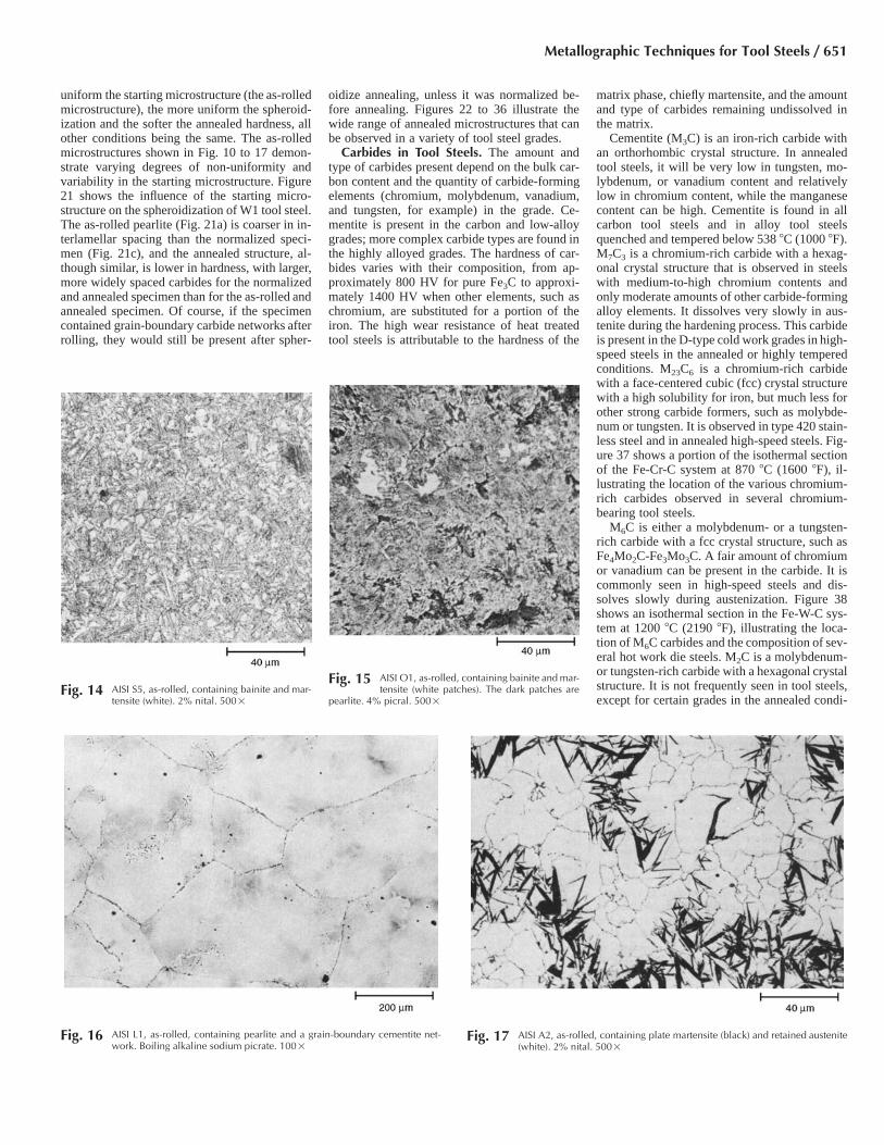
influence on the distribution and morphology ofcarbides after the subsequent spheroidize anneal.The micrographs in Fig. 10 to 17 illustrate thecomplex microstructures that are often presentin the as-hot-worked condition prior to annealingand the influence of this structure on the an-nealed microstructure. In general, the cooling af-ter hot working must be controlled to produce asuniform a carbon distribution as possible, so thatthe annealed carbide distribution does not vary.
Some tool steels, such as the 5% Cr hot workgrades and the 12% Cr plastic molding steels,tend to form carbide networks at the prior-aus-tenite grain boundaries present at the end of thehot working operation. Such networks can bedifficult to remove during annealing and can de-grade tensile ductility and toughness, even ifthey are semicontinuous. Figure 18 illustratesgrain-boundary carbide networks in type 420stainless steel used for plastic molding. The
high-carbon, water-hardening grades may de-velop grain-boundary carbide networks aftercooling from the hot rolling temperature, asshown in Fig. 19. Stringers of complex alloy car-bides may be observed in certain grades, andthese are often harmful. Figure 20 shows an ex-ample in H13 tool steel.
Annealed Microstructures. Because mosttool steels are relatively hard, even when an-nealed, it is usually necessary to control carbidemorphology during annealing to maximizemachinability and formability. For most toolsteels, a spheroidal carbide shape is the desiredcondition, although for a few of the low-alloytool steels, certain machining operations are im-proved when the structure is partially pearlitic.
Most tool steels and all high-alloy grades arespheroidize annealed at the mill. Control of an-
nealed microstructures is discussed in the article“Introduction to Heat Treating of Tool Steels” inHeat Treating, Volume 4 of Metals Handbook,9th ed. (1981). For a given grade, the hardnessdecreases as the degree of spheroidization in-creases. Once spheroidization has been obtained,growth of the carbides, which produces fewercarbides per unit volume and a greater apparentspacing, further reduces hardness. However, ifthe carbide structure is too coarse, dissolving therequired amount of carbon during austenitizationwill be more difficult. In addition, many toolsteels require a fine, uniform distribution of un-dissolved carbides to resist grain growth duringaustenitization.
Control of the spheroidization annealing pro-cess is important for good machinability andgood formability, such as in hobbing. The more
Fig. 9 AISI D2, quenched and tempered. Use of vapor-deposited zinc selenide to accentuate carbide
detection and retained austenite. Samples were etched firstwith 4% picral plus HCl (a) to outline the carbides, thencoated with a thin layer of zinc selenide (b) to reveal thecarbides (dark violet), retained austenite (white), and mar-tensite (dark). 1000�
Fig. 11 AISI L6, as-rolled, containing bainite and mar-tensite (white). 2% nital. 500�
Fig. 10 AISI W1 (1.3% C), as-rolled, containing pearl-ite and acicular cementite. 4% picral. 500�
Fig. 13 AISI S4, as-rolled, containing bainite and mar-tensite (featureless patches). This bar was
cooled at a faster rate after rolling than the one in Fig. 12.4% picral. 500�
Fig. 12 AISI S4, as-rolled, containing ferrite (white) andpearlite. 4% picral. 500�
650 / Metallography and Microstructures of Ferrous Alloys
uniform the starting microstructure (the as-rolledmicrostructure), the more uniform the spheroid-ization and the softer the annealed hardness, allother conditions being the same. The as-rolledmicrostructures shown in Fig. 10 to 17 demon-strate varying degrees of non-uniformity andvariability in the starting microstructure. Figure21 shows the influence of the starting micro-structure on the spheroidization of W1 tool steel.The as-rolled pearlite (Fig. 21a) is coarser in in-terlamellar spacing than the normalized speci-men (Fig. 21c), and the annealed structure, al-though similar, is lower in hardness, with larger,more widely spaced carbides for the normalizedand annealed specimen than for the as-rolled andannealed specimen. Of course, if the specimencontained grain-boundary carbide networks afterrolling, they would still be present after spher-
oidize annealing, unless it was normalized be-fore annealing. Figures 22 to 36 illustrate thewide range of annealed microstructures that canbe observed in a variety of tool steel grades.
Carbides in Tool Steels. The amount andtype of carbides present depend on the bulk car-bon content and the quantity of carbide-formingelements (chromium, molybdenum, vanadium,and tungsten, for example) in the grade. Ce-mentite is present in the carbon and low-alloygrades; more complex carbide types are found inthe highly alloyed grades. The hardness of car-bides varies with their composition, from ap-proximately 800 HV for pure Fe3C to approxi-mately 1400 HV when other elements, such aschromium, are substituted for a portion of theiron. The high wear resistance of heat treatedtool steels is attributable to the hardness of the
matrix phase, chiefly martensite, and the amountand type of carbides remaining undissolved inthe matrix.
Cementite (M3C) is an iron-rich carbide withan orthorhombic crystal structure. In annealedtool steels, it will be very low in tungsten, mo-lybdenum, or vanadium content and relativelylow in chromium content, while the manganesecontent can be high. Cementite is found in allcarbon tool steels and in alloy tool steelsquenched and tempered below 538 �C (1000 �F).M7C3 is a chromium-rich carbide with a hexag-onal crystal structure that is observed in steelswith medium-to-high chromium contents andonly moderate amounts of other carbide-formingalloy elements. It dissolves very slowly in aus-tenite during the hardening process. This carbideis present in the D-type cold work grades in high-speed steels in the annealed or highly temperedconditions. M23C6 is a chromium-rich carbidewith a face-centered cubic (fcc) crystal structurewith a high solubility for iron, but much less forother strong carbide formers, such as molybde-num or tungsten. It is observed in type 420 stain-less steel and in annealed high-speed steels. Fig-ure 37 shows a portion of the isothermal sectionof the Fe-Cr-C system at 870 �C (1600 �F), il-lustrating the location of the various chromium-rich carbides observed in several chromium-bearing tool steels.
M6C is either a molybdenum- or a tungsten-rich carbide with a fcc crystal structure, such asFe4Mo2C-Fe3Mo3C. A fair amount of chromiumor vanadium can be present in the carbide. It iscommonly seen in high-speed steels and dis-solves slowly during austenization. Figure 38shows an isothermal section in the Fe-W-C sys-tem at 1200 �C (2190 �F), illustrating the loca-tion of M6C carbides and the composition of sev-eral hot work die steels. M2C is a molybdenum-or tungsten-rich carbide with a hexagonal crystalstructure. It is not frequently seen in tool steels,except for certain grades in the annealed condi-
Fig. 14 AISI S5, as-rolled, containing bainite and mar-tensite (white). 2% nital. 500�
Fig. 15 AISI O1, as-rolled, containing bainite and mar-tensite (white patches). The dark patches are
pearlite. 4% picral. 500�
Fig. 16 AISI L1, as-rolled, containing pearlite and a grain-boundary cementite net-work. Boiling alkaline sodium picrate. 100�
Fig. 17 AISI A2, as-rolled, containing plate martensite (black) and retained austenite(white). 2% nital. 500�
Metallographic Techniques for Tool Steels / 651

tion. MC is most frequently a vanadium-rich car-bide with a fcc NaCl-type crystal structure. Otherstrong carbide-forming elements, such as tita-nium, niobium, tantalum, and zirconium, canform MC carbides, but these elements are notcommon in tool steels. MC is observed in steelswith moderate-to-high vanadium contents,chiefly high-speed tool steels. It has very strongbonds and is the hardest carbide. It resists dis-solution during austenization.
The amount of carbides present in tool steelsis greater in the annealed condition than afteraustenitizing and quenching, because the car-bides supply the austenite with the carbon nec-essary to achieve high hardness levels. The typeof carbides obtained also varies as a function ofcomposition. As an example, Fig. 39 shows thecomposition and amount of carbides observed indifferent high-speed steels in the annealed andin the hardened conditions.
Effect of Composition on Microstructure.Because tool steels are somewhat more difficultto machine than carbon and alloy steels, the com-positions of some grades are adjusted by increas-ing the silicon content to retain a certain amountof the carbon present as graphite. When viewedon a transverse plane (Fig. 40), the graphite ap-pears as small, globular particles, but they arenot nodular in shape as in ductile cast iron. Onthe longitudinal plane (Fig. 41), the graphite par-ticles are shown to be elongated, although theiraspect ratios are not excessively high. The mostcommonly used graphitic tool steel is AISI O6,which typically contains approximately 0.3 to0.5% of the total carbon content as graphite. Theamount of carbon as graphite must be controlledcarefully to ensure uniform hardening response.The presence of graphite improves machiningand wear characteristics.
Undesired graphitization can occur in high-carbon tool steels if those elements that promote
graphitization are not controlled. Processing pro-cedures can also affect graphitization; therefore,in carbon tool steels with more than approxi-mately 1.1% C, processing must also be care-fully controlled.
Sulfur is added to several tool steel grades toimprove machinability. Generally, the amount ofsulfur added to tool steels is less than that addedto free-machining carbon steels. Because man-ganese sulfide inclusions degrade toughness,certain tool steel grades are made with very lowsulfur contents, often less than 0.003%, for criti-cal applications. Although this practice enhancesmechanical properties, these tool steels can bemore difficult to machine.
Hobbing steels must be quite soft to permitoptimal cold workability and maximum life ofthe master hob. Such steels are very low in car-bon, although some medium-carbon alloygrades, such as AISI S5, are hobbed. The low-
carbon hobbing steels, such as AISI P2, must becarburized after hobbing and before hardening.These low-carbon grades are rather soft as-an-nealed and are designed to minimize work hard-ening during forming. Medium-carbon AISI S5must be very carefully spheroidize annealed toas low a hardness as possible to enhance hobb-ability. Achieving a low annealed hardness withthis grade is difficult, however, because its highsilicon content substantially strengthens the fer-rite.
Heat Treated Microstructures. Tool steelcompositions range from carbon tool steels withno alloy additions to high-speed steels contain-ing 20% or more alloying elements. Conse-quently, hardenabilities vary widely, producingquenching requirements that vary from brine toair. Each tool steel grade has been studied to de-termine the proper quench media, as a function
Fig. 18 Grain-boundary carbide networks in type 420 martensitic stainless steel (Fe-0.35%C-0.4%Mn-13%Cr) with two different etchants. (a) Vilella’s reagent. (b) Beraha’s sulfamicacid tint etch. Heat treatment: 1038 �C (1900 �F). Air quench: 177 �C (350 �F) temper. 500�
Fig. 20 Carbides in light-etching segregation band ofAISI H13 hot work die steel (Fe-0.40%C-
0.8%Si-5.25%Cr-1%V-1.35%Mo). 2% nital. 500�
Fig. 19 Grain-boundary carbide networks after coolingfrom the hot rolling temperature of high-car-
bon, water-hardening grade (Fe-1.31%C-0.35%Mn-0.25%Si, as-rolled). Alkaline sodium picrate etch: 90 �C(195 �F), 60 s. 500�
652 / Metallography and Microstructures of Ferrous Alloys

of section size, to permit hardening to marten-site. Although the carbon tool steels are usuallynot through hardened, most of the other gradesare. Another exception is the low-carbon hob-bing grades that are carburized and surface hard-ened. Figure 42 shows the surface of a poorlycarburized specimen of P5 tool steel with an ex-tensive intergranular carbide network and a car-bide film on the surface. This mold failed pre-maturely in service as a result. A few grades arealso nitrided or carbonitrided for special appli-cations. Figure 43 shows the microstructure ofgas nitrided H13 tool steel, while Fig. 44 showsan ion-nitrided H13 specimen. Note the (brittle)white-etching iron nitride layer at the extremesurface.
Most tool steels are hardened and tempered torather high hardnesses (generally, �58 HRC or
greater) to obtain good wear resistance. Excep-tions are the hot work tool steels that arequenched and tempered to hardnesses from ap-proximately 42 to 55 HRC and prehardened plas-tic molding steels, such as AISI P20, that aresold in the heat treated condition at approxi-mately 32 HRC. The prehardened tool steels aremachined and used in this condition without sub-sequent heat treatment except, perhaps, for astress-relief temper.
The correct austenitizing temperature for eachgrade has been determined experimentally by us-ing an austenitizing series. Samples are heatedto various temperatures and quenched at a rateconsistent with the anticipated hardenability.Each as-quenched sample is fractured to rate theprior-austenite grain size by the Shepherd com-parison method. Next, the samples are carefully
ground on one of the fracture faces and testedfor hardness. As the austenitizing temperatureincreases, hardness will increase, level off, thendecrease. The fracture grain size will remainrelatively constant, usually up to the austenitiz-ing temperature where the as-quenched hardnesslevels out, then will decrease due to graingrowth. The optimal austenitizing temperature isthat temperature or range where the hardness ishighest and the grain size is finest. Dilatometryis generally conducted before such tests to es-tablish the optimal temperature range.
To illustrate the effect of varying the austeni-tizing temperature on the microstructure of toolsteels, it is necessary to examine grades withvarying carbon content and carbide types. Figure45 shows the microstructure of air-hardened S7tool steel with a carbon content of approximately
Fig. 21 AISI W1 (1.05% C). Influence of starting structure on spheroidization. (a) As-rolled; contains coarse and fine pearlite. (b) After spheroidization (heat to 760 �C, or 1400 �F;cool at a rate of 11 �C/h, or 20 �F/h, to 595 �C, or 1100 �F; air cool). (c) Austenitized at 870 �C (1600 �F) and oil quenched to produce fine pearlite. (d) Austenitized as in
(c); annealed as in (b). Note the more uniform spherical carbide shape compared to (b). 4% picral. 500�
Fig. 22 AISI W4 water-hardening tool steel (0.98C-0.74Mn-0.14Cr-0.19Ni), as-received (mill an-
nealed). 187 HB. Spheroidal cementite in a matrix of fer-rite; a considerable amount of lamellar pearlite is alsopresent. 4% picral. 1000�
Fig. 23 AISI W4 water-hardening tool steel (0.96C-0.66Mn-0.23Cr), as-received (full annealed).
170 HB. Structure consists of spheroidal cementite in a fer-rite matrix; no lamellar constituent is present. Comparewith Fig. 22. 4% picral. 1000�
Fig. 24 AISI W1 water-hardening tool steel (0.94C-0.21Mn), as-received (mill annealed). 170 HB.
Structure: mixture of lamellar pearlite and spheroidal ce-mentite in a matrix of ferrite, with a few large, globularcarbide particles. 3% nital. 1000�
Metallographic Techniques for Tool Steels / 653

0.5%. The preferred austenitizing temperaturefor S7 is 940 �C (1725 �F), and the grade is rathersensitive to under- and overaustenitization. Un-deraustenitization does not dissolve enough car-bide to get full hardness. Overaustenitization re-sults in grain growth, because all of the carbideis put in solution and it is not aluminum-killed,so there is no AlN to inhibit grain growth. Figure46 shows the microstructure of O1 tool steel, anoil-hardening grade with approximately 0.9% C.The preferred austenitizing temperature is 800�C (1475 �F), so this series compares the correctquenched microstructure to overaustenitized mi-crostructures. It demonstrates how increasing thecarbon content of the austenite depresses themartensite start temperature, resulting in increas-
ing retained austenite. A more dramatic effect onthe microstructure is observed when a high-car-bon, high-alloy tool steel, such as type D2, isexamined in the overaustenitized condition. Fig-ure 47 shows D2 after air quenching from vari-ous temperatures, from 1010 to 1230 �C (1850to 2250 �F). The recommended austenitizingtemperature is 1010 �C (1850 �F). Note that re-tained austenite, which is present even at the cor-rect austenitizing temperature, cannot be ob-served by light microscopy until a substantialamount is present; certainly, more than 10% isrequired before it can be seen.
Carbon tool steels are hypereutectoid and con-tain only cementite, which is easily dissolved.The iron-carbon equilibrium diagram is a good
starting point for establishing the correct austen-itizing temperature. For these steels, maximumhardness results when approximately 0.60 to0.65% C is put into solution. Therefore, the as-quenched structure will consist of martensite andresidual cementite, that is, the carbides not putinto solution. A small amount of retained aus-tenite will also be present, but it will not be de-tectable with a light microscope if the properaustenitizing temperature is used. Figure 48shows the microstructure of W1 tool steel in thehardened case, the transition zone, and the un-hardened core after brine quenching a 19 mm(0.75 in.) diameter bar. The case is high-carbonmartensite, and the core is very fine pearlite. Notall of the cementite should be put into solution,
Fig. 25 AISI L1, spheroidize annealed. Note the very-well-formed spheroidal carbides. 4% picral.
500�Fig. 26 AISI S2, spheroidize annealed. 4% picral.
1000�Fig. 27 AISI S5, spheroidize annealed. 4% picral.
500�
Fig. 28 AISI S7, spheroidize annealed. 4% picral.1000�
Fig. 29 AISI A6, spheroidize annealed. 4% picral.1000�
Fig. 30 AISI A6, partially spheroidized. Note lamellarpearlite. 4% picral. 1000�
654 / Metallography and Microstructures of Ferrous Alloys

so residual cementite should be present at all lo-cations. Quenched and tempered microstructuresof a variety of other low-alloy grades with me-dium levels of carbon are shown in Fig. 49 to54, while the microstructure of higher-alloy toolsteels are shown in Fig. 55 to 66.
If a sufficiently high austenitizing temperatureis used, the carbon content of the austenite willbe raised to such an extent that the martensitefinish temperature is well below room tempera-ture. Because retained austenite is relatively softcompared to martensite, the bulk hardness willbe lower. The microstructure will exhibit coarseplate (acicular) martensite and retained austenite.As the austenitizing temperature exceeds the op-timal temperature, the amount of residual ce-mentite decreases, the amount of retained aus-tenite increases, the hardness decreases, and thegrain size increases.
In general, if the amount of retained austeniteis high enough to be observed with a light mi-croscope, the steel has been overaustenitized.Tempering will not convert high levels of re-tained austenite to martensite or bainite unlessthe tempering temperature is rather high. More-over, the retained austenite will not be stableenough to withstand shock-induced transforma-tion to martensite during service. When suchtransformation occurs, the high-hardness matrixlacks enough ductility to accommodate the trans-formation stresses, and cracking results.
Low heat treated hardnesses may also result ifthe section size and quench rate are selected in-correctly for a particular grade. When the har-denability is inadequate to permit full hardening,pearlite or bainite will be observed in the micro-structure. Ferrite may also be visible in the fewtool steels that are hypoeutectoid, although this
is less common. Brine- and water-quenchinggrades are also susceptible to formation of softspots within the case, caused by localized slowcooling from tongs holding the sample or by in-adequate agitation (failure to break up vaporpockets due to localized boiling of the quenchmedia).
After quenching, tool steels must be immedi-ately tempered to reduce the very high transfor-mation stresses, or quench cracking may occur.Quench cracking is more likely to occur as thequench rate increases and if the geometry of thespecimen exhibits stress raisers. Air-hardenablesteels are less susceptible to quench cracking,because the slow rate of cooling helps to relievesome of the transformation stresses.
Many tool steels are often tempered at 175 to230 �C (350 to 450 �F). These low temperingtemperatures do little to the structure except re-
Fig. 31 AISI H13 chromium hot-worked tool steel,spheroidize annealed. 4% picral. 1000�
Fig. 32 AISI M2 molybdenum high-speed tool steel,spheroidize annealed. 4% picral. 1000�
Fig. 33 AISI A7 tool steel, box annealed at 900 �C(1650 �F) for 1 h per 25 mm (1.0 in.) of con-
tainer thickness and cooled at no more than 28 �C/h (50�F/h). Massive alloy carbide and spheroidal carbide in aferrite matrix. 4% nital. 1000�
Fig. 34 AISI A10 tool steel, as-received (mill annealed).Section transverse to rolling direction. At the
magnification used, the structure is poorly resolved. Nital.100�
Fig. 35 AISI H23 tool steel, annealed by austenitizingat 870 �C (1600 �F) for 2 h and cooling at 28
�C/h (50 �F/h) to 540 �C (1000 �F), then air cooling. 98 HRB.Structure consists of tiny spheroidal and some larger alloycarbide particles in a matrix of ferrite. Kalling’s reagent.500�
Fig. 36 AISI H26 tool steel, annealed by austenitizingat 900 �C (1650 �F), cooling at 8.5 �C/h (15 �F/
h) to 650 �C (1200 �F), then air cooling. 22 to 23 HRC.Structure consists of a dispersion of fine particles of alloycarbide in a matrix of ferrite. Picral with HCl, 10 s. 500�
Metallographic Techniques for Tool Steels / 655

Fig. 37 Portion of the 870 �C (1600 �F) isothermal section of the Fe-Cr-C system with approximate compositions ofAISI H13, A2, D2, and type 420 steels indicated. Source: Ref 7
Fig. 38 Isothermal section of Fe-W-C diagram at 1200�C (2190 �F). Nominal compositions of tung-
sten, carbon, and iron for some tungsten hot work steelsare plotted. Source: Ref 8
Fig. 40 AISI O6, spheroidize annealed, transverse sec-tion. Note the globular appearance of the
graphite (black). 4% picral. 500�
Fig. 39 Carbides in various high-speed steels, both in annealed conditions and after being heated to normal austen-itizing temperatures. Open bars represent quantities in annealed steels. Solid bars indicate amounts after
austenitizing at hardening temperatures indicated.
lieve quenching stresses. Hot work and high-speed steels are usually tempered at relativelyhigh temperatures. Due to their high alloy con-
tent, these grades can resist softening duringtempering to rather high levels. These higher-alloy steels are often tempered hot enough to
cause secondary hardening and to change the na-ture of the carbides present. These changes, how-ever, can be detected only by methods more so-phisticated than light microscopy. In general, thelowest-alloy tool steels receive a single temper,typically 2 h for every 25 mm (1 in.) of thick-ness. Higher-alloy tool steels are usually tem-pered twice; high-speed steels may be temperedthree times. Double and triple tempering is re-quired to condition and stabilize the microstruc-ture.
When a substantial amount of strong carbide-forming elements are present, tempering at hightemperatures, where secondary hardening oc-curs, results in a change in carbide compositionand type. To illustrate this, Fig. 67 shows theeffect of time and temperature on the type ofcarbide present in a 12% Cr martensitic steel,more highly alloyed than type 420. At low tem-pering temperatures, M3C will be present. How-ever, with higher temperatures and longer times,M3C is replaced by M7C3 and M23C6, only thelatter being present at still higher temperaturesand longer times. This steel contained a some-what high nitrogen content, and M2N nitrides
656 / Metallography and Microstructures of Ferrous Alloys

were observed as well. Figure 68 shows the se-quence of carbide formation in two tungsten-type high-speed steels as a function of temperingtemperature. Both exhibit strong secondaryhardening at approximately 600 �C (1110 �F).
For many tool steels, tempering to approxi-mately 540 �C (1000 �F) produces only subtledifferences in the microstructure viewed opti-cally, as shown in Fig. 69. The speed at whichetching occurs and the darkness of the matrixwill change with tempering. Tempering just be-low the lower critical temperature is required toproduce pronounced microstructural changes,but such high tempers have no practical appli-cations for tools and dies, except as an anneal.
Heat treated tool steel microstructures aresimilar in appearance when the grades are prop-erly heat treated. The primary differences are theamount and type of the residual, undissolved car-bides that will influence the coarseness of theplate martensite. In many tool steels, the marten-site phase is so fine that little detail is observed.This is not the case for grades that exhibit verylittle residual carbides, for example, AISI S1, S5,and S7. These shock-resisting tool steels havelower carbon contents, and nearly all of the car-bon is dissolved in the austenite. Consequently,the martensite is coarser, with more detail ob-servable by light microscopy.
In some cases, quenching does not produce afully martensitic structure. This occurs mainlywhen the hardenability is inadequate forthrough hardening for the section size andquench medium chosen. The continuous cool-ing transformation (CCT) diagram is a goodtool for the metallurgist when evaluating heattreatment problems. Unfortunately, diagrams donot exist for all standard grades. Figure 70shows a CCT diagram for S7 tool steel. Figures71 and 72 illustrate the microstructural varia-tions in S7 produced by varying the quench ratefrom 2780 to 28 �C/h (5000 to 50 �F/h). Iso-thermal transformation (IT) diagrams (alsocalled time-temperature-transformation or S-curves) have often been used when diagnosingheat treatment problems, but they cannot beused with most tool steels, because the trans-formations depicted by the IT diagram are muchdifferent than those shown in the correspondingCCT diagram. As an example, compare theCCT diagram for S7 shown in Fig. 70 with theIT diagram for S7 shown in Fig. 73. There issome similarity here, but with higher-alloyedtool steels, the similarity is less. The IT dia-grams are very useful for developing annealingcycles and for isothermal treatments such asausforming. Figure 74 shows the microstructureof S7 held at 704 �C (1300 �F) for 30 min (onlya small amount of transformation beforequenching) and for 4 h (almost complete trans-formation to pearlite). A wide range of isoth-ermally formed microstructures is shown in Fig.75 to 78 for S5 tool steel.
Powder Metallurgy Products. Highly al-loyed grades, such as the high-speed steels, aredifficult to manufacture by ingot-making tech-nology, because they are plagued by alloy and
carbide segregation and poor ingot-to-finishedproduct yields. Consequently, the powder met-allurgy process now makes many of these gradesroutinely. Indeed, there are some grades thathave been developed that can only be made bypowder metallurgy, and these grades exhibit out-standing resistance to the high temperatures ex-perienced by cutting tools. Figures 79 to 82 il-lustrate T15 high-speed steel made by powdermetallurgy, showing the microstructure after hotisostatic pressing, after it was spheroidize an-nealed, and after it was hardened. The carbidesare fine and evenly distributed, without any ap-parent segregation.
Compositions for the tool steels illustrated inthis article are listed in Table 5. Information on
properties, tempers, designations, and applica-tions of tool steels can be found in the articles“Wrought Tool Steels” and “P/M Tool Steels” inProperties and Selection: Irons, Steels, andHigh-Performance Alloys, Volume 1 of ASMHandbook (1990) and in Ref 11.
Fig. 41 AISI O6, spheroidize annealed, longitudinalsection. Note that the graphite is elongated in
the rolling direction. 4% picral. 500�
Fig. 42 Poorly carburized AISI P5 plastic-mold toolsteel with an extensive intergranular carbide
network and a carbide film on the surface. Three steps witha pressed synthetic chemical-textile pad; 10 min on step 3.Nital. 200�
Fig. 43 Gas nitrided AISI H13 tool steel. Four steps with a rigid grinding disk. Nital. (a) 200�. (b) 1000�
Metallographic Techniques for Tool Steels / 657

Fig. 44 Ion nitrided AISI H13 tool steel with a brittle white-etching iron nitride layer at the extreme surface. (a) Mounted with silica-filled epoxy. (b) Nickel plated and mountedwith silica-filled epoxy. Vilella’s reagent. Note that in (b) the iron nitride layer may be easily missed due to the similar color of it on the plating. 1000�
Fig. 45 AISI S7 (0.5% C). Influence of austenitizing temperature. (a) Austenitized at 915 �C (1675 �F) 1 h for every 25 mm (1.0 in.) of thickness and air quenched. Sample isunderaustenitized. (b) Austenitized at 925 �C (1700 �F). Slightly underaustenitized. (c) Austenitized at the preferred temperature of 940 �C (1725 �F). (d) Austenitized at 955
�C (1750 �F). Slightly overaustenitized; note coarsening, no visible carbide. 4% picral. 500�
Fig. 46 AISI O1. Influence of austenitizing temperature on microstructure. (a) Austenitized at 800 �C (1475 �F) 1 h for every 25 mm (1.0 in.) of thickness. 65 HRC, grain size 9.5.Specimen properly austenitized. (b) Austenitized at 870 �C (1600 �F). 65 HRC, grain size 9. Overaustenitized. (c) Austenitized at 980 �C (1800 �F). 64 HRC, grain size 7.
Very overaustenitized; all carbide dissolved. (d) Austenitized at 1100 �C (2010 �F). 64 HRC, grain size 3. Severely overaustenitized; note retained austenite (white). 4% picral. 500�
658 / Metallography and Microstructures of Ferrous Alloys

Metallographic Techniques for Tool Steels / 659
Fig. 47 AISI D2 tool steel microstructure (Vilella’s etch, 1000�) after air quenching from various austenitizing tem-peratures. Note that retained austenite, which is present even at the correct austenitizing temperature (1010
�C, or 1850 �F), cannot be observed by light microscopy until a substantial amount is present. (a) 1010 �C (1850 �F) airquenched. (b) 1065 �C (1950 �F) air quenched. (c) 1120 �C (2050 �F) air quenched. (d) 1175 �C (2150 �F) air quenched.(e) 1230 �C (2250 �F) air quenched
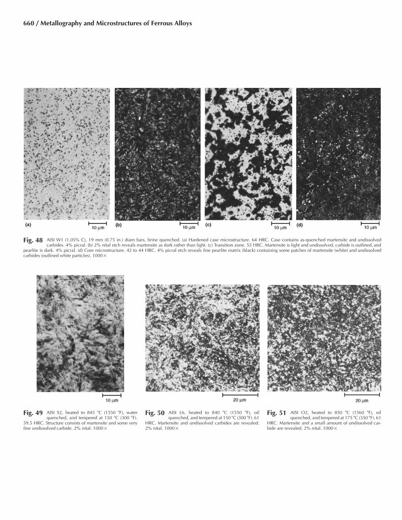
Fig. 48 AISI W1 (1.05% C), 19 mm (0.75 in.) diam bars, brine quenched. (a) Hardened case microstructure. 64 HRC. Case contains as-quenched martensite and undissolvedcarbides. 4% picral. (b) 2% nital etch reveals martensite as dark rather than light. (c) Transition zone. 55 HRC. Martensite is light and undissolved, carbide is outlined, and
pearlite is dark. 4% picral. (d) Core microstructure. 42 to 44 HRC. 4% picral etch reveals fine pearlite matrix (black) containing some patches of martensite (white) and undissolvedcarbides (outlined white particles). 1000�
Fig. 49 AISI S2, heated to 845 �C (1550 �F), waterquenched, and tempered at 150 �C (300 �F).
59.5 HRC. Structure consists of martensite and some veryfine undissolved carbide. 2% nital. 1000�
Fig. 50 AISI L6, heated to 840 �C (1550 �F), oilquenched, and tempered at 150 �C (300 �F). 61
HRC. Martensite and undissolved carbides are revealed.2% nital. 1000�
Fig. 51 AISI O2, heated to 850 �C (1560 �F), oilquenched, and tempered at 175 �C (350 �F). 61
HRC. Martensite and a small amount of undissolved car-bide are revealed. 2% nital. 1000�
660 / Metallography and Microstructures of Ferrous Alloys
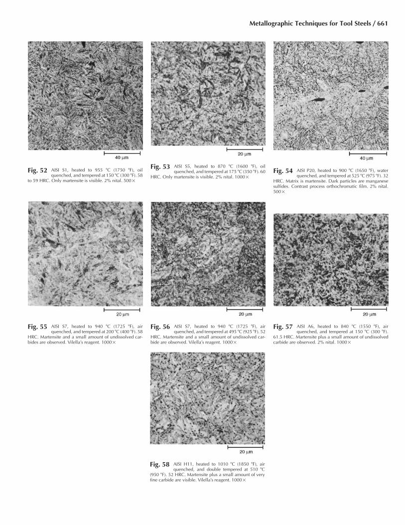
Fig. 52 AISI S1, heated to 955 �C (1750 �F), oilquenched, and tempered at 150 �C (300 �F). 58
to 59 HRC. Only martensite is visible. 2% nital. 500�
Fig. 53 AISI S5, heated to 870 �C (1600 �F), oilquenched, and tempered at 175 �C (350 �F). 60
HRC. Only martensite is visible. 2% nital. 1000�Fig. 54 AISI P20, heated to 900 �C (1650 �F), water
quenched, and tempered at 525 �C (975 �F). 32HRC. Matrix is martensite. Dark particles are manganesesulfides. Contrast process orthochromatic film. 2% nital.500�
Fig. 55 AISI S7, heated to 940 �C (1725 �F), airquenched, and tempered at 200 �C (400 �F). 58
HRC. Martensite and a small amount of undissolved car-bides are observed. Vilella’s reagent. 1000�
Fig. 56 AISI S7, heated to 940 �C (1725 �F), airquenched, and tempered at 495 �C (925 �F). 52
HRC. Martensite and a small amount of undissolved car-bide are observed. Vilella’s reagent. 1000�
Fig. 57 AISI A6, heated to 840 �C (1550 �F), airquenched, and tempered at 150 �C (300 �F).
61.5 HRC. Martensite plus a small amount of undissolvedcarbide are observed. 2% nital. 1000�
Fig. 58 AISI H11, heated to 1010 �C (1850 �F), airquenched, and double tempered at 510 �C
(950 �F). 52 HRC. Martensite plus a small amount of veryfine carbide are visible. Vilella’s reagent. 1000�
Metallographic Techniques for Tool Steels / 661
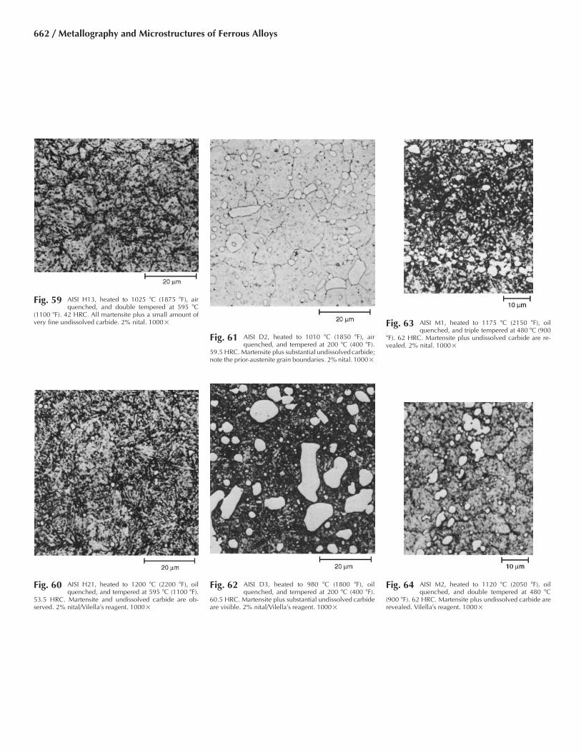
Fig. 59 AISI H13, heated to 1025 �C (1875 �F), airquenched, and double tempered at 595 �C
(1100 �F). 42 HRC. All martensite plus a small amount ofvery fine undissolved carbide. 2% nital. 1000�
Fig. 60 AISI H21, heated to 1200 �C (2200 �F), oilquenched, and tempered at 595 �C (1100 �F).
53.5 HRC. Martensite and undissolved carbide are ob-served. 2% nital/Vilella’s reagent. 1000�
Fig. 61 AISI D2, heated to 1010 �C (1850 �F), airquenched, and tempered at 200 �C (400 �F).
59.5 HRC. Martensite plus substantial undissolvedcarbide;note the prior-austenite grain boundaries. 2% nital. 1000�
Fig. 62 AISI D3, heated to 980 �C (1800 �F), oilquenched, and tempered at 200 �C (400 �F).
60.5 HRC. Martensite plus substantial undissolved carbideare visible. 2% nital/Vilella’s reagent. 1000�
Fig. 63 AISI M1, heated to 1175 �C (2150 �F), oilquenched, and triple tempered at 480 �C (900
�F). 62 HRC. Martensite plus undissolved carbide are re-vealed. 2% nital. 1000�
Fig. 64 AISI M2, heated to 1120 �C (2050 �F), oilquenched, and double tempered at 480 �C
(900 �F). 62 HRC. Martensite plus undissolved carbide arerevealed. Vilella’s reagent. 1000�
662 / Metallography and Microstructures of Ferrous Alloys

Fig. 65 AISI M4, heated to 1220 �C (2225 �F), oilquenched, and double tempered at 480 �C
(900 �F). 62 HRC. Martensite plus undissolved carbide arerevealed. Vilella’s reagent. 1000�
Fig. 66 AISI M42, heated to 1175 �C (2150 �F), oilquenched, and triple tempered at 565 �C (1050
�F). 65 HRC. Martensite plus undissolved carbide are ob-served. Vilella’s reagent. 1000�
Fig. 67 Time-temperature diagram of carbides presentin two 12% Cr martensitic stainless steels after
tempering. Solid lines (for alloy A) and broken lines (foralloy B) show when fine precipitates are first observed. Al-loy A composition: 0.21% C, 13.2% Cr, and 0.24% N. Al-loy B composition: 0.18% C, 0.58% Mn, 0.31% Si, 0.18%Ni, 11.7% Cr, 0.49% Mo, 0.01% Al, 0.38% V, 0.20% Nb,and 0.033% N. This diagram is based on observations ofspecimens subjected to more than 30 different temperingtreatments in the temperature interval of 500 to 700 �C (930to 1290 �F). Source: Ref 9
Fig. 68 Sequence of alloy carbide formation in twotungsten-type high-speed steels as a function of
tempering temperature. Steel A contains 0.8% C, 18% W,4% Cr, 2% V, and 10% Co; steel B contains 0.8% C, 9%W, 3% Cr, and 3% Co. Source: Ref 10
Metallographic Techniques for Tool Steels / 663
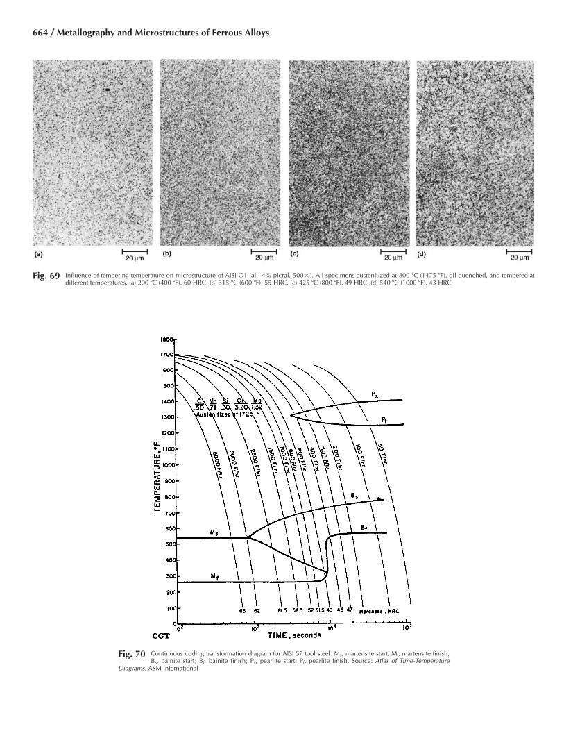
Fig. 69 Influence of tempering temperature on microstructure of AISI O1 (all: 4% picral, 500�). All specimens austenitized at 800 �C (1475 �F), oil quenched, and tempered atdifferent temperatures. (a) 200 �C (400 �F). 60 HRC. (b) 315 �C (600 �F). 55 HRC. (c) 425 �C (800 �F). 49 HRC. (d) 540 �C (1000 �F). 43 HRC
Fig. 70 Continuous coding transformation diagram for AISI S7 tool steel. Ms, martensite start; Mf, martensite finish;Bs, bainite start; Bf, bainite finish; Ps, pearlite start; Pf, pearlite finish. Source: Atlas of Time-Temperature
Diagrams, ASM International
664 / Metallography and Microstructures of Ferrous Alloys

Fig. 71 AISI S7 continuous cooling transformations. Some very fine undissolved carbide is present in all specimens in this series. (a) Austenitized at 940 �C (1725 �F) and cooled at2780 �C/h (5000 �F/h). 62 HRC. Structure is martensite plus a small amount of bainite. (b) Cooled at 1390 �C/h (2500 �F/h) to produce a greater amount of bainite. 61.5
HRC. (c) Cooled at 830 �C/h (1500 �F/h). 56.5 HRC. Structure is mostly bainite plus some martensite (light). 4% picral. 500�
Fig. 72 AISI S7 continuous cooling transformations. Some very fine carbide is present in all specimens in this series. (a) Austenitized at 940 �C (1725 �F) and cooled at 445 �C/h(800 �F/h). 51.5 HRC. Structure is nearly all bainite with some small patches of martensite (white). (b) Cooled at 220 �C/h (400 �F/h). 45 HRC. Structure is mostly bainite
with fine pearlite at the prior-austenite grain boundaries. (c) Cooled at 28 �C/h (50 �F/h) to 620 �C (1150 �F), then water quenched. Austenite present at 620 �C (1150 �F) was transformedto martensite. Structure is mostly fine pearlite with patches of martensite (white). See also Fig. 71. 4% picral. 500�
Metallographic Techniques for Tool Steels / 665

Fig. 73 Isothermal transformation diagram for AISI S7 tool steel. Composition: 0.50% C, 0.71% Mn, 0.30% Si, 3.20%Cr, and 1.32% Mo. Austenitized at 940 �C (1725 �F). Ms, martensite start; Bs bainite start; Bf, bainite finish; Ps,
pearlite start; Pf, pearlite finish. Source: Atlas of Time-Temperature Diagrams, ASM International
Fig. 74 Microstructure (picral etch, 500�) of AISI S7 tool steels with isothermal heat treatments. (a) Held at 704 �C (1300 �F) for 30 min (only a small amount of transformationbefore quenching). (b) Held at 704 �C (1300 �F) for 4 h (almost complete transformation to pearlite)
666 / Metallography and Microstructures of Ferrous Alloys

Fig. 75 AISI S5 austenitized and isothermally trans-formed at 650 �C (1200 �F) for 4 h (air cooled)
to form ferrite and coarse pearlite. 23 to 24 HRC. 4% picral.1000�
Fig. 76 AISI S5 austenitized, isothermally transformedat 595 �C (1100 �F) for 8 h, and air cooled to
form ferrite and fine pearlite. 36 HRC. 4% picral. 1000�
Fig. 77 AISI S5 austenitized, isothermally transformed(partially) at 540 �C (1000 �F) for 8 h, and water
quenched to form upper bainite (dark); balance of austeniteformed martensite. 4% picral/2% nital. 1000�
Fig. 78 AISI S5 austenitized, isothermally transformedat 400 �C (750 �F) for 1 h, and air cooled to
form lower bainite. 37 to 38 HRC. 4% picral/2% nital.1000�
Fig. 79 AISI T15, powder-made. Sample was slowcooled after hot isostatic pressing. 28 HRC.
Structure is partially annealed. 3% nital. 1000�
Fig. 80 AISI T15, powder-made. Sample was hot isos-tatically pressed, forged, and annealed. 24
HRC. Structure is fully annealed. 3% nital. 1000�
Metallographic Techniques for Tool Steels / 667

Fig. 81 AISI T15, powder-made. Processed as in Fig.80, then hardened; heated to 1230 �C (2250 �F)
for 5 min in salt, oil quenched, triple tempered 2 h each at540 �C (1000 �F). 65 HRC. 3% nital. 1000�
Fig. 82 AISI T15, powder-made. Same sample as inFig. 81 but etched in 100 mL H2O, 1 mL HCl,
1 g K2S2O5, and 1 g NH4•HF. 1000�
Table 5 Nominal compositions of illustrated tool steel grades
AISItype
Composition, %
C Mn(a) Si(b) Cr Ni V W Mo Co Ti
W1 0.6–1.4 . . . . . . . . . . . . 0.25 . . . . . . . . . . . .W2 0.6–1.4 . . . . . . . . . . . . . . . . . . . . . . . . . . .S1 0.5 . . . 0.75 1.5 . . . 0.2(c) 2.5 . . . . . . . . .S2 0.5 0.4 1.0 . . . . . . . . . . . . 0.5 . . . . . .S4 0.55 0.8 2.0 . . . . . . . . . . . . . . . . . . . . .S5 0.55 0.8 1.9 0.25(c) . . . 0.2(c) . . . 0.4 . . . . . .S7 0.5 0.7 . . . 3.25 . . . . . . . . . 1.40 . . . . . .O1 0.9 1.0 . . . 0.5 . . . 0.2(c) 0.5 . . . . . . . . .O2 0.9 1.6 . . . . . . . . . . . . . . . . . . . . . . . .O6 1.45 0.8 1.1 . . . . . . . . . . . . 0.25 . . . . . .A2 1.0 0.7 . . . 5.25 . . . 0.2(c) . . . 1.1 . . . . . .A6 0.7 2.0 . . . 1.0 . . . . . . . . . 1.35 . . . . . .A7 2.00–2.85 0.8 0.5 5.0–5.75 0.3 3.9–5.15 0.5–1.5 0.90–1.40 . . . . . .A10 1.25–1.50 1.6–2.1 1.0–1.5 . . . 1.55–2.05 . . . . . . 1.25–1.75 . . . . . .D2 1.5 0.5 . . . 12.0 . . . 0.2–0.9(c) . . . 0.8 . . . . . .D3 2.1 . . . . . . 12.0 0.5(c) . . . . . . . . . . . . . . .H11 0.35 . . . 0.9 5.0 . . . 0.4 . . . 1.5 . . . . . .H13 0.35 . . . 1.0 5.25 . . . 1.0 . . . 1.3 . . . . . .H21 0.35 . . . . . . 3.5 . . . 0.4(c) 9.0 . . . . . . . . .H23 0.25–0.35 0.15–0.40 0.15–0.60 11.0–12.75 0.3 0.75–1.25 11.0–12.75 . . . . . . . . .H26 0.45–0.55 0.15–0.40 0.15–0.40 3.75–4.5 0.3 0.75–1.25 17.25–19.0 . . . . . . . . .T1 0.7 . . . . . . 4.0 . . . 1.0 18.0 . . . . . . . . .T15 1.5 . . . . . . 4.0 . . . 5.0 12.0 . . . 5.0 . . .M1 0.8 . . . . . . 4.0 . . . 1.1 1.5 8.5 . . . . . .M2 0.85 . . . . . . 4.0 . . . 2.0 6.0 5.0 . . . . . .M4 1.3 . . . . . . 4.5 . . . 4.0 5.5 4.5 . . . . . .M42 1.1 . . . . . . 3.75 . . . 1.15 1.5 9.5 8.0 . . .L1 1.0 . . . . . . 1.4 . . . . . . . . . . . . . . . . . .L6 0.75 0.75 . . . 0.9 1.75 . . . . . . 0.35 . . . . . .F2 1.25 0.75 . . . . . . . . . . . . 0.35 . . . . . . . . .P5 0.1 . . . . . . 2.25 . . . . . . . . . . . . . . . . . .P20 0.35 . . . . . . 1.25 . . . . . . . . . 0.4 . . . . . .AHT 1.0 . . . . . . 3.0 . . . 0.25 1.05 1.1 . . . 1.0
(a) All tool steels contain some manganese, generally 0.2–0.4% when not listed. (b) Tool steels usually contain 0.2–0.35% Si unless listed otherwise.(c) Optional addition at discretion of manufacturer
668 / Metallography and Microstructures of Ferrous Alloys

REFERENCES
1. “Recommended Practice for MacroetchTesting of Tool Steel Bars,” A 561, AnnualBook of ASTM Standards, Vol 01.05,ASTM, 2003, p 335–341
2. “Macroetch Testing of Consumable Elec-trode Remelted Steel Bars and Billets,” A604, Annual Book of ASTM Standards, Vol01.05, ASTM, 2003, p 371–384
3. “Standard Method of Macroetch TestingSteel Bars, Billets, Blooms and Forgings,”E 381, Annual Book of ASTM Standards,Vol 03.01, ASTM, 1984, p 895–899
4. “Macrograph Standards for Steel Bars, Bil-lets and Blooms,” MIL-STD 430A, Depart-ment of Defense, 30 June 1966
5. G.F. Vander Voort, Metallography: Princi-ples and Practice, McGraw-Hill, 1984; re-printed by ASM International, 1999
6. “Standard Practice for Preparing SulfurPrints for Macrostructural Examination,” E1180, Annual Book of ASTM Standards, Vol01.03, ASTM, 2003, p 787–789
7. L.R. Woodyatt and G. Krauss, Iron-Chro-mium-Carbon System at 870 �C, Metall.Trans. A, Vol 7, 1976, p 983–989
8. S. Takeda, Metallographic Investigation ofthe Ternary Alloys of the Iron-Tungsten-Carbon System, Tech. Rep. Sendai, Vol 9,1930, p 483; Vol 10, 1931, p 42
9. A. Hede and B. Aronsson, Microstructureand Creep Properties of Some 12% Chro-mium Martensitic Steels, J. Iron Steel Inst.,Vol 207, Sept 1969, p 124
10. H.W. Rayson, Tool Steels, Constitution andProperties of Steels, F.B. Pickering, Ed.,VCH Publishing, 1992, p 581–640
11. G. Roberts, G. Krauss, and R. Kennedy, ToolSteels, 5th ed., ASM International, 1998
Metallographic Techniques for Tool Steels / 669