metallic part fabrication using selective inhibition ...yongchen/research/sis-metal-rpj.pdf · 1...
TRANSCRIPT

1
Metallic Part Fabrication Using Selective Inhibition Sintering (SIS)
Behrokh Khoshnevis, Mahdi Yoozbashizadeh, Yong Chen
Daniel J. Epstein Department of Industrial and Systems Engineering University of Southern California Los Angeles, CA 90089, U.S.A.
Abstract
The purpose of this research is to investigate the fundamentals of the Selective Inhibition Sintering (SIS)
process for th e fabrication of metallic parts. A SIS-Metal process has been developed based on the
microscopic mechanical inhibition principle. In this process metal salt solution is printed in the selected areas of
each metal powder layer; the salt re-crystallizes when water evaporates; salt crystals decompose and grow
rapidly prior to sintering; during the sintering process the constituents of decomposed salt particles spread
between metal powder particles and prevent the fusing of these particles together; consequently, the sintering
process in the affected regions is inhibited. This paper presents the research result on the inhibition mechanism
and process control of the SIS process. Experimental results are also presented to demonstrate the capability of
the process in fabricating metal parts with various geometries. The SIS-Metal process has numerous advantages
including low cost, minimal shrinkage and deformation effects, and independence from polymeric binders.
Originality/value: The paper illustrates a new additive manufacturing technology for metallic parts fabrication.
Keywords: Metallic parts fabrication, Powder sintering, Selective inhibition, Powder metallurgy
Paper type: Research Paper
1. Introduction
The Selective Inhibition Sintering (SIS) process is an additive manufacturing (AM) technology which
builds parts on a layer-by-layer basis. The principle idea of the SIS process is the prevention of selected
segments of each powder layer from sintering. Therefore, the SIS process may be considered as an opposite
approach to the Selective Laser Sintering (SLS) process in which selected areas of powder are sintered by a fine
laser beam. In previous work on the SIS for polymer powder [Khoshnevis et al, 2003; Asiabanpour et al., 2004;
Asiabanpour et al., 2006] it was demonstrated that the SIS-Polymer process can fabricate high quality parts at a
high speed using relatively low cost machines. In the research reported here the application of SIS to metal
powder (denoted as SIS-Metal) is investigated. Due to the high temperature and oxygen-free environment

2
required in the sintering of metallic powders (e.g. 800-1300°C) the previously developed SIS-Polymer process
in which each layer is sintered on the fabrication machine is not applicable to SIS-Metal. Hence, the SIS-Metal
process requires a dedicated effort for identifying a new inhibition mechanism by considering the sintering
properties of metal powder and a new sintering method, preferably using conventional sintering furnace. The
experimental results have demonstrated that the SIS-Metal concept is feasible and that commercial quality
metallic parts can be fabricated using the process.
The inhibition mechanism used in the SIS process plays the major role in successfully developing the
process [Khoshnevis et al, 2003]. There are four possible inhibition mechanisms in SIS: (1) macroscopic
mechanical inhibition; (2) microscopic mechanical inhibition; (3) chemical inhibition; and (4) thermal
inhibition. Due to the high sintering temperature of metallic powders applying thermal inhibition to the SIS-
Metal process is difficult. Consequently, the remaining three inhibition mechanisms have been tried by this
team for metal powders. The inhibition methods investigated are: (1) the use of a ceramic as a macroscopic
mechanical inhibitor, (2) application of lithium chloride and aluminum sulfate as microscopic mechanical
inhibitor, and (3) application of sulfuric acid and hydrogen peroxide as chemical inhibitors. Two prototype
machines have been developed for compact and loose powder sintering and a set of experiments for copper and
bronze powders has been performed. The experimental results based on macroscopic mechanical inhibition and
chemical inhibition are briefly discussed as follows.
Figure 1 shows a coin with a part that is fabricated by compressing copper powder in a ceramic inhibitor
shell. Note that the ceramic inhibitor used in fabricating the part is shaped by the tip of an end mill tool and not
by a deposition system. Although some specialized print heads are claimed to be able to print dilute ceramic
slurry and methods have been developed to extrude viscous ceramic slurry (such as the work done at Sandia
National Laboratory [Stuecker et al., 2003]), the deposition systems are not commercially available. Our
experimentation of the macroscopic mechanical inhibition approach has thus been limited to a few basic trials.
However, our experiments support the feasibility and merit of the approach, which can be further developed if
an accurate and versatile ceramic printing method becomes available.
Figure 1. A copper part fabricated based on the macroscopic mechanical inhibition
3
Several successful experiments have also been performed using chemical inhibition. However, it was
concluded that this method of inhibition is limited because the related chemical reactions are often slow and
many desirable metals and alloys (e.g. super alloy powders) are resistant to chemical reaction. Furthermore,
many chemicals that are used to etch or oxidize metals also corrode the metallic components of the printing
mechanisms and other machine components. They are also irritating and/or harmful to living organisms and
hence present safety and environmental concerns.
Based on the above observations it has been decided that for SIS-Metal process the most promising
inhibition method is microscopic mechanical inhibition, which is the focus in the remainder of this article.
Through this experimental research a microscopic mechanical inhibition theory has been formed which
encompasses the selection of inhibitors and the inhibition behavior in the presence of metal powders prior and
during the sintering process.
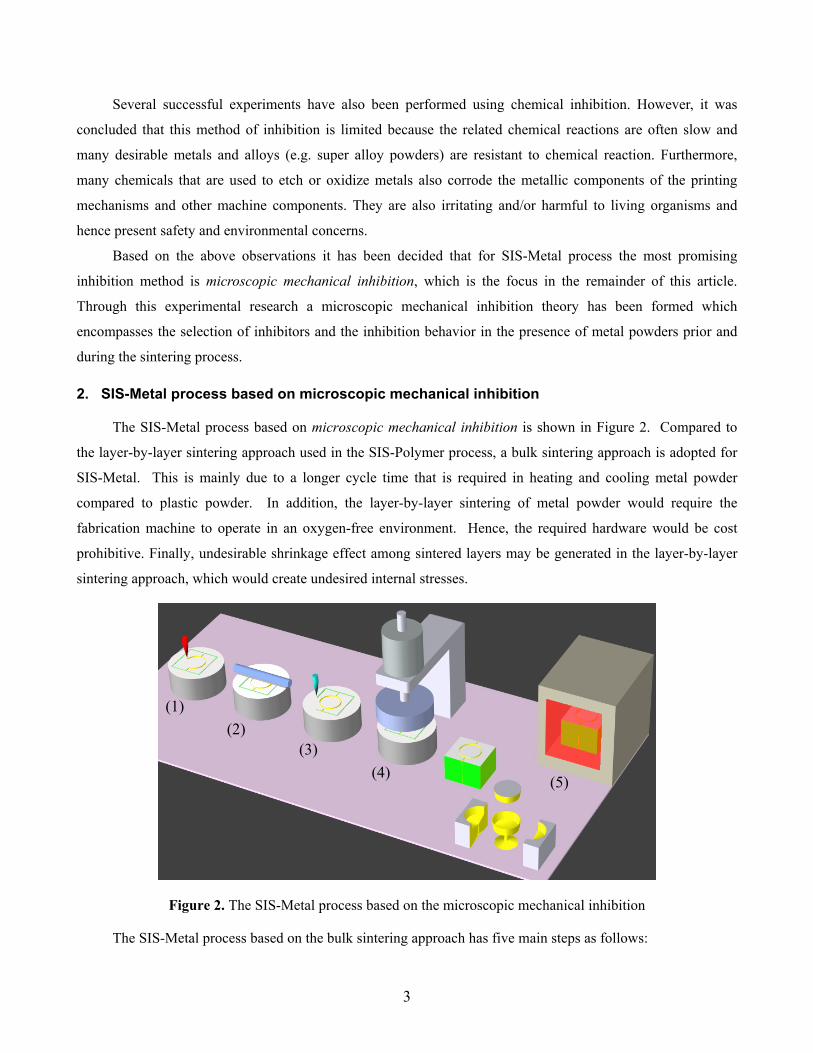
2. SIS-Metal process based on microscopic mechanical inhibition
The SIS-Metal process based on microscopic mechanical inhibition is shown in Figure 2. Compared to
the layer-by-layer sintering approach used in the SIS-Polymer process, a bulk sintering approach is adopted for
SIS-Metal. This is mainly due to a longer cycle time that is required in heating and cooling metal powder
compared to plastic powder. In addition, the layer-by-layer sintering of metal powder would require the
fabrication machine to operate in an oxygen-free environment. Hence, the required hardware would be cost
prohibitive. Finally, undesirable shrinkage effect among sintered layers may be generated in the layer-by-layer
sintering approach, which would create undesired internal stresses.
Figure 2. The SIS-Metal process based on the microscopic mechanical inhibition
The SIS-Metal process based on the bulk sintering approach has five main steps as follows:
(1) (2)
(3) (4) (5)

4
(1) Printing sintering inhibitor: A deposition nozzle with a fine orifice, or an inkjet print head, is used to
deliver a sintering inhibitor to the selected areas (i.e., layer profile) of the powder layer. If aqueous solutions
are used, the layer is dried before continuing with the subsequent layer.
(2) Laying a thin powder layer: Metal powder is spread as a thin layer over the build tank using a blade or a
roller.
(3) Creation of a boundary to contain part: A consolidating liquid is deposited on the powder bed at the
periphery of the part profile. The profile of this deposition may be a simple shape such as square or circle.
When all the layers are completed, such depositions will create a solid container around the area that
includes the 3D part. Using this container the completed green part can then be removed from the machine
and transferred to the sintering furnace. Interestingly, the salt solution used as the printed inhibitor can hold
the metal powder particles together after it is dried. The consolidating liquid for creating the container can
be different from the inhibitor solution, however.
(4) Heating and compression: A heater is used to evaporate water and other liquid additives (such as alcohol
which may be needed for breaking surface tension) in the printed inhibition sections. An optional motorized
press may be used to compact the metal powder layer after drying the inhibitor solution in order to create a
powder bed with increased density. Although layer compression can improve part density, it may also result
in part deformation. Successful implementation of compression requires careful study of the deformation
process so that the effect may be properly incorporated in the CAD model. The layer compression was not
performed in the study presented in this paper.
(5) Bulk sintering in an oven: After all the layers have been completed, a metal powder block is extracted from
the build tank and placed in a conventional sintering oven. A high temperature ceramic base plate, initially
placed on the build tank piston may be used for picking up the un-sintered loose powder block. After
sintering and cooling, the sintered metal block is removed from the oven. Finally, the fabricated part can be
extracted by removing the regions that are isolated by the inhibited powder areas.
2.1 Advantages of SIS-Metal
Before presenting the experimental procedure and related results let us fist compare the SIS-Metal process
with other metal fabrication processes in order to fully understand its unique properties and related advantages.
Metallic parts fabrication based on metal casting and powder metallurgy (P/M) [Kalpakjian and Schmid,
2006] requires tooling construction. However, the construction of such tooling can be expensive and time
consuming, especially for small quantities of parts or parts with complex geometry. In comparison, additive
manufacturing (AM) processes can be much faster and less expensive for such small lot or complex part
fabrication.

5
Currently, many AM processes have been developed for building metallic parts, such as Selective Laser
Sintering (SLS), 3D Printing (3DP), Fused Deposition Modeling (FDM), Direct Metal Laser Sintering (DMLS),
Laser Engineered Net Shaping (LENS), and Electric Beam Melting (EBM). These processes can be classified
based on the usage of binders and the sintering approach as shown in Figure 3.
(i) Usage of binders: Some AM processes such as SLS, 3DP, and FDM utilize certain binders in the
fabrication of green parts. For example, the SLS process uses polymer-coated metal powder [Wohlert, et
al. 1996; Pease 1998]; the 3DP process deposits droplets of liquid acrylic copolymer binder onto a bed
of metal powder [Sachs, et al., 2000; Pease 1998]; and the FDM process uses filaments that are made by
a mixture of binder and metal powder [Greul et al. 1995]. The binders in the fabricated green parts can
then be removed in a thermal debinding step. In comparison, AM processes such as DMLS, LENS, and
EBM can directly sinter metal powders layer-by-layer using high-power energy sources. For example,
the DMLS process can directly sinter metal powder without using polymer coating [Simchi, et al. 2001;
Kotila, et al. 2001; Behrendt and Shellabear, 1995]. The LENS process directly produces metal parts
from metal powder injected by a powder delivery nozzle [Atwood, et al. 1998]. The EBM process can
also directly melt metal powder in a controlled atmosphere chamber using an electron beam.
(ii) Sintering approach: Based on how metal powders are sintered into finished metallic parts, AM processes
can also be classified into bulk sintering and layer sintering. In the AM processes based on bulk
sintering of metal powders (e.g. SLS, 3DP, and FDM), green parts are fabricated first and are then
transferred to a sintering oven. In comparison, in the AM processes based on layer sintering of metal
powders (e.g. DMLS, LENS, and EBM), powders are sintered into the predefined geometry layer by
layer. As discussed before, bulk sintering can have advantages such as lower hardware cost, reduced
deformation and higher building speed.
Usage of binders
Sintering approach
Without the use of binders
With the use of binders
Bulk sintering
Layer sintering
SIS-MetalSLS
3D-printing
FDM
DMLS
LENS
EBM
Powder metallurgy
Require tooling
Additive process
Figure 3. A classification of the metallic part fabrication processes

6
Based on such a classification the SIS-Metal process is uniquely positioned among all the metallic part
fabrication processes because it is a layered fabrication process which is based on the bulk sintering approach
without using any binder. As shown in Figure 3, the SIS-Metal process is classified in the same category as the
traditional powder metallurgy process. However, as no tools are required, the SIS-Metal process may be
regarded as a moldless powder metallurgy process.
The SIS-Metal process has the following advantages.
• The hardware of the SIS-Metal process can be inexpensive. A green part can be fabricated using a print
head to deposit the inhibitor solution to powder layers; the green parts can then be sintered in a conventional
sintering oven, which is widely available in a typical powder metallurgy manufacturing facility.
• The SIS-Metal process is potentially fast. The inhibitor can be deposited using a multi-jet print head, which
has proven performance and impressive speed in other applications such as two-dimensional (2D) printing.
The printing time can be further reduced using a vector (instead of a raster) printer, because in most cases
the inhibitor needs to be deposited as a thin line only along the boundary of each layer profile.
• The SIS-Metal process can have less shrinkage and deformation since no de-binding is involved.
• Unlike LENS or DMLS, no complex supports are required in the SIS-Metal process since overhang features
are supported by powder volumes underneath.
Consequently, the development of the SIS-Metal process is important for future metallic part fabrication.
Figure 4. The SIS prototype machine
3. Experimental Procedure A three-axis prototype machine has been developed as shown in Figure 4. In the machine a single print
nozzle with an orifice size of 0.005” (0.127 mm) is used. The large orifice size of the nozzle allows the trial of
different inhibitors at different viscosity levels. The printing nozzle used has an electro-magnetic solenoid valve
7
for droplet printing. The deposited droplets from the nozzle are 300 nanoliters and are dispensed with a
frequency of 1500 HZ. The nozzle moves in the X and Y axes by stepper motors with a continuous speed of 31
mm/second. A heater has been incorporated for heating up every layer after printing the inhibitor. The heater
can heat up every layer up to 170oC to evaporate the liquid in the inhibitor solution.
Metal powder: Bronze powder has been the choice of metal powder in this research because of its its relative
ease of sintering and because of the popularity of bronze parts. Mixed, partially alloyed and fully alloyed bronze
powders have been investigated for use in this research project. Sintered parts with fully alloyed bronze powders
showed the best mechanical properties and the least shrinkage. In addition to copper (about 90%), the bronze
powder used in our experiments has the following chemical compositions:
Tin: 10% Lead: 0.025% Zinc: 0.04% Iron: 0.058% Phosphorous: 0.085%
Metal powders with different mesh sizes and shapes have also been examined. The finer the grain size,
the better the sintering process will be. However, if the grain size is too small it would be difficult to spread the
powder as a uniform layer. The most suitable grain size was observed to be 325 meshes or 44 micron. The
shape of metal powder is another important factor. The density of green parts is directly related to the packing
density of the powder bed. The packing density of spherical powder is better than other shapes. Therefore,
spherical fully alloyed bronze powder with 44 micron grain size was used in this study. The powder particle size
has the following distribution:
325 Mesh (44 Micron) 98.7 % 200/325 Mesh (44/75 Micron) 1.3 %
Inhibitor selection: In our study, salts have been chosen as the best inhibitor candidates, since salts are usually
inexpensive and safe for both human and environment. Salt crystals can be easily and quickly formed from the
printable salt solution state. The following important factors need to be considered in choosing an appropriate
salt candidate: (1) the melting temperature of salt crystals must be higher than the sintering temperature of
metallic powder; (2) the initial salt crystal size must be significantly smaller than the size that is yielded under
early sintering temperature of about 170-200 oC; (3) molecular mass of the salt solution and its surface tension
should be small such that it can have sufficient penetration in metal powder; and (4) The salt solution should
have a high solubility for nucleating a higher amount of crystals from a droplet.
Accordingly, the best inhibitor was identified to be aluminum sulfate. The properties of aluminum sulfate
are shown in Table 1. The inhibitor is achieved by solving 32 grams of aluminum sulfate anhydrous in 130 ML
of water at room temperature with 30 ML of isopropyl alcohol. Isopropyl alcohol is added to the inhibitor in
order to break the surface tension of the solution so that the inhibitor can easily penetrate the printed sections.

8
Table 1. Properties of aluminum sulfate
Molecular formula Al2(SO4)3
Molar mass 342.15 g/mol (anhydrous)
Melting point 770 °C
Solubility in water 31.2 g/100 mL (0 °C)
36.4 g/100 mL (20 °C) 89.0 g/100 mL (100 °C)
Solubility in alcohol and acids slightly soluble in alcohol and dilute mineral acids
Green part fabrication procedure: The 3-Dimensional CAD model of the part to be built is first sliced in a set
of layers with equal thickness. Depending on the part geometry, the layer thickness in our tests varied from 0.25
mm to 1 mm. For the parts shown in Figures 7 and 8 the layer thickness is 0.5 mm. For every layer the platform
of the SIS prototype machine goes down a layer thickness to accommodate the powder for the next layer to be
built. After the metal powder is spread, the print nozzle which can move along both X and Y axes prints the
inhibitor on the sections to be prevented from bonding by sintering. The inhibitor is also printed on the boundary
of the part to create a solid container around the area that contains the 3D part. After inhibitor printing is
completed the heater heats up the layer to dry up the inhibitor solution. As shown in Figure 2, the process then
repeats for other layers. After all layers are built the fabricated green part is transferred to a sintering furnace.
The sintering path in the oven is discussed as follows.
Sintering path: The sintering happens in an inert environment with Argon gas. Various sintering paths have
been tested. A sintering path that yields reasonably small shrinkage is shown in Figure 4 where the part is first
sintered at 600oC for 20 minutes; the temperature is then increased to 825oC to sinter the part for 30 minutes;
finally the part is slowly cooled down. A two-stage sintering process may also be used in which case the part
would be removed from the oven before being fully sintered; after separating the inhibited area the part can then
be put back to the oven for being fully sintered. Note that during the sintering process there would be shrinkage
distortion due to the different shrinkage rate of the the printed and un-printed sections. However, such difference
would be small due to the fact that in most instances only the boundary of the part’s cross section is treated with
the inhibitor, not the whole volume of the unwanted sections.
0100200300400500600700800900
0 50 100 150 200 250 300
Time(sec.)
tem
pera
ture
(cen
tigra
de)
Figure 5. A sintering path used in the experiments

9
(a) Before sintering (b) After sintering
Figure 6. An inhibition test using aluminum sulfate
4. Experimental Results An inhibition test using aluminum sulfate is shown in Figure 6. The solution of aluminum sulfate is first
printed into the powder bed (Figure 6.a). After sintering the sections with printed inhibitors are very brittle and
easily be broken away, while other regions that do not contain salt are sintered properly with good strength
(Figure 6.b). Two more examples of fully sintered bronze parts made are shown in Figures 7 and 8. Note that
the print nozzle used in our testbed has a low resolution (~0.13 mm). Accordingly the lines on the parts are
relatively coarse. As illustrated by other commercial processes such as 3DP, improving the nozzle resolution
can lead to drastically better surface quality.
Figure 7. A test bronze part can be separated from other portions after sintering
Figure 8. A test bronze part with internal holes
Inhibited sections with printed inhibitors (powders can be separated easily) Separation
lines
Fully sintered section

10
The properties of the bronze part shown in Figure 7 have been determined and listed tested in Table 2.
Table 2. Mechanical properties of a bronze part build by the SIS process.
Shrinkage ( Linear hrinkage) 6%-8%
Hardness ( Brinells Hardness) 60
Ultimate Tensile Strength 30,000 psi
Density 6.8 gr/Cu.cm.
Before Sintering After Sintering
With
out S
alt
W
ith S
alt
Figure 9. The SEM pictures of different samples. (a): a sample that is unsintered and without salt; (b): a sample that is sintered and without salt; (c): salt crystals are embedded in a sample that is unsintered and with salt; (d): metal powder particles are covered by ceramic particles and other substances in a sample that is sintered and with salt
The remainder of this section is devoted to the discussion of the underlying sintering inhibition
mechanism in the SIS-Metal process. To the best of our knowledge, most researchers in the field of powder
metallurgy focus on methods to “enhance” the sintering process through such methods as development of
Salt crystal Ceramic (Al2O3)
Other substance
(d) (c)
(a) (b)

11
sintering additives. No research has been found that focuses on the ways of effectively inhibiting metal
sintering. In [German, 1994] it is briefly mentioned that powder oxidation, adsorbed organic films, and the
presence of surface coating like silica have undesirable impact on sintering. However, methods of imposing such
effects have not been presented. In the field of ceramics Smith and Yanina [2002] reported on inhibition of
sintering of aluminum oxide powder in the heat intensive process of producing this powder. These researchers
demonstrated that the use of surface dopants/modifiers (magnesium, phosphorus, and iron) can inhibit low-
temperature sintering in nanocrystalline α-Al2O3, hence yielding fine aluminum oxide powder (instead of the
unwanted sintered chunks of this ceramic).
Various tests have been performed in this research in order to understand the inhibition mechanism in the
presence of printed salt in metal powder. A scanning electron microscope (SEM) is used to examine the
interactions between metal powder particles and salt crystals in the SIS-Metal process. The SEM pictures of the
bronze powder with and without salt, and also before and after sintering are shown in Figure 9. It should be
noted that the sample without salt was not fully sintered so that the related SEM image could be produced.
Based on these SEM pictures it can be observed that the formation of salt crystals plays a big role in preventing
metal particles from being properly fused in the course of sintering.
To explain the inhibition phenomenon as shown in our experimental results, we present two inhibition
mechanisms as follows. We believe both of them contribute to the results as shown in Figure 7.
(1) The separation of metal powders due to the expansion of salt crystals into decomposed particles
During the SIS-Metal process the salt solution is first printed in the selected areas of metal powder. In the
presence of moderate heat the water content of the salt solution evaporates; hence, salt crystals form between the
metal powder particles in the printed area (refer to Figure 9.c). When the green part is moved to the sintering
furnace in the early stages of sintering, the inorganic crystal salt, which has high melting temperature, rapidly
expands in size when heated. The expanded crystal salt then starts to decompose at a temperature around 500°C
[Tagawa, 1984; Apte, et al., 1988; Pelovski, et al., 1992]. The decomposition of aluminum sulfate during the
sintering process is shown as follows:
223
332342
223)(
OSOSOSOOAlSOAl
+→+→
(Eq. 1)
The decomposed salt particles create a gap in the boundary due to their volumetric growth in the
transformation process. Therefore, the affected metal powder particles in the printed sections can be prevented
from proper sintering at the sintering temperature of metal powder. To observe the extent of expansion of
aluminum sulfate (our choice of salt) an experiment was performed in isolation from metal powder. In our
experiment with aluminum sulfate it was noticed that salt crystals decompose and grow rapidly during the
heating process. As shown in Figure 8, the volumetric size of the salt sample is almost quadrupled based on the
measured dimensions.
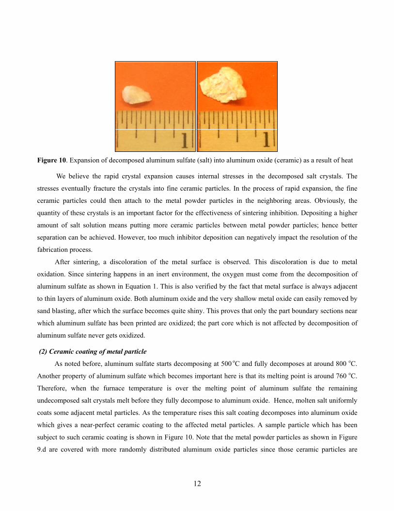
12
Figure 10. Expansion of decomposed aluminum sulfate (salt) into aluminum oxide (ceramic) as a result of heat
We believe the rapid crystal expansion causes internal stresses in the decomposed salt crystals. The
stresses eventually fracture the crystals into fine ceramic particles. In the process of rapid expansion, the fine
ceramic particles could then attach to the metal powder particles in the neighboring areas. Obviously, the
quantity of these crystals is an important factor for the effectiveness of sintering inhibition. Depositing a higher
amount of salt solution means putting more ceramic particles between metal powder particles; hence better
separation can be achieved. However, too much inhibitor deposition can negatively impact the resolution of the
fabrication process.
After sintering, a discoloration of the metal surface is observed. This discoloration is due to metal
oxidation. Since sintering happens in an inert environment, the oxygen must come from the decomposition of
aluminum sulfate as shown in Equation 1. This is also verified by the fact that metal surface is always adjacent
to thin layers of aluminum oxide. Both aluminum oxide and the very shallow metal oxide can easily removed by
sand blasting, after which the surface becomes quite shiny. This proves that only the part boundary sections near
which aluminum sulfate has been printed are oxidized; the part core which is not affected by decomposition of
aluminum sulfate never gets oxidized.
(2) Ceramic coating of metal particle
As noted before, aluminum sulfate starts decomposing at 500 oC and fully decomposes at around 800 oC.
Another property of aluminum sulfate which becomes important here is that its melting point is around 760 oC.
Therefore, when the furnace temperature is over the melting point of aluminum sulfate the remaining
undecomposed salt crystals melt before they fully decompose to aluminum oxide. Hence, molten salt uniformly
coats some adjacent metal particles. As the temperature rises this salt coating decomposes into aluminum oxide
which gives a near-perfect ceramic coating to the affected metal particles. A sample particle which has been
subject to such ceramic coating is shown in Figure 10. Note that the metal powder particles as shown in Figure
9.d are covered with more randomly distributed aluminum oxide particles since those ceramic particles are

13
generated by aluminum sulfate before it reaches its melting point. Since the sintering temperature of aluminum
oxide is much higher than that of Bronze powders, the metal powder particles that are covered with ceramic
particles do not fuse with neighboring particles during the sintering process.
Figure 11. The SEM pictures of different samples: (Left): a metal powder particle before sintering; (right): a metal powder particle that is coated with ceramic
Figure 12. The SEM image of a sintered sample and the related EDS analysis result
Thermogravimetric test shows that after the sintering process the weight loss of the decomposed
aluminum sulfate is nearly 80% of its original weight1. Energy dispersive x-ray spectroscopy (EDS) analysis has
been performed to determine the existence of aluminum oxide on surfaces of metal powders. The analysis on
other randomly selected particles dispersed on and between metal particles also showed other substances. For
1 Note that Equation 1 shows about 69% weight loss but the salt crystals used in this experiment originally had a significant water content.

14
example, a test result on such substances is shown in Figure 12, which illustrates large peaks on magnesium
(possibly present in small amount in the metal powder alloy) and sulfur (in the form of sulfur dioxide and sulfur
trioxide – see [Stern, 2001]). These other substances may also contribute to the inhibition effect in unknown
ways.
Discussion: Sintering is a physically complex phenomenon which results in numerous structural changes for
improved mechanical properties. German [1994] divided the powder sintering process into six stages: (1) inter-
particle bonding; (2) neck growth; (3) pore channel closure; (4) pore rounding; (5) pore shrinking; and (6) pore
coarsening. Different stages of sintering depend on various mass transport mechanisms. The transport
mechanisms include viscous flow, plastic flow, evaporation-condensation, lattice (volume) diffusion, grain
boundary diffusion, and surface diffusion. The initial stage of sintering mainly depends on surface diffusion. In
the SIS-Metal process salt crystal expansion happens at a temperature that is much lower than the sintering
temperature of metal powder. The expansion generates inhibitor particles that can also prevent point contacts
between neighboring metal particles. Hence, several stages of sintering can be prevented from occurring in the
SIS-Metal process. The identified inhibition mechanisms can provide some guidance for future developments of
the SIS-Metal process.
5. Conclusion
The SIS-Metal process based on microscopic mechanical inhibition has been investigated. The SIS-Metal
process can provide benefits such as low cost and fast building speed for metallic parts fabrication. Our
experimental results have demonstrated that the SIS-Metal process can fabricate metal parts with desirable
properties. Based on the experimental results an inhibition mechanism for preventing metal particles from
sintering has been identified and described. The inhibition mechanism is based on the formation of salt crystals,
expansion and decomposition of salt and subsequent transition to ceramic particles throughout the sintering
process. By establishing the basics of the process this paper guides future researchers toward process
improvement through attainment of higher accuracy and fabrication speed, and investigation of applicability of
the process to other metal powder materials.
Acknowledgement
The authors wish to thank Prometal for its generous financial and equipment support as well as helpful guidance
throughout this research. Additionally, we would like to thank Professor Thieo Hogen-Esch of USC Chemical
Engineering Department for sharing his valuable insights about decomposition of metal salts.
15
References
Apte, N. G., Kiran, E., and Hassler, J.C. (1988), “ Kinetic modeling of thermal decomposition of aluminum
sulfate”, Chem Eng. Comm, Vol. 74, pp 47-61.
Asiabanpour, B., Palmer, K. and Khoshnevis, B. (2004), “An experimental study of surface quality and
dimensional accuracy for selective inhibition of sintering”, Rapid Prototyping Journal, Vol. 10 No. 3, pp.
181-92.
Asiabanpour, B., Khoshnevis, B. and Palmer, K. (2006), “Advancements in the selective inhibition sintering
process development”, Virtual and Physical Prototyping Journal, Vol. 1 No. 1, pp. 43-52.
Atwood, C., Griffith M., Harwell L., Schlienger E., Ensz M., Smugeresky J., Romero T., Greene D., and
Reckaway D. (1998), “Laser engineered net shaping (LENS): a tool for direct fabrication of metal parts,”
Sandia National Labs, http://mfgshop.sandia.gov/1400_ext/icaleo98.pdf.
Behrendt, U., and Shellabear M. (1995), “The EOS Rapid Prototyping Concept,” Computers in Industry, Vol. 28.
German, R.M. (1994), Powder metallurgy science, 2nd ed., Metal Powder Industries Federation, Princeton.
Greul, M., Pintat T., and Greulich M. (1995), “Rapid prototyping of functional metallic Parts”, Computers in
Industry, Vol. 28, No. 1, pp. 23-28.
Kalpakjian, S., and Schmid, S. (2006), Manufacturing Engineering and Technology, Pearson Prentice Hall, 5th
edition.
Khoshnevis, B., Asiabanpour B., Mojdeh M., and Palmer K. (2003), “SIS – a new SFF method based on powder
sintering”, Rapid Prototyping Journal, Vol. 9, No. 1, pp. 30-36.
Kotila, J., Nyrhilä O., and Syvänen T. (2001), “Direct steel component manufacturing using direct metal laser
sintering”, Advances in Powder Metallurgy & Particulate Materials – 2001, MPIF, Princeton, U.S.A.
Pease L. F. (1998), “Selective laser sintering,” ASM Handbook Volume 7: Powder Metal Technicnologies and
Applications.
Pelovski, Y., Pietkova, W., Grunchov, I., Pacewska, B. and Pysiak, J. (1992), “ The thermal decomposition of
aluminum sulfate in different gas phase environments” Thermochimica Acta, Vol. 205, pp.219-224.
Sachs, E., Allen S., Cima M., Brancazio D., Serdy J., Polito B., Ables D., and Rynerson M. (2000), “Three
dimensional printing: a candidate for the production of powder metal parts,” Advances in Powder Metallurgy
and Particulate Materials, Vol. 1, pp. 139-152.
Simchi, A., Petzoldt F., and Pohl H., (2001) “Direct metal laser sintering: material consideration and
mechanisms of particle bonding,” The International Journal of Powder Metallurgy, vol. 37, n. 2.
Smith, R. L. and Yanina S. V. (2002), “Inhibition of sintering and surface area loss in phosphorus-doped
corundum derived from diaspore”, Journal of Am. Ceram. Soc., Vol. 85, No. 9, pp. 2325-30.
Stern, K. H., (2001), High temperature properties and thermal decomposition of inorganic salts with oxyanions,
CRC Press, Ltd, pp. 74-75.
16
Stuecker, J., Cesarano J., and Hirschfeld D. (2003), “Control of the viscous behavior of highly concentrated
mullite suspensions for robocasting”, Journal of Materials Processing Technology, Vol. 142, No. 2, pp. 318-
325.
Tagawa, H. (1984), “Thermal decomposition temperatures of metal sulfates”, Thermochemica Acta, Vol.80, pp.
23-33.
Wohlert, M., Bourell D., Lee G., and Beaman J. (1996), “Production of full density metal-matrix composite by a
combined selective laser sintering/metal infiltration process,” Processing and Fabrication of Advanced
Materials V, The Minerals, Metals & Materials Society.