metal stud walls magnum plus - jewsonassets.jewson.co.uk/product-docs/8463/8463.pdf · metal stud...
TRANSCRIPT

M E TA L S T U D W A L L SMAGNUM PLUS
1
51 Single Stud construction, MAGNUM PLUS single boarded52 Single Stud construction, MAGNUM PLUS double boarded
Guide notes� Where Db is succesfuly used:
All projects with an increased requirement for sound insulation
Compared to conventional internal walls,non-load-bearing partition walls will achive:� fast dry construction
� increase in useable floor space
� reduced weight of walls
� fire protection F 30/F 90
Contents Page
Technical and construction dataMAGNUM PLUS profiles. . . . . . . . . . . . . . . . . . . . . . . . . 2
Fire protection . . . . . . . . . . . . . . . . . . . . . . . . . . . . . . . . . . . 3
Systems 51– 52 . . . . . . . . . . . . . . . . . . . . . . . . . . . . . . . . 4–5
Junction details . . . . . . . . . . . . . . . . . . . . . . . . . . . . . . . . . 6
Door frame construction . . . . . . . . . . . . . . . . . . . . . . . 7
Bracket loads . . . . . . . . . . . . . . . . . . . . . . . . . . . . . . . . . . . 8
Material requirements . . . . . . . . . . . . . . . . . . . . . . . . . . 9
Forms for tendering . . . . . . . . . . . . . . . . . . . . . . . . . . . . . 10
Construction and assembly . . . . . . . . . . . . . . . . . . . . 11
Advantages . . . . . . . . . . . . . . . . . . . . . . . . . . . . . . . . . . . . . . 12
Acoustic Offensive
52 – Single stud construction MAGNUM PLUS profile double boarded
51 – Single stud construction MAGNUM PLUS profile single boarded
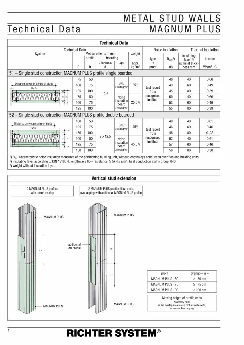
M E TA L S T U D W A L L STe c h n i c a l D a t a M A G N U M P L U S
Vertical stud extension
Technical Data
2 MAGNUM PLUS profiles with boxed overlap
2 MAGNUM PLUS profiles flush ends,overlapping with additional MAGNUM PLUS profile
Moving height of profile endsAssembly help:
in the overlap area fasten profiles with rivets,screws or by crimping
profil overlap – ü –
MAGNUM PLUS 50 ≥ 50 cm
MAGNUM PLUS 75 ≥ 75 cm
MAGNUM PLUS 100 ≥ 100 cm
2
Thermal insulationNoise insulationTechnical Data
type of
proof
test reportfrom
recognisedinstitute
Rw,R1)
dB
k value
W/(m2 · K)
insulating layer 2)
nominal thick-ness mm
weight
appr.kg/m2
Measurements in mmSystemprofile boarding
thickness typedhD
40 40 0.66
43 60 0.49
45 80 0.39
50 40 0.66
53 60 0.49
55 80 0.39
253)
25,53)
GKB≥ 8,8 kg/m2
Noiseinsulation
board≥ 9,6 kg/m2
12.5
75 50
100 75
125 100
75 50
100 75
125 100
test reportfrom
recognisedinstitute
453)
45,53)
1) Rw,R Characteristic noise insulation measures of the partitioning building unit, without lengthways conduction over flanking building units2) insulating layer according to DIN 18165-1, lengthways flow resistance: ≥ 5kN x s/m4; heat conduction ability group: 040.3) Weight without insulation layer.
GKB≥ 8,8 kg/m2
Noiseinsulation
board≥ 9,6 kg/m2
2�12.5
40 40 0.61
46 60 0.46
48 80 0.,38
52 40 0.61
57 60 0.46
56 80 0.38
100 50
125 75
150 100
100 50
125 75
150 100
Distance between centre of studs62.5
dh D
d
Distance between centre of studs62.5
dh D
d
MAGNUM PLUS
MAGNUM PLUS
ü
MAGNUM PLUS
MAGNUM PLUS
additionaldB profile üü
Distance between centre of studs62.5
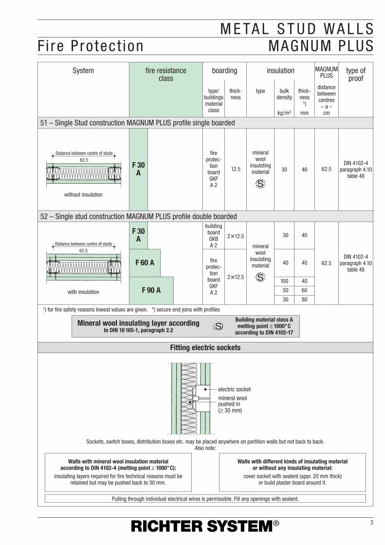
Fitting electric sockets
52 – Single stud construction MAGNUM PLUS profile double boarded
51 – Single Stud construction MAGNUM PLUS profile single boarded
F 90 A
F 60 A
F 30A
F 30A
M E TA L S T U D W A L L SFi re P ro tec t ion MAGNUM PLUS
3
System fire resistance class
boarding insulation MAGNUMPLUS
distancebetweencentres– a –cm
thick-ness
1)
mm
bulkdensity
kg/m3
type
DIN 4102-4paragraph 4.10
table 4830 40
thick-ness
type/buildingsmaterial
class
fireprotec-
tion boardGKFA 2
62.512.5
mineralwool
insulatingmaterial
S
30 40
40 40
100 40
50 60
30 80
DIN 4102-4paragraph 4.10
table 48
fireprotec-
tion boardGKFA 2
buildingboardGKBA 2
2�12.5
2�12.5
type ofproof
1) for fire safety reasons lowest values are given. *) secure end joins with profiles
mineralwool
insulatingmaterial
S
Mineral wool insulating layer accordingto DIN 18 165-1, paragraph 2.2
Building material class Amelting point ≥ 1000°C
according to DIN 4102-17S
Pulling through individual electrical wires is permissible. Fill any openings with sealent.
Sockets, switch boxes, distribution boxes etc. may be placed anywhere on partition walls but not back to back.Also note:
Walls with mineral wool insulation material according to DIN 4102-4 (melting point ≥ 1000°C):
insulating layers required for fire technical reasons must beretained but may be pushed back to 30 mm.
Walls with different kinds of insulating material or without any insulating material:
cover socket with sealent (appr. 20 mm thick) or build plaster board around it.
electric socket
mineral woolpushed in(≥ 30 mm)
62.5
Distance between centre of studs62.5
without insulation
with insulation
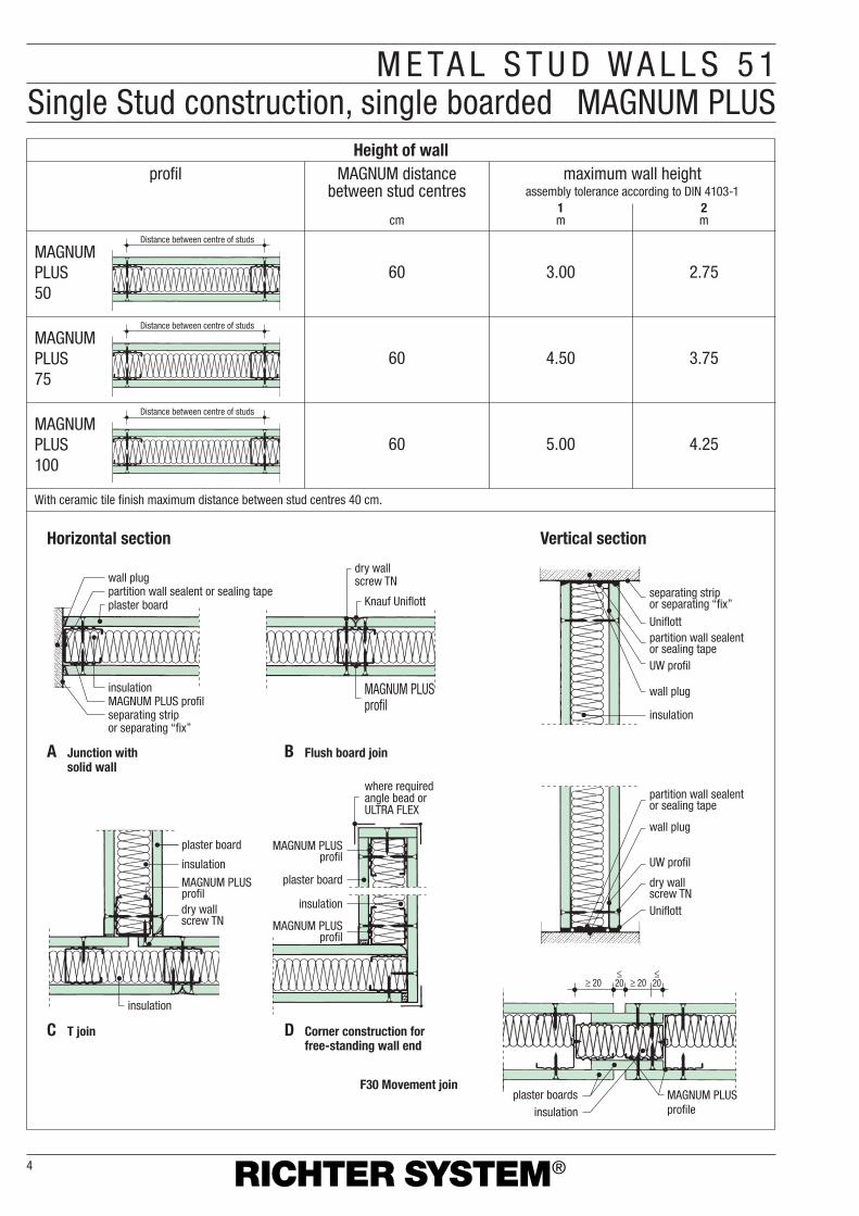
M E TA L S T U D W A L L S 5 1Single Stud construction, single boarded MAGNUM PLUS
Height of wallprofil MAGNUM distance
between stud centresmaximum wall height
assembly tolerance according to DIN 4103-11mcm
With ceramic tile finish maximum distance between stud centres 40 cm.
2m
4
60 3.00 2.75
60 4.50 3.75
60 5.00 4.25
MAGNUMPLUS50
Distance between centre of studs
Distance between centre of studs
Distance between centre of studs
MAGNUMPLUS75
MAGNUMPLUS100
Horizontal section
A Junction withsolid wall
C T join D Corner construction forfree-standing wall end
F30 Movement join
B Flush board join
Vertical section
wall plugpartition wall sealent or sealing tapeplaster board
insulationMAGNUM PLUS profilseparating strip or separating “fix”
insulation
dry wall screw TN
plaster board
insulation
MAGNUM PLUSprofil
insulation
plaster board
MAGNUM PLUSprofil
where requiredangle bead orULTRA FLEX
MAGNUM PLUS profil
dry wall screw TN
Knauf Uniflott
MAGNUM PLUSprofil
separating stripor separating “fix”
Uniflott
UW profil
wall plug
insulation
partition wall sealentor sealing tape
partition wall sealentor sealing tape
wall plug
dry wallscrew TNUniflott
UW profil
MAGNUM PLUS profile
plaster boards
≥ 20 ≥ 20≤20
≤20
insulation
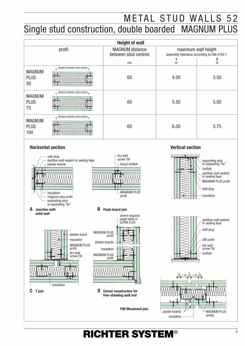
M E TA L S T U D W A L L S 5 2Single stud construction, double boarded MAGNUM PLUS
Height of wallprofil MAGNUM distance
between stud centresmaximum wall height
assembly tolerance according to DIN 4103-11mcm
2m
5
60 4.00 3.50
60 5.50 5.00
60 6.50 5.75
MAGNUMPLUS50
MAGNUMPLUS75
MAGNUMPLUS100
distance between stud centres
distance between stud centres
distance between stud centres
Horizontal section
A Junction withsolid wall
C T join D Corner construction forfree-standing wall end
F90 Movement join
B Flush board join
Vertical section
wall plugpartition wall sealent or sealing tapeplaster boards
insulationmagnum plus profilseparating strip or separating “fix”
insulation
dry wall screw TN
plaster board
insulation
MAGNUM PLUSprofil insulation
plaster boards
MAGNUM PLUS profil
where requiredangle bead orULTRA FLEX
MAGNUM PLUS profil
dry wall screw TN
Knauf Uniflott
MAGNUM PLUS profil
separating strip or separating “fix”Uniflott
MAGNUM PLUS profil
wall plug
insulation
partition wall sealent or sealing tape
partition wall sealent or sealing tape
wall plug
dry wall screw TNUniflott
UW profil
MAGNUM PLUS profils
plaster boards
≥ 20 ≥ 20≤20
≤20
≤20
insulation

M E TA L S T U D W A L L SJo ins MAGNUM PLUS
6
plasterboard fixing
sound values not tested
diagonal bracing with notched tape
for fire proofing use filler
UW profilpartition wall sealent
or sealing tape
Join 52 with boarded ceiling Join with dry floor
Uniflott
wall plug
strip of plaster board edging strip
aluminium clip-on plinth
Join with false join due to fire regulations
Join with untreated floor surface
dry wall screw TN
partition wall sealent or sealing tape
edge protection profile 23/13
with fire protectiona = 10-20 mm
without fire potectiona = 10-30 mm
aa
10≥≥
a≥ 2
0
for fire proofing use filler
UW profil
insulation
plasterboards
wall plug
aluminium clip-on plinth
screed floor
Sliding join 52 in case of fire resistance and/or sound resistance
Join with screed floor,separated
≥ 10 ≥ 20
Uniflott
ceiling, e.g. 9.1/D113
separating strip
inner corner profile
dry wall screw TN
plasterboards
Sliding join together with closed plasterboard ceiling
T join with inner corner profiles
Vertical section
Horizontal cut

M E TA L S T U D W A L L SDoor f rame construct ion MAGNUM PLUS
7
maximum door weightsUA-Profil
UA 50 UA 75 UA 100≤ 50 kg ≤ 75 kg ≤ 100 kg
625/2000 625/20001) 610/1998 635/2010
750/2000 750/20001) 735/1998 760/2010
875/2000 875/20001) 860/1998 885/2010
1000/2000 1000/20001) 985/1998 1010/2010
wooden/block or plated
framemm
steel fast-fit frame
mm
aluminium topframe
mm
DIN 18100w�hmm
standardsize
aperture measurements
1) for aluminium top frame 2135 mm height is possible
measurement of aperture
UA profile
Lintel profile
Door post angle bracket – TOP –use supplied bolts
Door post angle bracket – BOTTOM – use supplied bolts
UA profile
Door post angle bracket – TOP – fasten using wall plugs “L” 8/100
aperture measurementOption UA
UA profil 2 mmdry wall screw TB
Door post angle bracket51
aperture measurementOption UA
UA profil 2 mmdry wall screw TB
Door post angle bracket52
Option UA profile
Remove plastic strips from door post angle brackets
Sliding ceiling junction
Option UA profile

M E TA L S T U D W A L L SBracke t l oads MAGNUM PLUS
8
Diagram 1:Bracket load tolerance up to 0.4 kN/m length of wall
Applicable to system:51
Diagram 2:Bracket load tolerance up to 0.7 kN/m length of wall
Applicable to system:52
Example: depth of cupboard 30 cm, width of cupboard 80 cmIn the diagram, start at depth of cupboard of 30 cm 1 go vertically up to the line width of cupboard 80 cm 2, From that point of intersection go horizontally to the left and – read 3 : 50 kg is the permissiblecupboard weight for a cupboard with those measurements.
According to DIN 18183 metal stud walls may carry bracket loads up to 0.7 kN/m length of wall subject to arm (height of cupboard ≥ 30 cm) and eccentricity (depth of cupboard ≤ 60 cm) are being taken into account.Distance between plugs ≥ 75 mm.
Bracket loads should be fastened with a minimum of 2 plasterboard fixings, either plastic or metal,e.g.Tox Universal, Fischer Universal, Molly screw anchor.
Bracket loads above 0.7 kN/m up to 1.5 kN/m length of wall require support brackets or tie bars on the lower structure.
Lighter objects such as pictures may be attached with X hooks.
Load Load Load5 kg 10 kg 15 kg
Example: depth of cupboard 45 cm, width of cupboard 80 cmIn the diagram, start at depth of cupboard of 45 cm 1 go vertically up to the line width of cupboard 80 cm 2, From that point of intersection go horizontally to the left and – read 3 : 65 kg is the permissiblecupboard weight for a cupboard with those measurements.
plug load capacitytension load and shearing load
thickness plastic metalof boards plasterboard fixing plasterboard fixing
� 8 or � 10 mm screw M5 or M6mm kg kg
12.5 25 30
≥ 2 � 12.5 40 50
plastic plasterboard fixing metal plasterboard fixing
width of cupboard
≥ 30
cm
heigh
t of c
upbo
ard
depth of cupboard
3 2
1
width of cupboard in cm
2 at
tach
men
t poi
nts
mor
e th
an 2
at
tach
men
ts p
oint
s
depth of cupboard in cm
maximum permissible weight of cupboard in kg
cm 10 20
100110120
908070
5060
40302010
kg
30 40 50 60
40
60
80
100
120
cm
3 2
1
width of cupboard in cm
2 at
tach
men
t poi
nts
mor
e th
an 2
at
tach
men
ts p
oint
s
depth of cupboard in cm
maximum permissible weight of cupboard in kg
cm 10 20
100908070605040302010
kg
30 40 50 60
406080
100120cm

M E TA L S T U D W A L L SM a t e r i a l r e q u i r e m e n t s MAGNUM PLUS
Material requirements
5251unitmaterial description
Floor constructionUW-Profil 50�40�0.6; 4.00 m long
or UW-Profil 75�40�0.6; 4.00 m long m 0.7 0.7or UW-Profil 100�40�0.6; 4.00 m long
MAGNUM-PLUS-Profil 50�50�0.6 mm;or MAGNUM-PLUS-Profil 75�50�0.6 mm; m 2.0 2.0or MAGNUM-PLUS-Profil 100�50�0.6 mm;
sealing tape30 / 3.0 mm roll 30 m B1
or 30 / 3.2 mm roll 30 m –or 50 / 3.2 mm roll 30 m – m 1.2 1.2or 70 / 3.2 mm roll 30 m –or 95 / 3.2 mm roll 30 m –
partition wall sealent units as required as required
nail-in plug35 mm paket 100 each
or 50 mm paket 100 eachor 60 mm paket 50 each units 1.6 1.6or 80 mm paket 50 eachor 100 mm paket 50 each
insulation(for fire regulations see page 3) m2 as required as required_____ mm thick
boardsplasterboard 12.5 mm≥ 8 kg/m2 GKB≥ 10 kg/m2 sound-proof board m2 2 4or fire proof board 12.5 mm
BLACK STAR dry wall screwsTN 3.5�35 mm paket 1000 each
units24 14
TN 3.5�42 mm paket 1000 each – 24
fillingjoint filler kg as required as required
reinforcement strip m as required as requiredcorner batten AL or galvanised 23/132.5 / 2.6 / 3.00 m long mcorner batten galvanised 31/312.5 / 2.6 / 3.00 m long m
as required as required
edge protection profilesRICHTER SYSTEM ULTRA-SERIE m
material for door constructionUA-Profil _________ �40�2.0 m as required as required
door frame angle bracket1 set consisting of:4 plug-in angles und 10 bolts set as required as requiredfor UA 50for UA 75for UA 100
lintel profile,precut for apertures:610 – 650 mm 735 – 775 mm860 – 900 mm 985 – 1025 mm set as required as requiredfor UA 50for UA 75for UA 100
These material requirements include materials for wall systems without any particular specifications.
Material requirements per m2 of wall without additions due to loss or cut-offs. Quantities are averages.Calculated surface (H = 2.75m; L = 4.00 m; A = 11.00 m2).
9
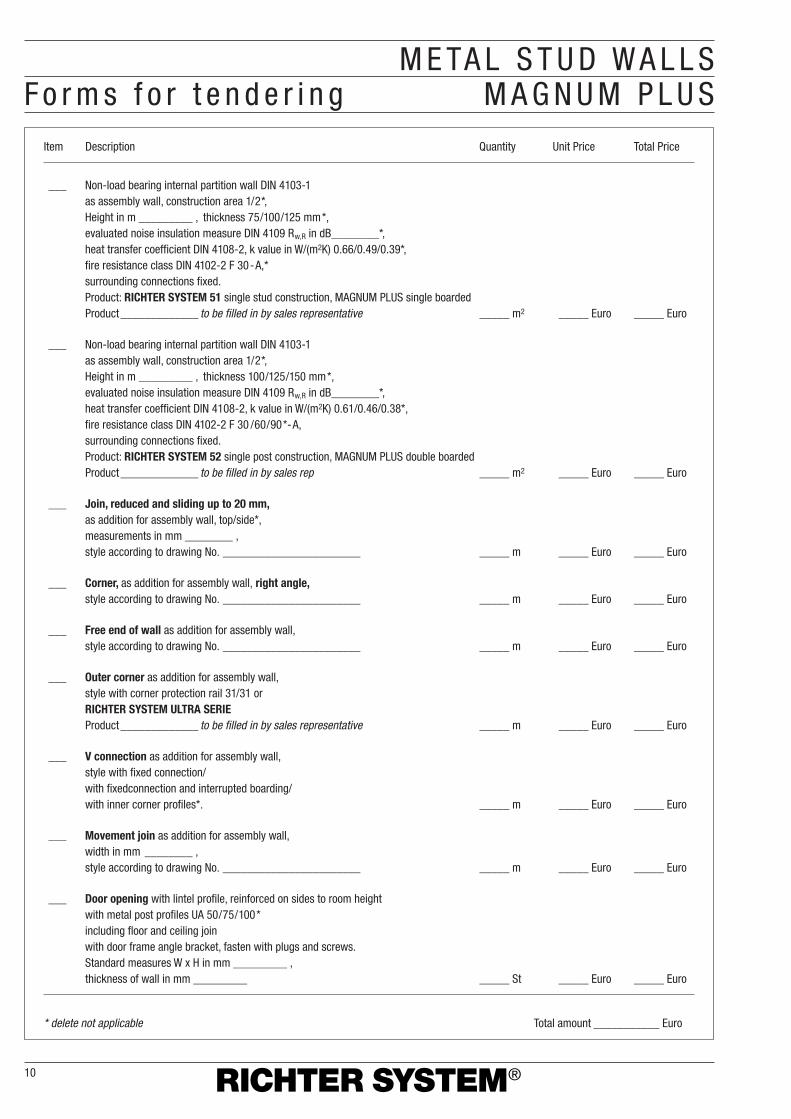
M E TA L S T U D W A L L SF o r m s f o r t e n d e r i n g M A G N U M P L U S
Item Description Quantity Unit Price Total Price
___ Non-load bearing internal partition wall DIN 4103-1as assembly wall, construction area 1/2*,Height in m _________ , thickness 75/100/125 mm*,evaluated noise insulation measure DIN 4109 Rw,R in dB________*,heat transfer coefficient DIN 4108-2, k value in W/(m2K) 0.66/0.49/0.39*,fire resistance class DIN 4102-2 F 30-A,*surrounding connections fixed.Product: RICHTER SYSTEM 51 single stud construction, MAGNUM PLUS single boardedProduct_____________ to be filled in by sales representative _____ m2 _____ Euro _____ Euro
___ Non-load bearing internal partition wall DIN 4103-1as assembly wall, construction area 1/2*,Height in m _________ , thickness 100/125/150 mm*,evaluated noise insulation measure DIN 4109 Rw,R in dB________*,heat transfer coefficient DIN 4108-2, k value in W/(m2K) 0.61/0.46/0.38*,fire resistance class DIN 4102-2 F 30 /60/90*-A,surrounding connections fixed.Product: RICHTER SYSTEM 52 single post construction, MAGNUM PLUS double boardedProduct_____________ to be filled in by sales rep _____ m2 _____ Euro _____ Euro
___ Join, reduced and sliding up to 20 mm,as addition for assembly wall, top/side*,measurements in mm ________ ,style according to drawing No. _______________________ _____ m _____ Euro _____ Euro
___ Corner, as addition for assembly wall, right angle,style according to drawing No. _______________________ _____ m _____ Euro _____ Euro
___ Free end of wall as addition for assembly wall,style according to drawing No. _______________________ _____ m _____ Euro _____ Euro
___ Outer corner as addition for assembly wall,style with corner protection rail 31/31 orRICHTER SYSTEM ULTRA SERIEProduct_____________ to be filled in by sales representative _____ m _____ Euro _____ Euro
___ V connection as addition for assembly wall,style with fixed connection/with fixedconnection and interrupted boarding/with inner corner profiles*. _____ m _____ Euro _____ Euro
___ Movement join as addition for assembly wall,width in mm ________ ,style according to drawing No. _______________________ _____ m _____ Euro _____ Euro
___ Door opening with lintel profile, reinforced on sides to room heightwith metal post profiles UA 50/75/100*including floor and ceiling joinwith door frame angle bracket, fasten with plugs and screws.Standard measures W x H in mm _________ ,thickness of wall in mm _________ _____ St _____ Euro _____ Euro
* delete not applicable Total amount ___________ Euro
10

M E TA L S T U D W A L L SConstruct ion + assembly MAGNUM PLUS
11
ConstructionRICHTER SYSTEM MAGNUM PLUS metal stud wallsconsist of a single stud construction for increasedsound protection requirements. Covered both sides with plasterboard fastened with screws.Plasterboarding may be either single or doublelayer. Height of walls according to DIN 18183.
The stud construction is fixed to the main building structur on all sides.Insulation materials complying with noise,thermal and fire proofing requirements as well as installations (electric, plumbing…) are built inside the hollow wall spaces.
Structural movement joins of the building haveto be built into the construction of the metalstud walls. Continuous walls need movementjoins at appr. every 15 m.
AssemblySubstructure� Profiles which are to join flanking walls need
either an application of sealing tape (for fireproofing B1) or partition wall sealent on the back.
� Attach perimiter profiles, with suitable fixing,to the main building structure. UW profiles50/75/100 according to DIN 18182-1 on to floorsand ceilings, MAGNUM PLUS profiles 50/75/100on to walls. Fastening distance 1m, on walls with minimum of 3 fastening points.
� Fastenings for flanking solid parts of the building:wall plugs/non-solid parts of the building:fastening elements which are suitable for theparticular building material.
� Include ≥ 10 mm sliding join to allow for foreseeable ceiling movment.
At a 62.5 cm distance between stud centres (for ceramic coating, single boarded, maximumof 42 cm) place stud profiles MAGNUM PLUS50/75/100 in a horizantal direction into the UW profiles and align.
Boarding� Boarding with vertically placed, room-high
plasterboards with minimum 1 cm clearingfrom untreated floor.
� For fire proofing requirements, seal offbottom join with filler, for noise proofingrequirements only, sealent may be used.
� Arrange long edges with staggered joins.
� Do not create flush join between plasterboardsand door frames.
� Build insulation materials and installations intohollow space.
51� Distance between screws 25 cm.� When using plasterboards which are not
room-high, stagger horizontal joins by at least400 mm. Filling top edge joins with paper joinsealing strips is recommended.
52� Screw centres for first layer 75 cm, and 25 cm
for the outer layer.
Join methodsFillers� Without join sealing strip: filling by hand with
Knauf Uniflott or Uniflott impregnated; with paperjoin strips: filling by hand with join filler Light ormachine filling with Ames machine and JointfillerSuper.
� Uniflott impregnated is in addition water proof and matches with impregnated plasterboards.
� Use Finish Pastös for the last finely applied coat of filler before sanding the plasterboard joins.
Execution� In case of multi-layered boarding fill the
joins of the lower layers. Oozing filler to be spread thinly with left-right movements (fir tree technique, see also page 12).Fill joins of outer layer.
� Also fill all visible screw heads.� Recommendation: fill interface joins of visible
boarding layers with paper join sealing strips,independent of filler.
� Knauf Special Base Coat K495 to be used as aspecial base coat to apply a full base coat toplasterboard surfaces using join fillers in order to regulate absorption and to achieve visualevenness. It is a system component which allowsto achieve surfaces with increased quality
requirements according to Note No. 2“Classification of filling work” of the IGG.
Processing temperature/climate� Only proceed with the filling when major
changes in the length of the plasterboards,e.g. as a result of changes in temperature or humidity, can no longer occur.
� During filling, the room temperature must not go below 10 ˚C.
� Even in case of poured asphalt screed only fill plasterboard joins after pouring thescreed.
Surface treatmentApply base coat before applying coat of paint or other coating. Combine base coat and topcoat/other coating according to manufacturer’sinstructions. The following coatings may beapplied to plasterboards:� Top coats: wash and grazing resistant
synthetic dispersion resin paints, paints withmulti-colour effect, oil paints, matt varnishes,alkyd resin paints, polyurethane varnishes(PUR), polymer resin paints, epoxy resin (EP),depending on use and requirements.
� Ceramic coatings.� Plaster: Knauf structured plaster, e.g.
synthetic resin plasters, thin plasters,
full-area plaster as for example Knauf Board-Finish; mineral plasterscombined with fillers with join strips.
� Wall paper: paper, textile or syntheticmaterial. Only use adhesives made of methylcellulose according to Special Note No. 16 (Merkblatt Nr.16), technicalguidelines for wall paper and adhesion work,Frankfurt/Main 1996, published by the Federal Committee for Paints andtrademark protection (BundesausschussFarbe und Sachwertschutz).
� Alkaline coatings such as lime or silicatepaints are not suitable as a coating forsurfaces made of plasterboard.
� Dispersion silicate paints may be usedwhen recommended by the manufacturerand when strictly following their instructions.
Plasterboard surfaces which have beenexposed for long periods of time directly andunprotected to direct light may show ayellowing effect through the coat of paint.Therefore testing by painting over severalwidths of plasterboard including filled in areasis recommended. Yellowing showing throughcan only reliably be avoided through theapplication of strongly shielding base coats.
Fastening plasterboards with dry wall screws.
Join methods/surface treatment
Boarding Fastening plasterboards on to metal profiles (min. penetration ≥ 10 mm)thickness in mm thickness of sheet metal s ≤ 0.7 mm 0,7 mm < s ≤ 2.25 mm
51 ➩ 12.5nnn TN 3.5 � 35 mm TB 3.5 � 35 mm
52 ➩ 2 �12.5 TN 3.5 � 35 mm + TN 3.5 � 42 mm TB 3.5 � 35 mm + TB 3.5 � 42 mm

M E TA L S T U D W A L L SAdvantages MAGNUM PLUS
12
Without having to learn something new, you are a giant step ahead of the rest – The advantages are obvious.
RICHTER SYSTEM GmbH & Co. KGPostfach 1120, D-64343 GriesheimFon +49 (0) 6155/8 76-0Fax +49 (0) 6155/8 76-2 81eMail: [email protected]://www.richtersystem.com0399
1205 BO
We reserve the right to change technical specifications. Our guarantee extends only to the faultless condition of our material. Construction, statistical and building-physical characteristics of RICHTER SYSTEM can only be achieved if exclusive use of RICHTER SYSTEM components or products expressly recommended by RICHTER SYSTEM is guaranteed. Information about quantity and finishes is empirical and may not be transferable in case of differing conditions. All rights are reserved. Changes, copies ofany kind, even in part, are subject to authorisation by RICHTER SYSTEM, PF 1120, D-64343 Griesheim.
Due to the ingenious structure of theRICHTER SYSTEM MAGNUM PLUSprofile, noise transfer is reduced by up to +8 dB.
The ingeniously simple concept of the MAGNUM PLUS profile providesadditional stability of at least 40 % for every wall thickness.
cutting to length of the profile is stillpossible with standard hand tools.
Extending MAGNUM PLUS profiles is as easy as ever through our boxingsystem.
Assembly-tap:
Due to the H pressing system of the MAGNUM PLUS profiles,wiring becomes very easy and safe.
QUALITY MANAGEMENT SYSTEM
DIN EN ISO 9001
ENVIRONMENTAL MANAGEMENT SYSTEM
DIN EN ISO 14001
Board fixingdirection.CORRECT!
Board fixingdirection.WRONG!
Advan
tage
magnu
m plus
Advan
tage
Exten
sion
Advan
tage
Wire in
stalla
tion
Advan
tage
Stab
ility
Advan
tage
Instal
lation