metal stud crete - precast concrete panels - … stud crete® composite wall system metal stud...
TRANSCRIPT
Metal Stud Crete® Composite Wall System
Metal Stud Crete® Page 1 of 18 January 30, 2008(800) 796-3275
Metal Stud Crete®
Composite Concrete Panel System6232 Santos Diaz Street
Irwindale, California 91702-3267(800) 796-3275, FAX (626) 334-6106
E-Mail: [email protected]
Quality ControlAnd
Fabrication Manual
Information for the use of Metal Stud Crete® products in the manufactureand erection of Metal Stud Crete® panels
Metal Stud Crete® Composite Wall System
Metal Stud Crete® Page 2 of 18 January 30, 2008(800) 796-3275
WARNING
The user of Metal Stud Crete® products is required to read theseinstructions before proceeding.
Failure to read, understand and follow these instructions canlead to dangerous and hazardous working conditions.
If these instructions are not clear to you before proceeding with construction, callMetal Stud Crete® for clarification. Onsite technical assistance by an authorized agent
of Metal Stud Crete® must be utilized prior to proceeding with construction.
Metal Stud Crete® Composite Wall System
Metal Stud Crete® Page 3 of 18 January 30, 2008(800) 796-3275
Quality Controland
Fabrication Manual
TABLE OF CONTENTS
Letter of Introduction Page 1
Quality Control Procedures Pages 2-5
Fabrication Procedures:
Step A – Steel Wall Framing Components Pages 6 & 7
Step B – MSC Strip Attachment Page 8
Step C – Framing Assembly Pages 9 & 10
Step D – Preparation of Casting Surface Page 11
Step E – Placement of Panel Reinforcement Page 12
Step F Option 1 – Concrete Placement Page 13
Step F Option 2 – Concrete Placement Page 14
Steel Stud Fabrication and Casting Production Tips Page 15
Storing and Transporting MSC Panels Page 16
MSC Panel Erection Guidelines Page 17
Production Data Page 18
IMPORTANT! These instructions and information must be provided to, read, understood and followed bythe qualified personnel on this project responsible for the following activities:1) The use of Metal Stud Crete® products for the manufacture of panels;(2) The contractors responsible for the manufacture, erection, bracing and bracing removal from the
MSC panels and;3) All persons responsible for Safety in connection with the manufacture, erection, bracing and
bracing removal activities.Additional copies of the instructions for this project may be obtained from Metal Stud Crete®.
i
Metal Stud Crete® Composite Wall System
Metal Stud Crete® Page 4 of 18 January 30, 2008(800) 796-3275
Metal Stud Crete®
The Metal Stud Crete® (MSC) Composite Wall Panel System is used for single andmultiple story buildings in load bearing and non-load bearing applications. The precastcomposite concrete and steel stud wall panels consist of approximately 2” of concretestructurally attached to galvanized steel studs.
MSC modifies a common galvanized steel stud utilizing a patented “composite MSCshear connector”. These structural “web” or “trak” MSC shear connectors are attachedto the galvanized steel studs and track using a galvanized self-drilling, self-tapping sheetmetal screw as specified by the structural engineer. (Note: Screws must have a currentICBO approval and must meet the allowable capacity of Table I of ICBO ES Report No.5446.) After the steel wall frame components have been assembled with the MSC shearconnectors attached to that frame, the MSC shear connector portion of the wall is thenembedded into wet concrete. After curing, the concrete, studs and track become acomposite section.
Precast panels may be manufactured on-site or off-site in transportable dimensions up to12 feet wide by 30+ feet long. The panels weigh approximately 35 lbs. per square foot.
Enclosed are the quality control procedures and the sequence of a typical fabricationprocess for Metal Stud Crete®.
For any additional technical information or for further details on Metal Stud Crete®,call, write or e-mail:
Metal Stud Crete®
6232 Santos Diaz StreetIrwindale, California 91702-3267
(800) 796-3275FAX (626) 334-6106
Metal Stud Crete® Composite Wall System
Metal Stud Crete® Page 5 of 18 January 30, 2008(800) 796-3275
QUALITY CONTROL PROCEDURES FOR FABRICATORS
Metal Stud Crete® (MSC) composite panels may be fabricated at the jobsite or at pre-approved manufacturing locations. The fabricator is responsible for compliance with thefollowing requirements of the Quality Control and Fabrication Procedure.
I. Shop Drawings:
A. Shop drawings shall be submitted at least fourteen (14) days before programdate for commencement of manufacture of formwork for panels.
B. All reinforcement and other details indicated on the contract drawings shallbe included in the shop drawings.
C. Shop drawings shall be drawn clearly and to scale, and shall include thefollowing information:
1. Plans indicating the number and location of panels.2. Dimensions and profiles of each member.3. Reinforcement details.4. Lifting, bracing and fixing insert details.5. Connection and cast-in assemblage details.6. Special details including openings and embedments.7. Full lifting and handling details for each panel.8. Temporary bracing of panels during construction.
II. Proprietary Metal Stud Crete® Shear Connector:
Only proprietary patented shear connector strips may be used which must beidentified with Metal Stud Crete®, Composite Building Systems, Inc. U.S. PatentNo. 5,414,972, stamped on the leg of the connector.
A. 18-gauge (0.047 inch) (1.19 mm) steel complying with ASTM A-653 Grade33.
B. Galvanized coating must comply with ASTM A-924.
C. Spacing of screws shall adhere to specific project engineering design andshall not exceed 6” o.c. in any case.
D. Each connector strip must be identified with Metal Stud Crete®, CompositeBuilding Systems, Inc. U.S. Patent No. 5,414,972, stamped on the leg of theconnector.
III. Steel Studs and Track: (must be specified by Engineer of Record)
Metal Stud Crete® Composite Wall System
Metal Stud Crete® Page 6 of 18 January 30, 2008(800) 796-3275
A. ICBO ES approved.B. Minimum gauge: 20-ga. (0.0346 inch).C. Minimum depth: 3-5/8", 1-5/8" flange.D. Maximum stud spacing: 24" o.c.
IV. Concrete:
A. Shall have a minimum thickness of 2” and a minimum compressive strengthof 2,500 lbs. per square inch at 28-days.
B. Shall comply with Section 1903 of the Code.
C. Concrete protection for reinforcement must comply with Section 1907.7 ofthe Code.
D. Concrete material must be in strict accordance with the Engineer of Record’sspecifications. The Engineer of Record shall dictate the design mix,strengths and other concrete elements.
E. Admixes, additives or other modification chemicals must be in strictconformance with design specifications.
V. Connection of MSC Connector to Studs and Concrete:
The Metal Stud Crete® shear connector strip must be fixed to the stud section usinggalvanized self-drilling, self-tapping sheet metal screws as specified by the Engineerof Record. (Note: Screws must have a current ICBO approval and must meet theallowable capacity of Table I of ICBO ES Report No. 5446.) The screw spacingshall not exceed 6” o.c. The engineering design for the screw size and spacing mustaccount for the pull-out (lifting), shear and tension load requirements specific to theproject.
VI. Steel Reinforcement:
Concrete panels must be reinforced in accordance with the structural design and thesteel reinforcement must comply with the 1997 UBC.

Metal Stud Crete® Composite Wall System
Metal Stud Crete® Page 7 of 18 January 30, 2008(800) 796-3275
VII. Screws:
Shall be galvanized self-drilling, self-tapping sheet metal screws as specified by thedesign engineer. (Note: Screws must have a current ICBO approval and must meetthe allowable capacity of Table I of ICBO ES Report No. 5446.)
VIII. Metal Framing:
Metal framing must be in accordance with the Engineer of Record’s plans,specifications and industry standards.
IX. Panel Pick Points/Temporary Panel Bracing:
These items must be designed and fabricated by Dayton/Richmond ConcreteAccessories, a Dayton Superior Company. Contact Technical ProductAssistance telephone (562) 946-5504, (800) 745-3701.
X. Forming:
Forms must be square to ensure panels are straight and true. Bulkhead forms fordoor and window openings must be properly anchored to remain rigid and in placeduring the placement of concrete.
XI. Lifting of Panels:
Cured panels may be lifted out of their forms when test results indicate thatminimum concrete lifting strength has been achieved. When lifting panels out offorms, the top or bottom and at least one side of form work is typically removed tofacilitate lifting from the casting surface.
XII. Shims/Leveling Pads/Grouting:
Leveling pads/shims shall be placed under the bottom track directly under each loadbearing stud location wherever the bottom track is not in contact with the supportingslab. The Engineer of Record shall specify the approved shim/leveling pad materialand the approved grouting material necessary to fill all voids under the bottom track.
XIII. Inspections:
It is the responsibility of the fabricator to confirm that any and all requirements forproject quality control are met.
A. The panels may be fabricated at the job site or at pre-approvedmanufacturing locations.
Metal Stud Crete® Composite Wall System
Metal Stud Crete® Page 8 of 18 January 30, 2008(800) 796-3275
B. Panels fabricated at offsite manufacturing locations shall require specialinspection under Section 1701.7 by the quality control agency,Precast/Prestressed Concrete Institute (NER-QA105).
C. Other approved quality control agencies shall conduct special inspectionsoffsite under Code Section 1701.6.2 as required by the building official.
D. The fabrication of panels at the job site will be governed by the buildingofficial and, if required by the building official, special inspection will be inaccordance with Section 1701.6.2 of the Code.
E. The Special Inspector as part of the periodic inspection, if required by thebuilding official, shall observe the taking of concrete test specimens, theplacing of reinforced concrete, and the assigned work relevant to ensuringconformance with the approved drawings and specifications.
F. The Special Inspector shall confirm the correct connection (i.e., screw orclinching) per the engineering design and specifications including, but notlimited to, size and spacing of each connecting device.
G. The Special Inspector shall furnish inspection reports to the building official,the engineer or the Architect of Record, and other designated persons.
H. The Special Inspector shall submit a final signed report to the buildingofficial, stating that the work requiring special inspection was inconformance with the approved plans and specifications and the applicableworkmanship provisions of the Code.
XIV. Installation:
Panels are to be installed as per approved design drawings and specifications of theEngineer of Record.
Metal Stud Crete® Composite Wall System
Metal Stud Crete® Page 9 of 18 January 30, 2008(800) 796-3275
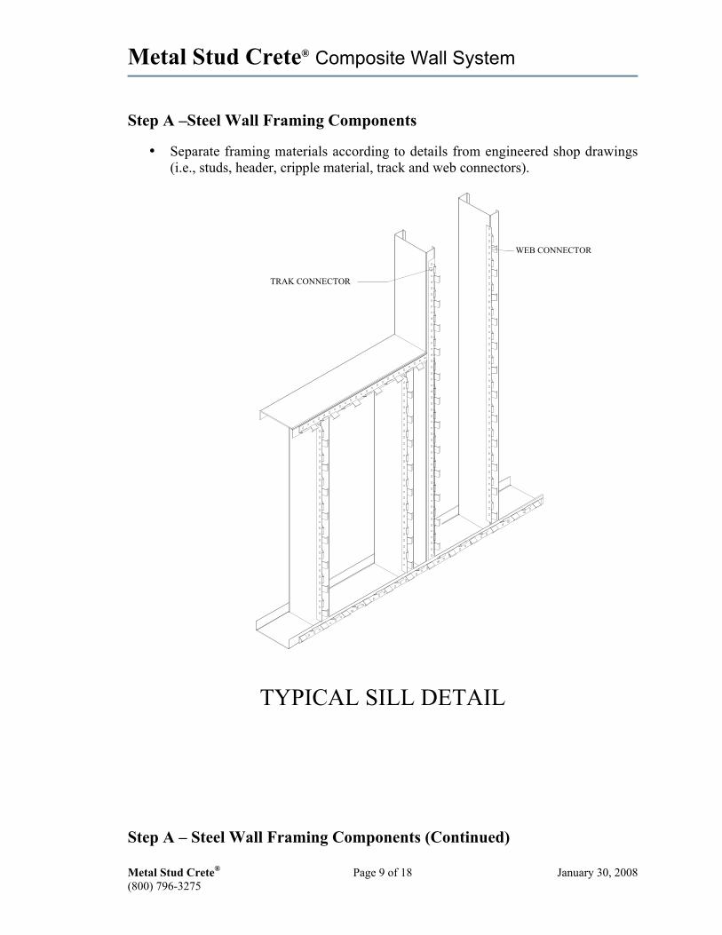
Step A –Steel Wall Framing Components
• Separate framing materials according to details from engineered shop drawings(i.e., studs, header, cripple material, track and web connectors).
WEB CONNECTOR
TRAK CONNECTOR
TYPICAL SILL DETAIL
Step A – Steel Wall Framing Components (Continued)
Metal Stud Crete® Composite Wall System
Metal Stud Crete® Page 10 of 18 January 30, 2008(800) 796-3275
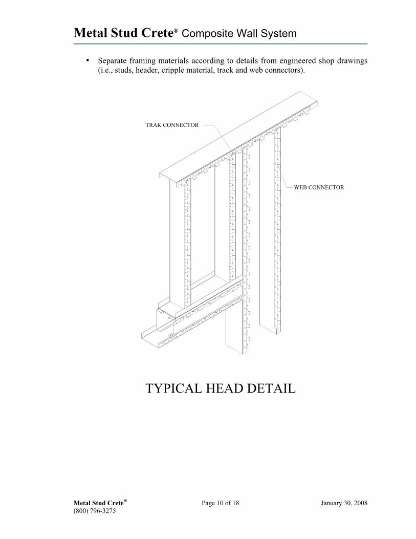
• Separate framing materials according to details from engineered shop drawings(i.e., studs, header, cripple material, track and web connectors).
WEB CONNECTOR
TRAK CONNECTOR
TYPICAL HEAD DETAIL

Metal Stud Crete® Composite Wall System
Metal Stud Crete® Page 11 of 18 January 30, 2008(800) 796-3275
Step B – MSC Strip Attachment
• Attach the appropriate MSC shear connectors to the studs, top and bottom tracks,headers, king studs and cripples. Attach MSC shear connectors with galvanizedself-drilling, self-tapping sheet metal screws in accordance with size, type andspacing as designed by the structural engineer. (Note: Screws must have a currentICBO approval and must meet the allowable capacity of Table 1 of ICBO ESReport No. 5446.)
NOTE: MSC web shear connectors are to be used on vertical field framing members(excluding end studs).MSC trak shear connectors are to be used on end studs, horizontal framing membersand framing members around openings (windows and doors, etc.).
Metal Stud Crete® Composite Wall System
Metal Stud Crete® Page 12 of 18 January 30, 2008(800) 796-3275
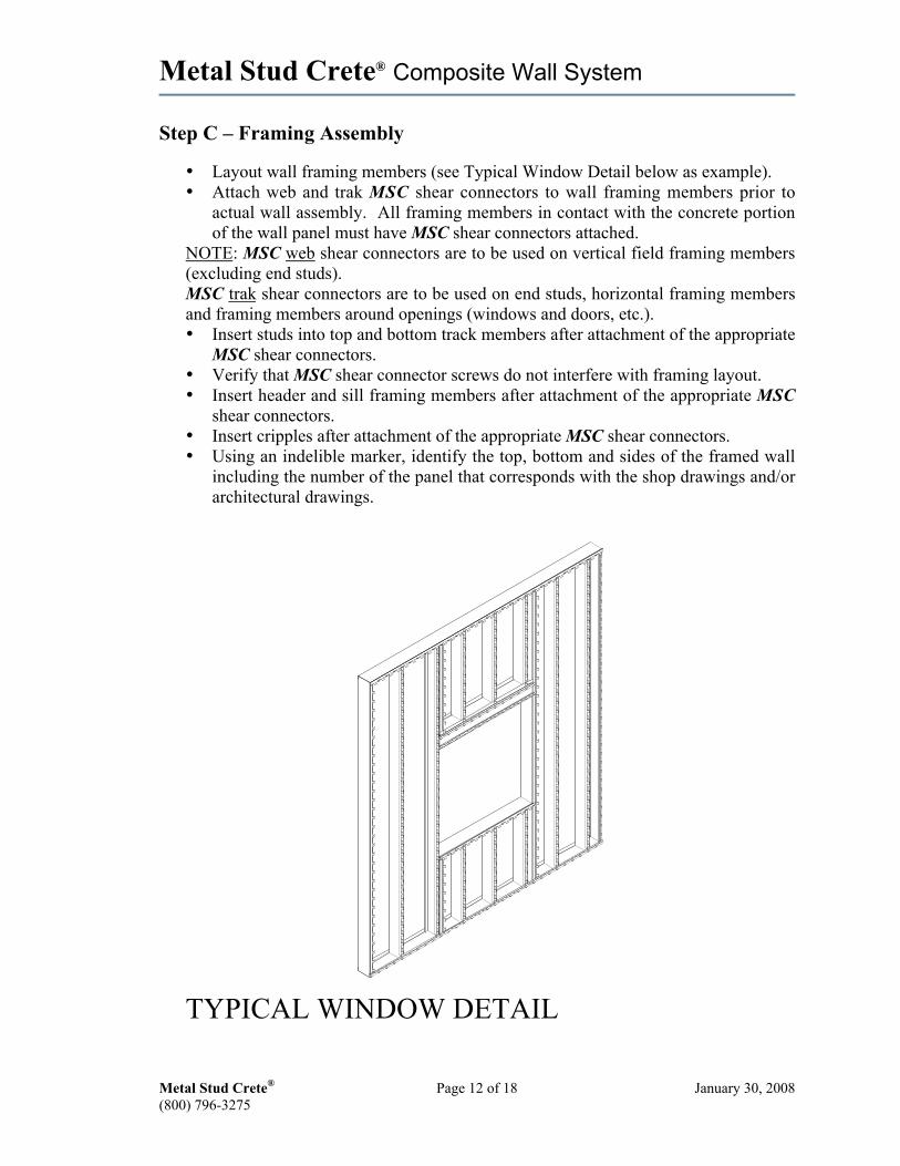
Step C – Framing Assembly
• Layout wall framing members (see Typical Window Detail below as example).• Attach web and trak MSC shear connectors to wall framing members prior to
actual wall assembly. All framing members in contact with the concrete portionof the wall panel must have MSC shear connectors attached.
NOTE: MSC web shear connectors are to be used on vertical field framing members(excluding end studs).MSC trak shear connectors are to be used on end studs, horizontal framing membersand framing members around openings (windows and doors, etc.).• Insert studs into top and bottom track members after attachment of the appropriate
MSC shear connectors.• Verify that MSC shear connector screws do not interfere with framing layout.• Insert header and sill framing members after attachment of the appropriate MSC
shear connectors.• Insert cripples after attachment of the appropriate MSC shear connectors.• Using an indelible marker, identify the top, bottom and sides of the framed wall
including the number of the panel that corresponds with the shop drawings and/orarchitectural drawings.
TYPICAL WINDOW DETAIL
Metal Stud Crete® Composite Wall System
Metal Stud Crete® Page 13 of 18 January 30, 2008(800) 796-3275
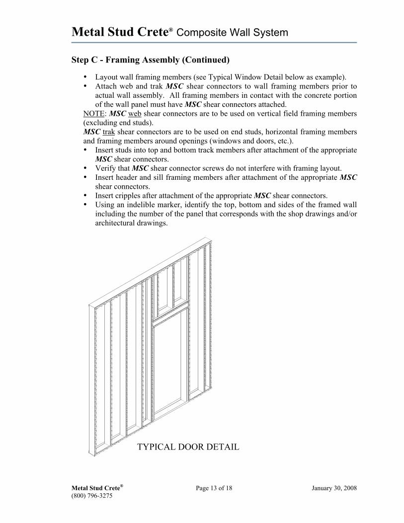
Step C - Framing Assembly (Continued)
• Layout wall framing members (see Typical Window Detail below as example).• Attach web and trak MSC shear connectors to wall framing members prior to
actual wall assembly. All framing members in contact with the concrete portionof the wall panel must have MSC shear connectors attached.
NOTE: MSC web shear connectors are to be used on vertical field framing members(excluding end studs).MSC trak shear connectors are to be used on end studs, horizontal framing membersand framing members around openings (windows and doors, etc.).• Insert studs into top and bottom track members after attachment of the appropriate
MSC shear connectors.• Verify that MSC shear connector screws do not interfere with framing layout.• Insert header and sill framing members after attachment of the appropriate MSC
shear connectors.• Insert cripples after attachment of the appropriate MSC shear connectors.• Using an indelible marker, identify the top, bottom and sides of the framed wall
including the number of the panel that corresponds with the shop drawings and/orarchitectural drawings.
TYPICAL DOOR DETAIL
Metal Stud Crete® Composite Wall System
Metal Stud Crete® Page 14 of 18 January 30, 2008(800) 796-3275
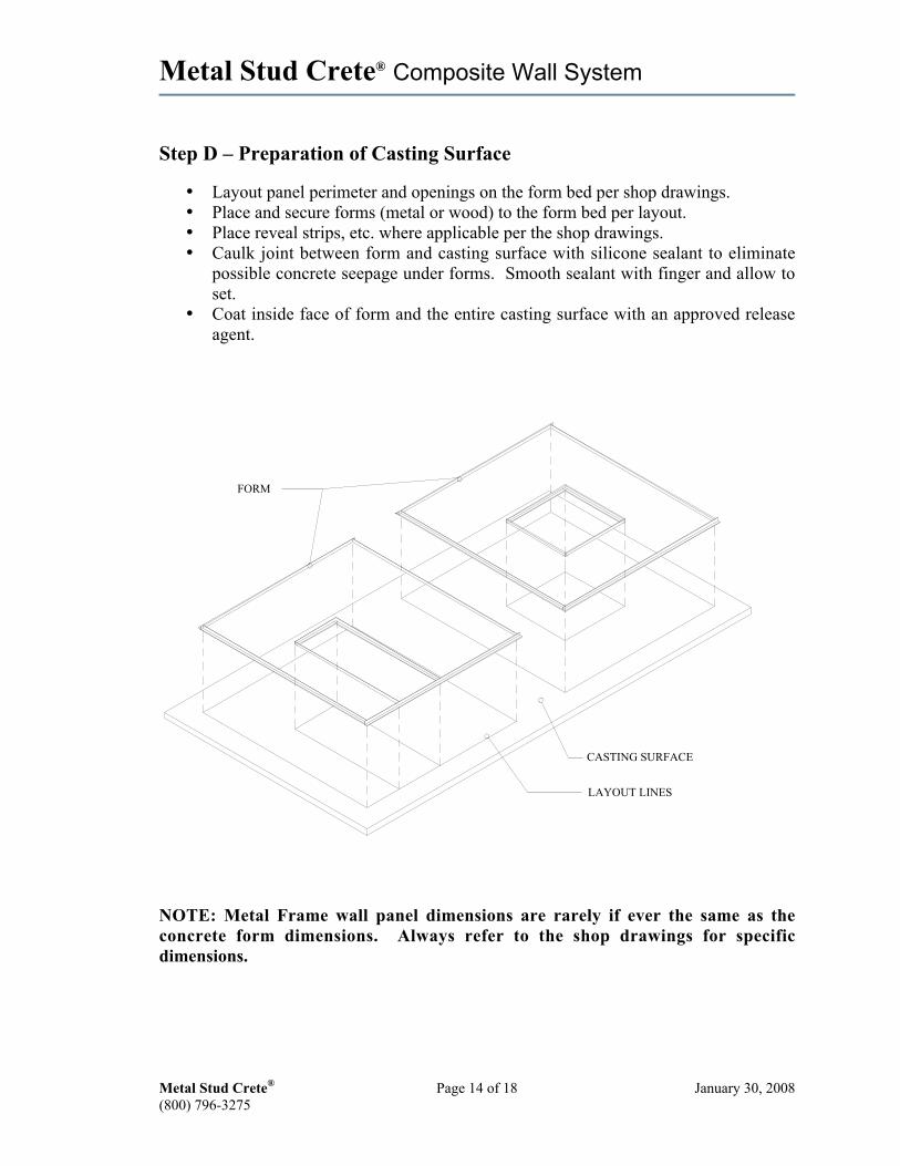
Step D – Preparation of Casting Surface
• Layout panel perimeter and openings on the form bed per shop drawings.• Place and secure forms (metal or wood) to the form bed per layout.• Place reveal strips, etc. where applicable per the shop drawings.• Caulk joint between form and casting surface with silicone sealant to eliminate
possible concrete seepage under forms. Smooth sealant with finger and allow toset.
• Coat inside face of form and the entire casting surface with an approved releaseagent.
FORM
CASTING SURFACE
LAYOUT LINES
NOTE: Metal Frame wall panel dimensions are rarely if ever the same as theconcrete form dimensions. Always refer to the shop drawings for specificdimensions.
Metal Stud Crete® Composite Wall System
Metal Stud Crete® Page 15 of 18 January 30, 2008(800) 796-3275
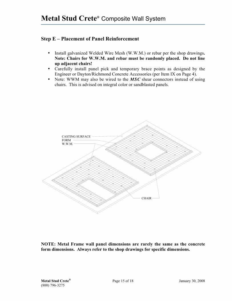
Step E – Placement of Panel Reinforcement
• Install galvanized Welded Wire Mesh (W.W.M.) or rebar per the shop drawings.Note: Chairs for W.W.M. and rebar must be randomly placed. Do not lineup adjacent chairs!
• Carefully install panel pick and temporary brace points as designed by theEngineer or Dayton/Richmond Concrete Accessories (per Item IX on Page 4).
• Note: WWM may also be wired to the MSC shear connectors instead of usingchairs. This is advised on integral color or sandblasted panels.
CASTING SURFACE
W.W.M.FORM
CHAIR
NOTE: Metal Frame wall panel dimensions are rarely the same as the concreteform dimensions. Always refer to the shop drawings for specific dimensions.
Metal Stud Crete® Composite Wall System
Metal Stud Crete® Page 16 of 18 January 30, 2008(800) 796-3275
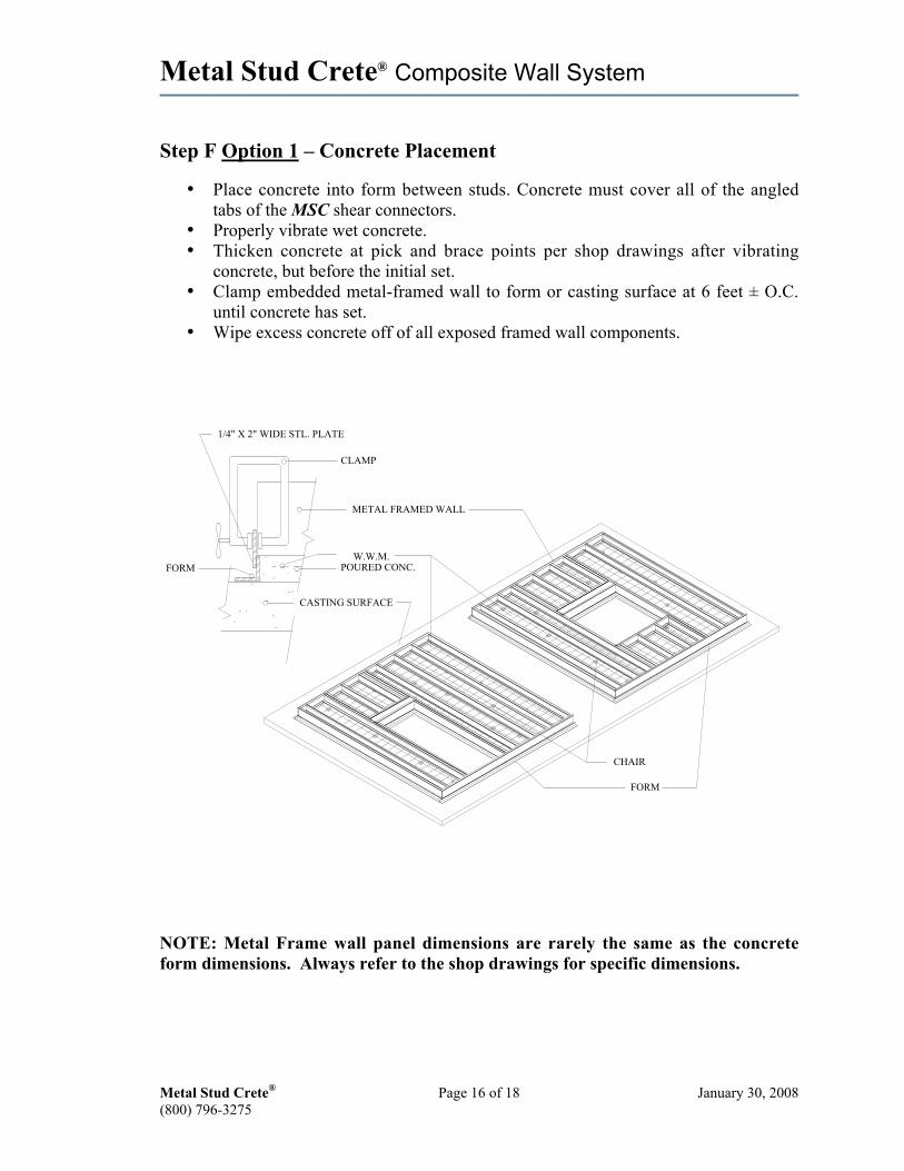
Step F Option 1 – Concrete Placement
• Place concrete into form between studs. Concrete must cover all of the angledtabs of the MSC shear connectors.
• Properly vibrate wet concrete.• Thicken concrete at pick and brace points per shop drawings after vibrating
concrete, but before the initial set.• Clamp embedded metal-framed wall to form or casting surface at 6 feet ± O.C.
until concrete has set.• Wipe excess concrete off of all exposed framed wall components.
CASTING SURFACE
FORM
W.W.M.
CHAIR
METAL FRAMED WALL
1/4" X 2" WIDE STL. PLATE
FORM
CLAMP
POURED CONC.
NOTE: Metal Frame wall panel dimensions are rarely the same as the concreteform dimensions. Always refer to the shop drawings for specific dimensions.
Metal Stud Crete® Composite Wall System
Metal Stud Crete® Page 17 of 18 January 30, 2008(800) 796-3275
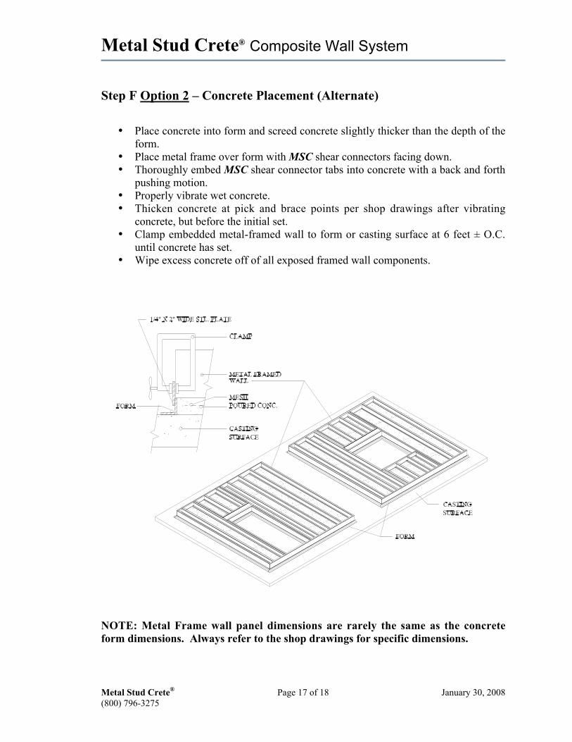
Step F Option 2 – Concrete Placement (Alternate)
• Place concrete into form and screed concrete slightly thicker than the depth of theform.
• Place metal frame over form with MSC shear connectors facing down.• Thoroughly embed MSC shear connector tabs into concrete with a back and forth
pushing motion.• Properly vibrate wet concrete.• Thicken concrete at pick and brace points per shop drawings after vibrating
concrete, but before the initial set.• Clamp embedded metal-framed wall to form or casting surface at 6 feet ± O.C.
until concrete has set.• Wipe excess concrete off of all exposed framed wall components.
NOTE: Metal Frame wall panel dimensions are rarely the same as the concreteform dimensions. Always refer to the shop drawings for specific dimensions.

Metal Stud Crete® Composite Wall System
Metal Stud Crete® Page 18 of 18 January 30, 2008(800) 796-3275
STEEL STUD FABRICATION AND CASTING PRODUCTION TIPS
SITE CAST OR PRECAST
Always order steel studs (-1/4" from the height dimension shown on shop drawings + 0").This will allow 1/8" for the thickness of the top and bottom track and 1/8" for the insideroll of the tracks. The vertical studs should then seat into the tracks and the outsideheight dimension of the panel should now be the same as the shop drawing height. MSCconnectors should be attached to the light gauge framing members before assembling thepanels.
The light gauge steel framing sits on the formwork around the perimeter of the panel.Allowing for the thickness of the formwork, the formwork should be set, to hold theconcrete back 1/4" from the outside edge of the framing, this will serve to create a 1/2"caulk joint between adjacent panels or the slab. It also serves to chair up the framingduring casting. Clamp down the frame to the formwork and also keep weight on theframe while the concrete is setting to keep the frame from riding up in the form. Onsmaller panels the concrete can be placed in the form first then the frame placed on top ofthe form. On larger panels it may be necessary to pump concrete between the stud baysto encapsulate the MSC connectors. Use SCC concrete or a 5 or 6 slump with a veryplastic mix and use 4,000 to 5,000 psi concrete with a very minimal vibration asaggregates tend to move away from the steel framing in a straight line when overlyvibrated. This over vibration causes a different texture on the surface, or an appearanceof a color variation or an outline of the framing or mesh, on the concrete surface when theconcrete is sandblasted. Adjust your concrete mix for temperature changes to avoidshrinkage cracks. Panels may need to be covered when exposed to high outsidetemperatures. If you have to vibrate; vibrate the framing from the top not the castingsurface, use stingers sparingly. Always lift the panels from the casting surface or truckbed horizontally (top and bottom pick points) before rotating the panel to the vertical pickpoints.
Contact your concrete supplier for the correct design mix to meet the current temperaturecondition, slump and curing requirements of this thin concrete section.
Metal Stud Crete®
6232 Santos Diaz StreetIrwindale, California 91702-3267
(800) 796-3275FAX (626) 334-6106
Metal Stud Crete® Composite Wall System
Metal Stud Crete® Page 19 of 18 January 30, 2008(800) 796-3275
STORING AND TRANSPORTING METAL STUD CRETE® PANELS
Sometimes it is necessary to store panels prior to erection at the job site. In all cases thegoal will be to prevent the thin concrete from bowing. New thin concrete prior tocomplete curing (usually 28 days) is very flexible and susceptible to temperaturechanges.
Storing MSC Panels at the Precast Yard:
It is best to keep the panels away from direct sunlight exposure on the face. This meansstoring the panels vertically with the concrete facing north to keep the east west sun offthe face, or cover the panels. Storing the panels vertically keeps the load on the steelstuds which are then in tension and will tend to keep the concrete from bowing.
Transporting Panels:
Any bowing accumulated from weather exposure during storing will disappear when thepanels are in transit and are loaded horizontally with dunnage placed between the panels.Any remaining bowing not removed from transporting the panels horizontally willdisappear when the panels are erected to the structure, or when they again have a verticalload on the studs.
Wooden dunnage 6" x 10" blocks placed on the concrete inside the steel stud bays at 4' or6' centers with a 2" x 6" board spanning the dunnage the width of the panels andextending at least 2" above the stud height is recommended.
When using a flatbed trailer to ship, place wooden 2' x 6' the width of the trailer at 4'centers under the first panels set on the trailer. Make sure the first panels placed on thetrailer are level, then proceed with the wooden dunnage on the second and third panels. Itis not recommended to stack more than 3 panels high. Panels may also be transportedvertically on a special A-frame or low boy trailer.
Plastic or cushioned protectors placed on top of the dunnage will protect the concretefrom marring. This is recommended especially on colored or textured panels with anarchitectural finish.
Storing Panels on Job Site:
Storing panels vertically is recommended, but if it is not practical then they may be storedhorizontally using the same method as described under Transporting Panels. Be sure thatsufficient dunnage is placed to keep the panel weight evenly distributed so as not to havethe ends of the panels unsupported. Select a level area on the job site to place wooden 2"x 6" boards at 4' centers and lay the first panel down so its weight is evenly distributed,then proceed with the dunnage placed between panels as described in TransportingPanels. Covering the panels may help to keep the sun off of the concrete surfaces. It'sthe change of temperature, heat to cold and back again, that causes the concrete to flex indifferent directions when the panels are not vertically loaded or attached to a structure.
Metal Stud Crete® Composite Wall System
Metal Stud Crete® Page 20 of 18 January 30, 2008(800) 796-3275
MSC PANEL ERECTION GUIDELINES
MSC panels may be erected on a concrete slab, footing, stem wall, concrete frame orsteel frame structure. Panels are always erected in the vertical position hanging from thetop picks.
When erecting panels on flat horizontal surfaces like a concrete slab, the critical elementis that the surface must be level to 1/8" in 10 feet. If there are high spots in the slab theseshould be ground level. Shimming, using tilt-up type shims, may be used to keep panelslevel. The first panel erected should be erected on the highest point then the other panelsshould be erected going out to either side from the first panel. If shims are required, itwill create a void under the panels that will have to be grouted solid.
Panels may be shimmed between panels or panels may be screwed together or notattached to each other at all depending on their final intended use, load bearing or nonload bearing (see engineering erection drawings). Care should be taken to plumb andalign panels so they are square at the top, as well as vertically square and that the studs onthe inside line up with the adjacent panels.
When erecting panels on to a steel or concrete frame super structure, there will beconnection hardware cast into beams on the inside of the MSC panels. This panelhardware will marry up to hardware already attached to the structure by others.Connection of the panel hardware to the structure will be by welding or bolting thecompanion pieces together (see engineer's erection drawings, detail sheet or individualpanel drawings for the type of connection hardware specified).
Metal Stud Crete® Composite Wall System
Metal Stud Crete® Page 21 of 18 January 30, 2008(800) 796-3275
Production Data
Precasters:
Project Name Fabricator’sName
Q. C. Agency
Reviewed and Approved: Date Reviewed:
By:_____________________ ______________CBSI
By:_____________________ ______________Fabricator
By:_____________________ ______________Quality Control Agency