metal properties and processes - langholm & canonbie ...€¦ · select the right one to suit a...
TRANSCRIPT

EXAM
REVISION Metal Properties and
Processes
Metals for the major portion of the earths elements.
They can be found combined with other elements as minerals which are mined in various ways.
Metal ‘ores’ are processed using different methods depending on the ore.
Gold is the only metal found in its pure state.
Other metals are found chemically combined with other elements in the form of oxides or sulphates.
Metals are categorised as Ferrous and Non-Ferrous.
Metals

These are mixtures of metals and/or other elements combined together.
Ferrous alloys range from plain carbon steels, with 98% iron, to high alloy steels, with up to 50% of other elements.
All other metals are non-ferrous and can be subdivided into light, heavy and refractory (heat resistant) alloys.
Ferrous alloys, particularly steels, form 90% of the world’s total metal usage. This is because of their low cost and versatility which is brought about hardening and tempering.
Alloys

Elasticity Ability to return to shape after deformation.
Toughness Ability to withstand sudden loading (impact resistant).
Brittleness Ability to be snapped easily.
Malleability Ability to be hammered into shape without fracturing.
Hardness Resistance to wear or indentation
Ductility Ability to be stretched (drawn) to a reduced cross-section.
Properties

Ferrous Metals Take a note

Iron is the basis of ALL ferrous alloys. Pure iron is of little practical use as a material. Ferrous metals all contain iron and in addition will contain other elements in varying quantities. The principle element which is mixed with IRON is CARBON. The percentage of carbon which is added to the iron will produce alloys of varying properties
It is important to know the properties of the various grades of steel so that you can select the right one to suit a particular application and method of manufacture.
Steel (alloy of iron and carbon) with a low carbon content will tend to be quite soft e.g. Black bar. Steel with a high carbon content will tend to be very hard and brittle e.g. tool steel
Cutting Tools
Car Bodies
Ferrous Metals

These metals contain Iron!
Name Composition Properties and Working
Characteristic
Uses
Cast Iron Iron+3.5% Carbon Brittle/Hard skin Machine Tools,
vices
Mild Steel Iron+0.35% Carbon Malleable/ductile,
uniform texture
Nuts, bolts, screws,
tubes, grinders, car
bodies
High Carbon
Steel
Iron+ up to 1.5%
Carbon
Malleable/ductile, can
be hardened or
tempered.
Cutting knives,
files, drills, saws,
knives, hammers,
taps and dies

Non-Ferrous Metals
Take a note

The group of metals does not contain iron and therefore will withstand moist
conditions. Common examples are:
-copper, aluminium, tin and lead
-precious metals such as gold and silver
-metals used in small amounts (mercury, platinum, chromium)
-’new’ metals (vanadium, niobium, zircoium).
Aluminium
Aluminium is the Earth’s most plentiful metal. Aluminium’s lightness and strength make it
the most widely used non-ferrous.
Other Non-ferrous Alloys
Other common non-ferrous alloys include:
-brass (copper and zinc)
-bronze (cooper and tin)
-soft solders (lead and tin)
Non-Ferrous Metals

Name Composition Properties andworkingcharacteristics
Uses
Aluminium Pure metalproduced
Good strength toweight ratio, castseasily
Window frames,pots and pans
Copper Pure metal Ductile/malleable,low melting point,expensive
Central heatingpipes, electricwiring/cable,jewellery
Tin Pure metal Heavy/soft, lowmelting point
Bearings, solder,coating sheet steel
Lead Pure metal Heavy/soft/weak,ductile/malleable,low melting point,can be cast
Roof flashing,solder
Zinc Pure metal Weak, difficult towork
Galvanising
Non-Ferrous Metals Take a note

Metal Processes Take a note

Metal Turning Take a note
https://www.youtube.com/watch?v=7LMOml
y7zfg

Turning is the production of cylindrical components using a centre lathe. The
material is held firmly in a rotating chuck whilst a cutting tool is brought towards
it to create the required shape. A variety of processes can be carried out on
the lathe for example turning cylinders, creating texture (knurling), accurate
drilling and threading
Turning

Milling Take a note

Milling machines are powerful pieces of equipment which use rotating multi
toothed cutters to shape the material. There are two types of milling machine,
horizontal and vertical. The machines are named by the position of the cutting
tool in relation to the workpiece. Milling machines can be used as side and
face cutters and can also be used to cut slots in the material.
Milling consists of machining metal by using rotating cutters which have a
number of cutting edges. These tools are known as milling cutters.
Horizontal Milling Machine Vertical Milling Machine
Milling
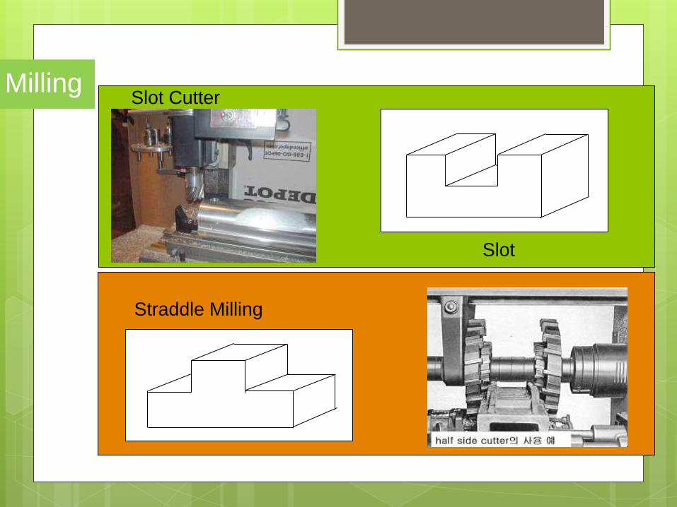
Slot Cutter
Slot
Straddle Milling
Milling

Dovetail Slot
Dovetail Cutter
Angle Cutter
Angled Face
Milling

Flat Surface
Slab Cutter
T-Slot
Tee Slot Cutter
Milling

Die Casting
https://www.youtube.com/watch?v=LH8B3i6
e8d4
Take a note

Where large quantities of quality castings are required in industry, the moulds
(‘dies’)need to be permanent. These special, alloy moulds are costly to produce
because they are made in sections for easy removal of the components. The high
operating costs involved make this process economically viable for high volume
mass production where accuracy of shape, size and surface finish is essential.
Gravity Castings
Molten metal is poured into the cavity under its own weight. This produces sound,
dense castings with mechanical properties superior to pressure casting (since metal
enters the mould with less turbulence). This process also traps less gas than
pressure casting does, leading to less porosity.
Die Casting
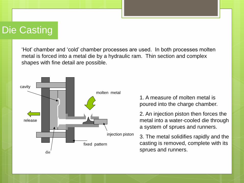
die
fixed pattern
injection piston
molten metal
release
cavity
‘Hot’ chamber and ‘cold’ chamber processes are used. In both processes molten
metal is forced into a metal die by a hydraulic ram. Thin section and complex
shapes with fine detail are possible.
1. A measure of molten metal is
poured into the charge chamber.
2. An injection piston then forces the
metal into a water-cooled die through
a system of sprues and runners.
3. The metal solidifies rapidly and the
casting is removed, complete with its
sprues and runners.
Die Casting

Materials
Materials used in this process include low melting temperature alloys, lead, zinc,
aluminium and brass alloys.
Identifying Features
Section hair lines, ejector pin marks, flashes caused by leakage left on internal
surfaces (these do not interfere with performance or appearance), and sprue and
runner marks.
Die Casting

Press Forming Take a note

Press forming involves squeezing sheet metal between two matched metal moulds
(dies). This gives a very strong, shell-like structure. One die is the mirror image of
the other, apart from an allowance for he thickness of the material being formed.
The machining of these dies is a specialised skill. They can be complicated and
therefore difficult and time consuming to make. This makes them very expensive to
produce.
The Process
The sheet metal component starts out as a flat sheet or strip
1 A blank is cut to the required size.
2 The blank is placed in a press.
3 The product is formed using immense force.
The complete forming process may take several additional stages of
operations to form, draw (stretch) and pierce the material into its final shape
Press Forming

Materials
Sheet metals; various steels, aluminium alloys, brass, copper
Identifying Features
Sudden directional changes, i.e. sharp edges and deep draws, are avoided to minimise
overstretching the walls of the product. Different operations, e.g flanges, ribs, piercing,
can be identified.
Uses
Products used in many everyday activities are easily identifiable. These range from pans,
kettles and stainless steel kitchen sinks to car bodies and aircraft panels.
Press Forming

Sand Casting Take a note

Sand casting is the most frequently used metal casting process. ‘Green, foundry
sand is a blend of silica grains, clay and water. The term ‘green’ describes the
damp quality which bonds the sand together. Oil-bound sand gives excellent
results but is relatively expensive and difficult to reconstitute. There is an
element of waste involved as the sand that is in contact with the hot metal will
burn. This burned sand needs to be scraped out and disposed of.
The quality of the casting produced depends on the quality of the pattern. These
are normally made in wood. The pattern requires radiused corners, drafted
sides and a good surface finish. The sand mould is produced around the
pattern, which is removed to leave a cavity. Molten metal is poured into the
mould and solidifies. When cold, the mould is broken up to retrieve the casting.
Sand Casting

pattern
sprue pins
cope
drag
gates
riser runner
1. Place the pattern centrally in the drag.
2. Pack sand around the pattern.
3. Turn the drag over and attach the cope.
4. Insert sprue pins and pack sand around them.
5. Remove the sprue pins.
6. Split the moulding box and cut ‘gates’.
7. Remove the pattern to leave a cavity.
8. Reassemble the cope so that the mould is ready to receive the molten metal.
9. Pour the molten metal into the runner. The melt fills the mould and exits, along with
any gases, via the riser.
Sand Casting

Materials
Iron, aluminium and non-ferrous alloys are most widely used in sand casting. Exceptions
include refractory (able to withstand high temperatures) metals such as titanium. Precious
metals e.g. gold lend themselves to casting.
Identifying Features
Complex 3-D components. Mainly solid but internal shapes can be produced using cores.
Thin sections are difficult to mould. Surface texture can be poor. Draft angles, fillets,
rounded corners and strengthening webs will be evident and will echo the pattern
requirements. Other recognisable features include bosses and porous surface textures.
Fettle marks, due to the removal of runners and risers, may be visible.
Uses
Casting is a versatile process using the material properties in the manufacture of engine
parts, tools and decorative jewellery. Multiple mould patterns decrease production time
thus lowering production costs.
Sand Casting

Casting in Aluminium
The main reason for casting an object is that the shape of the object is such
that it would make matching either very difficult or too expensive.
There are many ways in which an object can be cast, but there are only two
ways which are suitable for use in the school workshop.
1. Gravity feed casting
2. Investment casting.
The main difference being that gravity feed casting uses a wooden pattern
and so can be used for large numbers, where as investment casting uses
either a wax or a polystyrene pattern and therefore only be used once. Both
these methods come into the category of Green sand moulding, which gets
its name not from the colour of the sand, but because the sand is damp.
Casting

Piercing and
Blanking Take a note

Piercing and blanking are essentially the same process, involving the stamping of
shapes out of sheet metal or metal strip. The differences in the process simply
depend on which bit of metal is to be kept: in piercing a shaped hole is made in the
metal, whereas in blanking a shape is stamped out of the metal and then used.
The Process
punch
strip
die
Piercing
The punch and die are shown here
in the closed position. Notice how
the punch fits into the die but does
not enter it, stopping instead as
soon as the metal has been cut.
Accurate alignment of the two is
essential.
Piercing and Blanking

Blanking
The main components used for blanking in
mass production are a punch, a die and a
stripper plate. The stripper plate prevents
the metal ‘riding up’ the die on its upward
travel. The die is attached to the main press
by means of a bolster plate. The punch is
attached to a movable ram.
Blank falling through die
and bolster plate
Bolster plate
Die
Ram
Metal Strip
Punch
Stripper
Piercing and Blanking
The Process

Progressive Piercing and Blanking
Many products requires to be both pierced and blanked.
This is often done in the same press by first piercing the
metal, and then moving it along to another die and
blanking out the desired shape. This process is called
progressive piercing and blanking.
1 The metal strip is fed into the first die.
2 A hole is pierced in the metal on the first stroke of the
ram.
3 The ram rises and metal is moved into position over
the blanking die.
4 Accurate alignment is essential here.
5 The punch descends and the completed component (
in this case a washer) is blanked from the metal strip. At
the same time a hole is pierced in the next washer.
6 Piercing is normally done before blanking, as this
minimises the risk of fracturing the metal.
Metal Strip Finished Washer
Metal Strip
Stripper
Piercing punch
Die
Stop
Scrap
Ram
Blanking
punch
Pilot
Progressive Piercing and Blanking
The Process

Materials
Most types of metals can be pierced and blanked in sheet or strip form. The metal is
normally annealed first so as to minimise the risk of fracture or tearing.
Identifying Features
A sheared surface will show two distinct areas of deformation and fracture. With the
correct clearance angles in the punch, this can be minimised to give a reasonably smooth
edge which will require no further finishing.
Uses
Uses of piercing and blanking include component parts for a variety of tool and products.
Often products made from sheet metal that have been press formed are pierced to give a
decorative finish.
Piercing and Blanking

Drop Forging Take a note

Impression-die drop forging is an industrial process used in the production of high quality, strong metal components or products. The main advantages are that components can be accurately repeated using specially shaped dies to control the flow of metal; the need for highly skilled craftsmen is thus eliminated.
PR
ES
SU
RE
PR
ES
SU
RE
Anvil
Ram
Top Die
Bottom Die
Billet Flash
The Process The die used are very expensive to produce. High alloy steels are required to prevent heat loss
which causes them to wear too quickly under impact loads.
1. A hot metal billet is placed between the
dies.
2. The hot metal is forced into the cavity
using a power driven hammer. (Note that the
process may take more than one operation using a
succession of dies.)
3.Excess metal is squeezed out forming a
flashing around the parting line of the two
dies. The amount of flashing is determined
by die wear and the quantity of excess
metal.
4. When the forging is complete the flash is
removed using a trimming die.
Drop Forging

Materials Most metals are in alloy form are suited to the drop forging process. Alloy steels and copper alloys are most
common.
Identifying Features The function of the product may indicate that drop forging is the most appropriate process for manufacture, i.e. the
product or certain parts of the product may require compressive or tensile force to be used. Strength to weight
ratio is a consideration. Visually there may well be evidence of flashing and flash removal around the edges of
the product. Quality products may have undergone further finishing to eliminate visual evidence of die parting
lines.
Uses Drop forging metal increases its strength. The grain structure of the metal is changed to follow the outer contour of
the component. This provides greater scope for the design of high quality metal products. Examples range from
hand tools such as spanners and plumbing fittings to high quality cutlery and domestic appliances.
Drop Forging

Joining Materials Take a note

The manufacture of most products requires joining together of materials. Part
of the designer’s role is to select the most appropriate method.
Permanent joining methods include adhesives, arc welding, fitted joints,
riveting, spot welding.
Non-permanent methods include nuts, bolts and screws.
Joining Materials

Mechanical knock down fixings are generally used on square cut butt joints on
manufactured boards. No glue is required but accurately drilled holes are essential.
Knock-down fixings (fixings) make assembly straight forward and have the added
advantage that dismantling a product is possible.
PLASTIC CORNER
BLOCK
TWO BLOCK
FITTING
RIGID JOINT
Joining Materials Knock-down Fittings

Knock-down fittings are those that can be put together easily, normally using only a
screw driver, a drill, a mallet/hammer and other basic tools. They are temporary
joints although many are used to permanently join together items such as cabinets
and other pieces of furniture that are purchased in a flat pack
CAM LOCKS
SCAN FITTINGS
Joining Materials
Knock-down Fittings

Soldering, brazing and welding techniques are used mainly to join metals. Some
thermoplastics can also be joined in this way.
Arc Welding
Heat is obtained by an electric arc via a transformer. One lead is attached to the work
and the other to a grip holder a welding rod. An arc is formed when the end of the
rod is brought near the work. The heat melts the parent metal and the filler rod
together. The rod is coated with flux to prevent oxidation.
Joining Materials Welding

The metal is heated and fused together between two copper electrodes. Used on thin
gauge mild steel, e.g. car bodies
Joining Materials Spot Welding

There are two methods. The traditional method uses soft iron, aluminium or copper for
snap, countersunk and flat head rivets in conjunction with a hammer and rivet ‘set’.
1
.
2
. 3
.
4
.
5
.
Joining Materials Riveting

Where the use of a hammer is to be avoided, controlled pressure is applied to a ‘pop
rivet’ using a pop-riveting ‘gun’. Also used for ‘blind’ riveting.
1. 2. 3.
The two pieces of
plastic or aluminium
are drilled to a size
slightly larger than the
rivet
The pop rivet is passed
through both holes in the
sheet plastic /
aluminium.
The rivet pliers are pushed on to the pin of the
rivet and the handles are pulled together. As
this happens the pin head is pulled into the
rivet and the end of the rivet is expanded.
Eventually the pin will break off leaving the
rivet permanently fixed in position holding the
two pieces of plastic / aluminium together.
Joining Materials Pop Riveting

The screw thread has the advantage of enabling items to be taken apart for inspection
or maintenance purposes. Nuts, bolts and set screws can be obtained in various
forms. There are numerous designs of spanners for use with square- and
hexagonal-headed nuts and bolts, just as there are keys for socket screws.
Joining Materials Bolts

Screws are used to fasten together boards, panels and fittings such as hinges and
brackets. Pieces can be taken apart and reassembled without damage. Screwdrivers
are available in a variety of blade types, e.g. slot and pozidrive. Effort in driving screws
home can be minimised by using electrically powered ‘screw guns’
Joining Materials Screws