metal fingerstock - frd
TRANSCRIPT

EMI SHIELDING SOLUTIONS
METAL FINGERSTOCK

ISO 9001 ISO 14001 QC 080000 OHSAS 18001 ISO/TS 16949 UL CSA
Company Overview
Established in Shenzhen, China, in 1993, FRD manufactures a wide
range of products including EMI Shielding Materials, Thermal Interface
Materials and other related electronic materials. FRD is a registered
National Hi-Tech Enterprise and certificate of ISO9001, ISO14001,
QC080000 and OHSAS18001.
FRD works to satisfy the needs of its customers and we excels in
speed and flexibility. FRD has long-term business relationships with
customers such as Huawei, ZTE, Cisco, Nokia, Alcatel-Lucent, Juniper,
Dell, H3C, Microsoft, Lenovo, Xiaomi, Samsung, Foxconn, Flextronics,
Jabil, PEGATRON, SANMINA-SCI, O-Film Emerson, GREE, BYD, FUJI
XEROX, TOSHIBA, etc.
As a leading manufacturer in its industry, FRD is growing
tremendously. We are willing to provide quality products and services
for more customers in various industries than our competition.
These industries include networks & telecommunication equipment,
consumer electronics, automotive, power supplies, lighting, military,
aerospace, etc.
In future, FRD will continue to meet the challenge, to grow the FRD
brand name, and to strive to become a world-class technology leader
in new materials for all of our manufacturing processes.
New South China BaseShenzhen Guangming FRD New Materials Park
North China BaseTianjin FRD Science & Technology Co.,Ltd.
East China BaseKunshan FRD Electronic Materials Co.,Ltd.
FRD Building (Shenzhen)

1
Metal Fingerstock FRD
CONTENTS
Introduction 4
Applications and Features 5
Beryllium Copper 5
Mounting Options 6
Galvanic Compatibility Design 8
The appropriate choice of Force, Compression and Resistance 9
Shielding Effectiveness 10
Part Number System 11
Slot Mounting Series 12
Clip-on Mounting Series 15
Track Mounting Series 20
PSA Mounting Series 22
Contact Series 25
Metal Fingerstock Products 27
Note 28


Metal Fingerstock

4
Metal FingerstockFRD
FRD ® Metal Fingerstock
FRD’s EMI metal shielding products are suitable for a wide range of electronic devices which have EMI/RFI or
ESD problems. There are many kinds of products with different profile and dimension. Most of products are made
by beryllium copper, phosphor-bronze and stainless steel. The superiorities of metal shielding products are shown
as the following:
ʌ EMI metal shielding products will not burn, without influence of ray, ultraviolet radiation or ozone.
They not only solve the tangential slip joint problems of other gasket materials, but also have excellent
shielding performance over a broad band of frequencies.
ʌ Excellent elasticity and reusability
ʌ Excellentmechanical property, Suitable for a variety of applications
ʌ EMI metal shielding products can work well in many kinds of environments (e.g. high temperature),
having different plating to guarantee the compatibility with other contact surface.
ʌ Little joint pressure, light weight, sundry installation mode
ʌ Excellent thermal conductivity, pressure resistance, wearing resistance and plasticity
Therefore, incommunication equipments, computers, portableelectronic devices, medical instruments and
military equipments field, most engineer use metal finger stock as the ideal EMI shielding materials.
In addition, a wide range of product types and diverse installation can be used for a variety of shielded room/
door/cabinet doors/cover/printed circuit board(PCB)/integrated circuits shielding.
EMI metal shielding products can be well used in many occasionsfrom small handheld devices to large
shielding room which the shielding material needs to sliding friction and can be installed on the top or side of the
shielding.

5
Metal Fingerstock FRD
Applications and Features
Beryllium Copper
FRD's EMI metal shielding products are suitable for a wide range of electronic devices which have EMI / RFI or
ESD problems.
► A wide range of product types and diverse installation can be used for a variety of shielded room/door/cabinet doors/cover/printed
circuit board(PCB)/integrated circuits shielding.
► Can be well used in many occa sions which the shielding material needs to sliding friction and can be installed on the top or side
of the shielding.
► Applied from small handheld devices to large shielding room.
Beryllium copper(BeCu) is a high-performance metal, it can be cast and used in a wide range of part field. Its mechanical and electrical
properties make it to be an ideal shielding materials resistant to electromagnetic and radio frequency interference.
The electrical characteristics of beryllium copper provides a shielding effect in a wide range of frequency. Meanwhile, it’s superior
mechanical properties such as maximum flexibility and fatigue resistance make it have a long life cycle. In addition, BeCu has excellent
conductivity and different plating. Therefore, it used as the best material in shielding area.
Beryllium Copper SpecificationsChemical Composition
Be 1.80-2.00%
Co + Ni 0.20% (Min.)
Co + Ni + Fe 0.60% (Max.)
Cu Remainder
General plating thickness About 2.6μm (including no rare metals)
Physical Characteristics
Electrical conductivity (% IACS) 22-25
Elastic Modulus (psi) 18.5x10⁶
Mechanical properties (after heat treatment)
Temper grade 1/4 HT 1/2 HT HT
Tensile strength (kgf/m2) 123 (Min.) 130 (Min.) 133 (Min.)
Yield strength (kgf/m2) 105 (Min.) 112 (Min.) 116 (Min.)
Hardness range (HV) 350-430 360-440 380-450
ʌ Excellent elastic recovery
ʌ Low compression force, can bear bidirectional
compression
ʌ Persistent fatigueresistance
ʌ Does not exist stress relaxation phenomenon, with
stable size
ʌ Material properties is almost free from the rounded
corners and the rolling direction
ʌ Easily processed and into many shapes
ʌ Easily designed to miniaturization
ʌ Suitable for larger gap fill
ʌ Easy to install, having a variety of installation methods
ʌ Easy to plating and welding
ʌ Excellent conductivity
ʌ Ultra-low permeability
ʌ A wide range of temperature-change adaptation
ʌ Incombustible material
ʌ Corrosion-resistant
ʌ Excellent shielding efficacy
6
Metal FingerstockFRD
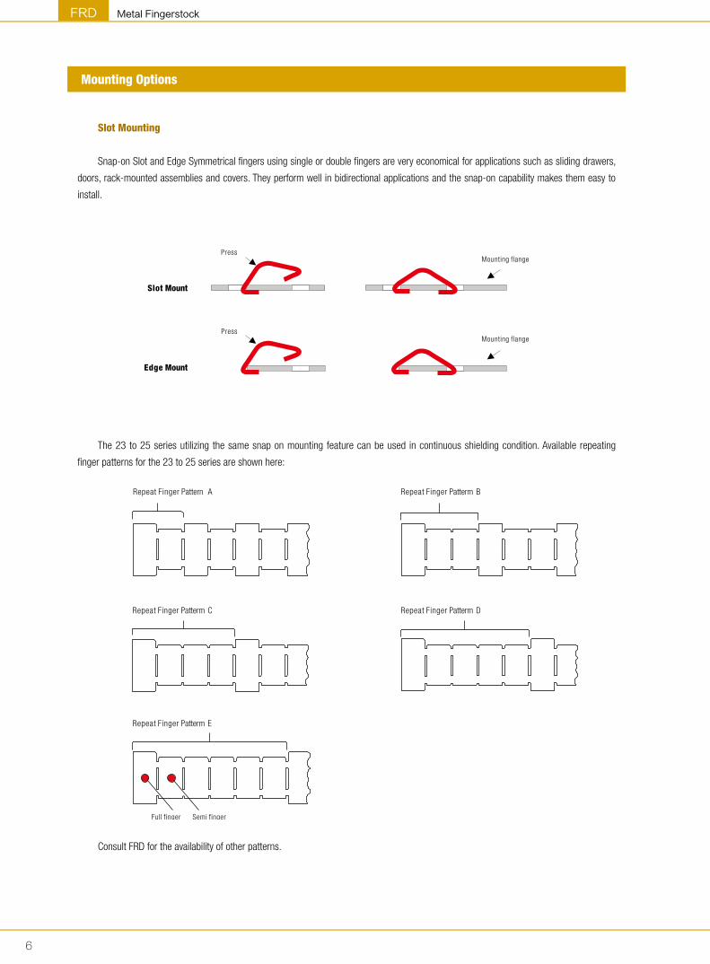
Mounting Options
Slot Mounting
Snap-on Slot and Edge Symmetrical fingers using single or double fingers are very economical for applications such as sliding drawers,
doors, rack-mounted assemblies and covers. They perform well in bidirectional applications and the snap-on capability makes them easy to
install.
The 23 to 25 series utilizing the same snap on mounting feature can be used in continuous shielding condition. Available repeating
finger patterns for the 23 to 25 series are shown here:
Consult FRD for the availability of other patterns.
Slot Mount
PressMounting flange
Edge Mount
PressMounting flange
Repeat Finger Patterm E
Repeat Finger Patterm DRepeat Finger Patterm C
Repeat Finger Patterm BRepeat Finger Pattern A
Semi fingerFull finger

7
Metal Fingerstock FRD
PSA Mounting
Pressure Sensitive Mounting provides double-sided pressure sensitive transfer tape for a fast, reliable installation, 3M 467 transfer tape
or equivalent may be used at ambient temperature from -55 to 230℃ . Apply only on a clean, oil-free surface, and allow a 24-hour cure
time. Please consult our engineer to provide other sticky tapes and expanded products.Hook and viscous fingers are low pressure and small-
gap shield the edges of an ideal material for applications.
Hook and stick fingers are ideal for flange mounting applications requiring low compression forces and small gap shielding.
Spider gaskets, featuring a continuous, smooth web of fingers on each side, are available in both PSA and Hook & PSA mounting
configurations. Non-conductive 0.25mm thick adhesive may be specified for improved adhesion on rough surfaces. Conductive adhesives are
also available.
Clip-on Mounting
Clip-on Mounting provides a reliable mechanical installation by the friction between shielding materials and structures. Meanwhile, “D”-
shape and “T”-shape lance can be incorporated to enhance the holding force. Some barbed-bit installation location or installation of thickness
may be different from your existing structure, please contact our engineering staff to determine changes.
Certain clip-on strips have lance locations or plate thickness other than shown above. Consult our engineer to determine the specific
dimensions.
"T"-shaped barb "D”-shaped barb
PSA gasket
Double adhesive transfer tape
1.5mm(max)Hook and PSA gasket
Hooks over FlangePSA

8
Metal FingerstockFRD
Track Mounting
The following are two ways to provide track:
ʌ By the risings and fallings of the structure itself
ʌ By adding other material to the structure
Special Mounting
Special mounting shielding strips can be installed by spot welding or soldering. Rivets and conductive pressure adhesives are also
available.
Galvanic Compatibility Design
Materials in adjacent groups may be safely used together in order to avoid the influence between the base material and the electroplated
layer. The materials chose from the same group provide better resistance to corrosion. For example, since BeCu is in group III, so it’s safe to
choose the material in group II, III & IV to use together.
FRD EMI metal shield products for more than 20 variety of plating layer, in order to ensure compatibility with the substrate
electrochemical specific please consult our engineering department.
Grouping of Metals by Decreasing Galvanic ActivityI II III IV
Mg Al Chrome Plating Brass
Magnesium Alloys Aluminum Alloys Carbon Steel Stainless Steel
Al Zinc/Zinc plating Steel Be Cu
Aluminum Alloys Chromium Plating Ni/ Nickel Plating Cu/Copper Alloy
Zinc/Zinc plating Cadmium Plating Sn/Tin plating Ni/ Copper Alloy
Chromium Plating Carbon steel Sn/Lead solder Monel
Cu Pb Ag
Ni/ Nickel Plat ing Brass Graphite
Sn/Tin plating Stainless Steel Rh
Sn/Lead solder BeCu Ti
Cu/Copper Alloy Pt
Ni/Copper Alloy Au
Three-step Installation
PressdownRivet
Press Down
0.5-1.5mmFlangeTrack
1.
The plastic rivet pressed into the flange
2.
The magnetic track finger foot hooks
3.
Finger pressed down to fasten magnetic track

9
Metal Fingerstock FRD
The appropriate choice of Force, Compression and Resistance
Compression
The purpose of shielding is to shade the clearance between two conjoint surface. The shielding materials must take up the maximal and
minimal gap to make itself effectively. The clearance exists due to the manufacturing tolerance, irregular surface and arraying, so appropriate
compression can provide the shielding of electromagnetic interference.
At the maximum gap the gasket should be compressed approximately 25%. Gaskets may be compressed to 50% of the height or more.
The following figure shows that the compression resistant is small and steady with the compression ratio between 15% to 60%.
Meanwhile, the compression is small comparatively. That is the reason we often suggest the compression ratio be about 30%.
min.
Installation side
Non-contact (no compression) Min. compression
The min. gapNormal gap
Normal compression Max. compression
Manufacturing Tolerance
Uneven surface
Irregular surface
gap max.
Operating range = the max. gap - the min. gap
Closed side
Height
max.
max.
min.
min.
gap
gap
The max. gap
FRD #3 3 samples( )
0
0.02
0.04
0.06
0.08
0.1
0.12
0.14
0.16
0.18
0.2
0% 8% 16% 24% 32% 40% 48% 56% 64% 72% 80%
0
1
2
3
4
5
6
7
8
9
Compression
Resi
stan
ceoh
min
ch(
/)
Forc
elb
inch
(/
)

10
Metal FingerstockFRD
Shielding Effectiveness
Attenuation
For maximum attenuation of a gasket gap, the contact resistance of the mounting joint and closing joint must be very low and remain so
throughout the life of the product. While a gasket may have the potential for very high attenuation under ideal conditions, over time oxidation,
corrosion and dirt at the mounting and closing joints may reduce effectiveness.
Factors influencing contact resistant are pressure(closing pressure), plating and wiping action. Our engineer can help you determine the
optimal specifications to ensure sustained attenuation.
The test result best embodies the shielding characteristics. However, many factors such as specifications, tolerance, spacing,
electroplated layer, installation and the rigidity of cover boards may cause measurement error even in the same standard of MIL-DTL-83528
or SAE ARP 1705.
FRD engineering team has rich experience in analyzing and improving the shielding effectiveness of materials and complete appliances
together with customers. Contact us if having some doubts in this respect.
The following are the test results of our typical shielding products.
If the standard series are still unable to fully meet your
requirements, please contact the engineering staff to confirm the
following information:
• Products may be using the machine the desired frequency
band and the value of shielding effectiveness
ʌ Material selection and characteristic parameters
ʌ Structural parts can be set aside for the design of the
cushioning material gap value
ʌ Whether particular compression force and Plug Power
requirements
ʌ Lining force forms and expectations of installation
ʌ Structural parts can be reserved for the other direction of
the cushioning material installation space or hole location
and other requirements
ʌ With regard to the requirements of pressure-sensitive
adhesive (For Use)
ʌ The choice of coating
ʌ The use of special occasions and environmental
requirements
ʌ A special packaging (eg, SMT) and follow-up of production
installation requirements
ʌ Other special requirements
1. The shielding effectiveness of 1-58E0-06096 sample compressed to a thickness of 0.5mm
shie
ldin
g ef
fect
ivene
ss/d
B
30 50 80 100 160 180 200 300 400 500 600 700 800 900 1000
f/MHZ
0
20
40
60
80
100
120
2. The shielding effectiveness of 1-73A2-03430 sample
shie
ldin
g ef
fect
ivene
ss/d
B
30 50 80 100 160 180 200 300 400 500 600 700 800 900 1000
f/MHZ
0
20
40
60
80
100
120
3. The shielding effectiveness of 1-22B1-04080 sample compressed to a thickness of 2.0mm
shie
ldin
g ef
fect
ivene
ss/d
B
30 80 160 200 400 600 800 1000
f/MHZ
0
20
40
60
80
100
120

11
Metal Fingerstock FRD
① FRD shielding product style② Metal products series③ Metal products sub-series
④ Special property⑤ Surface finishing⑥ Length or series number of metal products
Part Number System
① The first number indicates FRD shielding products categories by 1-9 "1" indicates finger stock and other metal strip
② The second and third numbers indicates products categories of different functions by 1-9 For example: 20-29, indicate slot mounting series
30-39, indicate clip-on mounting series
......
③ The fourth character means sub-series by letter from A to Z
④ The fifth number indicates different function that derived from standard material 0 Indicated beryllium copper products with normal thickness
1 Other thickness series
2 Stainless steel series of standard products
......
⑤ The sixth character indicates available finishes A clean and bright
B gold plated
C silver plated
D bright tin plated
E dull tin plated
F bright nickel plated
G dull nickel plated
H electroless nickel plated
J white zinc plated
K blue zinc plated
......
⑥ The 7th to 11th numbers indicate approximate length or series number by 0-9
P / N : X X X X X X X X X X X① ② ③ ④ ⑤ ⑥

12
Metal FingerstockFRD
P/N A B T1 D E F L R1 R2
Recommended instal lat ion design dimensions Finger
quantityG H T2
120A0X00043 7.10 2.80 0.08 -- -- 1.90 4.30 2.80 0.75 2.30 5.60 1.00 1
120A0X00090 7.10 2.80 0.08 4.75 0.46 1.90 9.00 2.80 0.75 2.30 5.60 1.00 2
120A0X00138 7.10 2.80 0.08 4.75 0.46 1.90 13.75 2.80 0.75 2.30 5.60 1.00 3
120A0X00185 7.10 2.80 0.08 4.75 0.46 1.90 18.50 2.80 0.75 2.30 5.60 1.00 4
120B0X00043 8.15 2.80 0.08 -- -- 2.15 4.30 2.80 0.50 2.30 6.60 1.00 1
120B0X00090 8.15 2.80 0.08 4.75 0.46 2.15 9.00 2.80 0.50 2.30 6.60 1.00 2
120B0X00138 8.15 2.80 0.08 4.75 0.46 2.15 13.75 2.80 0.50 2.30 6.60 1.00 3
120B0X00185 8.15 2.80 0.08 4.75 0.46 2.15 18.50 2.80 0.50 2.30 6.60 1.00 4
120B0X00233 8.15 2.80 0.08 4.75 0.46 2.15 23.25 2.80 0.50 2.30 6.60 1.00 5
120B0X00280 8.15 2.80 0.08 4.75 0.46 2.15 28.00 2.80 0.50 2.30 6.60 1.00 6
120B0X04080 8.15 2.80 0.08 4.75 0.46 2.15 408.00 2.80 0.50 2.30 6.60 1.00 86
120C0X04080 8.15 2.80 0.08 4.75 0.46 2.15 408.00 2.80 0.90 2.30 6.60 1.50 86
120C1X04080 8.15 2.80 0.05 4.75 0.46 2.15 408.00 2.80 0.90 2.30 6.60 1.50 86
120C0X00043 8.15 2.80 0.08 -- -- 2.15 4.30 2.80 0.90 2.30 6.60 1.50 1
120D0X00057 9.40 3.30 0.08 -- -- 2.15 5.70 2.80 0.50 2.30 7.60 1.00 1
120D0X00120 9.40 3.30 0.08 6.35 0.64 2.15 12.05 2.80 0.50 2.30 7.60 1.00 2
120D0X00184 9.40 3.30 0.08 6.35 0.64 2.15 18.40 2.80 0.50 2.30 7.60 1.00 3
120D0X00248 9.40 3.30 0.08 6.35 0.64 2.15 24.75 2.80 0.50 2.30 7.60 1.00 4
120D0X00311 9.40 3.30 0.08 6.35 0.64 2.15 31.10 2.80 0.50 2.30 7.60 1.00 5
120D0X00375 9.40 3.30 0.08 6.35 0.64 2.15 37.45 2.80 0.50 2.30 7.60 1.00 6
120D0X04058 9.40 3.30 0.08 6.35 0.64 2.15 405.75 2.80 0.50 2.30 7.60 1.00 64
120E0X00064 15.25 5.60 0.13 -- -- 3.55 6.35 4.60 1.00 3.55 13.20 1.80 1
120E0X00135 15.25 5.60 0.13 7.15 0.80 3.55 13.50 4.60 1.00 3.55 13.20 1.80 2
120E0X00207 15.25 5.60 0.13 7.15 0.80 3.55 20.65 4.60 1.00 3.55 13.20 1.80 3
120E0X00278 15.25 5.60 0.13 7.15 0.80 3.55 27.80 4.60 1.00 3.55 13.20 1.80 4
120E0X00350 15.25 5.60 0.13 7.15 0.80 3.55 34.95 4.60 1.00 3.55 13.20 1.80 5
120E0X00421 15.25 5.60 0.13 7.15 0.80 3.55 42.10 4.60 1.00 3.55 13.20 1.80 6
120E0X04068 15.25 5.60 0.13 7.15 0.80 3.55 406.75 4.60 1.00 3.55 13.20 1.80 57
120F1X00091 4.00 2.60 0.05 3.20 0.50 1.40 9.10 1.95 0.40 1.40 3.10 0.80 3
120F2X00091 5.00 2.00 0.05 3.20 0.50 1.70 9.10 1.60 0.40 1.40 3.50 0.80 3
Metal Fingerstock - Slot Mounting Series
1-20 Series Sketch

13
Metal Fingerstock FRD
P/N A B T1 D E F L R1 R2
Recommended instal lat ion design dimensions Finger
quantityG H T2
121A0X04080 8.25 2.55 0.08 4.75 0.46 1.90 408.00 2.80 0.50 2.30 6.60 1.00 86
121B0X04080 8.25 3.55 0.08 4.75 0.46 1.90 408.00 2.80 0.50 2.30 6.60 1.00 86
121C0X04080 8.25 3.20 0.08 4.75 0.46 1.90 408.00 2.80 0.50 2.30 6.60 1.00 86
121D0X04080 8.25 3.55 0.08 4.75 0.46 2.15 408.00 2.80 0.50 2.30 6.60 1.00 86
121S1X04080 8.13 2.80 0.05 4.75 0.46 2.15 408.00 2.80 0.50 2.30 6.60 1.00 86
122A0X03705 7.10 2.80 0.08 9.50 0.46 1.90 370.50 2.80 0.75 2.30 5.60 1.00 39
122B0X03705 8.15 2.80 0.08 9.50 0.46 2.15 370.50 2.80 0.50 2.30 6.60 1.00 39
122C0X04080 8.25 3.55 0.08 9.50 0.46 2.15 408.00 2.80 0.50 2.30 6.60 1.00 43
122C1X04080 8.25 3.55 0.05 9.50 0.46 2.15 408.00 2.80 0.50 2.30 6.60 1.00 43
123A0X02608 8.15 2.80 0.08 4.75 0.50 2.15 260.80 2.80 0.50 2.30 6.60 1.00 55
123A0X04080 8.15 2.80 0.08 4.75 0.50 2.15 408.00 2.80 0.50 2.30 6.60 1.00 86
123B0X00234 8.15 2.80 0.06 4.75 0.50 2.05 23.40 4.55 1.00 2.30 6.60 1.00 5
123A8X04080 8.00 3.00 0.05 4.75 0.66 2.00 408.00 2.80 0.50 2.10 7.00 1.00 86
123C0X01455 11.50 3.55 0.08 6.35 0.60 2.55 145.50 3.05 0.70 2.30 10.20 1.10 23
123D2X00920 17.00 4.23 0.08 11.00 1.00 3.15 92.00 6.00 0.50 6
Metal Fingerstock - Slot Mounting Series
1-21 Series Sketch
1-22 Series Sketch
1-23 Series Sketch

14
Metal FingerstockFRD
Metal Fingerstock - Slot Mounting Series
P/N A B T1 D E F L R1 R2
Recommended instal lat ion design dimensions Finger
quantityG H T2
124A0X02608 8.15 2.80 0.08 4.75 0.46 2.15 260.80 2.80 0.50 2.30 6.60 1.00 55
124A0X04080 8.15 2.80 0.08 4.75 0.46 2.15 408.00 2.80 0.50 2.30 6.60 1.00 86
124B0X00234 8.15 2.80 0.06 4.75 0.46 2.05 23.40 4.55 1.00 2.30 6.60 1.00 5
124C0X01455 11.50 3.55 0.08 6.35 0.60 2.15 145.50 3.05 0.70 2.30 10.20 1.10 23
124D0X01067 14.20 6.10 0.06 7.15 0.80 3.25 106.70 2.80 0.50 3.50 12.00 1.60 15
124D0X01655 14.20 6.10 0.06 7.15 0.80 3.25 165.50 3.05 0.70 2.30 10.20 1.10 23
125A0X02608 8.15 2.80 0.08 4.75 0.46 2.15 260.80 2.80 0.50 2.30 6.60 1.00 55
125A0X04080 8.15 2.80 0.08 4.75 0.46 2.15 408.00 2.80 0.50 2.30 6.60 1.00 86
125B0X00234 8.15 2.80 0.06 4.75 0.46 2.05 23.40 4.55 1.00 2.30 6.60 1.00 5
125C0X01455 11.50 3.55 0.08 6.35 0.60 2.55 145.50 3.05 0.70 2.30 10.20 1.10 23
125D0X01067 14.20 6.10 0.06 7.15 0.80 3.25 106.70 2.80 0.50 3.50 12.00 1.60 15
125D0X01655 14.20 6.10 0.06 7.15 0.80 3.25 165.50 3.05 0.70 2.30 10.20 1.10 23
126A1X04060 4.85 1.65 0.05 6.35 0.46 1.35 406.00 1.33 0.25 64
126B1X04060 4.85 1.57 0.05 4.57 0.51 1.48 406.00 2.50 0.25 64
127S1X01200 7.50 2.90 0.05 8.00 0.46 2.15 120.00 2.80 0.50
1-24 Series Sketch
1-25 Series Sketch
1-26、27 Series Sketch

15
Metal Fingerstock FRD
Metal Fingerstock - Clip-on Mounting Series
P/N A B C D E F G H J P R R1 R2 TLanceshape
130A0X05335 533.50 15.30 6.00 2.00 4.10 25.00 42.60 5.00 0.10
130B0X02668 266.80 15.30 6.00 2.00 4.10 25.00 42.60 5.00 0.10
130C0X05335 533.50 15.30 6.00 1.20 4.10 20.00 42.60 5.00 0.10
130D0X02668 266.80 15.30 6.00 1.20 4.10 20.00 42.60 5.00 0.10
131A0X04056 405.60 7.54 2.55 1.80 3.70 0.50 18.50 2.35 0.89 0.12 "T"
131B0X04056 405.60 7.54 2.55 1.80 3.70 0.50 18.50 2.35 0.89 0.12 "D"
131C0X04980 498.00 7.54 2.55 1.27 3.50 0.50 18.50 2.35 0.65 0.12 "T"
131D0X04980 498.00 7.54 2.55 1.27 3.50 0.50 18.50 2.35 0.65 0.12 "D"
132A0X04202 420.20 9.10 2.65 1.80 0.80 0.50 9.55 0.50 19.10 0.08
132B0X04198 419.80 13.00 2.75 2.00 0.65 0.50 9.55 0.50 19.10 0.08
1-30 Series Sketch
1-31 Series Sketch
1-32 Series Sketch

16
Metal FingerstockFRD
P/N A B C D E F G H J P R R1 R2 TLanceshape
133A0X04056 405.60 7.10 7.00 2.00 6.35 0.75 0.15 NO "D"
133B0X04056 405.60 7.10 7.00 0.60 2.00 6.35 0.75 25.40 0.15 with "D"
133C0X06096 609.60 6.35 7.00 5.35 6.35 0.75 0.15 NO "D"
133D0X06096 609.60 6.35 7.00 1.80 5.35 6.35 0.75 25.40 0.15 with "D"
134A0X04056 405.60 8.90 13.80 3.20 1.80 4.60 0.65 12.70 0.10 "T"
134B0X04056 405.60 8.90 13.80 3.20 1.80 4.60 0.65 12.70 0.10 "D"
135A0X04056 405.60 9.50 8.15 7.00 1.80 1.67 0.33 12.70 "T"
135B0X04056 405.60 9.50 8.15 7.00 1.80 3.45 0.75 12.70 "D"
135C0X04056 405.60 9.50 9.50 5.10 1.80 1.67 0.33 12.70 "T"
135D0X04056 405.60 9.50 9.50 7.00 1.80 3.45 0.75 12.70 "D"
Metal Fingerstock - Clip-on Mounting Series
1-33 Series Sketch
1-34 Series Sketch
1-35 Series Sketch

17
Metal Fingerstock FRD
Metal Fingerstock - Clip-on Mounting Series
P/N A B C D E F G H J P R R1 R2 TLanceshape
136A0X00127 12.70 5.40 7.50 1.80 0.25 2.10 0.50 -- -- 0.08
136A0X00751 75.10 5.40 7.50 1.80 0.25 2.10 0.50 12.70 1.15 0.08
136A0X01523 152.30 5.40 7.50 1.80 0.25 2.10 0.50 12.70 1.15 0.08
136B0X03023 302.30 9.50 8.15 7.00 1.80 3.45 0.75 12.70 12.70 0.12
137A0X00127 12.70 6.35 5.75 0.90 0.50 4.40 -- -- 0.60 0.08
137A0X00831 83.10 6.35 5.75 0.90 0.50 4.40 1.15 13.85 0.60 0.08
138A0X00800 80.00 2.60 4.00 3.00 0.30 1.00 2.00 20.00 0.10
138A0X01600 160.00 2.60 4.00 3.00 0.30 1.00 2.00 20.00 0.10
1-36 Series Sketch
1-37 Series Sketch
1-38A Series Sketch

18
Metal FingerstockFRD
Metal Fingerstock - Clip-on Mounting Series
P/N A B C D E F G H J P R R1 R2 TLanceshape
138B0X03048 304.80 1.60 1.60 1.50 1.35 1.30 -- 7.60 0.08 "T"
138C0X03048 304.80 4.65 2.95 1.65 0.90 0.75 0.50 20.00 0.08 "D"
138D0X00600 60.00 1.00 1.00 4.00 2.80 1.30 24.00 2.00 0.08
138D0X01200 120.00 1.00 4.00 2.80 1.30 24.00 2.00 8.00 0.08
138E0X04332 433.20 4.45 1.80 7.50 0.90 0.80 2.00 33.30 0.12
138E0X03048 304.80 6.35 1.80 18.10 0.90 0.80 2.00 31.75 0.12
1-38BC Series Sketch
1-38D Series Sketch
1-38E Series Sketch

19
Metal Fingerstock FRD
Metal Fingerstock - Clip-on Mounting Series
P/N A B C D E F G H I J P R TLanceshape
138F0X04080 408.00 3.80 0.75 1.80 2.40 0.50 0.08
138G0X04080 408.00 5.35 1.80 1.80 4.20 0.50 0.08
138H0X04080 408.00 9.60 1.90 1.80 4.20 0.50 0.08
138J0X04080 408.00 7.00 0.75 1.30 2.40 0.50 0.08
138K0X04080 408.00 1.80 1.05 5.85 4.05 0.80 2.40 0.50 0.08
138K0X04572 457.20 1.80 1.05 5.85 4.05 0.80 2.40 0.50 0.08
139B0X01180 118.00 6.70 3.18 5.80 4.80 2.30 2.30 3.80 1.10 0.55 15.00 1.50
1-38FGHJ Series Sketch
1-38K Series Sketch
1-39B Series Sketch

20
Metal FingerstockFRD
Metal Fingerstock - Track Mounting Series
P/N A B C D E F G H I P T S
140A0X03810 381.00 15.75 5.60 5.00 9.50 0.80 38.10 0.10
140B0X03810 381.00 11.45 3.55 5.00 6.35 0.60 38.10 0.10
140F1X03605 360.50 2.50 8.13 2.29 2.29 5.54 0.51 0.46 1.50 9.50 0.05
140G1X04230 423.00 2.80 8.89 2.54 3.71 6.35 0.60 0.46 1.20 9.50 0.05
140H0X02655 265.50 2.80 8.89 2.40 3.50 5.90 0.60 0.46 / 4.75 0.08
141A0X04080 408.00 6.35 27.70 3.55 9.50 0.12 1.00
141A0X06350 635.00 10.40 41.40 3.55 12.70 0.17 1.00
1-40AB Series Sketch
1-40GH Series Sketch
1-41 Series Sketch

21
Metal Fingerstock FRD
Metal Fingerstock - Track Mounting Series
P/N A B C D E F G H I P T S
142A0X03048 304.80 20.50 19.10 6.80 8.70 9.50 0.12 1.00
142A0X04080 408.00 20.50 19.10 6.80 8.70 9.50 0.12 1.00
143A0X04763 476.30 20.30 1.30 6.35 9.65 2.75 31.80 0.12 1.20
143A0X00658 65.80 20.30 1.30 6.35 9.65 2.75 31.80 0.12 1.20
144A0X03048 304.80 6.35 23.80 4.05 3.30 9.50 0.10 0.50
144A0X06350 635.00 6.35 23.80 4.05 3.30 9.50 0.10 0.50
145A0X06150 615.00 20.00 5.70 5.50 10.60 30.00 0.10 10.00
146T2X09800 980.00 39.00 6.00 1.00 8.00 90.00 0.10
1-42 Series Sketch
1-43 Series Sketch
1-44 Series Sketch
1-46 Series Sketch

22
Metal FingerstockFRD
Metal Fingerstock - PSA Mounting Series
P/N A B C D E F S P T
150A0X06096 609.60 8.15 2.80 5.35 3.80 0.50 4.75 0.05
150B0X06096 609.60 9.40 3.30 5.35 4.75 0.65 6.35 0.05
150C0X06096 609.60 15.25 5.60 7.10 4.75 0.80 9.50 0.10
150D0X06096 609.60 7.10 2.80 4.60 4.75 0.50 4.75 0.05
150E0X06096 609.60 20.30 8.15 11.20 7.95 0.80 9.50 0.10
150F0X06096 609.60 27.95 10.15 19.80 4.75 1.00 12.70 0.12
151A0X04080 408.00 8.15 2.55 5.35 2.55 0.50 4.00 0.08
151B0X04080 408.00 9.40 3.30 5.15 2.55 0.65 3.20 0.10
151C0X04080 408.00 9.40 3.30 5.15 2.55 0.65 6.40 0.10
151D0X04572 457.20 15.25 5.60 7.50 3.80 0.80 9.50 0.10
151E0X04572 457.20 15.25 5.60 19.80 3.80 0.80 9.50 0.10
151F0X04572 457.20 15.25 5.60 7.50 3.80 0.80 4.75 0.10
152A0X04080 408.00 11.45 2.05 6.65 3.05 0.50 3.20 0.08
152B0X04080 408.00 15.25 3.05 8.80 4.10 0.50 3.20 0.08
152B0X00885 88.50 15.25 3.05 8.80 4.10 0.50 3.20 0.08
152B0X00985 98.50 15.25 3.05 8.80 4.10 0.50 3.20 0.08
1-52 Series Sketch
1-51 Series Sketch
1-50 Series Sketch

23
Metal Fingerstock FRD
Metal Fingerstock - PSA Mounting Series
P/N A B C D E F S P T
153A0X04129 412.90 11.45 1.55 1.65 3.45 6.80 0.50 3.20 0.08
153B0X04129 412.90 15.25 2.30 1.70 3.90 8.35 0.50 3.20 0.08
154AX04080 408.00 7.10 6.05 2.70 0.25 0.50 4.80 0.05
154BX04080 408.00 9.40 8.40 3.60 0.50 0.55 6.40 0.05
154CX04080 408.00 7.10 4.65 1.60 0.50 0.65 3.20 0.05
154DX06096 609.60 15.25 12.70 5.85 0.25 0.80 9.50 0.05
154E0X06096 609.60 17.00 13.50 7.90 0.00 1.00 9.50 0.12
154F0X03048 304.80 28.50 19.90 10.50 2.00 1.00 12.70 0.17
155A0X04080 408.00 6.35 2.05 4.90 0.70 0.50 4.80 0.06
155B0X04080 408.00 9.65 2.70 7.30 0.50 0.50 4.80 0.06
155C0X04080 408.00 12.95 3.55 9.20 0.25 0.55 6.35 0.08
155D0X06096 609.60 19.30 5.85 15.30 0.75 0.80 9.50 0.08
1-53 Series Sketch
1-54 Series Sketch
1-55 Series Sketch
24
Metal FingerstockFRD
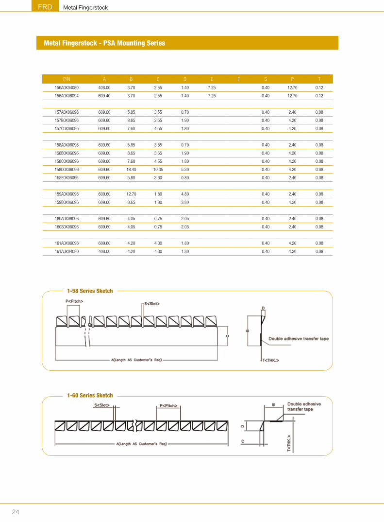
Metal Fingerstock - PSA Mounting Series
P/N A B C D E F S P T
156A0X04080 408.00 3.70 2.55 1.40 7.25 0.40 12.70 0.12
156A0X06094 609.40 3.70 2.55 1.40 7.25 0.40 12.70 0.12
157A0X06096 609.60 5.85 3.55 0.70 0.40 2.40 0.08
157B0X06096 609.60 8.65 3.55 1.90 0.40 4.20 0.08
157C0X06096 609.60 7.60 4.55 1.80 0.40 4.20 0.08
158A0X06096 609.60 5.85 3.55 0.70 0.40 2.40 0.08
158B0X06096 609.60 8.65 3.55 1.90 0.40 4.20 0.08
158C0X06096 609.60 7.60 4.55 1.80 0.40 4.20 0.08
158D0X06096 609.60 18.40 10.35 5.30 0.40 4.20 0.08
158E0X06096 609.60 5.80 3.60 0.80 0.40 2.40 0.08
159A0X06096 609.60 12.70 1.80 4.80 0.40 2.40 0.08
159B0X06096 609.60 8.65 1.80 3.80 0.40 4.20 0.08
160A0X06096 609.60 4.05 0.75 2.05 0.40 2.40 0.08
160S0X06096 609.60 4.05 0.75 2.05 0.40 2.40 0.08
161A0X06096 609.60 4.20 4.30 1.80 0.40 4.20 0.08
161A0X04080 408.00 4.20 4.30 1.80 0.40 4.20 0.08
1-58 Series Sketch
1-60 Series Sketch

25
Metal Fingerstock FRD
Metal Fingerstock - Contact Series
P/N A B P S C T L
170A0X03050 3.20 1.80 1.60 0.50 2.30 0.08 305.00
170B0X03050 3.20 2.30 1.60 0.50 2.30 0.08 305.00
170C0X03050 3.20 2.30 3.20 0.50 2.30 0.08 305.00
170D0X04060 12.20 7.10 4.80 1.65 9.40 0.15 406.00
171A0X03050 8.10 1.30 4.20 0.45 5.60 0.05 305.00
171B0X04060 22.60 3.30 4.80 1.20 16.00 0.12 406.00
171C0X04060 23.40 2.30 4.80 1.20 16.00 0.12 406.00
171D0X04060 23.40 2.30 4.75 1.20 16.00 0.12 406.00
171E0X04060 22.60 2.30 4.80 1.20 16.00 0.12 406.00
172A0X04060 4.80 2.30 1.60 0.50 3.30 0.10 406.00
172B0X04060 4.80 2.80 1.60 0.50 3.30 0.10 406.00
172C0X04060 6.90 2.80 1.90 0.65 5.60 0.15 406.00
172D0X04060 6.90 4.10 1.90 0.65 5.60 0.15 406.00
172E0X04060 11.20 4.10 2.40 0.80 8.10 0.20 406.00
172F0X4060 11.20 4.10 2.40 0.80 8.10 0.25 406.00
172G0X04060 11.20 5.10 2.40 0.80 8.10 0.20 406.00
172H0X04060 11.20 5.10 2.40 0.80 8.10 0.25 406.00
1-70 Series Sketch
1-71 Series Sketch
1-72 Series Sketch

26
Metal FingerstockFRD
Metal Fingerstock - Contact Series
P/N A B C D E F G H L P S S1 S2 T
172K1X03460 1.92 1.00 / 346.00 3.00 0.50 0.05
173A2X03430 5.25 2.00 0.70 3.10 5.00 5.40 343.00 14.82 5.00 5.40 0.05
173B2X00950 12.20 10.80 7.50 1.45 0.90 6.50 6.00 6.00 95.00 16.25 0.15
1-72K Series Sketch
1-73A Series Sketch
1-73B Series Sketch

27
Metal Fingerstock FRD
Metal Fingerstock Products
Slot Mounting Series
Clip-on Mounting Series
Track Mounting Series
PSA Mounting Series
Conductive Contact Strip and Non-standard Mount Products

28
Metal FingerstockFRD
Note


©2016 FRD0513-V3.0-Yangwww.frd.cn [email protected]
BEIJING SHANGHAI XI'AN WUHAN TAIPEI SAN JOSE (USA) SEATTLE (USA) NETHERLANDS
SHENZHEN FRD SCIENCE & TECHNOLOGY CO., LTD.FRD Building, 8# Gaofa Industrial Park, Beihuan Blvd,Nanshan District, Shenzhen, ChinaTel: 86-755-8608-1680 8608-1686Fax: 86-755-8608-1689
FRD (HONG KONG) CO., LTD.Unit 503, 5/F, Silvercord, Tower 2, 30 Canton Road,Tsimshatsui, Kowloon Hong KongTel: 852-3519-5726Fax: 852-3013-7466
KUNSHAN FRD ELECTRONIC MATERIALS CO., LTD.FRD Industrial Park, 258 Dongping Road, Bacheng, Kunshan,ChinaTel: 86-512-5785-1188Fax: 86-512-5785-1199
TIANJIN FRD SCIENCE & TECHNOLOGY CO., LTD.FRD Industrial Park, 160 Xiangyuan Road, JINGJIN Science&Tech Valley, Wuqing District, Tianjin, ChinaTel: 86-022-5969-5716Fax: 86-022-5969-5718