merging meshes using dynamic regular triangulationcomba/papers/thesis/diss-luis.pdf · merging...
TRANSCRIPT

UNIVERSIDADE FEDERAL DO RIO GRANDE DO SULINSTITUTO DE INFORMÁTICA
PROGRAMA DE PÓS-GRADUAÇÃO EM COMPUTAÇÃO
LUÍS FERNANDO MAIA SANTOS SILVA
Merging Meshes Using Dynamic Regular
Triangulation
Thesis presented in partial fulfillmentof the requirements for the degree ofMaster of Computer Science
Prof. Dr. João Luiz Dihl CombaAdvisor
Porto Alegre, March 2010

CIP – CATALOGING-IN-PUBLICATION
Silva, Luís Fernando Maia Santos
Merging Meshes Using Dynamic Regular Triangulation / LuísFernando Maia Santos Silva. – Porto Alegre: PPGC da UFRGS,2010.
53 f.: il.
Thesis (Master) – Universidade Federal do Rio Grande do Sul.Programa de Pós-Graduação em Computação, Porto Alegre, BR–RS, 2010. Advisor: João Luiz Dihl Comba.
1. Computer graphics. 2. Computational geometry. 3. Regulartriangulations. 4. Mesh merging. 5. Object modeling. I. Comba,João Luiz Dihl. II. Title.
UNIVERSIDADE FEDERAL DO RIO GRANDE DO SULReitor: Prof. Carlos Alexandre NettoVice-Reitor: Prof. Rui Vicente OppermannPró-Reitora de Pós-Graduação: Prof. Aldo Bolten LucionDiretor do Instituto de Informática: Prof. Flávio Rech WagnerCoordenadora do PPGC: Prof. Álvaro Freitas MoreiraBibliotecária-Chefe do Instituto de Informática: Beatriz Regina Bastos Haro

“Oh, so they have internet on computers now!”
— HOMER SIMPSON


ACKNOWLEDGMENTS
I have to first thank: João Luiz Dihl Comba, who give me the opportunity to jointhe UFRGS Computer Graphics Group, always watched my work closely, and helped mein all my five submissions; and Luis Gustavo Nonato for suggesting the idea of usingRegular Triangulations to perform merging of meshes, and who helped me to push mylimits while developing this work.
Thanks to my colleagues: Vitor Pamplona, Rafael Torchelsen, Denison Linus, LuizScheidegger and Tiago Etiene, with whom I had the pleasure to work; Leandro A. F.Fernandes and Francisco Pinto for interesting suggestions and discussions about mathe-matical concepts. I also thank all my lab colleagues for accepting my weird humor andstanding my annoyances every day. I would like to mention the work of professors CarlaM.D.S. Freitas, João D. Comba, Luciana P. Nedel and Manuel M. Oliveira in conduct-ing the UFRGS Computer Graphics Group to a level of excellence, and thank CNPQ forsponsoring my research during these two years.
Thanks to all friends I have made in Porto Alegre. I will always remember Mesquita,Samantha, Pablo, Gustavo, Kao, and Márcio as friends for life.
Another special thanks goes to: Paulo Barbosa for always being a loyal and patientfriend; Juan Marcus and Rafael Bezerra who also joined the challenge of masters alongwith me. To my family and all my friends, especially my parents and my brother AndréLuís for always being present in my life despite of the distance and for encouraging mealong this journey. A very special thanks goes to Soraya who accepted my decision tojoin the masters, and was by my side in every situation I have went through. It would beharder without your help.
Thanks to Prof. Paulo Sérgio (UFPI), and Prof. Luiz Cláudio da Matta (UFPI) for therecommendation letters, and Prof. Francisco Vieira (UFPI) who always believed in mycapacity and pushed me to the master level.

TABLE OF CONTENTS
LIST OF FIGURES . . . . . . . . . . . . . . . . . . . . . . . . . . . . . . . . 9
LIST OF TABLES . . . . . . . . . . . . . . . . . . . . . . . . . . . . . . . . 11
ABSTRACT . . . . . . . . . . . . . . . . . . . . . . . . . . . . . . . . . . . 13
RESUMO . . . . . . . . . . . . . . . . . . . . . . . . . . . . . . . . . . . . . 15
1 INTRODUCTION . . . . . . . . . . . . . . . . . . . . . . . . . . . . . . 171.1 Structure of this Thesis . . . . . . . . . . . . . . . . . . . . . . . . . . . 19
2 WEIGHTED DELAUNAY TRIANGULATION AND CONCEPTS . . . . 212.1 Basic Elements of a WDT . . . . . . . . . . . . . . . . . . . . . . . . . . 222.2 The Duality between PDs and RTs . . . . . . . . . . . . . . . . . . . . . 232.3 On the interpretation of the Weights . . . . . . . . . . . . . . . . . . . . 242.4 Local Convexity . . . . . . . . . . . . . . . . . . . . . . . . . . . . . . . . 252.5 Summary . . . . . . . . . . . . . . . . . . . . . . . . . . . . . . . . . . . 26
3 RELATED WORK ON REGULAR TRIANGULATIONS . . . . . . . . . 273.1 Theoretical works . . . . . . . . . . . . . . . . . . . . . . . . . . . . . . 273.2 Computational works . . . . . . . . . . . . . . . . . . . . . . . . . . . . 28
4 COMPUTING WEIGHTS . . . . . . . . . . . . . . . . . . . . . . . . . . 314.1 The Proposed Algorithm . . . . . . . . . . . . . . . . . . . . . . . . . . . 314.2 Enforcing Conformal Meshes . . . . . . . . . . . . . . . . . . . . . . . . 324.3 Summary . . . . . . . . . . . . . . . . . . . . . . . . . . . . . . . . . . . 34
5 MERGING WEIGHTED DELAUNAY TRIANGULATIONS . . . . . . . . 355.1 Convexification-based Merging . . . . . . . . . . . . . . . . . . . . . . . 365.2 Translation-based Merging . . . . . . . . . . . . . . . . . . . . . . . . . 375.3 Fringe . . . . . . . . . . . . . . . . . . . . . . . . . . . . . . . . . . . . . 385.4 Summary . . . . . . . . . . . . . . . . . . . . . . . . . . . . . . . . . . . 39
6 RESULTS AND APPLICATIONS . . . . . . . . . . . . . . . . . . . . . 416.1 Merging 2D meshes . . . . . . . . . . . . . . . . . . . . . . . . . . . . . . 416.2 Merging 3D meshes . . . . . . . . . . . . . . . . . . . . . . . . . . . . . . 436.3 Fringe . . . . . . . . . . . . . . . . . . . . . . . . . . . . . . . . . . . . . 446.4 Summary . . . . . . . . . . . . . . . . . . . . . . . . . . . . . . . . . . . 46
7 CONCLUSIONS AND FUTURE WORK . . . . . . . . . . . . . . . . . . 47

REFERENCES . . . . . . . . . . . . . . . . . . . . . . . . . . . . . . . . . . 49
LIST OF FIGURES
Figure 2.1: The Delaunay triangulation and the Voronoi diagram . . . . . . . . . 21Figure 2.2: Power Diagram, Regular Triangulation and Upper Envelope . . . . . 24Figure 2.3: The weight influence . . . . . . . . . . . . . . . . . . . . . . . . . . 24Figure 2.4: Enforcing a flipping case . . . . . . . . . . . . . . . . . . . . . . . . 25Figure 2.5: Illustrating local convexity . . . . . . . . . . . . . . . . . . . . . . . 25
Figure 3.1: Upper envelope projection . . . . . . . . . . . . . . . . . . . . . . . 28Figure 3.2: Ruppert’s Delaunay refinement . . . . . . . . . . . . . . . . . . . . . 29Figure 3.3: Examples of Slivers . . . . . . . . . . . . . . . . . . . . . . . . . . 30Figure 3.4: Safe region and a tolerance region . . . . . . . . . . . . . . . . . . . 30
Figure 4.1: Computing weights diagram . . . . . . . . . . . . . . . . . . . . . . 31Figure 4.2: Breadth first example . . . . . . . . . . . . . . . . . . . . . . . . . . 32Figure 4.3: Subdivided Edge . . . . . . . . . . . . . . . . . . . . . . . . . . . . 33
Figure 5.1: Manipulating lifted polyhedron . . . . . . . . . . . . . . . . . . . . 35Figure 5.2: Convexification-based merging . . . . . . . . . . . . . . . . . . . . . 37Figure 5.3: Translation-based merging . . . . . . . . . . . . . . . . . . . . . . . 37Figure 5.4: Convex hull issue . . . . . . . . . . . . . . . . . . . . . . . . . . . . 37Figure 5.5: Fringing process . . . . . . . . . . . . . . . . . . . . . . . . . . . . 38
Figure 6.1: 2D Cartoon Animation . . . . . . . . . . . . . . . . . . . . . . . . . 42Figure 6.2: Merging several meshes . . . . . . . . . . . . . . . . . . . . . . . . 43Figure 6.3: Aorta comparison . . . . . . . . . . . . . . . . . . . . . . . . . . . . 43Figure 6.4: Merge of Mechanical pieces . . . . . . . . . . . . . . . . . . . . . . 45Figure 6.5: Merging a buddha tetrahedral mesh . . . . . . . . . . . . . . . . . . 45Figure 6.6: Fringe comparison . . . . . . . . . . . . . . . . . . . . . . . . . . . 46


LIST OF TABLES
Table 6.1: Times for weight computation . . . . . . . . . . . . . . . . . . . . . 44Table 6.2: Times for merging . . . . . . . . . . . . . . . . . . . . . . . . . . . 44Table 6.3: Quality of tetrahedra . . . . . . . . . . . . . . . . . . . . . . . . . . 44


ABSTRACT
Simplicial meshes are used in many fields of Computer Graphics and Engineering, forinstance, in visualization, simulation, prototyping, among other applications. This kindof mesh is often used as discrete approximations of continuous spaces, where they offerflexible and efficient representations.
Considerable effort is spent in generating good quality meshes, but in some applica-tions the meshes can be modified over time. However, this kind of operation is often veryexpensive and inflexible, sometimes leading to results very different from the originalmeshes.
The ability to handle dynamic scenes reveals itself as one of the most challengingproblems in computer graphics. This work proposes an alternative technique for updatingsimplicial meshes that undergo geometric and topological changes. It explores the prop-erty that a Weighted Delaunay Triangulation (WDT) can be used to implicitly define theconnectivity of a mesh.
Instead of explicitly maintaining connectivity information, this approach simply keepsa collection of weights associated to each vertice. It consists of an algorithm to computea WDT from any given triangulation, which relies on a breadth-first traversal to assignweights to vertices, and a subdivision strategy to ensure that the reconstructed triangula-tion conforms with the original one. This technique has many applications and, in par-ticular, it allows for a very simple method of merging triangulations, which is illustratedwith both 2D and 3d examples.
Keywords: Computer graphics, computational geometry, regular triangulations, meshmerging, object modeling.


RESUMO
Combinação de Malhas utilizando Triangulações Regulares Dinâmicas
Malhas simpliciais são utilizadas em várias áreas da Computação Gráfica e Engen-haria, como por exemplo, em vizualização, simulação, prototipação, além de outras apli-cações. Este tipo de malha é, geralmente, utilizada como aproximações discretas de es-paços contínuos, onde eles oferecem representações flexíveis e eficientes.
Muito esforço é gasto visando gerar malhas de boa qualidade, porém, em alguns casosas malhas acabam sendo modificadas. Entretanto, este tipo de operação é geralmentecustosa e inflexível, o que pode resultar na geraão de malhas bem diferentes das originais.
A habilidade de manipular cenas dinâmicas revela-se um dos problemas mais desafi-adores da computação gráfica. Este trabalho propõe um método alternativo para atualizarmalhas simpliciais que vai além de mudanças geométricas e topológicas. Tal métodoexplora uma das propriedade das Tringulações de Delaunay com Pesos, que permite ausá-las para definir implicitamente as relações de conectividade de uma malha.
Ao contrário de manter as informações de conectividade explicitamente, a atual abor-dagem simplesmente armazena uma coleção de pesos associados a cada vértice. Alémdisso, criamos um algoritmo para calcular uma Tringulação de Delaunay com Pesos a par-tir de uma dada triangulação. O algoritmo consiste em uma busca em largura que atribuipesos aos vértices, e uma estratégia de de subdivisão para assegurar que a triangulaçãoreconstruída será correspondente à original. Este método apresenta diversas aplicaçõese, em particular, permite a criação de um sistema simples de realizar combinação entretriangulações, que será ilustrada com exemplos em 2D e 3D.
Palavras-chave: computação gráfica, geometria computacional, triangulações regulares,combinação de malhas, modelagem.

17
1 INTRODUCTION
Simplicial meshes, also known as triangulations, are used in computer graphics, geo-metric computing, engineering, visualization, simulations, among other areas. They arepreferred due to their ability to represent irregular and adaptive domains.
There are many works dedicated to optimize mesh quality, and generate good meshtriangulations (LUEBKE et al., 2002; GARLAND; HECKBERT, 1997; COHEN et al.,1996; TOURNOIS et al., 2009). Furthermore, several rendering aspects depend upongood quality meshes. For instance, texture mapping is degraded by topological changes,demanding continuous texture coordinates updates to ensure a correct mapping. Sincemuch effort is spent in improving mesh triangulations, it is expected of applications tomaintain such properties. In fact, when dealing with static scenes, these properties arekept. However, some applications demand the use of dynamic scenes, which can im-ply the loss of the original mesh quality. For instance, dynamic data structures for vis-ibility ordering often require partial or total reconstruction of data structures (TORRES,1990; CHRYSANTHOU; SLATER, 1992; NAYLOR, 1992; LUQUE; COMBA; FRE-ITAS, 2005), and the capacity to handle these scenes reveals to be one of the most chal-lenging problems in computer graphics.
A common problem that arises when handling dynamic scenes is that the result of amesh processing operation can either require a costly mesh re-computation, thus impair-ing real-time usage, or it demands constant updates and additional storage to keep severalinformation needed to perform this task. In particular, the connectivity information ishard to update, and it is often destroyed or modified during such operations. Often meshoperations such as merging, morphing, and simplification (among others) alter the num-ber of vertices in the mesh (either by adding or deleting vertices), which requires that theconnectivity must be changed accordingly.
While updating a mesh triangulation, it is necessary to attempt to maintain both con-sistence and correctness of adjacency and incidence relations between simplicial ele-ments. There are works that focus on checking and repairing triangulations using datastructures (e.g., kinetic data structures (GUIBAS, 2004)). Recently, these challenges havebeen driving forward development of point-based (hybrid) approaches (GROSS; PFIS-TER, 2007).
An alternative solution to this problem involves focusing only on triangulations whoseconnectivity can be implicitly derived from geometric constraints (TOURNOIS et al.,2009; CHENG et al., 1999; TOURNOIS; SRINIVASAN; ALLIEZ, 2009), such as De-launay Triangulations (DT) (EDELSBRUNNER; SEIDEL, 1986). However, these ap-proaches are rather limited, since in many cases the underlying meshes might not complywith the required geometric constraints, returning to the case where it is needed to managemesh connectivity explicitly (CASTRO et al., 2009).

18
Another point to be considered is that the interplay of mesh operations might lead todifferent connectivity information depending on the order that operations are performed.Consider the situation where a set of vertices is removed from a mesh and later rein-serted. The recovery of the exact original mesh is expected, since, as mentioned before,improving meshes triangulation demands great effort. While it is easy to enforce for thegeometric coordinates of the vertices, preserving the connectivity is hard, and only a veryrestrictive class of surface meshes can be algorithmically reconstructed from the geometryof its vertices (i.e. disregarding connectivity information).
This work proposes an alternative technique for updating simplicial meshes that un-dergo geometric and topological changes and explores the property that a Weighted De-launay Triangulation (WDT) can be used to implicitly define the connectivity of a mesh.The method naturally supports applications that require dynamic meshes, without theneed for explicit connectivity management. A key contribution of this work is the exten-sion of Delaunay-based implicit connectivity representations to general triangulations.
The presented proposal is based on a generalization of Delaunay triangulations calledWeighted Delaunay triangulations (WDT), also known as Regular Triangulation (RT).WDTs are a generalization of DTs where a weight is associated with each vertice in themesh. The weights can be modified in such a way to change the connectivity of the mesh,therefore providing to WDTs the ability to represent a wider collection of meshes. Still,not every triangulation can be represented as a WDT. A important feature of this work isto use a subdivision scheme to turn any mesh into a WDT through the addition of extravertices (see Section 4.2).
This approach allows mesh operations to be performed by simple manipulating verticeweights. For instance, to remove a vertice requires only to set the weight to an appropri-ate value, which causes its automatic elimination from the hull, and therefore from thetriangulation (EDELSBRUNNER; SEIDEL, 1986).
A previous work by Cignoni and De Floriani (Cignoni; De Floriani, 1998) proposeda technique for computing a WDT from a given mesh by modeling the weight constraintsas a linear program. Balaven et al. (BALAVEN et al., 2002) also modeled a linearprogramming technique to solve a problem of transitional meshes. Unfortunately, thissolution cannot be generalized, and the linear program might not have a solution in somecases. The proposed approach is based on a breadth-first traversal of the mesh that locallyenforces convexity constraints on the lifting construction, together with a subdivisionmechanism, which ensures that the resulting WDT conforms with the original mesh (seeChapter 4 for details).
The presented method offers a general way to deal with the lifting construction, allow-ing the definition of different merging techniques. These techniques can be constructedto produce results customized to particular applications. This work presents and discusstwo ways to merge WDTs based on different ways of combining the lifted polyhedronof each mesh (see Chapter 5). It is also proposed a new adaptive scheme that maintainsthe geometric quality of simplices when merging meshes of distinct refinement levels(see Section 5.3). This approach generates an adaptive triangulation that varies smoothlybetween the meshes that will be merged.
The technique described in this dissertation was implemented and a number of ex-periments were performed to its validation. In particular, applications that demonstratethe merging of 2D and 3D meshes are presented at Chapter 6. Despite their simplicity,the proposed merging approaches automatically ensure that the connectivity between themeshes being merged remains consistent and well defined at all times, without the need

19
for complex data-structures.In summary, the following contributions are introduced in this work:
• A new approach for computing a WDT from an arbitrary simplicial mesh;
• Two algorithms for merging regular triangulations;
• A simple fringe mechanism that establishes a smooth transition between mergedmeshes with different refinement levels;
• Validation of the proposed technique with examples in 2D and 3D
The weight computation and merging schemes are all based on very simple geometricconstructions which do not demand complex data-structures. Besides, the method canautomatically merge multiple triangulations with distinct mesh resolutions and arbitrarytopology, while still ensuring consistent and well-defined connectivity. Those propertiespoint out the method as simple and general. But it is also preservable, since mesh featurestend to be preserved during the merging process, specifically the mesh anisotropy.
1.1 Structure of this Thesis
The remaining of this thesis is organized as follows: Chapter 2 introduces the WDTsand basic concepts that are fundamental to the understanding of this work. Chapter 3reviews related work in comparison to the proposed approach. Chapter 4 describes theproposed technique to store the mesh triangulation on the vertices weights together with asubdivision mechanism, which ensures that the resulting WDT conforms with the originalmesh. Chapter 5 presents the two merging methods developed using DRT. Chapter 6 illus-trates the potential of the proposal in some applications. Chapter 7 summarizes relevantproperties of this work and lists some avenues for future exploration.

20

21
2 WEIGHTED DELAUNAY TRIANGULATION AND CON-CEPTS
There is a set of mathematical concepts and properties that should be explained be-fore diving into the proposed approach. The purpose of this chapter is, therefore, toaddress these concepts, since they are essential to the understanding of how WDTs can beemployed towards representing any triangulation, and how the merging techniques weredeveloped.
The Delaunay triangulation was created by Boris Delaunay in 1934 (DELAUNAY,1934), and is built from the dual graph of the Voronoi Diagram (BERG et al., 2000;AURENHAMMER, 1991) as shown in Figure 2.1. A inherent property of Delaunaytriangulations is to maximize the minimum angle of all the angles of the triangles in thetriangulation, thus tending to avoid sliver triangles.
(a) (b)
Figure 2.1: Relation between the dual graph of the Voronoi tessellation and the Delau-nay Triangulation. a) A Voronoi diagram and its corresponding graph; b) A Delaunaytriangulation and the Voronoi diagram of a set of points.
As mentioned before, a Weighted Delaunay Triangulations (WDT), also called Reg-ular Triangulation (RT), is a generalization of the Delaunay triangulation, where eachvertice has an associated weight. A key property of DTs is the fact that all their verticescan be lifted onto a convex polyhedron in one extra dimension (also known as the liftingproperty (EDELSBRUNNER; SEIDEL, 1986; AURENHAMMER, 1987)). However,the same is not true for non-Delaunay meshes. On a WDT, the weight modifies the heightof the lifted vertices, thus moving them in or out of the lifted polyhedron. Later in thischapter we show how we use this property to save a mesh connectivity.
22
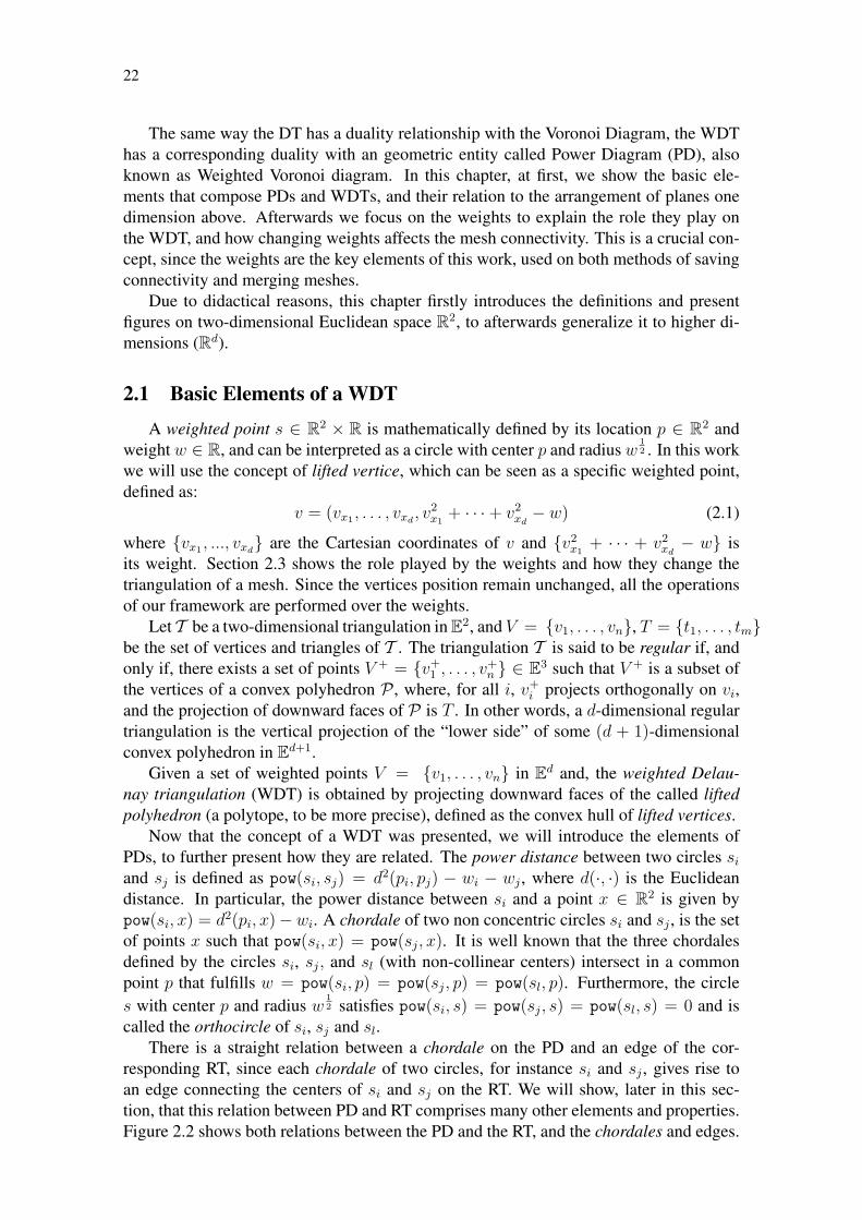
The same way the DT has a duality relationship with the Voronoi Diagram, the WDThas a corresponding duality with an geometric entity called Power Diagram (PD), alsoknown as Weighted Voronoi diagram. In this chapter, at first, we show the basic ele-ments that compose PDs and WDTs, and their relation to the arrangement of planes onedimension above. Afterwards we focus on the weights to explain the role they play onthe WDT, and how changing weights affects the mesh connectivity. This is a crucial con-cept, since the weights are the key elements of this work, used on both methods of savingconnectivity and merging meshes.
Due to didactical reasons, this chapter firstly introduces the definitions and presentfigures on two-dimensional Euclidean space R2, to afterwards generalize it to higher di-mensions (Rd).
2.1 Basic Elements of a WDT
A weighted point s ∈ R2 × R is mathematically defined by its location p ∈ R2 andweight w ∈ R, and can be interpreted as a circle with center p and radius w
12 . In this work
we will use the concept of lifted vertice, which can be seen as a specific weighted point,defined as:
v = (vx1 , . . . , vxd, v
2x1
+ · · · + v2xd− w) (2.1)
where {vx1 , ..., vxd} are the Cartesian coordinates of v and {v2
x1+ · · · + v2
xd− w} is
its weight. Section 2.3 shows the role played by the weights and how they change thetriangulation of a mesh. Since the vertices position remain unchanged, all the operationsof our framework are performed over the weights.
Let T be a two-dimensional triangulation in E2, and V = {v1, . . . , vn}, T = {t1, . . . , tm}be the set of vertices and triangles of T . The triangulation T is said to be regular if, andonly if, there exists a set of points V + = {v+
1 , . . . , v+n } ∈ E3 such that V + is a subset of
the vertices of a convex polyhedron P , where, for all i, v+i projects orthogonally on vi,
and the projection of downward faces of P is T . In other words, a d-dimensional regulartriangulation is the vertical projection of the “lower side” of some (d + 1)-dimensionalconvex polyhedron in Ed+1.
Given a set of weighted points V = {v1, . . . , vn} in Ed and, the weighted Delau-nay triangulation (WDT) is obtained by projecting downward faces of the called liftedpolyhedron (a polytope, to be more precise), defined as the convex hull of lifted vertices.
Now that the concept of a WDT was presented, we will introduce the elements ofPDs, to further present how they are related. The power distance between two circles si
and sj is defined as pow(si, sj) = d2(pi, pj) − wi − wj , where d(·, ·) is the Euclideandistance. In particular, the power distance between si and a point x ∈ R2 is given bypow(si, x) = d2(pi, x)−wi. A chordale of two non concentric circles si and sj , is the setof points x such that pow(si, x) = pow(sj, x). It is well known that the three chordalesdefined by the circles si, sj, and sl (with non-collinear centers) intersect in a commonpoint p that fulfills w = pow(si, p) = pow(sj, p) = pow(sl, p). Furthermore, the circles with center p and radius w
12 satisfies pow(si, s) = pow(sj, s) = pow(sl, s) = 0 and is
called the orthocircle of si, sj and sl.There is a straight relation between a chordale on the PD and an edge of the cor-
responding RT, since each chordale of two circles, for instance si and sj , gives rise toan edge connecting the centers of si and sj on the RT. We will show, later in this sec-tion, that this relation between PD and RT comprises many other elements and properties.Figure 2.2 shows both relations between the PD and the RT, and the chordales and edges.

23
Let hsi(sj) denote the closed half-space bounded by the chordale of si and sj thatcontains the points with the smallest power distance to si. The power cell of si is givenby
V (si) =�
j, j �=i
hsi(sj) (2.2)
Letting S = {s1, . . . , sn} be a set of non-concentric circles, the power cells of the cir-cles in S comprise a partition of R2 in convex polygons, called Power Diagram (PD(S)).The Power Diagram coincides with the usual Voronoi Diagram if all circles in S have thesame radius. In other words, in the same way the WDT is a generalization of the DT, thePower Diagram is an extension of the Voronoi Diagram.
However, the Power Diagram produced by circles with different radius may not satisfythe containment condition, that is, a circle si may not be contained in its power cell.Furthermore, depending on the weights, a circle can give rise to an empty power cell. Inthis case, such circle is called redundant. According to this property, in order to excludea vertice from the PD, and therefore from the RT, it is only necessary to reduce its weightso that it gives rise to an empty cell. Under the same premise, a vertice can be insertedinto both RT and PD by simply giving it a big enough weight to create a non empty powercell.
If we assume that the center of the circles in S are not collinear, then the intersectionof three (or more) power cells is either empty or a vertice of PD(S). It is not difficultto realize that a vertice of PD(S) is the center of the orthocircle defined by at least threecircles whose power cells have non-empty intersection. In a non-degenerate case, eachvertice v of PD(S) is defined by the intersection of exactly three power cells. In suchcase, the center of the three circles whose power cells intersect in v define a triangle andthe union of all triangles makes up a simplicial complex, called Regular Triangulation.
In fact, such a correspondence leads to a duality relationship that associates circles topower cells, power cell edges to triangle edges and Power Diagram vertices to triangles. Inthis last case the Power Diagram vertice is called the orthocircle of the associated triangle.Note that redundant circles do not have dual power cells, and thus do not appear at the RT.From the duality property we can obtain the RT from the Power Diagram (and vice versa)in O(n). In the two-dimensional case there are algorithms that compute both structures inO(n log n) (EDELSBRUNNER; SHAH, 1996) (expected time). In Chapter 4 we presentways to use the duality relation mentioned above in order to set weights to the vertices insuch a way their corresponding planes maintain a given triangulation.
The concepts above mentined have corresponding elements on the three-dimensionalEuclidean space R3. A weighted point can be seen as a sphere with center p and radiusw
12 , while the chordales of a PD being a shared face between two adjacent points. In R3
the orthocircle is defined by four distinct weighted points and the power cell is a three-dimensional volume surrounding the point.
2.2 The Duality between PDs and RTs
An important fact that is deeply explored in this work is the strong relation betweenPower Diagrams in R2 and arrangement of planes in R3 (consequently, for a Power Di-agram in R3 the arrangement of planes are in R4). Such a relationship can be obtainedby associating each circle si ∈ S with a non vertical plane in R3, which is defined by thefollowing function:
πsi(x) = 2 < x, pi > − < pi, pi > +wi (2.3)
24
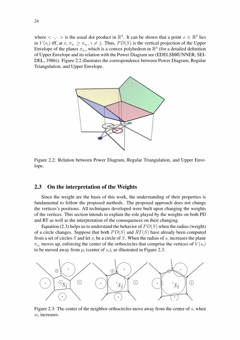
where < ·, · > is the usual dot product in R2. It can be shown that a point x ∈ R2 liesin V (si) iff, at x, πsi ≥ πsj , i �= j. Thus, PD(S) is the vertical projection of the UpperEnvelope of the planes πsi , which is a convex polyhedron in R3 (for a detailed definitionof Upper Envelope and its relation with the Power Diagram see (EDELSBRUNNER; SEI-DEL, 1986)). Figure 2.2 illustrates the correspondence between Power Diagram, RegularTriangulation, and Upper Envelope.
Figure 2.2: Relation between Power Diagram, Regular Triangulation, and Upper Enve-lope.
2.3 On the interpretation of the Weights
Since the weight are the basis of this work, the understanding of their properties isfundamental to follow the proposed methods. The proposed approach does not changethe vertices’s positions. All techniques developed were built upon changing the weightsof the vertices. This section intends to explain the role played by the weights on both PDand RT as well as the interpretation of the consequences on their changing.
Equation (2.3) helps us to understand the behavior of PD(S) when the radius (weight)of a circle changes. Suppose that both PD(S) and RT (S) have already been computedfrom a set of circles S and let si be a circle of S. When the radius of si increases the planeπsi moves up, enforcing the center of the orthocircles that comprise the vertices of V (si)to be moved away from pi (center of si), as illustrated in Figure 2.3.
Figure 2.3: The center of the neighbor orthocircles move away from the center of si whenwi increases.

25
Due to the duality relationship, the RT remains unchanged until the increase of wi
gives rise to a degenerate case, that is, two diagram vertices are collapsed into a singleone, causing the intersection of more than three power cells in such vertice. When adegenerate case occurs, any further increase of wi gives rise to an edge flipping in theRT, as shown in Figure 2.4. Meanwhile the same process occurs to the planes defined bythe circles onto the corresponding arrangement of planes. A similar phenomenon occurswhen the weight wi is reduced.
(a) (b) (c)
Figure 2.4: Edge flipping after a degenerate case. a) original configuration; b) the increasein the weight of si gives rise to a degenerate case; c) further increase of wi causing an edgeflip.
The dynamic process described above allows us to control the weights so as to avoidedges flipping. Furthermore, the understanding of such a dynamics is the main key toconvert any given triangulation into a WDT, as we shall see in Chapter 4.
2.4 Local Convexity
In this section we present the concept of local convexity, which is further(in Chap-ter 4) used to assign weights to the vertices of a mesh in order to encode its originaltriangulation. Again, for didactical purposes, we show the concepts in R2.
Let ti and tj be two adjacent triangles sharing a common edge rij (in E3 rij will be atriangle shared by two adjacet tetrahedra) and t
+i , t
+j be the lifted simplices of ti and tj .
The edge r+ij is said to be locally convex if the (d + 1)-simplex generated from the union
of vertices in t+i and t
+j lies on the upper half-space of each hyperplane containing t
+i and
t+j (Figure 2.5 shows the lifting process in R2). A polyhedron in Ed+1 is called locally
convex if all edges shared by two triangles are locally convex.
Figure 2.5: Simplices are lifted to ensure local convexity.
Local convexity is a necessary, but not sufficient, condition to ensure global convexityof a polyhedron (MEHLHORN et al., 1996). However, in the particular case of a polyhe-dron generated by lifting a convex triangulation, local convexity leads to global convexity

26
(see (DEVILLERS et al., 1998) for details) and, as remarked by Balaven et al. (BAL-AVEN et al., 2002), this property has widely been used as a mechanism to verify whethera given triangulation is regular. As we show in the next section, the association betweenlifting and local convexity comprises the core of our approach.
It is important to highlight that not every triangulation is regular. See, for example,the classic seven triangle mesh shown in (EDELSBRUNNER; SHAH, 1996). Becauseof this, it may be impossible to build a convex polyhedron whose projection matches agiven triangulation, and therefore any lifting of this triangulation will contain at least onenon-locally convex (d− 1)-simplex.
2.5 Summary
This chapter presented a brief overview of the elements that compose a WDT as wellas its duality relation with the arrangement of planes. Such description was intended toprovide just enough information to familiarize the reader with some concepts that will beused in the next chapters. An in-depth description of these subjects is beyond the scopeof this thesis and can be found in the works mentioned on Chapter 3.
27
3 RELATED WORK ON REGULAR TRIANGULATIONS
This chapter summarizes the most important academic efforts concerning DelaunayTriangulations and connectivity oblivious methodologies in computer graphics. Since theproposed technique is validated using dynamic meshes, it also reviews the main issuesregarding connectivity reconstruction in this context.
Regular Triangulations and Power Diagrams (EDELSBRUNNER; SEIDEL, 1986;AURENHAMMER, 1987) are basic geometrical tools that have been often used for prob-lems related with surface (AMENTA; CHOI; KOLLURI, 2001), quality mesh genera-tion for numerical simulations (CHENG; DEY; RAMOS, 2007; CHENG; DEY; RAY,2005; CUADROS-VARGAS et al., 2005), and depth sorting (EDELSBRUNNER, 1989;Cignoni; De Floriani, 1998). The essential task of assigning weights to points makes RTand Power Diagram an extremely flexible and dynamic geometrical structure, and its use-fulness goes beyond mesh generation. Several theoretical and computational frameworkshave been developed towards understanding and exploring such potentiality.
In regard to connectivity oblivious techniques, their use for manipulation of simpli-cial meshes can be divided into two main categories: methods that reproduce an existingtriangulation from geometric information, and methods that build a triangulation basedon the constraints given by curves and/or surfaces defined in the domain of interest. Inboth cases, the vast majority of approaches relies on the properties of DTs and WDTsto avoid explicitly handling the mesh connectivity. These methods have solid founda-tions on both theoretical (AURENHAMMER, 1987; AURENHAMMER; IMAI, 1987;EDELSBRUNNER; SEIDEL, 1986) and computational (VIGO; PLA; COTRINA, 2002;EDELSBRUNNER; SHAH, 1996; EDELSBRUNNER, 2001) sides.
3.1 Theoretical works
Theoretical techniques construct a WDT corresponding to a given mesh by comput-ing a valid set of weights for its vertices. The advantage of this approach is that, oncethe weights are computed, connectivity information can be discarded. The original trian-gulation can then be rebuilt algorithmically from vertice coordinates and weights. Thistechnique presents great advantages over connectivity dependent approaches, since manymesh processing operations have to create versions of input meshes with different con-nectivity information. For instance, morphing between meshes requires generating an in-termediate mesh that combines the geometric and topological aspects of the input meshes.
Common to all methods discussed in the literature is the definition of a correspondencebetween vertices and connectivity information. This is often done by first creating amapping into an unified space for the geometry and connectivity of both meshes, and bya synthesis algorithm that generates an intermediate mesh from this space.
28
Several papers discuss aspects that range from how and when such mappings are de-fined (FLOATER; C.GOTSMAN, 1999; SURAZHSKY; GOTSMAN, 2001; DANCIGER;DEVADOSS; SHEEHY, 2006), to how mesh information can be mapped to a parametricspace, such as the inter-surface mapping described in (SCHREINER et al., 2004). Thereare several variations on how the connectivity information is generated for intermediatemeshes (AHN; LEE, 2002; AHN; LEE; SEIDEL, 2004; PARUS; KOLINGEROVá, 2004;LEE et al., 1999; ZORIN; SCHRöDER; SWELDENS, 1996; BREEN et al., 2001). Thiswork offers an implicit way to reconstruct connectivity information that can be used inconjunction with several of the methods proposed.
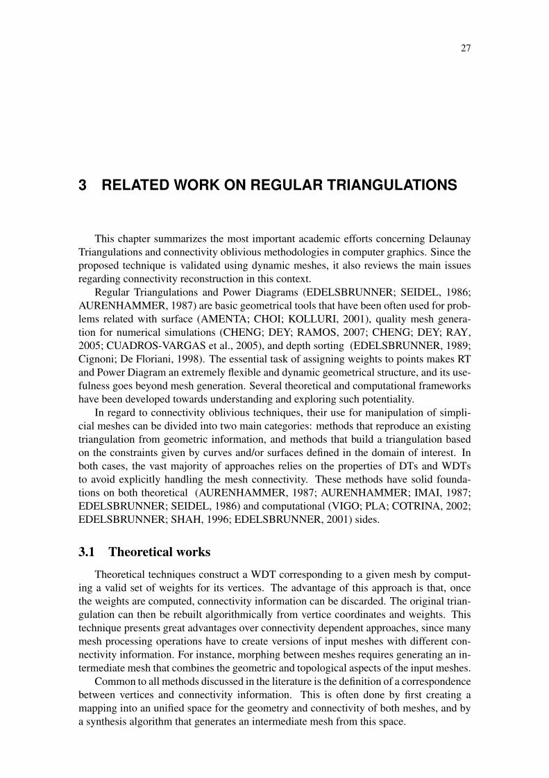
A well explored way for computing a valid set of weights is to reduce the problem toa linear programming problem, looking for an optimal weight distribution. Edelsbrunner(EDELSBRUNNER, 1999; PIRES, 2008) explored the equivalence between RTs (PowerDiagrams) and the boundary of convex polyhedra in one dimension above (also calledthe lifting property (EDELSBRUNNER; SEIDEL, 1986; AURENHAMMER, 1987)) asshown in Figure 3.1. From this relations, Edelsbrunner derived an algebra of spheres toformulate a new paradigm for designing smooth surfaces.
The relationship between RT and convex polyhedra has also been investigated byMassada et al (MASADA; IMAI; IMAI, 1996), who proposed an output-size sensitivealgorithm to enumerate all RTs. From a theoretical point of view, it has been shown aclose connection to well established algebraic concepts, such as the relation of RTs andconvex polyhedra to Gröbner bases (DELOERA; STURMFELS; THOMAS, 1995).
Figure 3.1: Relation between vertices and its projections onto the upper envelope as pre-sented in (BALAVEN et al., 2002).
Cignoni and De Floriani (Cignoni; De Floriani, 1998) use this formulation to performdepth sorting of unstructured simplicial meshes, without having to store connectivity in-formation. They explore the lifting property of RTs to compute a convex polyhedron in a(d + 1)-dimensional space whose projection on the d-dimensional space is the simplicialcomplex one wished to depth sorting.
Balaven et al. (BALAVEN et al., 2002) modelated a linear problem using RTs togenerate transitional meshes for oil reservoir simulations. However, their solution has thelimitation of only dealing with meshes that can be represented as WDTs. When this is notthe case, they have to fall back to explicit management of connectivity information. As far

29
as we know, no satisfactory alternative has been proposed to overcome these limitations,and the presented approach addresses the problem of weight computation in a differentway, avoiding the linear programming formulation altogether.
3.2 Computational works
Computational techniques are much more numerous, and in general these methodsare concerned with either object modeling or domain decomposition for numerical sim-ulation. While for object modeling, the focus is on generating a triangulation that ap-proximates a given model, using geometric certificates to filter undesirable simplices, fordomain decomposition methods, the focus is on ensuring that output meshes comply withconstraints given by curves and/or surfaces defined inside the domain of interest. Despitetheir different focus, both branch of approaches aim at enforcing the quality for simplicialelements.
Amenta et al. (AMENTA; CHOI; KOLLURI, 2001) created a Delaunay-based surfacereconstruction from point clouds. They first approximate the medial axis transformationof the object, and from it they apply an inverse transformation to produce the surface.Their approach is based on (AMENTA; BERN, 1998; AMENTA; BERN; KAMVYS-SELIS, 1998) and uses the vertices farthest of its Voronoi cell of a surface, which weredefined as poles, to be selected as an approximation of the medial axis.
Delaunay triangulations were also used on isosurfacing methods, for instance Chenget al. (CHENG et al., 2004) maintained the restricted Delaunay of a set of points sampledon the surface by using a height function on the surface to generate more sample pointsdictated by certain conditions while updating the triangulation. Boissonnat and Oudot(BOISSONNAT; OUDOT, 2005) introduced the concept of Lipschitz radius which wasused to determine a sampling condition to be used on surface reconstruction.
(a) (b) (c)
Figure 3.2: Delaunay refinement comparison (RUPPERT, 1993). a) Sample input planarstraightline graph (PSLG); b) typical (non-Steiner) triangulation of PSLG and boundingbox; c) Delaunay refinement algorithm’s output.
Many studies were conducted on mesh refinement making use of Delaunay Triangu-lations. For example, Chew (CHEW, 1987) proposed an O(n log n) time algorithm toconstruct a constrained Delaunay Triangulation using a divide-and-conqueror approach.Thereafter, Ruppert (RUPPERT, 1993) created a technique based upon Chew’s workwhich consisted in a successive refinement algorithm (see Figure 3.2). Later on, Shewchuk(SHEWCHUK, 2002) improved both Chew’s and Ruppert’s techniques and helped to

30
solve a weakness their approaches presented when handling meshing of non-manifolddomains with small angles.
(a) (b) (c) (d)
Figure 3.3: Examples of poor quality tetrahedra (LABELLE, 2006) eliminated by SliverExudation.
Another mesh refinement technique using Delaunay Triangulations is the work ofCheng et al. (CHENG et al., 1999) named Sliver Exudation. Slivers can be defined astetrahedra whose four vertices lie close to a plane and whose projection to that planeis a convex quadrilateral with no edge (CHENG et al., 1999). In his work, Cheng ex-plored Weighted Delaunay Triangulations properties and proposed an algorithm to com-pute weights for vertices of a triangulation in such a way to eliminate slivers (see Fig-ure 3.3). Furthermore Edelsbrunner and Guoy (EDELSBRUNNER; GUOY, 2001) con-ducted an experimental study of sliver exudation to prove its effectiveness. Section 5.3 ofthis work introduces the fringe, which is an approach used to adapt meshes of differentgranularity during the merging process. It also has the advantage of avoiding the insertionof slivers when reconstructing the triangulation.
Figure 3.4: The region A is the safe region of the point placed on the center of B, while Bis its tolerance region (CASTRO et al., 2009).
Castro et al. (CASTRO et al., 2009) explored the problem of updating Delaunay Trian-gulations when its vertices move. They developed a set of filters based upon the conceptof vertice tolerance to determine whether it is better to update the whole triangulationfrom scratch or only reallocate the vertices. From these filters, Castro was able to deter-mine a safe region and a tolerance region within a vertice could move without the need ofupdating the triangulation. Figure 3.4 illustrates the concepts of safe region and toleranceregion.

31
The majority of the works referred before are examples of connectivity oblivious ob-ject modeling. Within this context, the proposed methodology can be seen as an alterna-tive mechanism to encode connectivity information on vertices weights and a WDT basedmerging approach. The proposed merging technique proves that many object modelingmethods can be implemented by extending this framework.

32

33
4 COMPUTING WEIGHTS
In the previous chapter we presented the main concepts upon which RT and PD stand,as well as the notion of local convexity and the importance of weights on changing thestructure of the triangulation on a WDT. This chapter introduces the approach we devel-oped to create a conformal mesh from a original triangulation by computing and assigningweights to vertices. We also present a method to handle special cases when the weightassignment procedure does not ensure a complete match between the original and theconformal mesh.
We start from a given triangulation T in Ed, and our goal is to compute a set of weightsfor its vertices to represent T as a weighted Delaunay Triangulation (see Figure 4.1). Werely on a geometric construction in Ed+1 that explores the lifting and local convexityproperties previously mentioned in Section 2.4 to compute the weights. A triangulationconforming to the original mesh can be reconstructed by an algorithm that computes aweighted Delaunay triangulation from vertice coordinates and associated weights (see,for example, (EDELSBRUNNER; SHAH, 1996)). Hence, incidence and adjacency re-lations between simplices can be recovered from weighted vertices, and therefore we candisregard the mesh connectivity.
Original!Triangulation!
Weighted!Vertices!
Conformal!Weighted!
Mesh!
Weighted Delaunay Triangulation!
Lifting! Subdivision!
Figure 4.1: WDT computation: the original triangulation is traversed in a breadth-firstmanner to assign weights to vertices using the lifting construction. A following subdivi-sion step ensures that the resulting weighted mesh conforms with the original triangula-tion.
4.1 The Proposed Algorithm
The proposed algorithm starts by an elected d-simplex (a triangle in R2 or a tetrahe-dron in R3) which is called seed. If no seed is specified we chose the d-simplex closest tothe centroid, thus the lifted polyhedron is prone to be balanced.
For a better understanding of the method we will start to explain the algorithm usingthe two-dimensional case and further move to higher dimensional cases. Take ti and tj
as triangles of a triangulation T sharing a common edge rij . Suppose that weights havealready been assigned to vertices of ti, thus it becomes t
+i . We can compute the hyperplane

34
πi containing t+i , that is, πi is the support hyperplane of t
+i . Let v be the vertice of tj
opposite to rij and v be the vertical projection of v onto πi, as illustrated in Figure 2.5.Notice that a small vertical perturbation of v toward the positive half-space of πi, denotedas v+, makes r
+ij locally convex with respect to t
+i , and t
+j = r
+ij ∪ v+. Therefore, moving
to the generic case (in Ed) the coordinates of v are (vx1 , . . . , vxd, vxd+1
), and we can useequation ( 2.1) to define the weight wv of the vertice v as:
wv = v2x1
+ . . . + v2xd− (vxd+1
+ �) (4.1)
where � is a small vertical perturbation of v that makes r+ij locally convex with regard to
t+i and t
+j .
The same formulation was used for the three-dimensional case where two adjacenttetrahedra share a common face and the computed hyperplane πi is in E4. In the Chapter 6of this work we show results of the proposed technique along with the merging approachpresented in Chapter 5 illustrated with examples in 2D and 3D.
Figure 4.2: Simplices are lifted using a breadth first scheme, red simplices are liftedensuring local convexity, but local convexity can not be ensured for edges of the yellowtriangle.
By repeating the construction above for all neighbor simplices of each lifted d-simplex(red triangles in Figure 4.2), we can ensure that each lifted (d−1)-simplex is locally con-vex. Although weights are assigned consistently to vertices of T , some (d− 1)-simplices(an edge in R2 or a face in R3) of the original triangulation are not handled during theweight computation process described above (see the yellow triangle in Figure 4.2). How-ever, most of these cases are locally convex naturally and do appear in the reconstructedtriangulation.
In Section 4.2 we describe how to handle the simplices that do not automatically fitthis criteria by employing a subdivision process to handle these simplices, thus ensuringthat a convex polyhedron is generated as output. As a result, the original triangulationcan be rebuilt from the weighted vertices, even though a few simplices of T may appearsubdivided after the reconstruction.
4.2 Enforcing Conformal Meshes
Absent simplices can be forced to appear in the weighted triangulation by using asubdivision process, which is usually employed in many Delaunay-based mesh generationand modeling techniques (NONATO et al., 2005). These subdivision strategies ensure thatthe reconstructed weighted triangulation conforms with the original triangulation. We willpresent the formulation used to fix this issue on the n-dimensional case, to further exhibita two-dimensional example of the method.

35
Formally, given a triangulation T in Ed, the subdivision process ensures that for eachk-simplex r of T there exists a set of k-simplices rw1 , . . . , rws , s ≥ 1 in Tw (the re-constructed weighted triangulation) such that |r| = |rw1 ∪ · · · ∪ rws |, where |r| is theunderlying space of r.
Figure 4.3: A red edge is absent from the final triangulation (first). Absent edges areincluded by a recursive subdivision process that generate new vertices with proper weightassignments (second and third).
Suppose that an edge e ∈ T is absent from Tw, where Tw is the weighted triangulationobtained as described before. The subdivision step consists of splitting e at its midpointve, and assigning a weight to ve to ensure that it appears in the weighted triangulation. Asillustrated on the left of Figure 4.3, the absent edge e intersects a set Twe of d-simplicesin Tw. To keep changes as local as possible, we ensure that the weight of ve only altersthe simplices of Twe , and maintains the remaining triangulation unchanged. This propertycan be satisfied by computing the weight of ve as follows: let tve be the d-simplex of Tw
containing ve and t+vebe the lifting of tve in Ed+1. We call lve the vertical line through
ve, and compute the intersection point ve1 between lve and the support hyperplane of t+ve,
as well as the highest intersection ve2 of lve with the hyperplanes supporting the liftedd-simplices in Tw − Twe .
It is easy to see that any choice of weight assignment that places v+e strictly between
ve1 and ve2 ensures that ve will appear in the weighted triangulation (v+e will be under-
neath the lifted convex hull). This approach only modifies the simplices in Twe , sincev+
e is above the hyperplanes supporting the simplices in Tw − Twe . In our current imple-mentation, we set a weight that places v+
e halfway between ve1 and ve2 . Although thisprocedure adds ve to the weighted triangulation, it does not ensure that each sub-segmentof e will appear in the triangulation. If a sub-segment still does not appear, we recursivelyapply the same procedure. Since the lifting of each new vertice is placed below existingsimplices, the subdivision process finishes in a finite number of steps. In practice, veryfew absent simplices demand more than one or two iterations.
The procedure described above for recovering absent edges can be extended to en-force triangular faces in three-dimensional triangulations. The centroid of each missingtriangular face is inserted and positioned exactly as was done for absent edges. In fact,in the three-dimensional case, we first recover all missing edges before splitting absentfaces, since most missing triangles naturally appear after the edges are recovered.
36
4.3 Summary
Conventional approaches to weight computation try to solve a linear programmingproblem (BALAVEN et al., 2002), which may not have a solution. On the other hand, weuse a deterministic procedure that builds an approximation of a locally convex polyhedronin Ed+1. However, this step generates a preliminary weight assignment that might notenforce local convexity to some (d − 1)-simplices. The proposed subdivision methodsolves this issue.
A major advantage of using WDT to process meshes is that it automatically ensuresthat the connectivity of the meshes remains consistent without the need to handle com-plex data-structures. Besides, there are numerous possible applications that can be builton top of this approach by using the weights to manipulate the conformal mesh. Chap-ter 3 showed many works developed using linear systems, and some of those applicationscould make use of this method. Mesh simplification, morphing, and merging, as we willshow in Chapter 5, are some examples of applications that can be performed by simplemanipulation of the lifted polyhedron created by our algorithm. In this work we focusedon developing two merging approaches which testify the effectiveness of the developedmethod.

37
5 MERGING WEIGHTED DELAUNAY TRIANGULATIONS
Now that we presented how weights can be used on a WDT to create a conformaltriangulation from a given mesh, we will introduce two merging methods developed ex-ploring the properties of WDTs. The procedure of assigning weights to vertices of a meshends up building a lifted polyhedron, and the triangulation of the mesh can be recoveredfrom the lower side of its convex hull.
Based on the property mentioned above, we realized that a merging of meshes couldbe performed by simple manipulation of their lifted polyhedron. For instance, Figure 5.1shows where the smaller lifted polyhedron will be projected (in the left), and how it canbe translated in relation to the other one to generate the merged triangulation (in the right).Notice that, after the merging process (in the right), the overlapped mesh (the big one) hassome edges added in order to create a consistent triangulation with the small one.
Figure 5.1: The merging of meshes can be performed by simple manipulation of the liftedpolyhedron. In the left size a preview of where the small mesh will be merged, and in theright the resulting mesh is created by translating and joining the lifted polyhedron.
This chapter describes two techniques that use a lifted polyhedron construction toallow merging of WDTs. Those approaches were designed to keep changes as local aspossible and only modify a small neighborhood of the merged region. Since meshes areoften represented in different levels of detail or refinement, merging results are proneto generate badly shaped simplicial elements. We address this issue by introducing the

38
concept of fringe, which will be explained in Section 5.3.
One of the main advantages of a WDT is the fact that incidence and adjacency rela-tions among simplices are automatically resolved, thus avoiding the need for connectivitymanipulation. This benefit can be greatly explored in applications involving the interac-tion between two or more meshes, where the guarantee of consistent connectivity betweenthe meshes is usually a complex and painful task.
In resume, the two merging approaches differs in the number of flips on the mergedmesh and the number of local changes they cause on the merged region. The convexification-based merging is introduced in Section 5.1, and it works by changing the lifted polyhedronconstruction as to fit it into the merged area, thus tempting some flips at expense of af-fecting a small area of the merged region. In Section 5.2 the translation-based mergingis introduced as a alternative method that keeps the mesh triangulation unchanged, andwoks by adjusting the vertical position of lifted polyhedron construction. Since the liftedpolyhedron construction is not changed, it may cause some vertices overlapping, thusaffecting more neighbors of the merged area.
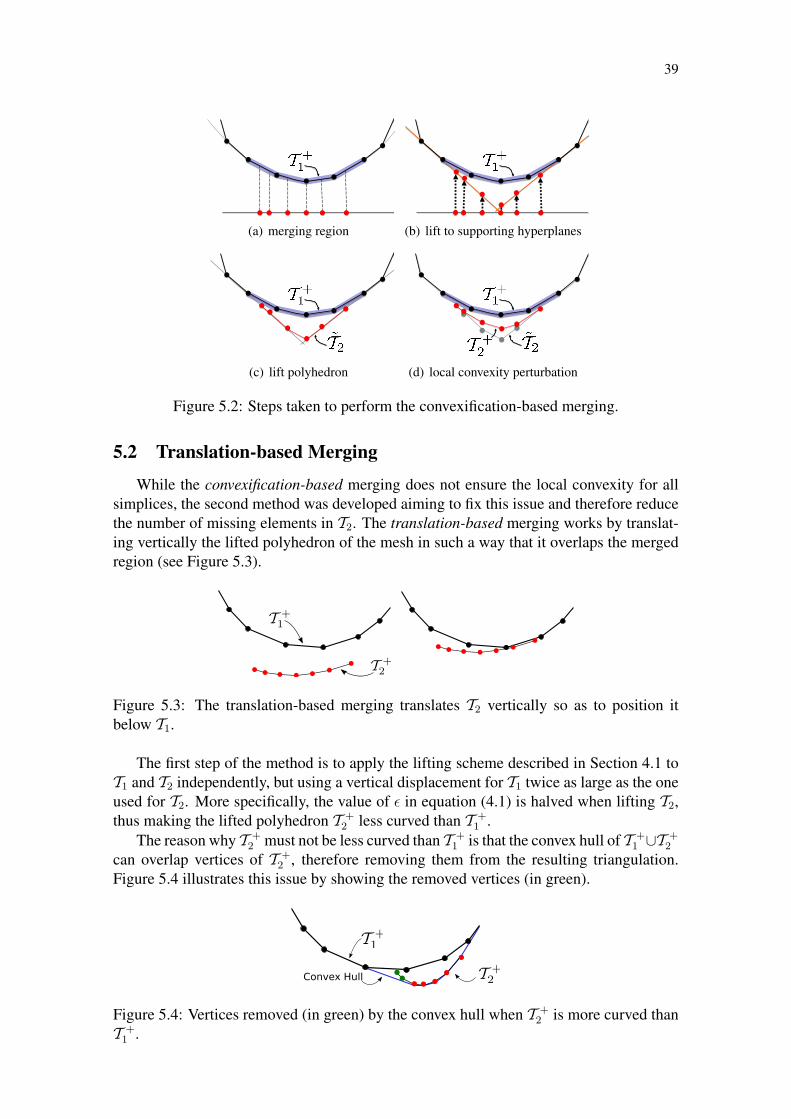
5.1 Convexification-based Merging
The first proposal is called convexification-based merging, and is illustrated in Fig-ure 5.2. Let T1 and T2 be two triangulations and suppose that T2 must be merged with T1
while keeping T1 as unchanged as possible (i.e. we only want to affect a neighborhoodsurrounding T2). We position T2 inside T1 and lift the polyhedron T2 in such a way thatT +
2 is squeezed up between the lifted polyhedron T +1 and the supporting hyperplanes for
those simplices of T +1 are not affected by the merging.
The squeezing process is composed of three steps. First, the d-simplices of S ⊂T1 that do not intersect T2 are identified (Figure 5.2.a) and their supporting hyperplanescomputed (Figure 5.2.b). In the second step, we set the weight of each vertice v of T2 insuch way that the vertice is placed at the highest intersection v between the vertical linepassing through v and the supporting hyperplanes of the d-simplices in S (Figure 5.2.b).This construction results in a polyhedron in Ed+1 that we denote by T2 (Figure 5.2.c).The final step makes the (d − 1)-simplices of T2 locally convex, using a subdivisionprocedure as before. Starting from the d-simplices t
+i ∈ T2 with at least one face on
the boundary of T2, we apply a small vertical perturbation on each vertice opposite tot+i , to position it above the supporting hyperplane of t
+i and bellow T +
1 . We repeat thisprocedure recursively, moving vertices towards the interior of T2 (Figure 5.2.d). Finally,we subdivide absent simplices to force them to appear. Observe that the vertices of T1
inside T2 become internal to the convex hull of T +1 ∪ T +
2 , hence they become redundantand do not appear in the merged triangulation.
Although this approach ensures that only the simplices of T1 affected by the mergingare the ones in S, it is also prone to discard more elements of T2. As opposed to thebreadth-first scheme described in Section 4.1 that propagates a single front while comput-ing weights, the squeezing process lifts T2 by propagating different fronts simultaneouslyfrom the elements at the boundary of the merging region. Therefore, no guarantee can begiven with respect to the local convexity for simplices at the union of two or more fronts,and more non-locally convex faces can appear.
39
(a) merging region (b) lift to supporting hyperplanes
(c) lift polyhedron (d) local convexity perturbation
Figure 5.2: Steps taken to perform the convexification-based merging.
5.2 Translation-based Merging
While the convexification-based merging does not ensure the local convexity for allsimplices, the second method was developed aiming to fix this issue and therefore reducethe number of missing elements in T2. The translation-based merging works by translat-ing vertically the lifted polyhedron of the mesh in such a way that it overlaps the mergedregion (see Figure 5.3).
Figure 5.3: The translation-based merging translates T2 vertically so as to position itbelow T1.
The first step of the method is to apply the lifting scheme described in Section 4.1 toT1 and T2 independently, but using a vertical displacement for T1 twice as large as the oneused for T2. More specifically, the value of � in equation (4.1) is halved when lifting T2,thus making the lifted polyhedron T +
2 less curved than T +1 .
The reason why T +2 must not be less curved than T +
1 is that the convex hull of T +1 ∪T +
2
can overlap vertices of T +2 , therefore removing them from the resulting triangulation.
Figure 5.4 illustrates this issue by showing the removed vertices (in green).
Figure 5.4: Vertices removed (in green) by the convex hull when T +2 is more curved than
T +1 .

40
Once weights have been assigned to vertices in T1 and T2, we displace T +2 vertically
(adding a constant to all weights) until it approaches T +1 from below, as illustrated in
Figure 5.3. As T +2 is less curved than T +
1 , their support hyperplanes tend to be belowT +
1 , thus keeping T2 unchanged after the merging process (including simplices subdividedduring the weight assignment step).
The main drawback of the translation-based method is that it affects more the neigh-borhood of the merged mesh in comparison to the convexification-based method. Whilein the first approach the lifted polyhedron is changed to not affect the neighbors of themerged area, the second one only translates the mesh aiming to overlap the merged area,therefore the convex hull of T +
1 ∪ T +2 end up removing more vertices of T +
1 . Despite thisissue, the vertical translation of T +
2 behaves well in practice, as we show in Chapter 6.
5.3 Fringe
We observed that when merging meshes with different refinement levels the resultingtriangulation often presented badly shaped simplicial elements on the neighborhood of themerged area. Those simplices are automatically inserted by the RT to create a consistentconnectivity on the triangulation. In this section we address this issue by introducing theconcept of fringe, an intermediate triangulation that makes a smoother transition betweenmeshes to be merged together. A fringe is mostly necessary when merging meshes withdistinct refinement levels, since they are prone to generate badly shaped simplices.
Figure 5.5: Fringing process. On the left, we show the two meshes that will be merged,along with the regular grid containing the local density estimates for the meshes. The redcircles mark boundary conditions on the Laplacian Solver. On the right, the smaller meshis merged to a fringe (in blue) that makes a graceful transition between the resolution ofthe internal and external meshes.
The fringing process works as follows: we initially compute an estimate of local den-sity. We assign an average edge length to each vertice, and normalize these values tomake the largest average equal to 1. We then define a regular grid whose resolution isgiven by the smallest edge present in the scene, and place it around the inner mesh. Thedensity estimated for each vertice serve as boundary conditions on this grid, and we runa Laplacian solver to smooth the transition between densities on the inside and on theborder of the grid.
The solution given by the Laplacian solver can be seen as the probability that a verticeon the regular grid should present in a transition mesh. Therefore, we selectively maintainvertices of the grid based on their density estimates. Finally, we construct the fringe bygenerating a Delaunay triangulation of the points that were maintained. We also apply

41
one iteration of Laplacian smoothing to the fringe to make its simplices better shaped.Once the fringe is constructed, we accomplish the merging in two steps: first, we mergethe internal mesh with the fringe, and then merge this result with the outer mesh, as shownin Figure 5.5.
As we will show in Chapter 6 the fringe improves the overall quality of simplices gen-erated by the merging methods, therefore solving the problem of badly shaped simpliceswhen merging meshes with different refinement level.
5.4 Summary
This chapter presented two merging methods developed using WDT. The convexification-based merging that changes the original mesh, but affects the neighborhood of the mergedarea to a lesser extent, and the translation-based merging that keeps the original mesh un-changed while modifies the neighborhood of the merged area more than the first one. Wealso addressed the problem of merging meshes with different refinement level by intro-ducing an intermediate triangulation called fringe.
In Chapter 6 we show applications of the merging methods with both 2D and 3Dmeshes, as well the time required to perform both approaches. The fringe examples willalso be presented, and we show the average quality of triangles to demonstrate its effec-tiveness.

42

43
6 RESULTS AND APPLICATIONS
In order to demonstrate the potential use of the methods proposed in this work, wewill present 2D and 3D examples of the merging approaches mentioned before, and alsoshow how the fringe solves issues related to badly shaped simplices.
The applications were developed using CGAL’s WDT algorithm (BOISSONNAT et al.,2000; TEILLAUD, 1999; FABRI, 2007; CGAL, 2010) to generate triangulations fromvertice coordinates and weights computed by our code. Below we show a series of merg-ing examples containing several triangulations of different characteristics.
The value of � (see equation 4.1 for details) defines how high a vertice will be raisedin order to create a local convexity of a simplice and one of its neighbors. It is clear thathigh values of � will generate a lifted polyhedron with high concavity. The concavity ofthe lifted polyhedron affects the merging method since it has a straight influence over theconvex hull of the meshes. For instance, a high concave mesh is prone to generate morecases of redundant vertices on neighborhood of the merged area. However, if � is toosmall it may cause numerical instabilities.
In our experiments, values for � ranging from 10−4 to 10−8 presented numerical sta-bility and the merging methods yielded fine results. In this chapter, all experiments wereconducted using � = 10−5.
6.1 Merging 2D meshes
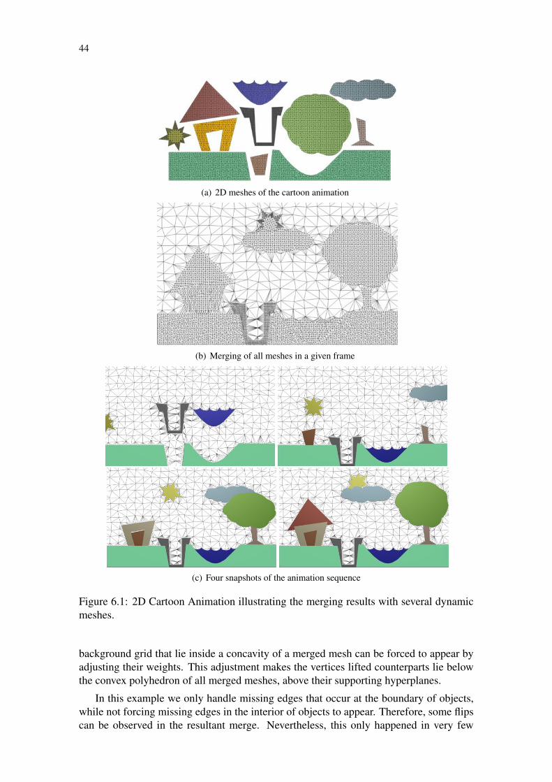
We illustrate the flexibility and capability of merging triangulations with our schemewith a physics-based cartoon animation of 2D meshes. The animation is composed of ascene with several meshes that move inside a background triangulation. The backgroundmesh performs collision detection and simplifies object placement, since we can computethe adjacency between distinct objects by analyzing whether edges in the backgroundgrid connect them. In our implementation the elastic deformation of each object waspre-computed. Figures 6.1(a) and 6.1(b) show the meshes used in the animation and themerging result using the translation-based scheme.
Figure 6.2 shows frames of a simple animation developed to demonstrate the capa-bility of our technique to handle several meshes simultaneously. To perform an examplewith multiple meshes is firstly necessary to define a preference order, since the methodapplies the merging for two meshes on each interaction, then the resulting mesh is usedto merge with the next, following the preference order. The order with which objectsare merged naturally solves the problem of front-to-back alignment. In this example, weprioritize the mesh of the last object merged, thus placing it in front of all the others.
As algorithms to compute the WDT always generate a triangulation for the convexhull of the weighted points, we have to handle concavities explicitly. Vertices in the
44
(a) 2D meshes of the cartoon animation
(b) Merging of all meshes in a given frame
(c) Four snapshots of the animation sequence
Figure 6.1: 2D Cartoon Animation illustrating the merging results with several dynamicmeshes.
background grid that lie inside a concavity of a merged mesh can be forced to appear byadjusting their weights. This adjustment makes the vertices lifted counterparts lie belowthe convex polyhedron of all merged meshes, above their supporting hyperplanes.
In this example we only handle missing edges that occur at the boundary of objects,while not forcing missing edges in the interior of objects to appear. Therefore, some flipscan be observed in the resultant merge. Nevertheless, this only happened in very few

45
Figure 6.2: Figures showing several meshes being merged.
cases.
6.2 Merging 3D meshes
(a) Convexification-based merging (b) Translation-based merging
Figure 6.3: Merging the aorta artery tetrahedral mesh with a tetrahedral decomposition ofa sphere. a) Convexification-based merging, 4.63% missing edges; b) Translation-basedmerging, no absent edges.
This second set of experiments demonstrates the interaction between tetrahedral meshes.Due to occlusion, screenshots of the merging result in 3D hardly convey the strength ofour connectivity oblivious technique. Therefore, we present renderings of cutaway sec-tions of the models. In addition, we validate merging results initially without the fringestrategy, since we want to show the affected tetrahedra closer to the merging region.
The first experiment is composed of a moving tetrahedral sphere passing througha mesh of the aorta artery. Figures 6.3 show the sphere merged inside the aorta us-ing both the convexification and translation-based merging schemes. Even though theconvexification-based approach impacts a smaller neighborhood around the merging re-gion, more absent simplices tend to be generated with this technique.
In Figure 6.3(b) we observe that some vertices in the neighborhood of the spherewere removed (became redundant) when using the translation-based merging scheme.However, no missing simplices were identified in the translation-based approach, while4.63% of missing simplices were found and subdivided using the convexification-basedmerging (all inside the sphere).
Table 6.1 lists the number of vertices in each mesh, as well as the time to performweight computation and the triangulation. Table 6.2 shows the merging time using both

46
Dataset Vertices Weight Computation TriangulationAorta 9529 45.05 1259.52Sphere 58 0.094 12.28Grid 1 50480 305.15 6633.47Rocker 10713 53.24 1662.97Rod 3098 10.24 870.40Valve 3857 16.38 882.68Grid 2 8371 30.72 744.14Buddha 27975 178.17 5230.59
Table 6.1: Mesh data and WDT computation (all times in ms)
Merging Meshes Convexification-based Translation-basedAorta-Sphere 53.24 63.48
Grid 1-Rocker 33062.91 38082.17Rocker-Arm 528.38 503.80
Valve-Rod 223.23 196.69Grid 2-Buddha 61526.01 665647.87
Table 6.2: Merging Times (all times in ms)
approaches (observe that in the second example we use three merges to compute the finalresult).
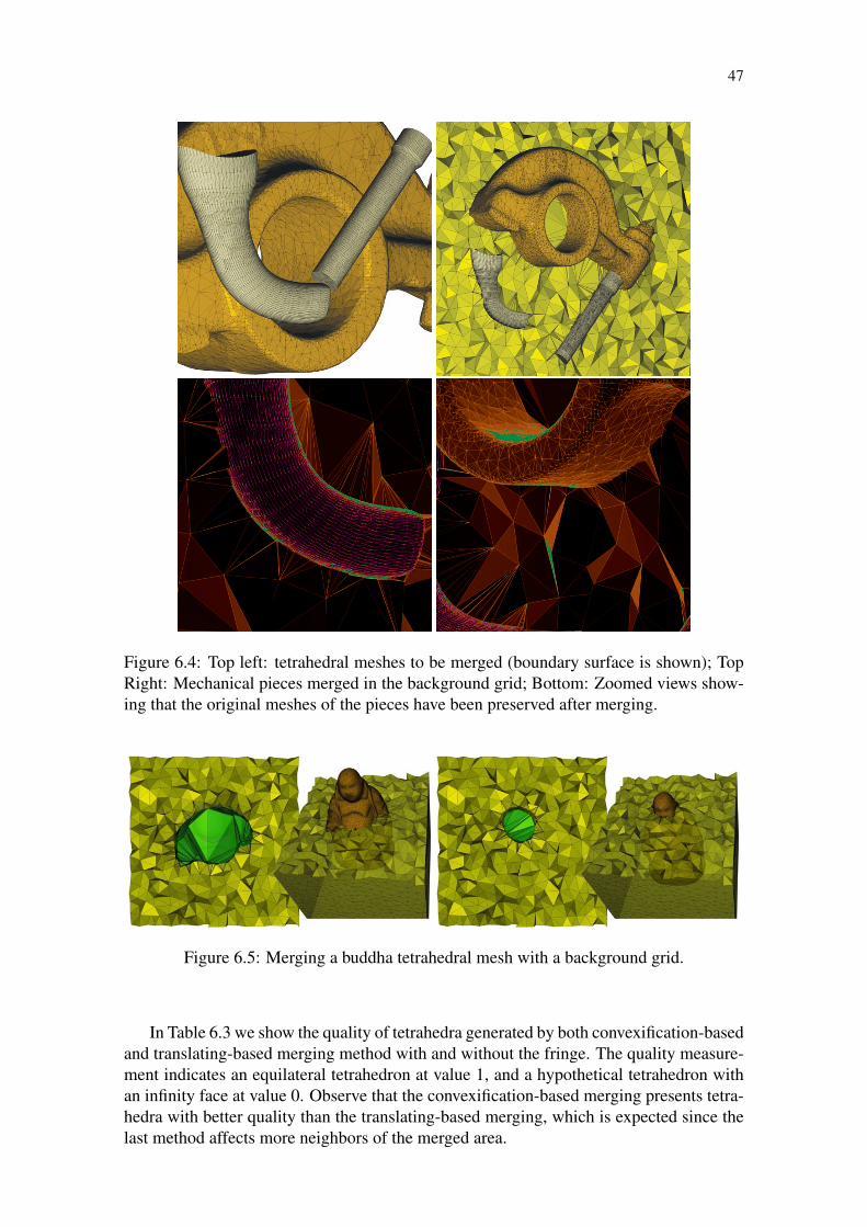
Figure 6.4 illustrates the capability of our technique to handle large and complex tetra-hedral meshes with arbitrary topology. The topmost left image in Figure 6.4 shows thetetrahedral meshes (only boundary faces are shown) of three mechanical pieces mergedinside a cubic background grid, as illustrated in the topmost right image. Notice fromthe close-ups that the anisotropy of the gray meshes has been preserved after merging.In fact, no missing simplices (thus no new vertices) have appeared after merging thesemodels using the translation-based scheme.
Another example with complex tetrahedra shows that our approach is able to handlemeshes with distinct levels of refinement. Figure 6.5 shows the merge of a buddah datasetwith a background grid, notice that the internal tetrahedra of the buddha have not beenrefined, therefore the WDT fills the inner region.
6.3 Fringe
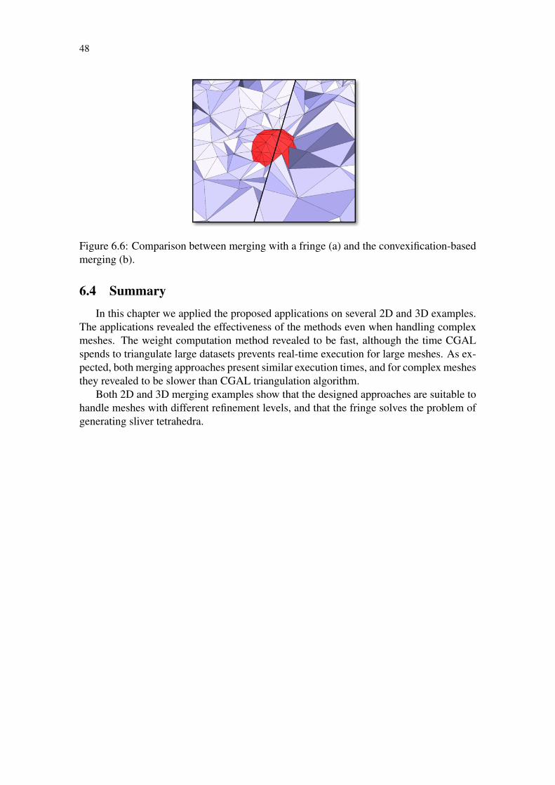
The fringe was developed to ensure a smoother transition between the resolution of thetwo meshes merged together, thus minimizing the occurrence of elongated, low-qualitytetrahedra. Besides, in practice it revealed to improve the overall quality of the mergedarea. Figure 6.6 illustrates the same merge shown in Figure 6.3, only this time using afringe to smooth the transition between the aorta and the sphere.
Merge Method Without fringe With fringeConvexification-based 0.48 0.74
Translation-based 0.44 0.72
Table 6.3: Comparison showing the tetrahedra quality of merging methods with and with-out fringe.
47
Figure 6.4: Top left: tetrahedral meshes to be merged (boundary surface is shown); TopRight: Mechanical pieces merged in the background grid; Bottom: Zoomed views show-ing that the original meshes of the pieces have been preserved after merging.
Figure 6.5: Merging a buddha tetrahedral mesh with a background grid.
In Table 6.3 we show the quality of tetrahedra generated by both convexification-basedand translating-based merging method with and without the fringe. The quality measure-ment indicates an equilateral tetrahedron at value 1, and a hypothetical tetrahedron withan infinity face at value 0. Observe that the convexification-based merging presents tetra-hedra with better quality than the translating-based merging, which is expected since thelast method affects more neighbors of the merged area.
48
Figure 6.6: Comparison between merging with a fringe (a) and the convexification-basedmerging (b).
6.4 Summary
In this chapter we applied the proposed applications on several 2D and 3D examples.The applications revealed the effectiveness of the methods even when handling complexmeshes. The weight computation method revealed to be fast, although the time CGALspends to triangulate large datasets prevents real-time execution for large meshes. As ex-pected, both merging approaches present similar execution times, and for complex meshesthey revealed to be slower than CGAL triangulation algorithm.
Both 2D and 3D merging examples show that the designed approaches are suitable tohandle meshes with different refinement levels, and that the fringe solves the problem ofgenerating sliver tetrahedra.
49
7 CONCLUSIONS AND FUTURE WORK
This dissertation proposed a novel way of calculating weights of vertices to build aconformal WDT. While numerous approaches use a linear system (Cignoni; De Floriani,1998; BALAVEN et al., 2002) to determine the weights, we developed an algorithmicalsolution based on a breadth-first traversal of the mesh, and using fundamental mathemat-ical concepts of WDTs. This solution proved to be fast and suitable for several applica-tions, and opens a field to be further explored.
A remarkable aspect of our approach is that, despite its simplicity, it is able to handleand merge complex simplicial meshes without managing connectivity explicitly, as it isusually done with conventional Delaunay methods. However, it is important to point outthat there are significant differences between our approach and Delaunay-based schemes.Our technique starts from a set of triangulations, whereas Delaunay-based methods build atriangulation from curves and surfaces constraining the domain of interest. The differencebetween the two methodologies becomes more evident when dealing with anisotropicmeshes.
Although anisotropic versions of Delaunay triangulations and constrained Delaunaytriangulations have been used to handle anisotropic meshes (BOROUCHAKI et al., 1997).However, such techniques demand either tensor estimation to define the anisotropy or anexplicit manipulation of constraints. This can become as complex as the connectivitymanagement during merging operations. In fact, our approach can be seen as a first steptoward a new framework for connectivity oblivious mesh representation using the idea ofregular triangulations.
In this work, we also proposed different methods to merge simplicial complexes with-out the need to explicitly manage connectivity information. The merging schemes pre-sented gave very satisfactory results, especially regarding algorithm stability and the lo-cality of mesh updates. While the translation-based merging works by translating verti-cally the lifted polyhedron of the mesh in such a way that it overlaps the merged region,the convexification-based merging squeezes up the lifted polyhedron of the mesh betweenthe lifted polyhedron of the merged area and the supporting hyperplanes of the simpliceson the border.
In some applications, the translation-based merging scheme may affect a wide neigh-borhood around the merging region, making many vertices redundant. Although one canalways reinstate missing vertices by vertically displacing then beneath the convex hullof lifted points, checking for redundancy can become costly. Plane projection plus con-vexification can indeed ensure local mesh updates for the background grid. However,the number of internal missing simplices exceeded 10% in one of our experiments (ourworst case), which can be unacceptable in applications where internal meshes must bepreserved.

50
The large number of absent elements, in many cases, is due to numerical instabilities,as the cavity between the convex hull and the support planes can become too narrow. Thismakes it numerically difficult to convexify the lifted polyhedron with vertical perturba-tions. If an excessively vertical perturbation is applied to a vertice, numerical predicatestend to consider adjacent simplices as coplanar, violating what is known as the generalposition hypothesis. This makes it difficult to predict which vertices will be seen as copla-nar.
The convexification-based could be improved with some effort on creating a new wayto squeeze the lifted polyhedra to reduce this issue could reduce the occurrence of thisissue. While the translation-based merging ensures the maintenance of the simplices atthe cost of having a heavier effect on the the neighborhood of the merged area. A studyconducted to define a better convexity of the lifted polyhedron could improve the results,since when the polyhedron is more concave than the merged area, some of its simplicesbecome redundant, and when the polyhedron is more convex it impacts on the neighbor-hood.
We solved the issue with badly shaped simplices inserted when merging meshes withdifferent refinement levels by introducing the fringe. The fringe worked by improvingthe quality of tetrahedra created by both merging approaches. Nevertheless, in practiceto use the fringe requires that the merged area has enough space so that vertices of thefringe can smooth the transitions, otherwise it will not present satisfactory results and caneven give rise to badly shaped tetrahedra. Therefore, the size a fringe will depend on bothrefinement level and size of the meshes being merged.
The examples developed in this work validated the proposed techniques. They clearlyshow the merging process working well for several kinds of meshes. Additionally, theydemonstrated that the fringe, on its turn, solves problems of meshes with different refine-ment levels and improves the quality of simplices. Finally, they made possible to observethat the computing weights method is both fast and usable with other applications.
Since WDTs generates triangulations with their convex hull, the merging methods arebetter suitable to convex meshes. While for convex meshes the result presents triangula-tions that match the originals, for concave datasets it is necessary a post processing stepto remove simplices created due to the convex hull. In some of our examples we had todeal with this issue, and depending on the mesh surface it can be a painful task.
Regarding execution time, the weight computation algorithm revealed to be efficienteven with large datasets, nevertheless, to build the corresponding triangulation. It is nec-essary to use CGAL’s WDT method, which prevents real-time executions. The mergingmethods proved to be faster than the triangulation for small datasets, however, for largemeshes they become slower. The method used to find the merged area explains this be-havior, since after the area is found our approach presents O(n) complexity.
In the future, we would like to further explore our weight assignment technique, tobetter enforce local convexity of the lifted polyhedron. Also, an interesting avenue forfuture research is to combine our framework with numerical simulation applications. Ourmerging schemes generate high quality simplices, and we believe it should be possible tocouple it with existing numerical models.
An important study could be conducted to analyze the influence of � on the methodto assign weights and on the merging techniques. Since there is a trade-off betweennumerical stability and better results, this study could point an optimal value of � thatavoids missing simplices while keeps numerical stability.
51
REFERENCES
AHN, M.; LEE, S. Mesh Metamorphosis with Topology Transformations. pg, Los Alami-tos, CA, USA, v.00, p.481, 2002.
AHN, M.; LEE, S.; SEIDEL, H.-P. Connectivity transformation for mesh metamorpho-sis. In: SGP ’04: PROCEEDINGS OF THE 2004 EUROGRAPHICS/ACM SIGGRAPHSYMPOSIUM ON GEOMETRY PROCESSING, 2004, New York, NY, USA. . . . ACMPress, 2004. p.75–82.
AMENTA, N.; BERN, M. Surface reconstruction by Voronoi filtering. In: SCG ’98:PROCEEDINGS OF THE FOURTEENTH ANNUAL SYMPOSIUM ON COMPUTA-TIONAL GEOMETRY, 1998, New York, NY, USA. . . . ACM, 1998. p.39–48.
AMENTA, N.; BERN, M.; KAMVYSSELIS, M. A new Voronoi-based surface recon-struction algorithm. In: SIGGRAPH ’98: PROCEEDINGS OF THE 25TH ANNUALCONFERENCE ON COMPUTER GRAPHICS AND INTERACTIVE TECHNIQUES,1998, New York, NY, USA. . . . ACM, 1998. p.415–421.
AMENTA, N.; CHOI, S.; KOLLURI, R. The Power Crust. Computatinal Geometry,[S.l.], v.19, p.127–153, 2001.
AURENHAMMER, F. Power Diagrams: properties, algorithms and applications. SIAM
J. Comput., [S.l.], v.16, n.1, p.78–96, 1987.
AURENHAMMER, F. Voronoi diagrams—a survey of a fundamental geometric datastructure. ACM Comput. Surv., New York, NY, USA, v.23, n.3, p.345–405, 1991.
AURENHAMMER, F.; IMAI, H. Geometric relations among Voronoi diagrams. In: AN-NUAL SYMPOSIUM ON THEORETICAL ASPECTS OF COMPUTER SCIENCESON STACS 87, 4., 1987, London, UK. . . . Springer-Verlag, 1987. p.53–65.
BALAVEN, S. et al. Conforming Orthogonal Meshes. [S.l.]: INRIA - Sophia Antipolis,2002. (4404).
BERG, M. de et al. Computational Geometry: algorithms and applications. 2 ed. [S.l.]:Springer-Verlag, 2000. 367p.
BOISSONNAT, J.-D. et al. Triangulations in CGAL (extended abstract). In: SCG ’00:PROCEEDINGS OF THE SIXTEENTH ANNUAL SYMPOSIUM ON COMPUTA-TIONAL GEOMETRY, 2000, New York, NY, USA. . . . ACM, 2000. p.11–18.

52
BOISSONNAT, J.-D.; OUDOT, S. Provably good sampling and meshing of surfaces.Graphical Models, [S.l.], v.67, p.405–451, 2005.
BOROUCHAKI, H. et al. Delaunay mesh generation governed by metric specifications.Part I. Algorithms. Finite Elements in Analysis and Design, [S.l.], v.25, p.61–83, 1997.
BREEN, D. et al. 3D Metamorphosis Between Different Types of Geometric Models.In: CHALMERS, A.; RHYNE, T.-M. (Ed.). EG 2001 Proceedings. [S.l.]: BlackwellPublishing, 2001. v.20(3), p.36–48.
CASTRO, P. M. M. de et al. Filtering Relocations on a Delaunay Triangulation. Com-
puter Graphics Forum, [S.l.], v.28, n.5, p.1465–1474, 2009.
CGAL. Computational Geometry Algorithms Library. [Online; accessed 21-January-2007].
CHENG, S.-W.; DEY, T. K.; RAMOS, E. A. Delaunay refinement for piecewise smoothcomplexes. In: SODA ’07: PROCEEDINGS OF THE EIGHTEENTH ANNUAL ACM-SIAM SYMPOSIUM ON DISCRETE ALGORITHMS, 2007, Philadelphia, PA, USA.. . . Society for Industrial and Applied Mathematics, 2007. p.1096–1105.
CHENG, S.-W.; DEY, T.; RAY, T. Weighted Delaunay Refinement for Polyhedrawith Small Angles. In: INTERNATIONAL MESHING ROUNDTABLE, 14., 2005. . . .
Springer-Verlag:, 2005. p.11–14.
CHENG, S.-W. et al. Sliver exudation. In: SCG ’99: PROCEEDINGS OF THE FIF-TEENTH ANNUAL SYMPOSIUM ON COMPUTATIONAL GEOMETRY, 1999, NewYork, NY, USA. . . . ACM Press, 1999. p.1–13.
CHENG, S.-W. et al. Sampling and meshing a surface with guaranteed topology andgeometry. In: SCG ’04: PROCEEDINGS OF THE TWENTIETH ANNUAL SYMPO-SIUM ON COMPUTATIONAL GEOMETRY, 2004, New York, NY, USA. . . . ACM,2004. p.280–289.
CHEW, L. P. Constrained Delaunay triangulations. In: SCG ’87: PROCEEDINGS OFTHE THIRD ANNUAL SYMPOSIUM ON COMPUTATIONAL GEOMETRY, 1987,New York, NY, USA. . . . ACM, 1987. p.215–222.
CHRYSANTHOU, Y.; SLATER, M. Computing dynamic changes to BSP trees. Com-
puter Graphics Forum, [S.l.], v.11, n.3, p.C321–C332, September 1992.
Cignoni, P.; De Floriani, L. Power Diagram Depth Sorting. In: CANADIAN CONFER-ENCE ON COMPUTATIONAL GEOMETRY, 10., 1998, Montréal, Québec, Canada.Proceedings. . . School of Computer Science: McGill University, 1998. p.88–89.
COHEN, J. et al. Simplification envelopes. In: SIGGRAPH ’96: PROCEEDINGS OFTHE 23RD ANNUAL CONFERENCE ON COMPUTER GRAPHICS AND INTERAC-TIVE TECHNIQUES, 1996, New York, NY, USA. . . . ACM, 1996. p.119–128.
CUADROS-VARGAS, A. J. et al. Imesh: an image based quality mesh generation tech-nique. Computer Graphics and Image Processing, Brazilian Symposium on, LosAlamitos, CA, USA, v.0, p.341–348, 2005.

53
DANCIGER, J.; DEVADOSS, S. L.; SHEEHY, D. Compatible triangulations and pointpartitions by series-triangular graphs. Comput. Geom. Theory Appl., Amsterdam, TheNetherlands, The Netherlands, v.34, n.3, p.195–202, 2006.
DELAUNAY, B. N. Sur la sphère vide. 1934.
DELOERA, J.; STURMFELS, J.; THOMAS, R. Gröbner Bases and Triangulations of theSecond Hypersimplex. Combinatorica, [S.l.], v.15, n.3, p.409–424, 1995.
DEVILLERS, O. et al. Checking the convexity of polytopes and the planarity of subdivi-sions. Computational Geometry, [S.l.], v.11, p.187–208, 1998.
EDELSBRUNNER, H. An acyclicity theorem for cell complexes in d dimensions. In:SCG ’89: PROCEEDINGS OF THE FIFTH ANNUAL SYMPOSIUM ON COMPUTA-TIONAL GEOMETRY, 1989, New York, NY, USA. . . . ACM, 1989. p.145–151.
EDELSBRUNNER, H. Deformable Smooth Surface Design. Discrete & Computational
Geometry, [S.l.], v.21, n.1, p.87–115, 1999.
EDELSBRUNNER, H. Geometry and Topology for Mesh Generation. [S.l.]: Cam-bridge University Press, 2001.
EDELSBRUNNER, H.; GUOY, D. An Experimental Study of Sliver Exudation. 2001.
EDELSBRUNNER, H.; SEIDEL, R. Voronoi diagrams and arrangements. Discrete Com-
put. Geom., [S.l.], v.1, p.25–44, 1986.
EDELSBRUNNER, H.; SHAH, S. Incremental Topological Flipping Works for RegularTriangulations. Algorithmica, [S.l.], v.15, p.223–241, 1996.
FABRI, A. Voronoi Diagrams in CGAL, the Computational Geometry Algorithms Li-brary. In: ISVD ’07: PROCEEDINGS OF THE 4TH INTERNATIONAL SYMPOSIUMON VORONOI DIAGRAMS IN SCIENCE AND ENGINEERING, 2007, Washington,DC, USA. . . . IEEE Computer Society, 2007. p.8–14.
FLOATER, M.; C.GOTSMAN. How to morph tilings injectively. J. Comput. Appl.
Math., Amsterdam, The Netherlands, The Netherlands, v.101, n.1-2, p.117–129, 1999.
GROSS, M.; PFISTER, H. (Ed.). Point-Based Graphics. [S.l.]: Morgan Kaufmann,2007.
GUIBAS, L. Kinetic data structures. In: HANDBOOK OF DATA STRUCTURES ANDAPPLICATIONS, 2004. . . . CRC Press, 2004.
LABELLE, F. Sliver removal by lattice refinement. In: SCG ’06: PROCEEDINGS OFTHE TWENTY-SECOND ANNUAL SYMPOSIUM ON COMPUTATIONAL GEOME-TRY, 2006, New York, NY, USA. . . . ACM, 2006. p.347–356.
LEE, A. W. F. et al. Multiresolution mesh morphing. In: SIGGRAPH ’99: PROCEED-INGS OF THE 26TH ANNUAL CONFERENCE ON COMPUTER GRAPHICS ANDINTERACTIVE TECHNIQUES, 1999, New York, NY, USA. . . . ACM Press/Addison-Wesley Publishing Co., 1999. p.343–350.

54
LUEBKE, D. et al. Level of Detail for 3D Graphics. New York, NY, USA: ElsevierScience Inc., 2002.
LUQUE, R.; COMBA, J. L. D.; FREITAS, C. M. D. Broad-Phase Colision DetectionUsing Semi-Adjusting BSP-Trees. In: ACM SIGGRAPH INTERACTIVE 3D GRAPH-ICS AND GAMES - I3D 2005, 2005. Proceedings. . . [S.l.: s.n.], 2005. p.179–186.(1595930132).
MASADA, T.; IMAI, H.; IMAI, K. Enumeration of regular triangulations. In: SCG’96: PROCEEDINGS OF THE TWELFTH ANNUAL SYMPOSIUM ON COMPUTA-TIONAL GEOMETRY, 1996, New York, NY, USA. . . . ACM Press, 1996. p.224–233.
MEHLHORN, K. et al. Checking geometric programs or verification of geometric struc-tures. In: ANNU. ACM SYMPOS. COMPUT. GEOM., 12., 1996. Proceedings. . .
[S.l.: s.n.], 1996. p.159–165.
NAYLOR, B. F. Interactive solid geometry via partitioning trees. In: GRAPHICS IN-TERFACE ’92, 1992. Proceedings. . . [S.l.: s.n.], 1992. p.11–18.
NONATO, L. G. et al. Beta-Connection: generating a family of models from planar crosssections. ACM Transactions on Graphics, [S.l.], v.24, n.4, p.1239–1258, 2005.
PARUS, J.; KOLINGEROVá, I. Morphing of meshes with attributes. In: SCCG ’04: PRO-CEEDINGS OF THE 20TH SPRING CONFERENCE ON COMPUTER GRAPHICS,2004, New York, NY, USA. . . . ACM Press, 2004. p.73–81.
PIRES, F. B. Triangulações regulares e aplicações. 2008. Dissertação (Mestrado emCiência da Computação) — Instituto de Ciências Matemáticas e de Computação - USP.
RUPPERT, J. A new and simple algorithm for quality 2-dimensional mesh generation. In:SODA ’93: PROCEEDINGS OF THE FOURTH ANNUAL ACM-SIAM SYMPOSIUMON DISCRETE ALGORITHMS, 1993, Philadelphia, PA, USA. . . . Society for Industrialand Applied Mathematics, 1993. p.83–92.
SCHREINER, J. et al. Inter-surface mapping. In: SIGGRAPH ’04: ACM SIGGRAPH2004 PAPERS, 2004, New York, NY, USA. . . . ACM Press, 2004. p.870–877.
SHEWCHUK, J. Delaunay Refinement Algorithms for Triangular Mesh Generation.Computational Geometry: theory and applications, [S.l.], v.22, n.2-3, p.21–74, 2002.
SURAZHSKY, V.; GOTSMAN, C. Morphing Stick Figures Using Optimized CompatibleTriangulations. In: PG ’01: PROCEEDINGS OF THE 9TH PACIFIC CONFERENCEON COMPUTER GRAPHICS AND APPLICATIONS, 2001, Washington, DC, USA. . . .
IEEE Computer Society, 2001. p.40.
SURFACE SIMPLIFICATION USING QUADRIC ERROR METRICS, 1997, New York,NY, USA. . . . ACM Press/Addison-Wesley Publishing Co., 1997. p.209–216.
TEILLAUD, M. Three Dimensional Triangulations in CGAL. 1999.
TORRES, E. Optimization of the Binary Space Partition Algorithm (BSP) for the Visual-ization of Dynamic Scenes. In: EUROGRAPHICS ’90, 1990. . . . North-Holland, 1990.p.507–518.

55
TOURNOIS, J. et al. Interleaving Delaunay refinement and optimization for practicalisotropic tetrahedron mesh generation. ACM Trans. Graph., New York, NY, USA, v.28,n.3, p.1–9, 2009.
TOURNOIS, J.; SRINIVASAN, R.; ALLIEZ, P. Perturbing Slivers in 3D Delaunay
Meshes. 2009.
VIGO, M.; PLA, N.; COTRINA, J. Regular triangulations of dynamic sets of points.Comput. Aided Geom. Des., Amsterdam, The Netherlands, The Netherlands, v.19, n.2,p.127–149, 2002.
ZORIN, D.; SCHRöDER, P.; SWELDENS, W. Interpolating Subdivision for meshes witharbitrary topology. In: SIGGRAPH ’96: PROCEEDINGS OF THE 23RD ANNUALCONFERENCE ON COMPUTER GRAPHICS AND INTERACTIVE TECHNIQUES,1996, New York, NY, USA. . . . ACM Press, 1996. p.189–192.