mercury tm 2000, 3000 & 3500 - intelligent motion control tm 2000, 3000 & 3500 ... m2000 and...
TRANSCRIPT

Mercury TM 2000, 3000 & 3500SSmmaarrtt PPrrooggrraammmmaabbllee EEnnccooddeerr SSyysstteemmssIInnssttaallllaattiioonn MMaannuuaall aanndd RReeffeerreennccee GGuuiiddee
Manual No. IM-M2000&3000 Rev i

M2000 and M3000 are CE compliant. M3500 CE compliance is pending
IInnttrroodduuccttiioonnMicroE Systems was founded to advance encoder technology toa level never before achieved. Our objective was to design encodersystems that would be small enough to fit into densely packed OEMequipment designs, affordable enough for cost-sensitive applicationsand easy enough to enable installation, setup and alignment byassemblers with little training. We are pleased to say that all ofthese goals have been realized with the introduction of the Mercuryfamily of encoders.
Sensor shownactual size
M10
PPaatteennttssCovered by the following patents: US 5,991,249; EP 895,239; JP 3,025,237; US6,897,435; and EP 1,451,933. Additional patents and patents pending may apply.
PPrreeccaauuttiioonnssFollow standard ESD precautions. Turn power off before connecting the sensor.Do not touch the electrical pins without static protection such as a groundedwrist strap.
Do not touch the glass scale unless you are wearing talc-free gloves or fingercots. Please read this installation manual for full instructions.
LLAASSEERR SSAAFFEETTYY IINNFFOORRMMAATTIIOONN:: MMeerrccuurryy && CChhiippEEnnccooddeerr
1
2
This product is sold solely for use as a component (or replacement) in an electronic product; therefore it is notrequired to, and does not comply with, 21 CFR 1040.10 and 1040.11 which pertain to complete laserproducts. The manufacturer of the complete system-level electronic product is responsible for complying with 21CFR 1040.10 and 1040.11 and for providing the user with all necessary safety warnings and information.MicroE encoders contain an infrared laser diode or diodes. Emitted invisible laser radiation levels have beenmeasured to be within the CDRH Class 1 range, which is not considered hazardous; however, to minimizeexposure to the diverging beam, the encoder sensor should be installed in its operational configuration in closeproximity to the encoder scale before power is applied.
• Invisible laser radiation; wavelength: 850 nm• Max power 2.4 mW CW (4.8 mW CW for Mercury II™)• CAUTION – The use of optical instruments with this product will increase eye hazard. DO NOT VIEW
DIRECTLY WITH OPTICAL INSTRUMENTS (MICROSCOPES, EYE LOUPES OR MAGNIFIERS).• All maintenance procedures such as cleaning must be performed with the MicroE encoder turned off.• Do not insert any reflective surface into the beam path when the encoder is powered.• Do not attempt to service the MicroE encoder.
INVISIBLE LASER RADIATION DO NOT VIEW DIRECTLY WITH OPTICAL
INSTRUMENTS (MICROSCOPES, EYE LOUPES OR
MAGNIFIERS)

TTaabbllee OOff CCoonntteennttssSYSTEM ILLUSTRATION PAGE
Encoder with Linear scale 2Encoder with Rotary scale 3
INSTALLATION INSTRUCTIONSEncoder System Mounting - Linear 4 Encoder System Alignment - Linear 5Centering the Index & Calibration - Linear 5Encoder System Mounting - Rotary 6Encoder System Alignment - Rotary 7Centering the Index & Calibration - Rotary 7
REFERENCE SECTIONInstallation of Linear Scales 8Grounding Instructions 9Recommendations for Power 9Recommended Interface Termination 9Customer Interface Cable Requirements 10 SmartPrecisionTM Module Mounting Options 11Declaration of CE Conformance 11
ENCODER TROUBLESHOOTINGSelected Topics 12Cleaning Scales 12Contact MicroE Systems Back Cover
Page 1
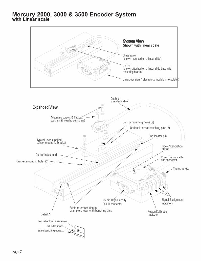
Mercury 2000, 3000 & 3500 Encoder System with Linear scale
EExxppaannddeedd VViieeww
Scale benching edge
End locator pin
End index mark
Sensor mounting holes (2)
Bracket mounting holes (2)
Optional sensor benching pins (3)
Double shielded cable
Center index mark
Typical user-supplied sensor mounting bracket
Top reflective linear scale
Detail A
15 pin High Density D-sub connector
Thumb screw
Index / Calibration button
Power/Calibrationindicator
Mounting screws & flatwashers (2 needed per screw)
SSyysstteemm VViieewwShown with linear scale
Glass scale (shown mounted on a linear slide)
Sensor(shown attached on a linear slide base with mounting bracket)
SmartPrecisionTM electronics module (interpolator)
Page 2
Scale reference datum; example shown with benching pins
Cover: Sensor cableand connector
Signal & alignment indicators
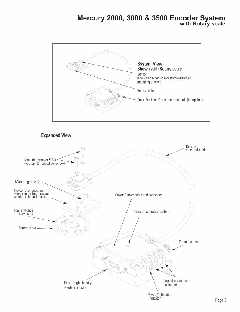
Mercury 2000, 3000 & 3500 Encoder Systemwith Rotary scale
Double shielded cable
Thumb screw
SSyysstteemm VViieewwShown with Rotary scaleSensor(shown attached to a customer-supplied mounting bracket)
Rotary scale
SmartPrecisionTM electronics module (interpolator)
EExxppaannddeedd VViieeww
Rotary scale
Mounting hole (2)
Top reflectiverotary scale
15 pin High Density D-sub connector
Index / Calibration button
Cover: Sensor cable and connector
Page 3
Typical user-supplied sensor mounting bracketwould be located here
Power/Calibrationindicator
Signal & alignment indicators
Mounting screws & flatwashers (2 needed per screw)
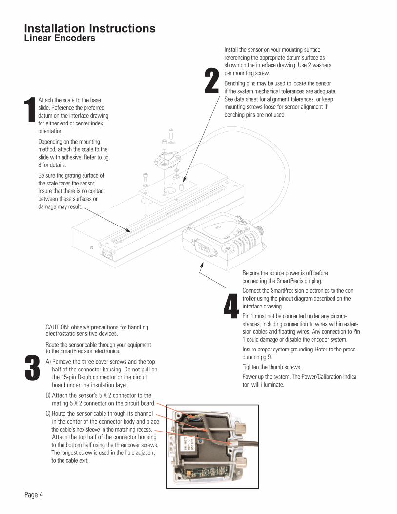
Installation InstructionsLinear Encoders
12
Attach the scale to the baseslide. Reference the preferreddatum on the interface drawingfor either end or center indexorientation.
Depending on the mountingmethod, attach the scale to theslide with adhesive. Refer to pg.8 for details.
Be sure the grating surface ofthe scale faces the sensor. Insure that there is no contactbetween these surfaces or damage may result.
Be sure the source power is off before connecting the SmartPrecision plug.
Connect the SmartPrecision electronics to the con-troller using the pinout diagram described on theinterface drawing.
Pin 1 must not be connected under any circum-stances, including connection to wires within exten-sion cables and floating wires. Any connection to Pin1 could damage or disable the encoder system.
Insure proper system grounding. Refer to the proce-dure on pg 9.
Tighten the thumb screws.
Power up the system. The Power/Calibration indica-tor will illuminate.
4
Page 4
3
CAUTION: observe precautions for handlingelectrostatic sensitive devices.
Route the sensor cable through your equipment to the SmartPrecision electronics.
A) Remove the three cover screws and the top half of the connector housing. Do not pull on the 15-pin D-sub connector or the circuit board under the insulation layer.
B) Attach the sensor's 5 X 2 connector to the mating 5 X 2 connector on the circuit board.
C) Route the sensor cable through its channel in the center of the connector body and place the cable's hex sleeve in the matching recess.Attach the top half of the connector housingto the bottom half using the three cover screws.The longest screw is used in the hole adjacent to the cable exit.
Install the sensor on your mounting surface referencing the appropriate datum surface asshown on the interface drawing. Use 2 washersper mounting screw.
Benching pins may be used to locate the sensor if the system mechanical tolerances are adequate.See data sheet for alignment tolerances, or keepmounting screws loose for sensor alignment ifbenching pins are not used.
Installation InstructionsLinear Encoders
5
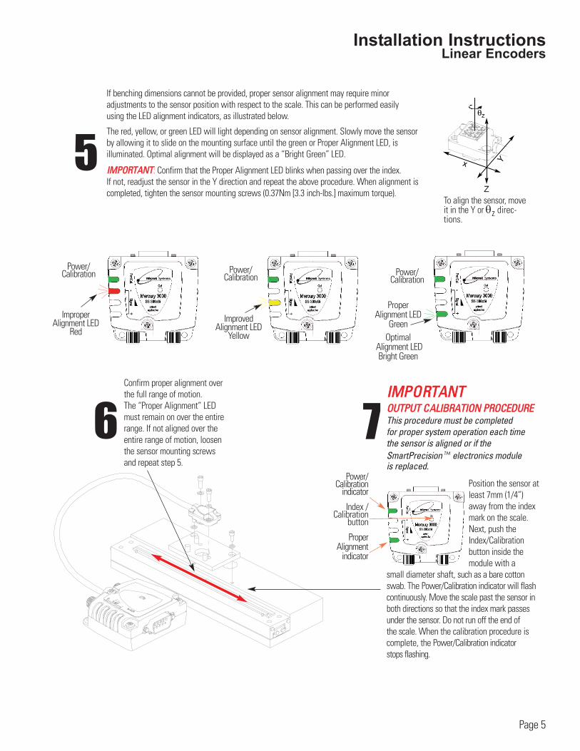
If benching dimensions cannot be provided, proper sensor alignment may require minor adjustments to the sensor position with respect to the scale. This can be performed easily using the LED alignment indicators, as illustrated below.
The red, yellow, or green LED will light depending on sensor alignment. Slowly move the sensorby allowing it to slide on the mounting surface until the green or Proper Alignment LED, is illuminated. Optimal alignment will be displayed as a “Bright Green” LED.
IIMMPPOORRTTAANNTT: Confirm that the Proper Alignment LED blinks when passing over the index. If not, readjust the sensor in the Y direction and repeat the above procedure. When alignment iscompleted, tighten the sensor mounting screws (0.37Nm [3.3 inch-lbs.] maximum torque).
6Confirm proper alignment overthe full range of motion. The “Proper Alignment” LEDmust remain on over the entirerange. If not aligned over theentire range of motion, loosenthe sensor mounting screwsand repeat step 5.
x Y
Z
θz
To align the sensor, moveit in the Y or θz direc-tions.
Page 5
IIMMPPOORRTTAANNTTOOUUTTPPUUTT CCAALLIIBBRRAATTIIOONN PPRROOCCEEDDUURREEThis procedure must be completed for proper system operation each time the sensor is aligned or if theSmartPrecision TM electronics module is replaced.
Position the sensor atleast 7mm (1/4”)away from the indexmark on the scale.Next, push theIndex/Calibration button inside the module with a
small diameter shaft, such as a bare cottonswab. The Power/Calibration indicator will flashcontinuously. Move the scale past the sensor inboth directions so that the index mark passesunder the sensor. Do not run off the end of the scale. When the calibration procedure is complete, the Power/Calibration indicatorstops flashing.
7Power/
Calibrationindicator
Index /Calibration
button
Proper Alignment
indicator
Improper Alignment LED
Red
Power/Calibration
Power/Calibration Power/
Calibration
ImprovedAlignment LED
Yellow
Proper Alignment LED
GreenOptimal
Alignment LED Bright Green
Installation InstructionsRotary Encoders
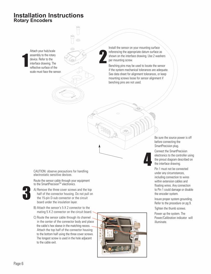
Attach your hub/scaleassembly to the rotarydevice. Refer to theinterface drawing. Thereflective surface of thescale must face the sensor.
1
Page 6
4
Be sure the source power is offbefore connecting theSmartPrecision plug.
Connect the SmartPrecision electronics to the controller usingthe pinout diagram described onthe interface drawing.
Pin 1 must not be connectedunder any circumstances, including connection to wireswithin extension cables and floating wires. Any connection to Pin 1 could damage or disable the encoder system.
Insure proper system grounding.Refer to the procedure on pg 9.
Tighten the thumb screws.
Power up the system. ThePower/Calibration indicator willilluminate.
2
3
CAUTION: observe precautions for handlingelectrostatic sensitive devices.
Route the sensor cable through your equipment to the SmartPrecisionTM electronics.
A) Remove the three cover screws and the top half of the connector housing. Do not pull on the 15-pin D-sub connector or the circuit board under the insulation layer.
B) Attach the sensor's 5 X 2 connector to the mating 5 X 2 connector on the circuit board.
C) Route the sensor cable through its channel in the center of the connector body and place the cable's hex sleeve in the matching recess.Attach the top half of the connector housingto the bottom half using the three cover screws.The longest screw is used in the hole adjacent to the cable exit.
Install the sensor on your mounting surface referencing the appropriate datum surface asshown on the interface drawing. Use 2 washersper mounting screw.
Benching pins may be used to locate the sensor if the system mechanical tolerances are adequate.See data sheet for alignment tolerances, or keepmounting screws loose for sensor alignment ifbenching pins are not used.
Installation InstructionsRotary Encoders
Page 7
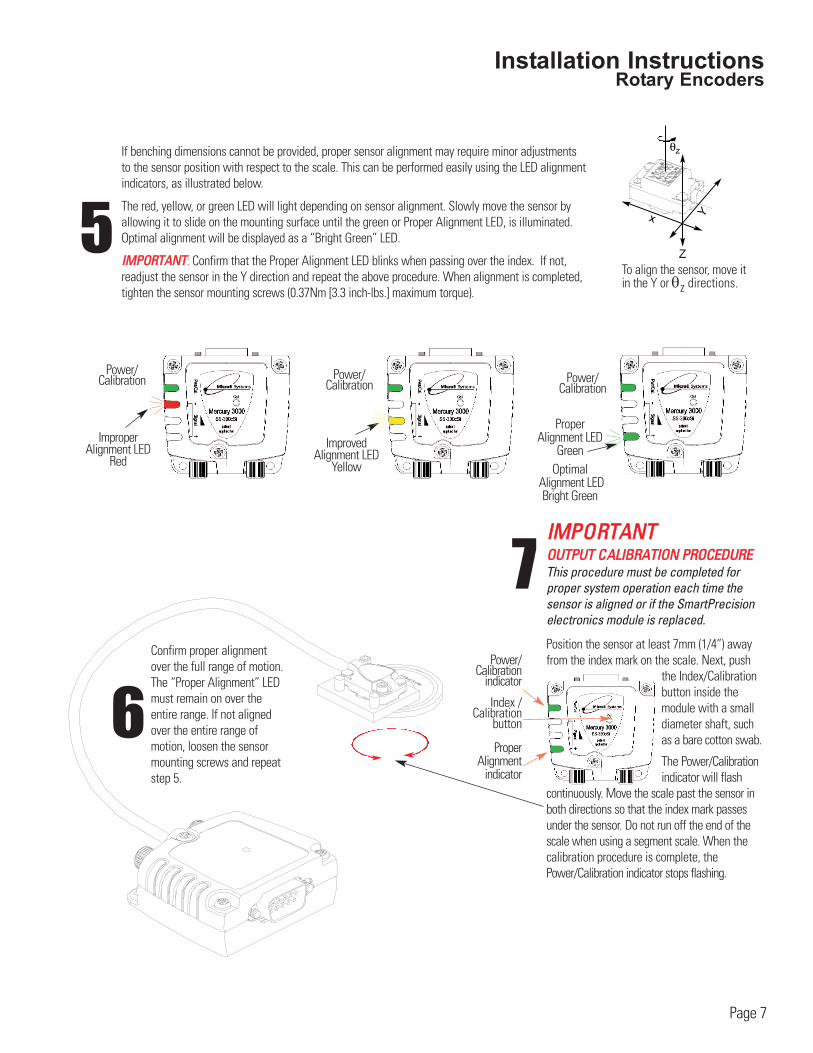
6Confirm proper alignmentover the full range of motion. The “Proper Alignment” LEDmust remain on over theentire range. If not alignedover the entire range ofmotion, loosen the sensormounting screws and repeatstep 5.
5
If benching dimensions cannot be provided, proper sensor alignment may require minor adjustmentsto the sensor position with respect to the scale. This can be performed easily using the LED alignmentindicators, as illustrated below.
The red, yellow, or green LED will light depending on sensor alignment. Slowly move the sensor byallowing it to slide on the mounting surface until the green or Proper Alignment LED, is illuminated.Optimal alignment will be displayed as a “Bright Green” LED.
IIMMPPOORRTTAANNTT: Confirm that the Proper Alignment LED blinks when passing over the index. If not,readjust the sensor in the Y direction and repeat the above procedure. When alignment is completed,tighten the sensor mounting screws (0.37Nm [3.3 inch-lbs.] maximum torque).
x Y
Z
θz
To align the sensor, move itin the Y or θz directions.
IIMMPPOORRTTAANNTTOOUUTTPPUUTT CCAALLIIBBRRAATTIIOONN PPRROOCCEEDDUURREEThis procedure must be completed forproper system operation each time thesensor is aligned or if the SmartPrecisionelectronics module is replaced.
Position the sensor at least 7mm (1/4”) awayfrom the index mark on the scale. Next, push
the Index/Calibration button inside the module with a smalldiameter shaft, suchas a bare cotton swab.
The Power/Calibrationindicator will flash
continuously. Move the scale past the sensor inboth directions so that the index mark passesunder the sensor. Do not run off the end of thescale when using a segment scale. When thecalibration procedure is complete, thePower/Calibration indicator stops flashing.
7Power/
Calibrationindicator
Index /Calibration
button
Proper Alignment
indicator
Improper Alignment LED
Red
Power/Calibration
Power/Calibration Power/
Calibration
ImprovedAlignment LED
Yellow
Proper Alignment LED
GreenOptimal
Alignment LED Bright Green
Reference Section
Installation of Linear Scales
Page 8
MicroE Systems
L0.2L 0.6L 0.2L
Benching pins
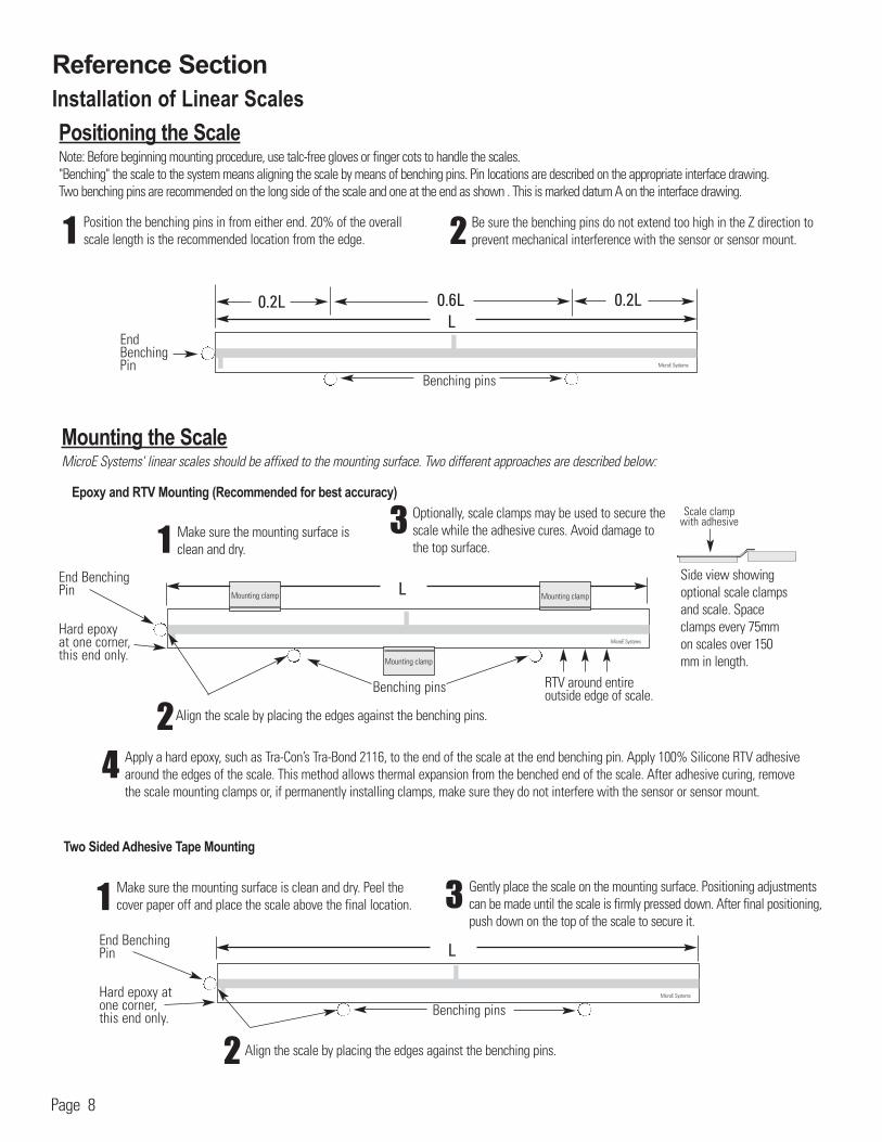
Positioning the ScaleNote: Before beginning mounting procedure, use talc-free gloves or finger cots to handle the scales."Benching" the scale to the system means aligning the scale by means of benching pins. Pin locations are described on the appropriate interface drawing. Two benching pins are recommended on the long side of the scale and one at the end as shown . This is marked datum A on the interface drawing.
Position the benching pins in from either end. 20% of the overallscale length is the recommended location from the edge.
Be sure the benching pins do not extend too high in the Z direction toprevent mechanical interference with the sensor or sensor mount.21
End Benching Pin
Mounting the ScaleMicroE Systems' linear scales should be affixed to the mounting surface. Two different approaches are described below:
RTV around entire outside edge of scale.
End Benching Pin
Hard epoxy at one corner, this end only.
Epoxy and RTV Mounting (Recommended for best accuracy)
1 Make sure the mounting surface isclean and dry.
Optionally, scale clamps may be used to secure thescale while the adhesive cures. Avoid damage tothe top surface.
Side view showingoptional scale clampsand scale. Spaceclamps every 75mmon scales over 150mm in length.
4 Apply a hard epoxy, such as Tra-Con’s Tra-Bond 2116, to the end of the scale at the end benching pin. Apply 100% Silicone RTV adhesivearound the edges of the scale. This method allows thermal expansion from the benched end of the scale. After adhesive curing, removethe scale mounting clamps or, if permanently installing clamps, make sure they do not interfere with the sensor or sensor mount.
3
MicroE Systems
L
2Align the scale by placing the edges against the benching pins.
Benching pins
Scale clampwith adhesive
Mounting clamp
Mounting clamp
Mounting clamp
Benching pinsMicroE Systems
L
2
31
Two Sided Adhesive Tape Mounting
Make sure the mounting surface is clean and dry. Peel the cover paper off and place the scale above the final location.
Align the scale by placing the edges against the benching pins.
Gently place the scale on the mounting surface. Positioning adjustmentscan be made until the scale is firmly pressed down. After final positioning,push down on the top of the scale to secure it.
End Benching Pin
Hard epoxy atone corner, this end only.
Reference Section
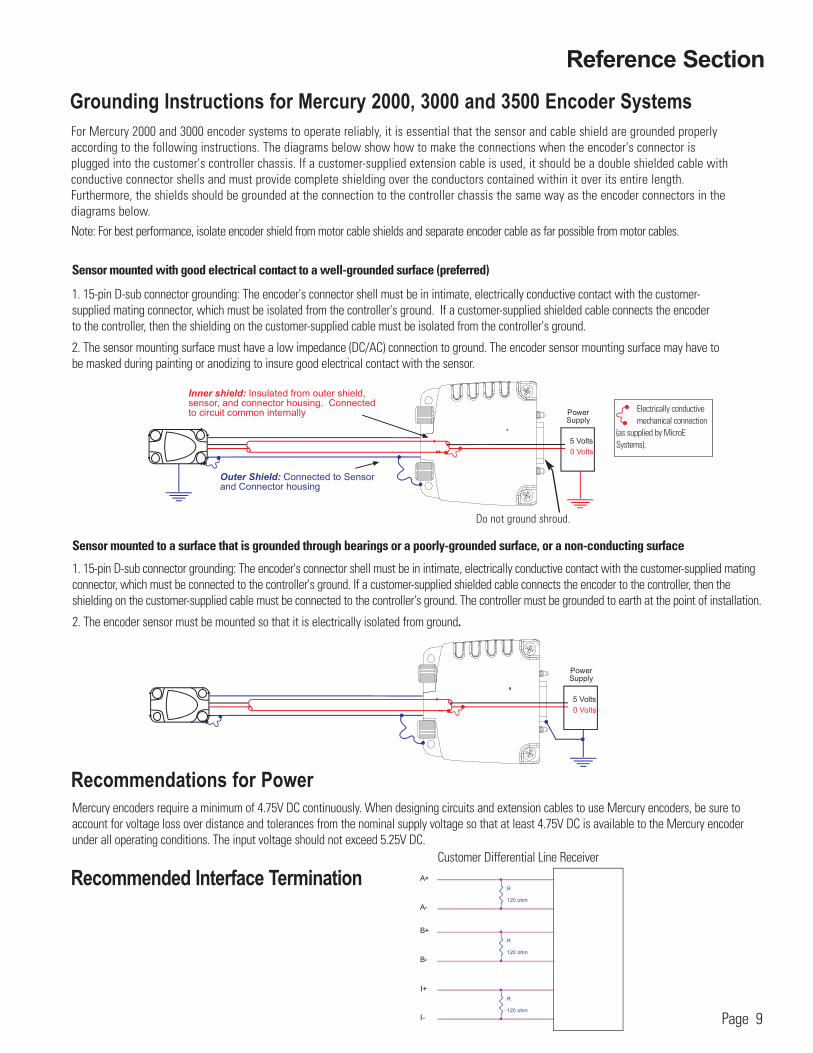
Sensor mounted with good electrical contact to a well-grounded surface (preferred)
1. 15-pin D-sub connector grounding: The encoder's connector shell must be in intimate, electrically conductive contact with the customer-supplied mating connector, which must be isolated from the controller's ground. If a customer-supplied shielded cable connects the encoder to the controller, then the shielding on the customer-supplied cable must be isolated from the controller's ground.
2. The sensor mounting surface must have a low impedance (DC/AC) connection to ground. The encoder sensor mounting surface may have to be masked during painting or anodizing to insure good electrical contact with the sensor.
For Mercury 2000 and 3000 encoder systems to operate reliably, it is essential that the sensor and cable shield are grounded properlyaccording to the following instructions. The diagrams below show how to make the connections when the encoder's connector isplugged into the customer's controller chassis. If a customer-supplied extension cable is used, it should be a double shielded cable withconductive connector shells and must provide complete shielding over the conductors contained within it over its entire length.Furthermore, the shields should be grounded at the connection to the controller chassis the same way as the encoder connectors in thediagrams below.Note: For best performance, isolate encoder shield from motor cable shields and separate encoder cable as far possible from motor cables.
Sensor mounted to a surface that is grounded through bearings or a poorly-grounded surface, or a non-conducting surface
1. 15-pin D-sub connector grounding: The encoder's connector shell must be in intimate, electrically conductive contact with the customer-supplied matingconnector, which must be connected to the controller's ground. If a customer-supplied shielded cable connects the encoder to the controller, then the shielding on the customer-supplied cable must be connected to the controller's ground. The controller must be grounded to earth at the point of installation.
2. The encoder sensor must be mounted so that it is electrically isolated from ground.
Mercury encoders require a minimum of 4.75V DC continuously. When designing circuits and extension cables to use Mercury encoders, be sure toaccount for voltage loss over distance and tolerances from the nominal supply voltage so that at least 4.75V DC is available to the Mercury encoderunder all operating conditions. The input voltage should not exceed 5.25V DC.
Outer Shield: Connected to Sensorand Connector housing
5 Volts
0 Volts
PowerSupply
Grounding Instructions for Mercury 2000, 3000 and 3500 Encoder Systems
Recommendations for Power
Page 9
Customer Differential Line Receiver
Recommended Interface Termination
B-
IW-
R
120 ohm
B+
A+
R
120 ohm
R
120 ohm
IW+
A-
I+
I-
Outer Shield: Connected to Sensorand Connector housing
Inner shield: Insulated from outer shield,sensor, and connector housing. Connectedto circuit common internally (pin 4).
5 Volts
0 Volts
PowerSupply
Electrically conductivemechanical connection
(as supplied by MicroESystems).
Do not ground shroud.
Reference Section
Page 10
Mercury 3500, 3000, 2000
Signal Twisted PairA+ Pair 1A-B+ Pair 2B-
Index+ Pair 3Index-+5V Pair 4
GND
Customer Interface Cable RequirementsCustomer cables that interface to Mercury series encoders must have the following characteristics:• Twisted pair signal wiring.• Characteristic impedance of 100-120 ohms.• Sufficient wire gauge to meet the minimum voltage requirement at the encoder, for example 24AWG gauge wire for a 2m length cable.
Examples of acceptable cables with 24 AWG gauge wire and 4 twisted pairs are Belden 9831, 8104, and 9844 or other manufacturer's equivalents.
• Single shield cable with a minimum of 90% coverage. Note that a double shielded cable may be required in high-noise applications.
Signal Wiring:Each differential signal should be connected to a corresponding twisted pair as follows:
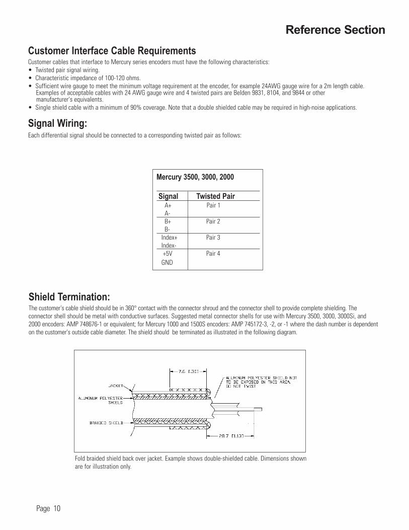
Shield Termination:The customer's cable shield should be in 360° contact with the connector shroud and the connector shell to provide complete shielding. The connector shell should be metal with conductive surfaces. Suggested metal connector shells for use with Mercury 3500, 3000, 3000Si, and 2000 encoders: AMP 748676-1 or equivalent; for Mercury 1000 and 1500S encoders: AMP 745172-3, -2, or -1 where the dash number is dependenton the customer's outside cable diameter. The shield should be terminated as illustrated in the following diagram.
Fold braided shield back over jacket. Example shows double-shielded cable. Dimensions shownare for illustration only.

Page 11
SmartPrecisionTM Module Mounting Options
Declaration of CE Conformance
The SmartPrecisionTM electronincs module may be mounted directly to a bulkhead connector using the integral thumb screws shown in figure A.
Alternatively, the module may be used with an extension cable and mounted to a base plate using the mounting tabs as shown in figure B.
A B
Reference Section

Troubleshooting
ProblemThe Power/Calibration indicator will not come on.
Solution• Make sure that the SmartPrecisionTM electronics’ 15-pin D-sub connector is fully seated and connected.• Confirm that +5 Volts DC is being applied to pin 12 on the SmartPrecisionTM electronics’ 15-pin HD connector and that pin 13 is connected toground.
ProblemCan't get the SmartPrecision TTMM electronics’ "Signal" LEDs better than red or yellow; or the green, “ Proper Alignment” indicator doesn't stay illuminated over the full length of the scale.
Solution• Verify that the sensor has been aligned to the scale and that the mounting screws are tight. Check the dimensions for the mechanical
mounting holes (and clamps if any) to make sure that the sensor is correctly located over the scale. Refer to appropriate the interface drawing.
• Check that the scale is firmly mounted and can't jiggle or move in other than the intended direction.• Make sure that the scale is clean over its entire length or circumference.
ProblemThe green Power/Calibration indicator is flashing unexpectedly.
Solution• Part of the normal setup procedure is to activate the SmartPrecisionTM electronics’ Index/Calibration process by pressing the recessed
button the SmartPrecisionTM electronics’ connector body. The On/Index LED will begin to flash until the index mark on the scale passes under the sensor at least one time in each direction.
ProblemCan't Complete the Index/Calibration process - the green Power/Calibration indicator doesn't stop flashing.
Solution• Verify that the sensor is mounted in the correct orientation to the scale for the desired index mark. Refer to the interface drawing.• Refer to step 5 of the installation procedure to insure proper operation.
Cleaning scales General ParticleRemovalBlow off the contamination withnitrogen, clean air,or a similar gas.
Page 12
ContaminationRemovalUse a lint-free clean-room wipe or cottonswab dampened withisopropyl alcohol oracetone only to wipethe surface clean.Handle the scale by theedges. Do not scrub the scale.

World Headquarters: 125 Middlesex Turnpike • Bedford • MA 01730 USAwww.microesys.com • [email protected] • T. [781] 266-5700 • F. [781] 266-5112
© 2008 MicroE Systems
Thank you for purchasing a MicroE Systems product. You should expect the highest level of quality and support from MicroE. If you want to download the Mercury Encoder Installation Manual, Data Sheet orInterface Drawing, browse www.microesys.com and click on the Mercury Encoders button.
Contacting MicroE Systems