mep filling machine - stpats.com manuals/rv25nglese2.pdf · page mep filling machine addendum:...
TRANSCRIPT
page �
MEP Filling Machine Addendum: Setup and Maintenance
Read this addendum and the MEP manual carefully before operating the filler.One person should be assigned to maintain the filler. Only this primary operator should make adjustments. This primary operator should train additinal operators. However, adjust-ments should be made by, or under the careful supervision of the primary operator.
••
This manual and parts are available online.
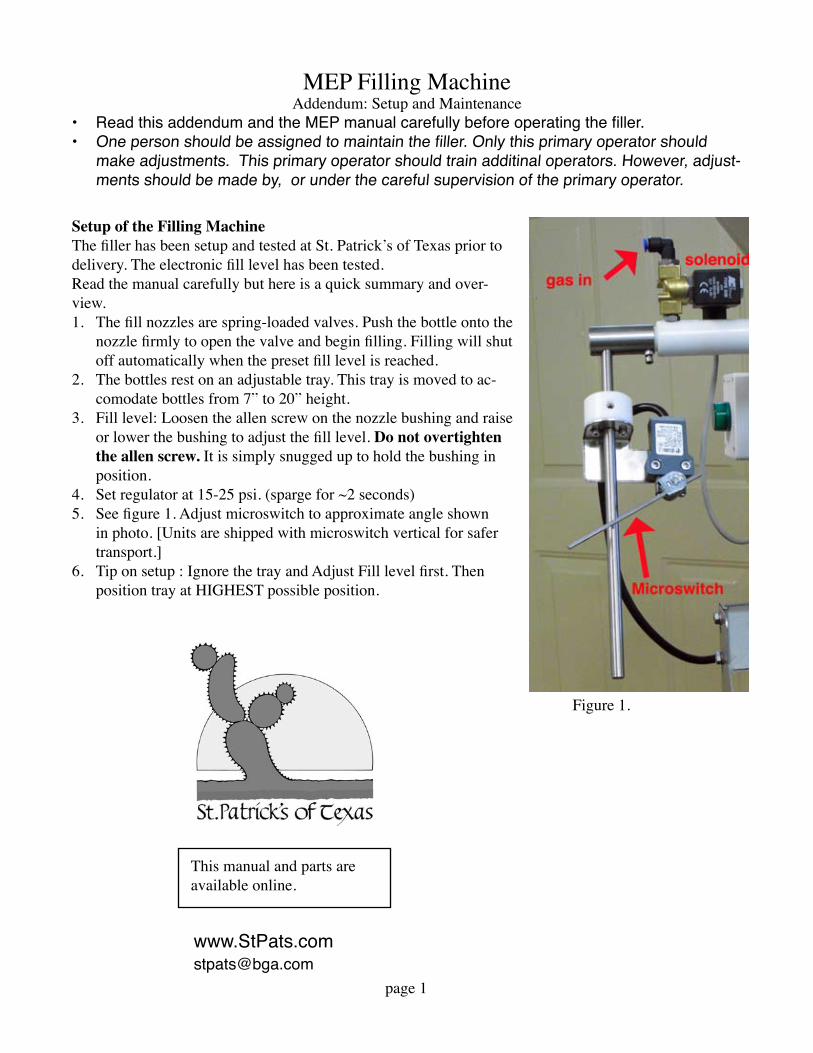
Setup of the Filling MachineThe filler has been setup and tested at St. Patrick’s of Texas prior to delivery. The electronic fill level has been tested. Read the manual carefully but here is a quick summary and over-view.
The fill nozzles are spring-loaded valves. Push the bottle onto the nozzle firmly to open the valve and begin filling. Filling will shut off automatically when the preset fill level is reached.The bottles rest on an adjustable tray. This tray is moved to ac-comodate bottles from 7” to 20” height.Fill level: Loosen the allen screw on the nozzle bushing and raise or lower the bushing to adjust the fill level. Do not overtighten the allen screw. It is simply snugged up to hold the bushing in position.Set regulator at 15-25 psi. (sparge for ~2 seconds)See figure 1. Adjust microswitch to approximate angle shown in photo. [Units are shipped with microswitch vertical for safer transport.]Tip on setup : Ignore the tray and Adjust Fill level first. Then position tray at HIGHEST possible position.
�.
2.
3.
4.5.
6.
Figure �.

page 2
Periodic MaintenanceKeep filler clean and dry. Do not store in humid or wet area. Nozzles should be lubricated routinely. Food grade silicone spray is fine for daily use---simply spray on moving parts.If nozzles are disassembled for cleaning, use a heavy food grade grease before reassembling. Drain tank well after use. Do not use corrosive chemicals.Drain pumphead after use. Do not use corrosive chemicals.
DO NOTDO NOT use OZONE to clean a filler. Ozone will destroy all rubber and plastic components and should NEVER be used on equipment with rubber or plastic components.DO NOT use a HOSE or PRESSURE WASHER to clean a filling machine. Simply wipe down with clean damp cloth. Pressure washers should NEVER be used on equipment with bearings or electrical components. DO NOT use METABISULFITE (or any harsh chemicals) for cleaning or sanitizing. Metabisulfite is not a sanitizer nor a cleaner and should NEVER be used as such. Metabisulfite is corrosive to most metals including stainless steel.
�.2.
3.4.5.
�.
2.
3.
Sensitivity of Electronic level control. This is located inside electrical box. Sensitivity=2.5 kOhm, Mode=UP, Delay=OffThis is least sensitive setting and is good for wine. Products that have distilled water (some vodkas for example), may need increased sensitivity. Just try the unit first---if pump is not turning on/off as it should---increase the sensitivity.
See Fig. 2. Do NOT overtighten the small bolt that holds nozzle to the tee. The nozzle must be able to rotate freely. Overtightening of this bolt will result in the nozzle tube being snapped off at the tee.
See Fig. 2. Do NOT overtighten the set screw on the ring that holds the rubber cone.
See Fig. 3. Clean and lubricate solenoid valve annually (or if it will not open). See Fig. 1 and Fig. 3. Remove black electrical component. Then remove stainless stem. Clean rubber tip, inside housing, and use light lubricant and reassemble.
Note: If solenoid valve ‘sputters’, reduce the pressure. 25 psi is a typical maximum pressure that the valve can operate, but precise max pressure this depends on line voltage, cleanliness and lubrication of the valve, ...
Figure 2. Do NOT overtighen these bolts.
Fig. 3. Cleaning sole-noid valve.
M.E.P. - operator's handbook - Rv25 filling machine
1
CONDITIONS OF SALE AND WARRANTY
1. Read carefully this operator's handbook before operating our Rv25 filling machine.
2. M.E.P. guarantees this Rv25 filling machine in case of breakages caused by faulty
components or incorrect assembly.
3. The Rv25 filling machine has a 12-month guarantee. 12 month period begins on
shipping date from St. Patrick’s of Texas. This guarantee is valid only for the first
owner of the filling machine.
4. Warranty only consists in replacing the damaged parts and it does include neither
refunds for losses caused by the shutdown of the machine nor any cost of labour or
any transport cost to send the filling machine to a repair shop.
5. Any repair or modification made to the machine by unauthorized personnel will make
the warranty void.
6. We cannot be held responsible for damages due to incorrect use of the filling
machine, or failure to carry out maintenance and lubrication, or problems or damage
incurred during transport.
7. M.E.P. reserves the right to introduce changes without previous notice to the Rv25
filling machine; however, the supply of spare parts of the previous models will be
guaranteed.
INDEX
1 .............................. Description of the Rv25 filling machine
2 .............................. Technical details
3 .............................. Operating directions
4 .............................. Maintenance
5 .............................. Faults and remedies check list

M.E.P. - operator's handbook - Rv25 filling machine
2
1. DESCRIPTION OF THE Rv25 FILLING MACHINE
Our Rv25 filling machine can be used to bottle wine or other food products as long as
they are not too thick.
This filling machine is almost entirely made of stainless steel; there are some parts made
of synthetic materials (such as delrin and silicone rubber) which do not react either with
the air or food products.
Safety symbols:
General danger
Caution: refer to the operator's handbook
Caution: 230 Volt tension (or 110 Volt)
M.E.P. - operator's handbook - Rv25 filling machine
3
2. TECHNICAL DETAILS
This four-spout filling machine operates on falling principle; the four spouts have a conic
seal and a 14 mm diameter.
This filling machine can be used with bottles up to 400 mm high, made of glass or
undeformable material (deformable plastic bottles can't be used).
The inside diameter of the neck of the bottle must be between 15 and 28 mm.
Rv25 filling machine equipped with wheeled support
height: 1550 mm
width: 600 mm
length: 550 mm
weight: 40 kg

M.E.P. - operator's handbook - Rv25 filling machine
4
3. OPERATING DIRECTIONS
Positioning. Place the Rv25 filling machine on a steady support in a lit up room. In case
the filling machine is fitted up with a wheeled support, make sure it is placed on an even
ground and put on the brakes to the two front wheels.
Picture 1.
First attach the hose to the hose barb of the inlet- (see picture 1) and secure it with a
clamp. Check that the outlet valve is closed (see picture 1).
M.E.P. - operator's handbook - Rv25 filling machine
5
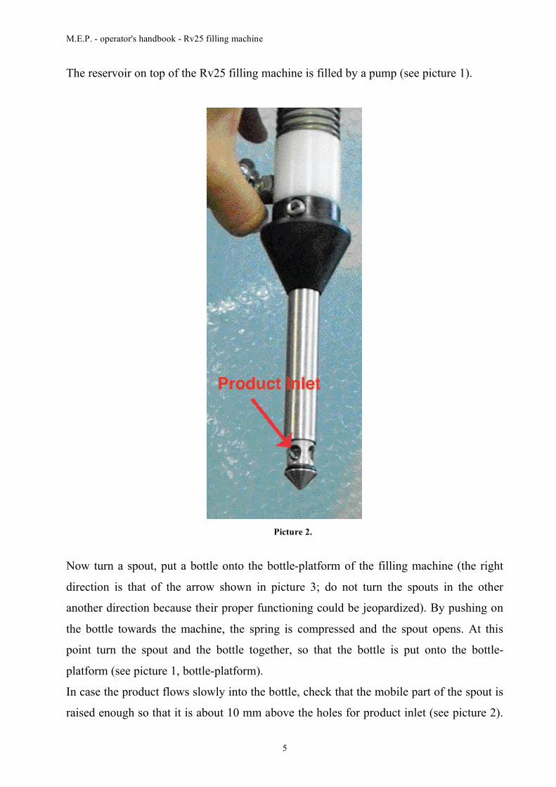
The reservoir on top of the Rv25 filling machine is filled by a pump (see picture 1).
Picture 2.
Now turn a spout, put a bottle onto the bottle-platform of the filling machine (the right
direction is that of the arrow shown in picture 3; do not turn the spouts in the other
another direction because their proper functioning could be jeopardized). By pushing on
the bottle towards the machine, the spring is compressed and the spout opens. At this
point turn the spout and the bottle together, so that the bottle is put onto the bottle-
platform (see picture 1, bottle-platform).
In case the product flows slowly into the bottle, check that the mobile part of the spout is
raised enough so that it is about 10 mm above the holes for product inlet (see picture 2).

M.E.P. - operator's handbook - Rv25 filling machine
6
If it is not, the position of the bottle-platform must be changed. To do that, loosen the two
fastening knobs of the bottle-platform by unscrewing them almost entirely (see picture 3,
fastening knobs of the bottle-platform) and turn the bottle-platform so as to disconnect
the fastening rod (see picture 1); then relocate it higher. Be careful and keep the bottle-
platform in the horizontal position. Do not set the bottle-platform too high because the
bottle must rest on the bottle platform while compressing the upper spring of the spout.
The machine has a back support to which the bottles on the bottle-platform must be leant
against. The position of this support can be adjusted by unscrewing the two bolts.
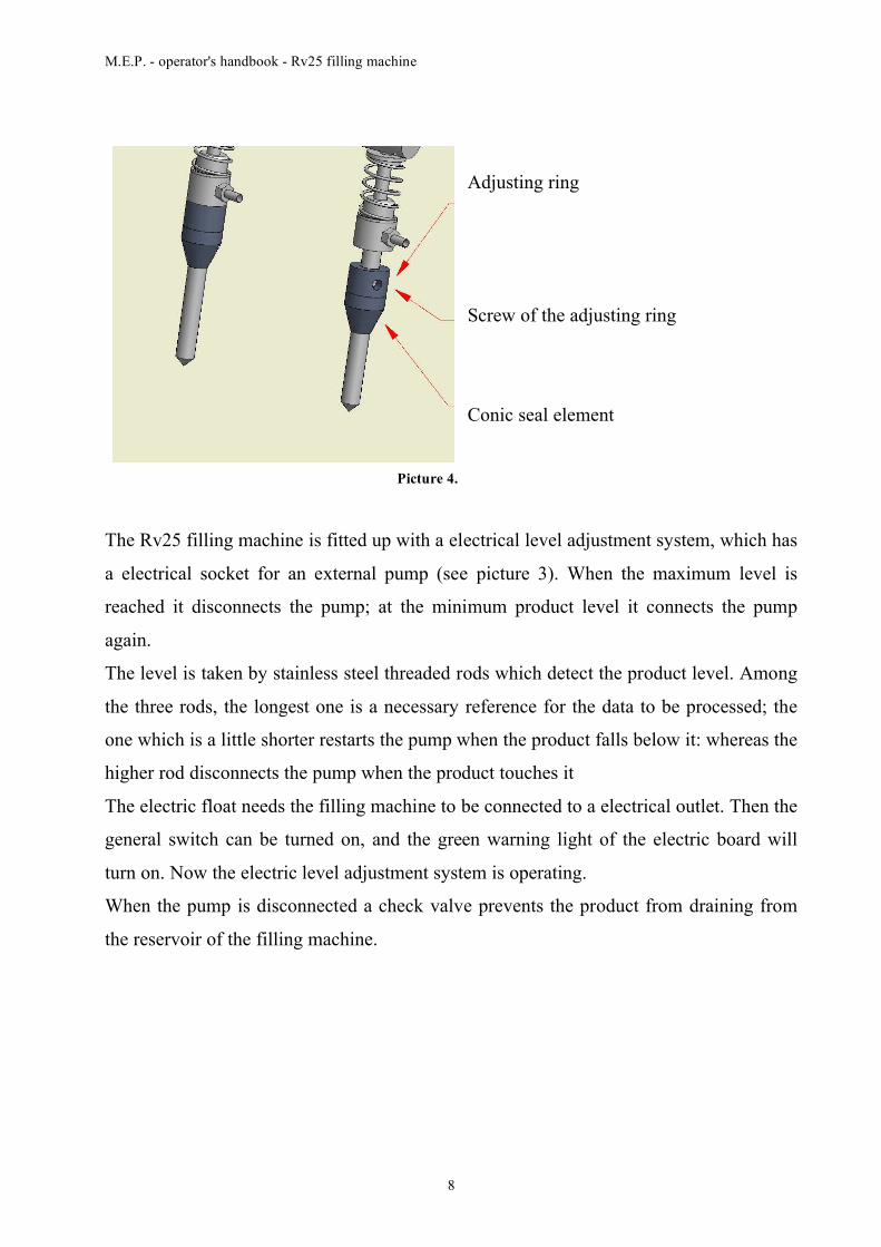
To adjust the level of product inside the bottles, you must unthread the set screw of the
adjusting rings of the spouts using a hexagonal (allen) wrench and lower both the ring
and the rubber conical seal (see picture 4). Once you have obtained the level wanted,
make the same adjustment to all the spouts and tighten the screws, but be careful not to
tighten them too much.
In case the level must be adjusted a good deal, it might be necessary to lower the bottle-
platform.
M.E.P. - operator's handbook - Rv25 filling machine
7
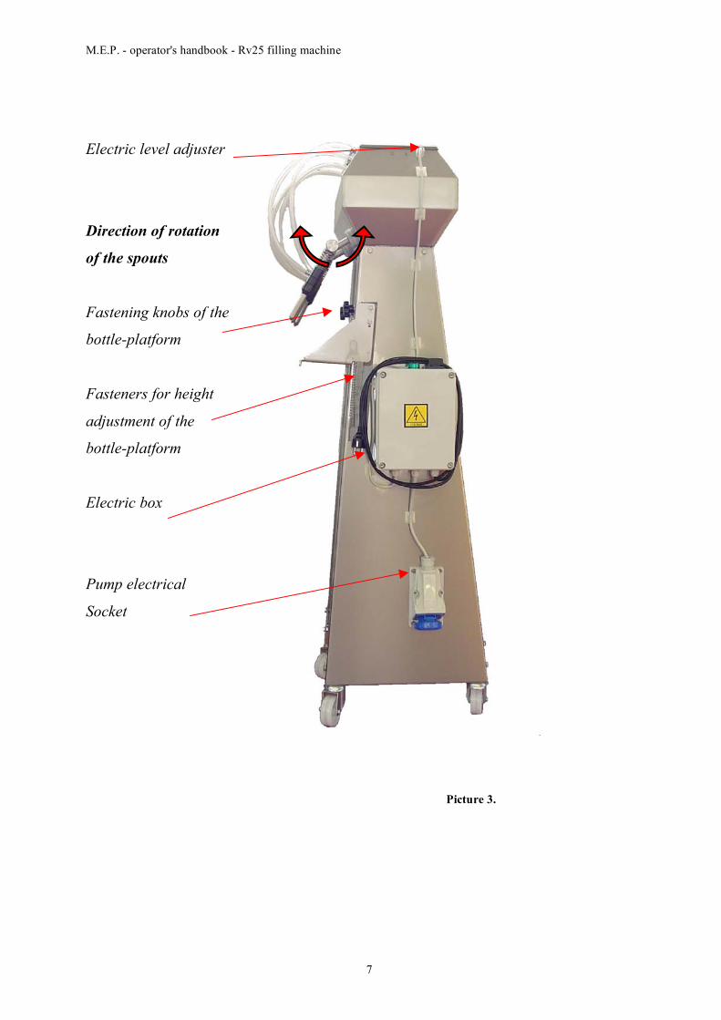
Electric level adjuster
Direction of rotation
of the spouts
Fastening knobs of the
bottle-platform
Fasteners for height
adjustment of the
bottle-platform
Electric box
Pump electrical
Socket
Picture 3.
M.E.P. - operator's handbook - Rv25 filling machine
8
Adjusting ring
Screw of the adjusting ring
Conic seal element
Picture 4.
The Rv25 filling machine is fitted up with a electrical level adjustment system, which has
a electrical socket for an external pump (see picture 3). When the maximum level is
reached it disconnects the pump; at the minimum product level it connects the pump
again.
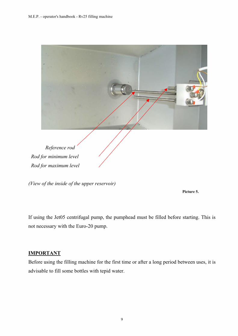
The level is taken by stainless steel threaded rods which detect the product level. Among
the three rods, the longest one is a necessary reference for the data to be processed; the
one which is a little shorter restarts the pump when the product falls below it: whereas the
higher rod disconnects the pump when the product touches it
The electric float needs the filling machine to be connected to a electrical outlet. Then the
general switch can be turned on, and the green warning light of the electric board will
turn on. Now the electric level adjustment system is operating.
When the pump is disconnected a check valve prevents the product from draining from
the reservoir of the filling machine.
M.E.P. - operator's handbook - Rv25 filling machine
9
Reference rod
Rod for minimum level
Rod for maximum level
(View of the inside of the upper reservoir) Picture 5.
If using the Jet05 centrifugal pump, the pumphead must be filled before starting. This is
not necessary with the Euro-20 pump.
IMPORTANT
Before using the filling machine for the first time or after a long period between uses, it is
advisable to fill some bottles with tepid water.
M.E.P. - operator's handbook - Rv25 filling machine
10
4. MAINTENANCE
At the end of work, open the outlet valve and empty the reservoir.
Then it is advisable to fill some bottles with tepid water to remove the residual products
and guarantee a longer life of the gaskets.
For more accurate maintenance, disassemble each spout by unscrewing the lower seal
(see element no. 1, picture 6); now, their inner parts can be cleaned. Use heavy weight
food grade grease and reassemble.
Flush unit with clean water at the end of each use. Remove pump hoses and drain.
M.E.P. - operator's handbook - Rv25 filling machine
11
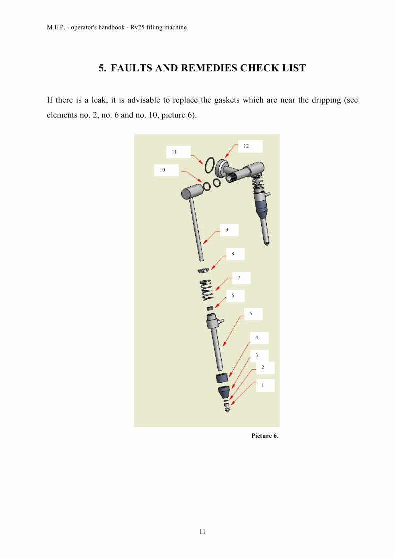
5. FAULTS AND REMEDIES CHECK LIST
If there is a leak, it is advisable to replace the gaskets which are near the dripping (see
elements no. 2, no. 6 and no. 10, picture 6).
Picture 6.
1
2
3
4
5
6
7
8
9
10
11 12
M.E.P. - operator's handbook - Rv25 filling machine
12
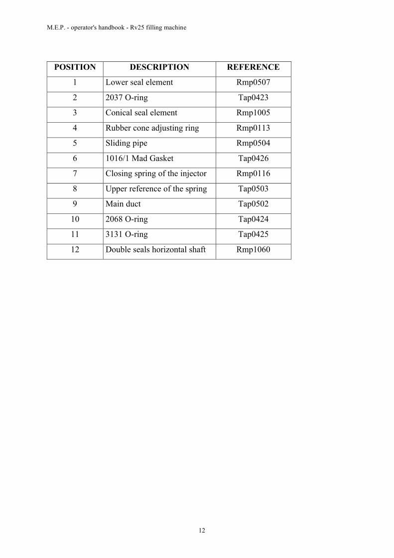
POSITION DESCRIPTION REFERENCE
1 Lower seal element Rmp0507
2 2037 O-ring Tap0423
3 Conical seal element Rmp1005
4 Rubber cone adjusting ring Rmp0113
5 Sliding pipe Rmp0504
6 1016/1 Mad Gasket Tap0426
7 Closing spring of the injector Rmp0116
8 Upper reference of the spring Tap0503
9 Main duct Tap0502
10 2068 O-ring Tap0424
11 3131 O-ring Tap0425
12 Double seals horizontal shaft Rmp1060
M.E.P. - operator's handbook - Rv25 filling machine
13
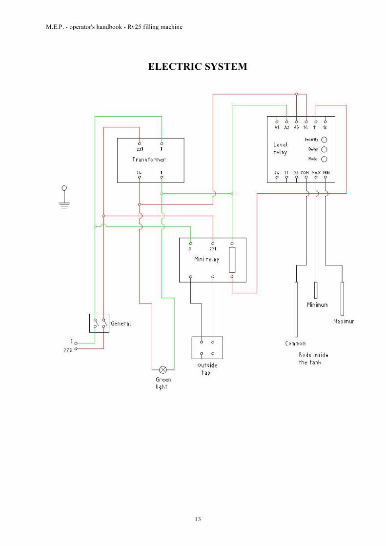
ELECTRIC SYSTEM