mep 807a 100 kw dvr and gsc programing ... to verify the dvr parameter settings use the following...
TRANSCRIPT

MEP 807A 100 KW
DVR AND GSC PROGRAMING
FAULTS
AND
ALARM CODES

2
3
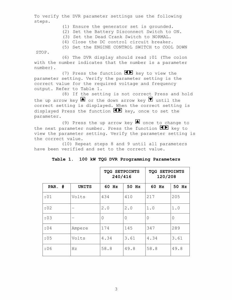
To verify the DVR parameter settings use the following
steps.
(1) Ensure the generator set is grounded.
(2) Set the Battery Disconnect Switch to ON.
(3) Set the Dead Crank Switch to NORMAL.
(4) Close the DC control circuit breaker.
(5) Set the ENGINE CONTROL SWITCH to COOL DOWN
STOP.
(6) The DVR display should read :01 (The colon
with the number indicates that the number is a parameter
number).
(7) Press the function key to view the
parameter setting. Verify the parameter setting is the
correct value for the required voltage and frequency
output. Refer to Table 1.
(8) If the setting is not correct Press and hold
the up arrow key or the down arrow key until the
correct setting is displayed. When the correct setting is
displayed Press the function key, once to set the
parameter.
(9) Press the up arrow key once to change to
the next parameter number. Press the function key to
view the parameter setting. Verify the parameter setting is
the correct value.
(10) Repeat steps 8 and 9 until all parameters
have been verified and set to the correct value.
Table 1. 100 kW TQG DVR Programming Parameters
TQG SETPOINTS
240/416
240/416
TQG SETPOINTS
120/208
120/208
PAR. # UNITS 60 Hz 50 Hz 60 Hz 50 Hz
:01 Volts 434 410 217 205
:02 – 2.0 2.0 1.0 1.0
:03 – 0 0 0 0
:04 Ampere 174 145 347 289
:05 Volts 4.34 3.61 4.34 3.61
:06 Hz 58.8 49.8 58.8 49.8

4
Table 1. 100 kW TQG DVR Programming Parameters (Cont)
TQG SETPOINTS
240/416
TQG SETPOINTS
120/208
PAR. # UNITS 60 Hz 50 Hz 60 Hz 50 Hz
:07 Volts/Hz 3.0 3.0 3.0 3.0
:08 Volts/Hz 2.0 2.0 2.0 2.0
:09 % 50.0 50.0 50.0 50.0
:10 Hz 25.0 25.0 25.0 25.0
:11 % 125.0 125.0 125.0 125.0
:12 Seconds 2 2 2 2
:13 % 75 75 75 75
:14 Seconds 30 30 30 30
:15 % 0 0 0 0
:16 – 2.4 2.4 2.4 2.4
:17 – 1.0 1.0 1.0 1.0
:18 – 0000 0000 0000 0000
:19 Ampere 2.0 2.0 2.0 2.0
:20 Seconds .5 .5 .5 .5
:21 – 2 2 2 2
:22 – 0 0 0 0
:30 % 1.8 1.8 1.8 1.8
:34 % 20 20 20 20
:35 Seconds 7 7 7 7

5
Table 1. 100 kW TQG DVR Programming Parameters (Cont)
TQG SETPOINTS
240/416
TQG SETPOINTS
120/208
PAR. # UNITS 60 Hz 50 Hz 60 Hz 50 Hz
:50 Frequency View
:51 Voltage View
:52 Current View
:53 Reactive
output
Current
View
:54 Gen. Real
Current
View
:55 Exciter
field
Current
View
:56 3-phase
KW
View
:57 Power
Factor
View
:58 3-phase
kVAR
View
:60 Hours View
:90 –
:91 – 1.05 1.05 1.05 1.05
:92 Latest
Fault
View
:93 Previous
Fault
View
:94 Fault
Clear
Switch
:96 Shutdown
Fault
Reset
Switch

6
1. Parameters 50 – 60 are viewable values such as frequency and voltage and hours of operation on the
DVR.
The GSC Parameter settings are programmed in separate
Operational Parameters. Refer to the Tables listed below:
Table 2 - OP5-0 Engine/Generator Set point Programming
Table 3 - OP5-1 Protective Relaying Set point Programming
Table 4 - OP5-3 Synchronization Set point Programming
Table 5 - OP6-0 Spare Input/Output Set point Programming
Table 6 - OP8 data from ATB and BTB transformers
To verify the GSC parameter settings use the following
steps.
1. Set Battery Disconnect Switch to ON.
2. Set DEAD CRANK SWITCH to NORMAL.
3. On EMCP, set ENGINE CONTROL switch to COOL DOWN/STOP.
4. Press SERVICE MODE key on GSC. SERV will be displayed on
upper display. OP1 will be displayed on lower display.
*NOTE: In SERVICE MODE, the buttons on the GSC keypad
perform new functions as follows:
POWER METER is Scroll Right, key 1
AC METER is Scroll Up, key 2
ENGINE METER is Scroll Down, key 3
LAMP TEST is Select
ALARM CODES is Enter
5. Press AC METER key five times. OP3 will be displayed.
6. Press the LAMP TEST key. P E ----- will be displayed.
7. Press POWER METER key. P E 1---- will be displayed.
8. Press ENGINE METER key. P E 1 3--- will be displayed.
9. Press AC METER key. P E 1 3 2 -- will be displayed.
10. Press ENGINE METER key. P E 1 3 2 3 - will be
displayed.
11. Press POWER METER key. P E 1 3 2 3 1 will be displayed.
12. Press ALARM CODES key. P E PASS will be displayed.
13. Press EXIT key. OP4 will be displayed.
14. Scroll up or down to the required parameter.(OP5-0 is
the first parameter to be verified)
15. Press the Lamp Test key, the first parameter setting
will display. If the setting is not correct press the lamp
test key the setting will begin to flash. Scroll up or down
until the correct setting is displayed. Press the Alarm
Codes Key the value will be entered and stop flashing.
Scroll up to the next setting.
16. Verify all parameters in the appropriate table.
7
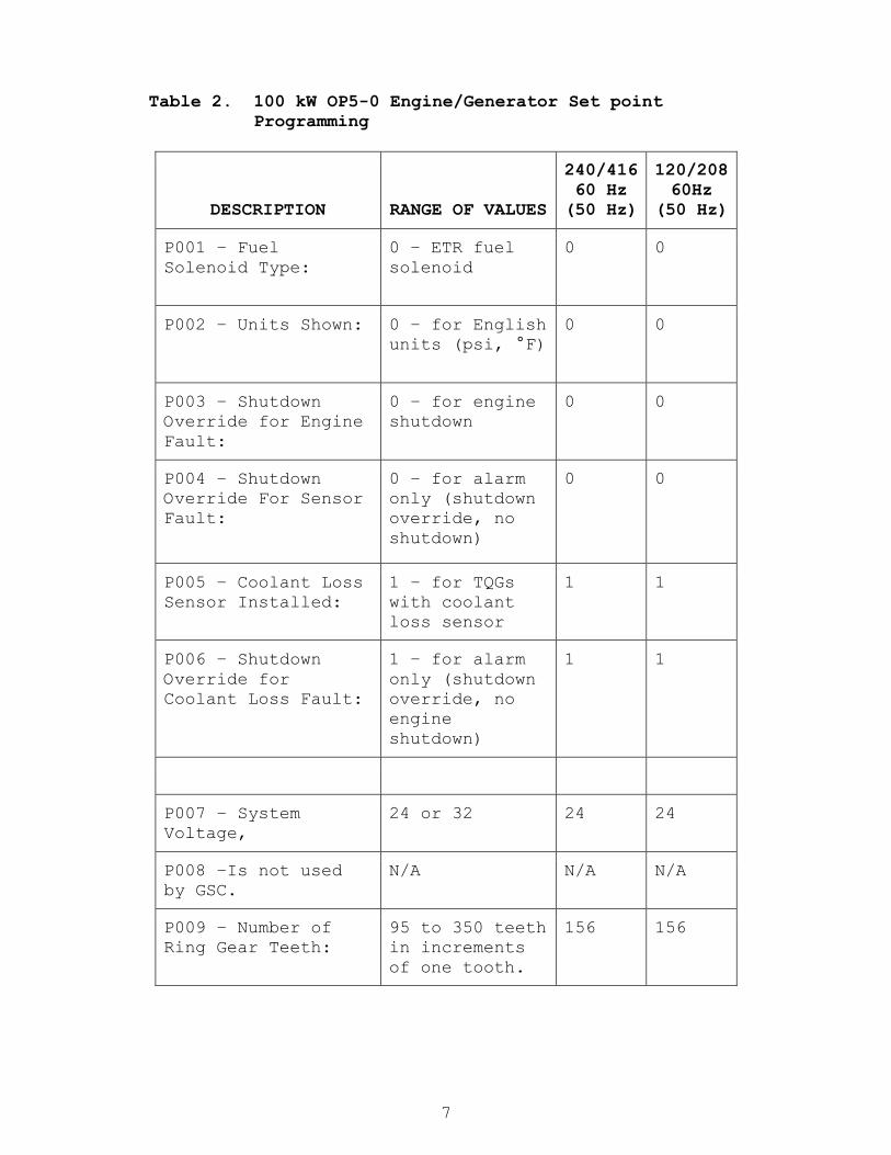
Table 2. 100 kW OP5-0 Engine/Generator Set point
Programming
DESCRIPTION RANGE OF VALUES
240/416
60 Hz
(50 Hz)
120/208
60Hz
(50 Hz)
P001 – Fuel
Solenoid Type:
0 – ETR fuel
solenoid
0 0
P002 – Units Shown: 0 – for English
units (psi, °F)
0 0
P003 – Shutdown
Override for Engine
Fault:
0 – for engine
shutdown
0 0
P004 – Shutdown
Override For Sensor
Fault:
0 – for alarm
only (shutdown
override, no
shutdown)
0 0
P005 – Coolant Loss
Sensor Installed:
1 – for TQGs
with coolant
loss sensor
1 1
P006 – Shutdown
Override for
Coolant Loss Fault:
1 – for alarm
only (shutdown
override, no
engine
shutdown)
1 1
P007 – System
Voltage,
24 or 32 24 24
P008 –Is not used
by GSC.
N/A N/A N/A
P009 – Number of
Ring Gear Teeth:
95 to 350 teeth
in increments
of one tooth.
156 156

8
Table 2. 100 kW OP5-0 Engine/Generator Set point
Programming (Cont)
DESCRIPTION RANGE OF VALUES
240/416
60 Hz
(50 Hz)
120/208
60Hz
(50 Hz)
P010 – Engine Over
speed:
500 to 4330 rpm
in increments
of 10 rpm.
2120
rpm
2120
rpm
P011 – Crank
Terminate Speed:
100 to 1000 rpm
10 rpm.
400 rpm 400 rpm
P012 – Oil Step
Speed:
400 to 1800 rpm 1350
rpm
1350
rpm
P013 – Low Oil
Pressure Shutdown
at Rated Speed: 2
34 to 420 kPa
(5 to 61 psi)
26 psi 26 psi
P014 – Low Oil
Pressure Shutdown
at Idle Speed: 2
20 to 336 kPa
(3 to 49 psi)
10 psi 10 psi
P015 – High Water
Temperature
Shutdown: 3
85 to 123°C
(185 to 253°F)
230°F 230°F
P016 – Low Water
Temperature Alarm:
0 to 36°C (32
to 97°F)
70°F 70°F
P017 – Total Cycle
Crank Time:
5 to 120
seconds
90 sec 90 sec
P018 – Cycle Crank
Time:
5 to 60 seconds 30 sec 30 sec
P019 – Cooldown
Time:
0 to 30 minutes 5 min 5 min
P020 – AC Voltage: 700 700 700
P021 – AC Current
Full Scale:
75, 100, 150,
200, 300, 400
400 400
P022 – GSC Engine
Number:
01 through 08 01 01
P023 – Engine Type: 2 – EUI diesel 2 2

9
2 When oil pressure drops to within 34 kappa (5 psi) of the
P013 or P014 set point, GSC issues a low oil pressure
alarm.
3 When coolant temperature rises to within 6°C (11°F) of the
P015 set point, GSC issues high coolant temperature alarm.
Table 2. 100 kW OP5-0 Engine/Generator Set point
Programming (Cont)
DESCRIPTION RANGE OF VALUES
240/416
60 Hz
(50 Hz)
120/208
60Hz
(50 Hz)
P024 – Crank Time
Delay:
0 to 20 seconds 5 sec 5 sec
P025 – Oil
Temperature Sensor
Installed:
0 – for TQGs
without an oil
temperature
sensor
0 0
P026 – High Oil
Temperature
Shutdown:
185 to 253°F 253°F 253°F
P027 –High Oil
Temperature Fault:
0 – (no engine
shutdown)
0 0
P028 – Nameplate
Voltage:
100 to 25kV in
increments of 1
416V
(416V)
208V
(208V)
P029 – Nameplate
Current:
0 to 4000 A in
increments of 1
173A
(144A)
347A
(288A)
P030 – Nameplate
Power:
0 through 10 MW 100 kW
(83
kW)
100 kW
(83
kW)
P031 – Rated
Frequency:
50 or 60 Hz 60 Hz
(50
Hz)
60 Hz
(50
Hz)
P032 – Connection
Configuration of
Generator:
0 – Wye
1 – Delta
0 0
P033 – Number of
Generator Poles.
0 through 254 4 4

10
Table 3. OP5-1 Protective Relaying Set point Programming
DESCRIPTION RANGE OF VALUES
SETPOINTS
60 Hz (50
Hz)
P101 Generator Over
voltage Alarm Enable:
1 – enabled 1
P102 – Generator Over
voltage Alarm Threshold:
100 to 125% of
nameplate voltage
125%
P103 – Generator Over
voltage Alarm Time Delay:
0 through 120
seconds 2
0
P104 – Generator Over
voltage Shutdown Enable:
1 – enabled 1
P105 – Generator Over
voltage Shutdown
Threshold:
100 to 125% of
nameplate voltage
125%
P106 – Generator Over
voltage Shutdown Time
Delay:
0 through 120
seconds
1 sec
P107 – Generator Under
voltage Alarm Enable:
1 – enabled 1
P108 – Generator Under
voltage Alarm Threshold:
60 to 100% of
nameplate voltage
82%
P109 – Generator Under
voltage Alarm Time Delay:
0 through 120
seconds
6 sec
P110 – Generator Under
voltage Shutdown Enable:
0 – disabled
0
P111 – Generator Under
voltage Shutdown
Threshold:
60 to 100% of
nameplate voltage
75%
2 When programmed to 0 seconds, the actual time is from 0.5
to 1.0 seconds.

11
Table 3. OP5-1 Protective Relaying Set point Programming
(Cont)
DESCRIPTION RANGE OF VALUES
SETPOINTS
60 Hz (50
Hz)
P112 – Generator Under
voltage Shutdown Time
Delay:
0 through 120
seconds
6 sec
P113 – Generator Over
frequency Alarm Enable:
1 – enabled 1
P114 – Generator Over
frequency Alarm
Threshold:
50-60 Hz, for 50
Hz generator
60-70 Hz, for 60
Hz generator
63 Hz/53
Hz
P115 – Generator Over
frequency Alarm Time
Delay:
0 through 120
seconds
10 sec
P116 – Generator Over
frequency Shutdown
Enable:
0 – disabled
0
P117 – Generator Over
frequency Shutdown
Threshold:
50-60 Hz, for 50
Hz generator
60-70 Hz, for 60
Hz generator
66 Hz/55
Hz
P118 – Generator Over
frequency Shutdown Time
Delay:
0 through 120
seconds
10 sec
P119 – Generator Under
frequency Alarm Enable:
1 – enabled
1
P120 – Generator Under
frequency Alarm
Threshold:
30-50 Hz, for 50
Hz generator
36-60 Hz, for 60
Hz generator
57 Hz/48
Hz
12
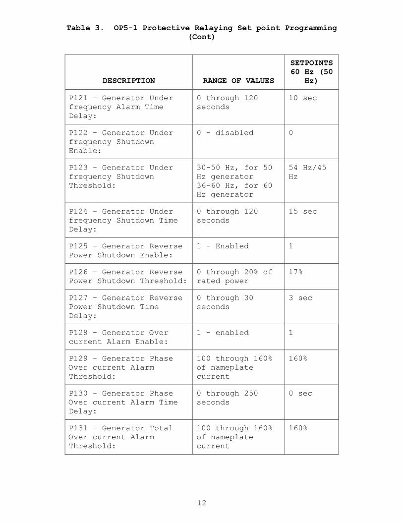
Table 3. OP5-1 Protective Relaying Set point Programming
(Cont)
DESCRIPTION RANGE OF VALUES
SETPOINTS
60 Hz (50
Hz)
P121 – Generator Under
frequency Alarm Time
Delay:
0 through 120
seconds
10 sec
P122 – Generator Under
frequency Shutdown
Enable:
0 – disabled
0
P123 – Generator Under
frequency Shutdown
Threshold:
30-50 Hz, for 50
Hz generator
36-60 Hz, for 60
Hz generator
54 Hz/45
Hz
P124 – Generator Under
frequency Shutdown Time
Delay:
0 through 120
seconds
15 sec
P125 – Generator Reverse
Power Shutdown Enable:
1 – Enabled
1
P126 – Generator Reverse
Power Shutdown Threshold:
0 through 20% of
rated power
17%
P127 – Generator Reverse
Power Shutdown Time
Delay:
0 through 30
seconds
3 sec
P128 – Generator Over
current Alarm Enable:
1 – enabled 1
P129 – Generator Phase
Over current Alarm
Threshold:
100 through 160%
of nameplate
current
160%
P130 – Generator Phase
Over current Alarm Time
Delay:
0 through 250
seconds
0 sec
P131 – Generator Total
Over current Alarm
Threshold:
100 through 160%
of nameplate
current
160%

13
Table 3. OP5-1 Protective Relaying Set point Programming
(Cont)
DESCRIPTION RANGE OF VALUES
SETPOINTS
60 Hz (50
Hz)
P132 – Generator Total
Over current Alarm Time
Delay:
0 through 250
seconds
0 sec
P133 – Generator Over
current Shutdown Enable:
0 – disabled
0
P134 – Generator Phase
Over current Shutdown
Threshold:
100 through 160% 160%
P135 – Generator Phase
Over current Shutdown
Time Delay:
0 through 500
seconds
0 sec
P136 – Generator Total
Over current Shutdown
Threshold:
100 through 160%
of three times
nameplate current
in increments of
5%
160%
P137 – Generator Total
Over current Shutdown
Time Delay:
0 through 500
seconds
0 sec
P138 – KW Level Relay
Enable:
1 – enabled 1
P139 – KW Level Relay
Threshold:
0 through 110% of
nameplate power
110%
P140 – KW Level Relay
Time Delay:
0 through 120
seconds
0 sec
P141 – KW Level Relay
Disengage Threshold:
0 through 110% of
nameplate power
100%
P142 – KW Level Relay
Disengage Time Delay:
0 through 120
seconds
10 sec

14
Table 4. OP5-3 Synchronization Set point Programming
DESCRIPTION RANGE OF VALUES SETPOINTS
P301 – Synchronization
Enable:
1 – Woodward 1
P302 – Breaker Coil Time
Limit: l.
0.2 to 5.0 seconds 1
P303 – Voltage Limit
Enable:
1 – enabled 1
P304 – Voltage Limit: 1% to 15% 4%
P305 – Phase Tolerance
Limit: Maximum phase
angle magnitude allowed
for breaker closure. 2
1 to 25 degrees in
increments of 1
5 deg
P306 – Dwell Time: 0.1 to 1.0 seconds 0.5 sec
P307 – Speed Control Gain: 0.0% to 100.0%
varies
typical
12%
P308 – Speed Control Rate: 0.0% to 100.0%
varies
typical
17%
P309 – Speed Control
Damping:
0.0% to 100.0% in
increments of 0.1%
% varies
typical 8%
P310 – Dead Bus Closure
Enabled:
1 – enabled 1
P311 – Dead Bus Limit: 5% to 50% 20%
P312 – Dead Bus On Time
Delay:
0 to 120 seconds 2 sec
P313 – Frequency Match
Notification Time:
5 to 1000 seconds 20 sec
P314 – Maximum
Synchronization Time:
5 to 1000 seconds 30 sec
15
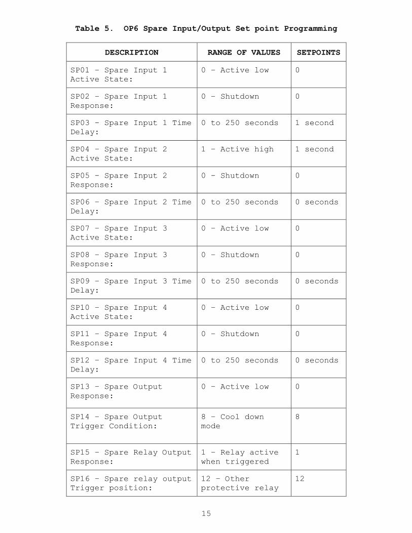
Table 5. OP6 Spare Input/Output Set point Programming
DESCRIPTION RANGE OF VALUES SETPOINTS
SP01 – Spare Input 1
Active State:
0 – Active low
0
SP02 – Spare Input 1
Response:
0 – Shutdown
0
SP03 – Spare Input 1 Time
Delay:
0 to 250 seconds 1 second
SP04 – Spare Input 2
Active State:
1 – Active high
1 second
SP05 – Spare Input 2
Response:
0 – Shutdown
0
SP06 – Spare Input 2 Time
Delay:
0 to 250 seconds 0 seconds
SP07 – Spare Input 3
Active State:
0 – Active low
0
SP08 – Spare Input 3
Response:
0 – Shutdown
0
SP09 – Spare Input 3 Time
Delay:
0 to 250 seconds 0 seconds
SP10 – Spare Input 4
Active State:
0 – Active low
0
SP11 – Spare Input 4
Response:
0 – Shutdown
0
SP12 – Spare Input 4 Time
Delay:
0 to 250 seconds 0 seconds
SP13 – Spare Output
Response:
0 – Active low
0
SP14 – Spare Output
Trigger Condition:
8 – Cool down
mode
8
SP15 – Spare Relay Output
Response:
1 – Relay active
when triggered
1
SP16 – Spare relay output
Trigger position:
12 – Other
protective relay
12
16
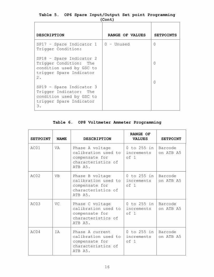
Table 5. OP6 Spare Input/Output Set point Programming
(Cont)
DESCRIPTION RANGE OF VALUES SETPOINTS
SP17 – Spare Indicator 1
Trigger Condition:
SP18 – Spare Indicator 2
Trigger Condition: The
condition used by GSC to
trigger Spare Indicator
2.
SP19 – Spare Indicator 3
Trigger Indicator: The
condition used by GSC to
trigger Spare Indicator
3.
0 – Unused
0
0
0
Table 6. OP8 Voltmeter Ammeter Programming
SETPOINT
NAME
DESCRIPTION
RANGE OF
VALUES
SETPOINT
AC01 VA Phase A voltage
calibration used to
compensate for
characteristics of
ATB A5.
0 to 255 in
increments
of 1
Barcode
on ATB A5
AC02 VB Phase B voltage
calibration used to
compensate for
characteristics of
ATB A5.
0 to 255 in
increments
of 1
Barcode
on ATB A5
AC03 VC Phase C voltage
calibration used to
compensate for
characteristics of
ATB A5.
0 to 255 in
increments
of 1
Barcode
on ATB A5
AC04 IA Phase A current
calibration used to
compensate for
characteristics of
ATB A5.
0 to 255 in
increments
of 1
Barcode
on ATB A5
17
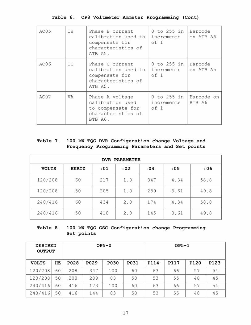
Table 6. OP8 Voltmeter Ammeter Programming (Cont)
AC05 IB Phase B current
calibration used to
compensate for
characteristics of
ATB A5.
0 to 255 in
increments
of 1
Barcode
on ATB A5
AC06 IC Phase C current
calibration used to
compensate for
characteristics of
ATB A5.
0 to 255 in
increments
of 1
Barcode
on ATB A5
AC07 VA Phase A voltage
calibration used
to compensate for
characteristics of
BTB A6.
0 to 255 in
increments
of 1
Barcode on
BTB A6
Table 7. 100 kW TQG DVR Configuration change Voltage and
Frequency Programming Parameters and Set points
DVR PARAMETER
VOLTS HERTZ :01 :02 :04 :05 :06
120/208 60 217 1.0 347 4.34 58.8
120/208 50 205 1.0 289 3.61 49.8
240/416 60 434 2.0 174 4.34 58.8
240/416 50 410 2.0 145 3.61 49.8
Table 8. 100 kW TQG GSC Configuration change Programming
Set points
DESIRED
OUTPUT
OP5-0 OP5-1
VOLTS HZ P028 P029 P030 P031 P114 P117 P120 P123
120/208 60 208 347 100 60 63 66 57 54
120/208 50 208 289 83 50 53 55 48 45
240/416 60 416 173 100 60 63 66 57 54
240/416 50 416 144 83 50 53 55 48 45
18
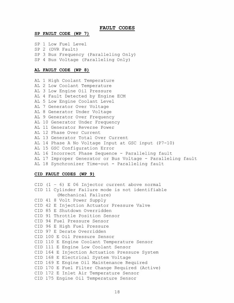
FAULT CODES SP FAULT CODE (WP 7)
SP 1 Low Fuel Level
SP 2 (DVR Fault)
SP 3 Bus Frequency (Paralleling Only)
SP 4 Bus Voltage (Paralleling Only)
AL FAULT CODE (WP 8)
AL 1 High Coolant Temperature
AL 2 Low Coolant Temperature
AL 3 Low Engine Oil Pressure
AL 4 Fault Detected by Engine ECM
AL 5 Low Engine Coolant Level
AL 7 Generator Over Voltage
AL 8 Generator Under Voltage
AL 9 Generator Over Frequency
AL 10 Generator Under Frequency
AL 11 Generator Reverse Power
AL 12 Phase Over Current
AL 13 Generator Total Over Current
AL 14 Phase A No Voltage Input at GSC input (P7-10)
AL 15 GSC Configuration Error
AL 16 Incorrect Phase Sequence - Paralleling fault
AL 17 Improper Generator or Bus Voltage - Paralleling fault
AL 18 Synchronizer Time-out - Paralleling fault
CID FAULT CODES (WP 9)
CID (1 – 6) E 06 Injector current above normal
CID 11 Cylinder Failure mode is not identifiable
(Mechanical Failure)
CID 41 8 Volt Power Supply
CID 42 E Injection Actuator Pressure Valve
CID 85 E Shutdown Overridden
CID 91 Throttle Position Sensor
CID 94 Fuel Pressure Sensor
CID 96 E High Fuel Pressure
CID 97 E Derate Overridden
CID 100 E Oil Pressure Sensor
CID 110 E Engine Coolant Temperature Sensor
CID 111 E Engine Low Coolant Sensor
CID 164 E Injection Actuation Pressure System
CID 168 E Electrical System Voltage
CID 169 E Engine Oil Maintenance Required
CID 170 E Fuel Filter Change Required (Active)
CID 172 E Inlet Air Temperature Sensor
CID 175 Engine Oil Temperature Sensor

19
CID FAULT CODES (WP 9)
CID 190 (FMI) 02 Primary Engine Speed/Timing Sensor
CID 190 (FMI) 03 Magnetic Pickup Unit
CID 190 E Primary (Top) Engine Speed/Timing Sensor
CID 248 CAT Data Link Abnormal update
CID 253 E Personality Module Mismatch
CID 254 E ECM Self Test Failed Component
CID 261 E Engine Timing Calibration
CID 262 E 5 V Sensor Power Supply
CID 264 E E-Stop Shutdown Voltage Above Normal
CID 268 GSC Electronic Control
CID 269 GSC 8V Sensor Power Supply Voltage
CID 273 Turbo Outlet Pressure Sensor
CID 274 Atmospheric Pressure Sensor
CID 334 Spare Output
CID 336 E ENGINE CONTROL Switch (ECS)
CID 342 E Secondary (Bottom) Engine Speed/Timing Sensor
CID 360 E Low Engine Oil Pressure
CID 361 E High Engine Coolant Temperature
CID 362 E Overspeed
CID 368 E High Inlet Air Temperature
CID 390 E Fuel Filter Restriction
CID 391 E Inlet Air Restriction
CID 441 GSC Engine Governor Relay (EGR)
CID 442 GSC Generator Fault Relay (GFR)
CID 443 GSC Crank Termination Relay (CTR)
CID 444 GSC Starter Motor Relay (SMR)
CID 445 GSC Run Relay (RR)
CID 447 GSC Fuel Control Relay (FCR)
CID 448 GSC Programmable Spare Relay (PSR)
CID 500 GSC Failed Component
CID 566 Unexpected Shutdown Improper Mechanical Response
CID 590 Engine Electronic Control Module (ECM)
CID 617 E Intake Air Heater
CID 770 Customer Communication Module (CCM)
CID 858 Close Breaker Output
CID 1038 Speed Adjust
CID 1167 K1 Sense Input
CID 1168 Dead Bus Sense Input
CID 1169 AC Transformer Box (ATB) Sensor
CID 1170 02 Bus Transformer Box (BTB) Sensor
CID 1589 E Turbocharger Air Inlet Pressure Sensor
20
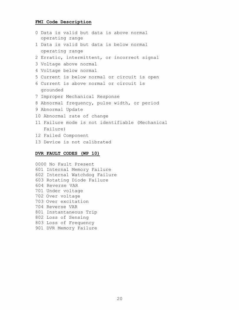
FMI Code Description
0 Data is valid but data is above normal
operating range
1 Data is valid but data is below normal
operating range
2 Erratic, intermittent, or incorrect signal
3 Voltage above normal
4 Voltage below normal
5 Current is below normal or circuit is open
6 Current is above normal or circuit is
grounded
7 Improper Mechanical Response
8 Abnormal frequency, pulse width, or period
9 Abnormal Update
10 Abnormal rate of change
11 Failure mode is not identifiable (Mechanical
Failure)
12 Failed Component
13 Device is not calibrated
DVR FAULT CODES (WP 10)
0000 No Fault Present
601 Internal Memory Failure
602 Internal Watchdog Failure
603 Rotating Diode Failure
604 Reverse VAR
701 Under voltage
702 Over voltage
703 Over excitation
704 Reverse VAR
801 Instantaneous Trip
802 Loss of Sensing
803 Loss of Frequency
901 DVR Memory Failure

21
Fault Log Viewing
To view the fault log use the following steps.
a. Set the ECS to COOLDOWN/STOP b. Press SERVICE MODE key on GSC keypad. SERV will be
displayed on upper display. OP1 will be displayed on the
lower display.
c. Press LAMP TEST key on keypad. If more than one
diagnostic code is present, codes will scroll on display.
The number of occurrences is shown above the COUNT
indicator. The lower display shows value from the hour
meter at the first occurrence and the last occurrence of
each diagnostic code.
d. Press LAMP TEST key to stop scrolling. e. Press POWER METER key. If more than one count of a
diagnostic code is logged, the first occurrence with a
corresponding value from the hour meter shows on the lower
display.
f. Press LAMP TEST key. Diagnostic codes continue
scrolling.
g. Press EXIT key. OP1 shows on lower display.
h. Press EXIT to return display to normal mode.
Transient Codes During Troubleshooting
During troubleshooting, if the harness will be
disconnected from the rear of the GSC (A1 P7). This action
will cause failure codes unrelated to the actual failure
to appear.
CID 100 FMI 02 engine oil pressure sensor
CID 110 FMI 02 engine coolant temperature sensor
CID 111 FMI 03 engine coolant level sensor
CID 175 FMI 03 engine oil temperature sensor
CID 190 FMI 03 engine speed sensor
CID 336 FMI 02 ENGINE CONTROL switch

22
Fault Log Clearing
To clear Fault codes use the following steps.
a. Enter the GSC password.
b. Scroll to parameter OP 4.
c. Press LAMP TEST. The last CID FMI fault that occurred
and the number of occurrences will be displayed. The lower
display shows the hour meter values of the first and the
last occurrence of the fault.
d. Press LAMP TEST. The CID FMI fault code, hour meter
value, and fault count will flash.
e. Press and hold ALARM CODES.
f. If there was only one CID FMI fault code, the CID FMI
fault that was flashing will disappear and the upper
display will be blank except for flashing SERV indicator.
OP1 is shown on lower display. Press the EXIT key. The
display will be in normal mode.
g. If there is more than one CID FMI fault code, the CID FMI
that was flashing disappears. The upper display shows the
next CIF FMI fault code, fault count, and the hour meter
value. Repeat steps d. and e. until all faults are erased.
The lower display then shows OP1. Press the EXIT key. The
display will be in normal mode.
DVR Fault Codes
DVR Fault codes are stored in Parameters.
Parameter :92 - Latest fault. Contains the code for the
most recently declared, or current, fault that has occurred
after the last fault was reset. It may contain either alarm
or shutdown faults.
Parameter :93 - Previous fault. Contains the fault code for
the previous fault that was in parameter :92. The alarm
code that was in parameter :92 would be moved here and any
code that was here is overwritten.
Parameter :94 - Fault Clear. This parameter acts like a
switch to clear fault codes from latest fault parameter
:92. The code that was in parameter :92 is moved to
parameter :93 (previous fault) overwriting the code that
was there and parameter :92 is returned to 0000.
Parameter :96 - Shutdown Fault Reset. Acts like a switch
to reset an active shutdown fault. This will allow the DVR
to begin regulation again and stop the display from
flashing the fault code.

23
Clearing DVR Fault Codes
To clear DVR Fault codes use the following steps.
a. Select Parameter :94.
b. Press the function key the display will flash three
times.
c. The code that is in Parameter :92 is moved to Parameter
:93 overwriting the code that was there. Parameter :92 is
returned to 0000.
d. The display will return to :01.
To reset a DVR shutdown Fault use the following steps.
a. Select Parameter :96.
b. Press the function key the display will flash three
times.
c. The DVR will begin regulation again, the display will
stop flashing, and the display will return to parameter :01.

24