(mems) physical fundamentals - people - rochester institute of
TRANSCRIPT

© January 3, 2017, Dr. Lynn Fuller, Professor
Rochester Institute of Technology
Microelectronic Engineering
MEMs Mechanical Fundamentals
Page 1
ROCHESTER INSTITUTE OF TEHNOLOGYMICROELECTRONIC ENGINEERING
1-3-2017 mem_mech.ppt
Microelectromechanical Systems (MEMs)Mechanical Fundamentals
Dr. Risa Robinson and Dr. Lynn Fuller
Webpage: http://people.rit.edu/lffeeeMicroelectronic Engineering
Rochester Institute of Technology82 Lomb Memorial Drive
Rochester, NY 14623-5604Email: [email protected]
Program webpage: http://www.rit.edu/microelectronic/
© January 3, 2017, Dr. Lynn Fuller, Professor
Rochester Institute of Technology
Microelectronic Engineering
MEMs Mechanical Fundamentals
Page 2
OUTLINE
Force
Pressure
Stress, Strain and Hooke’s Law
Poisson’s Ratio
Simple Cantilever
Springs
Thermal Strain
Bi-metalic Actuator
Diaphragm

© January 3, 2017, Dr. Lynn Fuller, Professor
Rochester Institute of Technology
Microelectronic Engineering
MEMs Mechanical Fundamentals
Page 3
FORCE
F = ma (newton)
where m is mass in Kg
a is acceleration in m/sec2
gravitational acceleration is 9.8 m/sec2
How do you convert dynes to newtons?
N 1000gm 100cm / s2
--- = ---------------------- so 1 newton = 105 dynes
dyne 1gm 1 cm /s2
newton (N) = 1 Kg 1 meter/s2
dyne = 1 gm 1 cm/s2

© January 3, 2017, Dr. Lynn Fuller, Professor
Rochester Institute of Technology
Microelectronic Engineering
MEMs Mechanical Fundamentals
Page 4
PRESSURE
Pressure is used to describe force per unit area.
P = F/A
Pressure due to the weight of liquid
P = h d g where h is the height
d is the density of the liquid
g is acceleration due to gravity
980 cm/sec2
© January 3, 2017, Dr. Lynn Fuller, Professor
Rochester Institute of Technology
Microelectronic Engineering
MEMs Mechanical Fundamentals
Page 5
PRESSURE UNITS
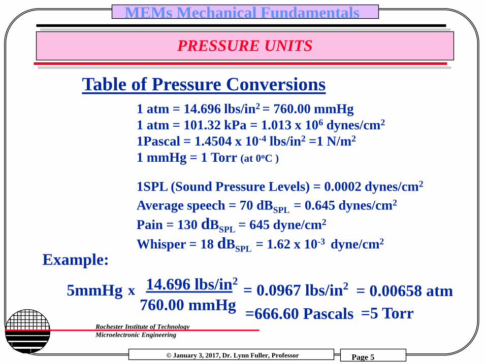
Table of Pressure Conversions
1 atm = 14.696 lbs/in2 = 760.00 mmHg
1 atm = 101.32 kPa = 1.013 x 10⁶ dynes/cm2
1Pascal = 1.4504 x 10⁻⁴ lbs/in2 =1 N/m2
1 mmHg = 1 Torr (at 0oC )
1SPL (Sound Pressure Levels) = 0.0002 dynes/cm2
Average speech = 70 dBSPL = 0.645 dynes/cm2
Pain = 130 dBSPL = 645 dyne/cm2
Whisper = 18 dBSPL = 1.62 x 10⁻³ dyne/cm2
Example:
5mmHg x 14.696 lbs/in2 = 0.0967 lbs/in2
760.00 mmHg= 0.00658 atm
=666.60 Pascals =5 Torr
© January 3, 2017, Dr. Lynn Fuller, Professor
Rochester Institute of Technology
Microelectronic Engineering
MEMs Mechanical Fundamentals
Page 6
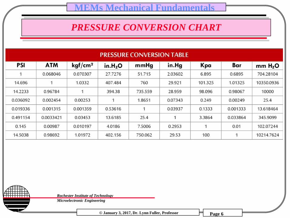
PRESSURE CONVERSION CHART

© January 3, 2017, Dr. Lynn Fuller, Professor
Rochester Institute of Technology
Microelectronic Engineering
MEMs Mechanical Fundamentals
Page 7
GAUGE PRESSURE – ABSOLUTE PRESSURE
Gauge pressure is a differential pressure measured relative to an
ambient pressure. The output of a gauge pressure sensor is not
sensitive to a changing barometric pressure
Absolute pressure is differential pressure measured relative to an
absolute zero pressure (perfect vacuum). The output of the
absolute sensor will change as a result of barometric pressure
change and thus can be used as a barometer.

© January 3, 2017, Dr. Lynn Fuller, Professor
Rochester Institute of Technology
Microelectronic Engineering
MEMs Mechanical Fundamentals
Page 8
HOOKE’S LAW
Stress is the applied force per crossectional area, = F/A
Strain is the elongation per unit length, = L/L
y = yield strength
u = ultimate or maximum strength
b = rupture strength ( for brittle material u = b)
Strain,
Stress,
x u
y = E
where
E is Young’s modulus

© January 3, 2017, Dr. Lynn Fuller, Professor
Rochester Institute of Technology
Microelectronic Engineering
MEMs Mechanical Fundamentals
Page 9
STRESS - COMPRESSIVE, TENSILE
Stress is the force per unit area applied to a mechanical member (Pressure)
A positive sign will be used to indicate a tensile stress (member in tension) and a negative sign to indicate a compressive stress (member in compression)
These forces can be axial, transverse, oblique, shearing, torsional, thermal, etc
Thickness = 10 µmDiameter 75 mm

© January 3, 2017, Dr. Lynn Fuller, Professor
Rochester Institute of Technology
Microelectronic Engineering
MEMs Mechanical Fundamentals
Page 10
POISSON’S RATIO
Poisson’s ratio () gives the relationship between lateral strain
and axial strain. In all engineering materials the elongation
produced by an axial tensile force in the direction of the force is
accompanied by a contraction in any transverse direction.
= - y / x ~ 0.3
X, Axial
Force x
y
Original
Deformed

© January 3, 2017, Dr. Lynn Fuller, Professor
Rochester Institute of Technology
Microelectronic Engineering
MEMs Mechanical Fundamentals
Page 11
PROPERTIES OF SOME MATERIALS
y u E d Yield Ultimate Knoop Youngs Density Thermal Thermal Poisso’s
Strength Hardness Modulus (gr/cm3) Conductivity Expansion Ratio
(1010 dyne/cm2) (Kg/mm2) (1012dyne/cm2) (w/cm°C) (10-6/°C)
Si3N4 14 28 3486 3.85 3.1 0.19 0.8 0.3
SiO2 8.4 16 820 0.73 2.5 0.014 0.55 0.3
Si 12 14 850 1.9 2.3 1.57 2.33 0.32
Al 0.17 130 0.68 2.7 2.36 25 0.334
10 dyne/cm2 = 1 newton/m2

© January 3, 2017, Dr. Lynn Fuller, Professor
Rochester Institute of Technology
Microelectronic Engineering
MEMs Mechanical Fundamentals
Page 12
HARDNESS
Hardness is a well known physical parameter, but many different methods have been derived for the measurement and classification of materials on a hardness scale. The Knoop scale is the most commonly used, others being: Moh, Vickers, Rockwell and Brinell.
The experimental procedure for the derivation of a value on the Knoop scale is to use a pyramidal diamond point which is pressed into the material in question with a known force. The indentation made by the point is then measured and the Knoopnumber calculated from this measurement. A soft material would have a Knoop number of 4, whereas a hard material like sapphire has a Knoop number of 2000 and the Knoop number for diamond is 7000.

© January 3, 2017, Dr. Lynn Fuller, Professor
Rochester Institute of Technology
Microelectronic Engineering
MEMs Mechanical Fundamentals
Page 13
STRESS IN SPUTTERED FILMS
Compressively stressed films would like to expand parallel to the substrate surface, and in the extreme, films in compressive stress will buckle up on the substrate. Films in tensile stress, on the other hand, would like to contract parallel to the substrate, and may crack if their elastic limits are exceeded. In general stresses in films range from 1E8 to 5E10 dynes/cm2.
For AVT sputtered oxide films Dr. Grande found Compressive18MPa stress, 1-29-2000
10 dyne/cm2 = 1 newton/m2 = 1 Pascal
compressive
tensile

© January 3, 2017, Dr. Lynn Fuller, Professor
Rochester Institute of Technology
Microelectronic Engineering
MEMs Mechanical Fundamentals
Page 14
MEASUREMENT OF STRESS IN Si3N4
Kenneth L. Way, Jr. did his senior project on stress in silicon nitride films as a function of the ratio of ammonia to dichlorosilane. Samples were coated with various flows and stress was measured at ADE corporation. The silicon nitride was etched off of the backside of the wafer so that the stress curvature was due to the layer on the front side only. Dr. Lane said the nitride runs at 1:10 (ammonia:dichlorosilane) ratios are rough on the pumping system.
Dr. Grande sent samples to Kodak for stress measurement. He found stress of 900 MPa Tensile for the standard Nitride recipe for 1500 A thickness, 1-29-2000
Compressive Stress Tensile Stress
10 dyne/cm2 = 1 newton/m2 = 1 Pascal

© January 3, 2017, Dr. Lynn Fuller, Professor
Rochester Institute of Technology
Microelectronic Engineering
MEMs Mechanical Fundamentals
Page 15
LOW STRESS SILICON RICH Si3N4
ADE Measured stress for various Ammonia:Dichlorosilane Flow Ratios
Flow Stress x E 9 dynes/cm210:1 + 14.635:1 + 14.812.5:1 + 12.47 Stress; = (E/(6(1-v)))*(D2/(rt)) 1:1 + 10.13 where E is Youngs modulus, 1:2.5 + 7.79* v is Poissons ratio, 1:5 + 3 D and t are substrate and film thickness1:10 0 r is radius of curvature (+ for tensile)*standard recipe
T.H Wu, “Stress in PSG and Nitride Films as Related to Film Properties and Annealing”, Solid State Technology, p 65-71,May ‘92
10 dyne/cm2 = 1 newton/m2 = 1 Pascal

© January 3, 2017, Dr. Lynn Fuller, Professor
Rochester Institute of Technology
Microelectronic Engineering
MEMs Mechanical Fundamentals
Page 16
STRESS IN SILICON NITRIDE FILMS
Stress in an 8000 A
Nitride Film
Tensile Stress
© January 3, 2017, Dr. Lynn Fuller, Professor
Rochester Institute of Technology
Microelectronic Engineering
MEMs Mechanical Fundamentals
Page 17
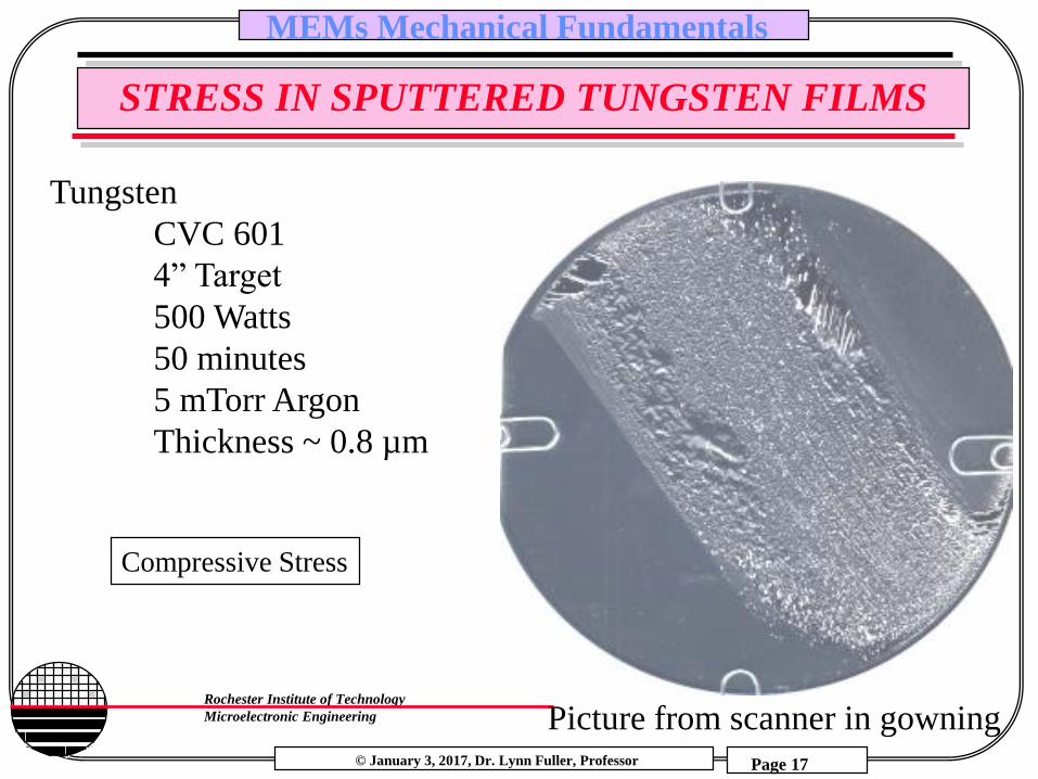
STRESS IN SPUTTERED TUNGSTEN FILMS
Picture from scanner in gowning
Tungsten
CVC 601
4” Target
500 Watts
50 minutes
5 mTorr Argon
Thickness ~ 0.8 µm
Compressive Stress
© January 3, 2017, Dr. Lynn Fuller, Professor
Rochester Institute of Technology
Microelectronic Engineering
MEMs Mechanical Fundamentals
Page 18
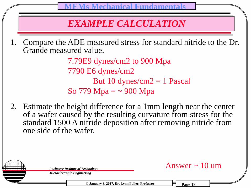
EXAMPLE CALCULATION
1. Compare the ADE measured stress for standard nitride to the Dr. Grande measured value.
2. Estimate the height difference for a 1mm length near the center of a wafer caused by the resulting curvature from stress for the standard 1500 A nitride deposition after removing nitride from one side of the wafer.
7.79E9 dynes/cm2 to 900 Mpa
7790 E6 dynes/cm2
But 10 dynes/cm2 = 1 Pascal
So 779 Mpa = ~ 900 Mpa
Answer ~ 10 um

© January 3, 2017, Dr. Lynn Fuller, Professor
Rochester Institute of Technology
Microelectronic Engineering
MEMs Mechanical Fundamentals
Page 19
SIMPLE CANTILEVER
FCantilever:
L
Ymax
Ymax = F L3/3EI
where E = Youngs Modulus
and I = bh3/12, moment of inertia
h
b
Mechanics of Materials, by Ferdinand P. Beer,
E. Russell Johnston, Jr., McGraw-Hill Book Co.1981

© January 3, 2017, Dr. Lynn Fuller, Professor
Rochester Institute of Technology
Microelectronic Engineering
MEMs Mechanical Fundamentals
Page 20
FORCE TO BEND CANTILEVER EXAMPLE
Example: Find the force needed to bend a simple
polysilicon cantilever 1 µm, with the following
parameters: b=4 µm, h=2µm, L=100 µm
Ymax 3 E bh3
F =12L3
(1e-6) 3 ( 1.9e11)(4e-6)(2e-6)3
F =12 (100e-6)3
F = 1.5e-6 newtons

© January 3, 2017, Dr. Lynn Fuller, Professor
Rochester Institute of Technology
Microelectronic Engineering
MEMs Mechanical Fundamentals
Page 21
FORCE TO BEND CANTILEVER EXAMPLE

© January 3, 2017, Dr. Lynn Fuller, Professor
Rochester Institute of Technology
Microelectronic Engineering
MEMs Mechanical Fundamentals
Page 22
STRESS IN A CANTILEVER BEAM
The maximum stress is at the top surface of the
cantilever beam at the anchor where x=0
x=0 = F Lh/2I where I = bh3/12, moment of inertia
L Ymax
F
h
b
x=0x
Mechanics of Materials, by Ferdinand P. Beer,
E. Russell Johnston, Jr., McGraw-Hill Book Co.1981
© January 3, 2017, Dr. Lynn Fuller, Professor
Rochester Institute of Technology
Microelectronic Engineering
MEMs Mechanical Fundamentals
Page 23
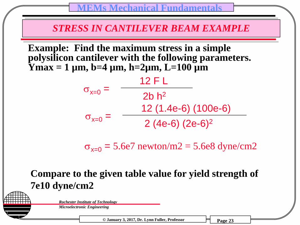
STRESS IN CANTILEVER BEAM EXAMPLE
Example: Find the maximum stress in a simple polysilicon cantilever with the following parameters. Ymax = 1 µm, b=4 µm, h=2µm, L=100 µm
12 F Lx=0 =
2b h2
Compare to the given table value for yield strength of
7e10 dyne/cm2
12 (1.4e-6) (100e-6)x=0 =
2 (4e-6) (2e-6)2
x=0 = 5.6e7 newton/m2 = 5.6e8 dyne/cm2

© January 3, 2017, Dr. Lynn Fuller, Professor
Rochester Institute of Technology
Microelectronic Engineering
MEMs Mechanical Fundamentals
Page 24
FORCE TO BEND CANTILEVER EXAMPLE
© January 3, 2017, Dr. Lynn Fuller, Professor
Rochester Institute of Technology
Microelectronic Engineering
MEMs Mechanical Fundamentals
Page 25
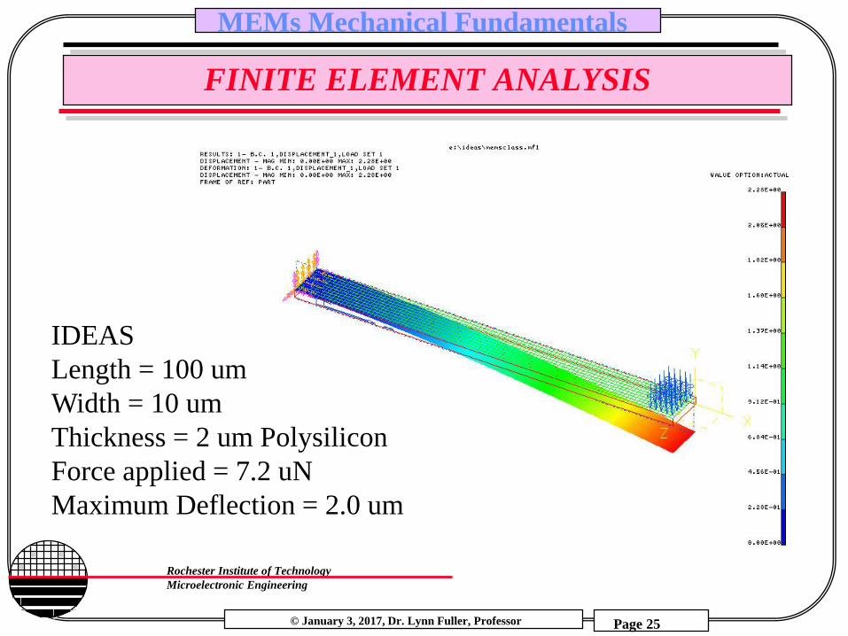
FINITE ELEMENT ANALYSIS
IDEAS
Length = 100 um
Width = 10 um
Thickness = 2 um Polysilicon
Force applied = 7.2 uN
Maximum Deflection = 2.0 um

© January 3, 2017, Dr. Lynn Fuller, Professor
Rochester Institute of Technology
Microelectronic Engineering
MEMs Mechanical Fundamentals
Page 26
ACCELEROMETER - EXAMPLE
The proof mass will create a force in the presence of an acceleration, the strain can be measured with a piezoresistive device or the position can be measured with a capacitive measurement device
L Ymax
Proof Mass
hb
x=0x

© January 3, 2017, Dr. Lynn Fuller, Professor
Rochester Institute of Technology
Microelectronic Engineering
MEMs Mechanical Fundamentals
Page 27
ACCELEROMETER-EXAMPLE
Example: from previous cantilever example
Ymax 3 E bh3
F =12L3
F = 1.5e-6 newtons
Find height X for a proof mass of volume (V) of nickel (density (d)=8.91 gm/cm3) and maximum acceleration of 50G’s
F = mA = m 50 (9.8m/s2) = 1.5e-6 newtons
and find m = 3.1e-9 Kgm = 3.1e-6 gm
m = d V =3.1e-6 = (8.91)(25e-4)(25e-4)(X) cm
X = 0.055cm = 550µm
Approximately the thickness of a 4” wafer
25 µm
X µm
25 µm
m
m=dV

© January 3, 2017, Dr. Lynn Fuller, Professor
Rochester Institute of Technology
Microelectronic Engineering
MEMs Mechanical Fundamentals
Page 28
CANTILEVER.XLS
© January 3, 2017, Dr. Lynn Fuller, Professor
Rochester Institute of Technology
Microelectronic Engineering
MEMs Mechanical Fundamentals
Page 29
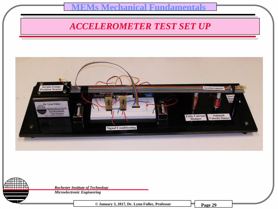
ACCELEROMETER TEST SET UP

© January 3, 2017, Dr. Lynn Fuller, Professor
Rochester Institute of Technology
Microelectronic Engineering
MEMs Mechanical Fundamentals
Page 30
SPREAD SHEET FOR ACCELEROMETER CALCULATIONS

© January 3, 2017, Dr. Lynn Fuller, Professor
Rochester Institute of Technology
Microelectronic Engineering
MEMs Mechanical Fundamentals
Page 31
SPREAD SHEET FOR ACCELEROMETER CALCULATIONS

© January 3, 2017, Dr. Lynn Fuller, Professor
Rochester Institute of Technology
Microelectronic Engineering
MEMs Mechanical Fundamentals
Page 32
CALCULATED PLOT OF VOUT VS. TIME
Vout vs. Time
-0.00000015
-0.0000001
-0.00000005
0
0.00000005
0.0000001
0.00000015
0 0.5 1 1.5 2 2.5 3 3.5 4 4.5
Time (sec)
Vo
ut (v
olts
)

© January 3, 2017, Dr. Lynn Fuller, Professor
Rochester Institute of Technology
Microelectronic Engineering
MEMs Mechanical Fundamentals
Page 33
FINITE ELEMENT ANALYSIS (FEA) OF CANTILEVER
F = 1 NYmax = 10 umStress = 3.8E5 N/m2
F = 1 NYmax = 1.6 umStress = 7.2E3 N/m2
Burak Baylav
Length = 1500 µmWidth = 600 µmThickness = 20 µmWindow ~ 300 x 300 µm
SolidWorks

© January 3, 2017, Dr. Lynn Fuller, Professor
Rochester Institute of Technology
Microelectronic Engineering
MEMs Mechanical Fundamentals
Page 34
SPRINGS
F = k y where k is the spring constant
and y is the displacement
Cantilever:
L
Ymax
Ymax = F L3/3EI
where E = Youngs Modulus
and I = bh3/12, moment of inertia
h
b
FF = k y
F = (3E(bh3/12)/ L3) y
Analogy: I = G V
k is like conductance (G)
I is Force, V is potential
k

© January 3, 2017, Dr. Lynn Fuller, Professor
Rochester Institute of Technology
Microelectronic Engineering
MEMs Mechanical Fundamentals
Page 35
CAPACITIVE ELECTROSTATIC FORCE
F
++++++++
- - - - - - -
The energy stored in a capacitorcan be equated to the force timesdistance between the plates
W = Fd or F = W/d
2d2
o r A V2F =
d
area A
Energy stored in a parallel plate capacitor W
with area A and space between plates of d
W = 0.5 QV = 0.5 CV2
since Q = CV
d
or AC =
opermitivitty of free space = 8.85e-12 Farads/m
r = relative permitivitty (for air r = 1)

© January 3, 2017, Dr. Lynn Fuller, Professor
Rochester Institute of Technology
Microelectronic Engineering
MEMs Mechanical Fundamentals
Page 36
ELECTROSTATIC PULL-IN VOLTAGE
Example: Two parallel plates a distance d apart, one fixed, one movable with spring constant k. An applied voltage causes a force that works against the spring. At a high enough voltage (Vpull-in) the system becomes unstable and the plates come together.
27or AreaVpull-in =
8 k d3
If the spring is a cantilever and the plates have an area of A, the pull in voltage is found from the equation above where k is
k = (3E(bh3/12)/ L3)

© January 3, 2017, Dr. Lynn Fuller, Professor
Rochester Institute of Technology
Microelectronic Engineering
MEMs Mechanical Fundamentals
Page 37
FOLDED SPRING
2nd layer poly
I
100 x100 µm
pads
40 µm
2nd layer poly
I
100 x100 µm
pads
40 µm
k total =k k total =k/2

© January 3, 2017, Dr. Lynn Fuller, Professor
Rochester Institute of Technology
Microelectronic Engineering
MEMs Mechanical Fundamentals
Page 38
FOLDED SPRING EXAMPLE
Example: Calculate the force needed to elongate the spring
shown by 50 µm. Assume each arm of the spring is 400 µm
in length and the polysilicon thickness is 2 µm.
2nd layer poly
I
100 x100 µm
pads
40 µm

© January 3, 2017, Dr. Lynn Fuller, Professor
Rochester Institute of Technology
Microelectronic Engineering
MEMs Mechanical Fundamentals
Page 39
BEAM ANCHORED AT BOTH ENDS
F
L/2
Ymax
Ymax = F L3/48EI
where E = Youngs Modulus
and I = bh3/12, moment of inertia
h
b
Mechanics of Materials, by Ferdinand P. Beer,
E. Russell Johnston, Jr., McGraw-Hill Book Co.1981
© January 3, 2017, Dr. Lynn Fuller, Professor
Rochester Institute of Technology
Microelectronic Engineering
MEMs Mechanical Fundamentals
Page 40
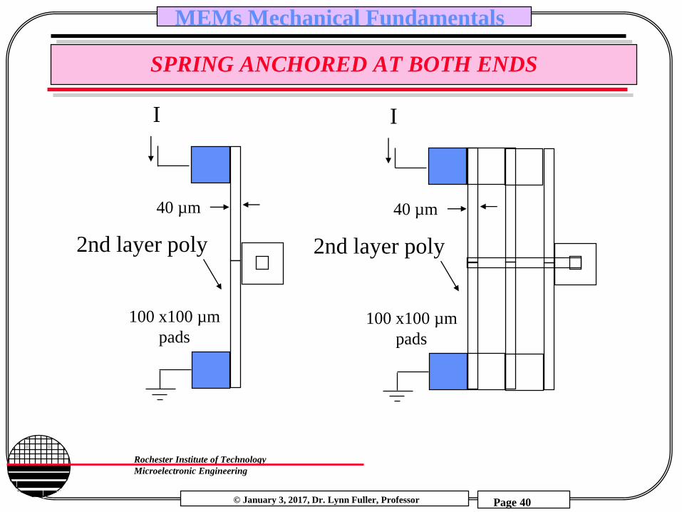
SPRING ANCHORED AT BOTH ENDS
2nd layer poly
I
100 x100 µm
pads
40 µm
2nd layer poly
I
100 x100 µm
pads
40 µm

© January 3, 2017, Dr. Lynn Fuller, Professor
Rochester Institute of Technology
Microelectronic Engineering
MEMs Mechanical Fundamentals
Page 41
THERMAL STRAIN
The fractional change in length due to a change in temperature is given by:
L/L = (T) where is the coefficient of thermal expansion
This is also the thermal strain T. In this case the strain does not cause a stress unless the material is confined in some way

© January 3, 2017, Dr. Lynn Fuller, Professor
Rochester Institute of Technology
Microelectronic Engineering
MEMs Mechanical Fundamentals
Page 42
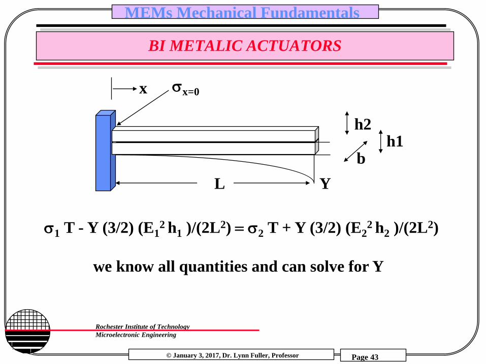
BI METALIC ACTUATORS
Consider two materials bonded together forming a composite beam. Since the materials are bonded together the change in length for both materials is equal (at boundary)
L1 = L2
each material experiences a thermal strain plus a strain due to the stress caused by the different thermal coefficients,
L/L = T +/EThe material with the larger thermal coefficient will experience a compressive stress (-) while the other material will experience a tensile (+) stress.This results in:
T +1/E12T + 2 /E2and 1-2
© January 3, 2017, Dr. Lynn Fuller, Professor
Rochester Institute of Technology
Microelectronic Engineering
MEMs Mechanical Fundamentals
Page 43
BI METALIC ACTUATORS
1 T - Y (3/2) (E12 h1 )/(2L2) 2 T + Y (3/2) (E2
2 h2 )/(2L2)
we know all quantities and can solve for Y
L Y
h1b
x=0x
h2

© January 3, 2017, Dr. Lynn Fuller, Professor
Rochester Institute of Technology
Microelectronic Engineering
MEMs Mechanical Fundamentals
Page 44
EXAMPLE - BI METALIC ACTUATORS
First find the radius of curvature to achieve a displacement of 1 µm
Tan = Y/L and
the circumference C =2r
and the ratio of: L/C = /
gives r=6.258 cm
Next we look at the composite structure
We need to find the centroid of an equivalent
beam composed of only one of the two materials
L Y
x=0x
To replace the Aluminum with silicon we multiply the width of the
Aluminum by the ratio of the modulus of Al to the modulus of Si
Wal = (25 µm)70e9/190e9
= 9.21 µm
Si
Al
Wsi=25 µm
h1
h2
h1
h2
Wsi
Wal the centroid of this structure
(with respect to the junction) is
(Wsi/2)h12 - (Wal/2) h22
(Wsi/2)h1 + (Wal/2) h2

© January 3, 2017, Dr. Lynn Fuller, Professor
Rochester Institute of Technology
Microelectronic Engineering
MEMs Mechanical Fundamentals
Page 45
EXAMPLE - BI METALIC ACTUATORS
The centroid is the neutral axis of the composite beam. The length of the
neutral axis never changes, NA= 0 , Y is the distance from the neutral axis to
the junction thus Y and are equivalent.
(Wsi/2)h12 - (Wal/2) h22
Y (Wsi/2)h1 + (Wal/2) h2
Total Stress = Thermal Stress + Mechanical Stress
Thermal Stress = T E
Mechanical Stress = E and = Y/r
Stress in Si must equal the Stress in Al
T E1 + E1 = 2T E2 + E2
T E1 + (Y/r) E1 = 2T E2 + (Y/r) E2
we can find Y
for a given h1 we can find h2, let h1=2µm we find h2 = 8 µm

© January 3, 2017, Dr. Lynn Fuller, Professor
Rochester Institute of Technology
Microelectronic Engineering
MEMs Mechanical Fundamentals
Page 46
BIMETALIC CANTILEVER BEAM
Aluminum
Silicon
100μm
10μm
ANSYS – Rob Manley

© January 3, 2017, Dr. Lynn Fuller, Professor
Rochester Institute of Technology
Microelectronic Engineering
MEMs Mechanical Fundamentals
Page 47
RAISE TEMPERATURE FROM 20 TO 200 C
ANSYS – Rob Manley

© January 3, 2017, Dr. Lynn Fuller, Professor
Rochester Institute of Technology
Microelectronic Engineering
MEMs Mechanical Fundamentals
Page 48
MOVIE OF TOTAL DEFORMATION
ANSYS – Rob Manley

© January 3, 2017, Dr. Lynn Fuller, Professor
Rochester Institute of Technology
Microelectronic Engineering
MEMs Mechanical Fundamentals
Page 49
FINITE ELEMENT ANALYSIS OF THERMAL BENDING
Small arm 300 C, 10um X 100 um
Large arm 0 C, 30 um x 100 um
Maximum Displacement = 6 um
IDEAS – Andrew Randall

© January 3, 2017, Dr. Lynn Fuller, Professor
Rochester Institute of Technology
Microelectronic Engineering
MEMs Mechanical Fundamentals
Page 50
TORSIONAL MIRROR
Round Cross Section Torsional Springs
where
f is angle in radians that it will twist
T is Torsion, Force x R
L is Length of round support
G is shear modulus, ~1/3 Young's modulus
J is polar moment of inertia,
for round cross section pr4/2
r is radius of bar
f = T L/(GJ)L
R
F Radius r

© January 3, 2017, Dr. Lynn Fuller, Professor
Rochester Institute of Technology
Microelectronic Engineering
MEMs Mechanical Fundamentals
Page 51
EXCELL DIAPHRAGM CALCULATIONS
Ymax deflection at center
Stress at edge
Capacitance between
diaphragm and substrate
Electrostatic Force
Pull-in Voltage
Resonant Frequency

© January 3, 2017, Dr. Lynn Fuller, Professor
Rochester Institute of Technology
Microelectronic Engineering
MEMs Mechanical Fundamentals
Page 52
FINITE ELEMENT ANALYSIS
Points of
Maximum Stress
IDEAS – Rob Manley
© January 3, 2017, Dr. Lynn Fuller, Professor
Rochester Institute of Technology
Microelectronic Engineering
MEMs Mechanical Fundamentals
Page 53
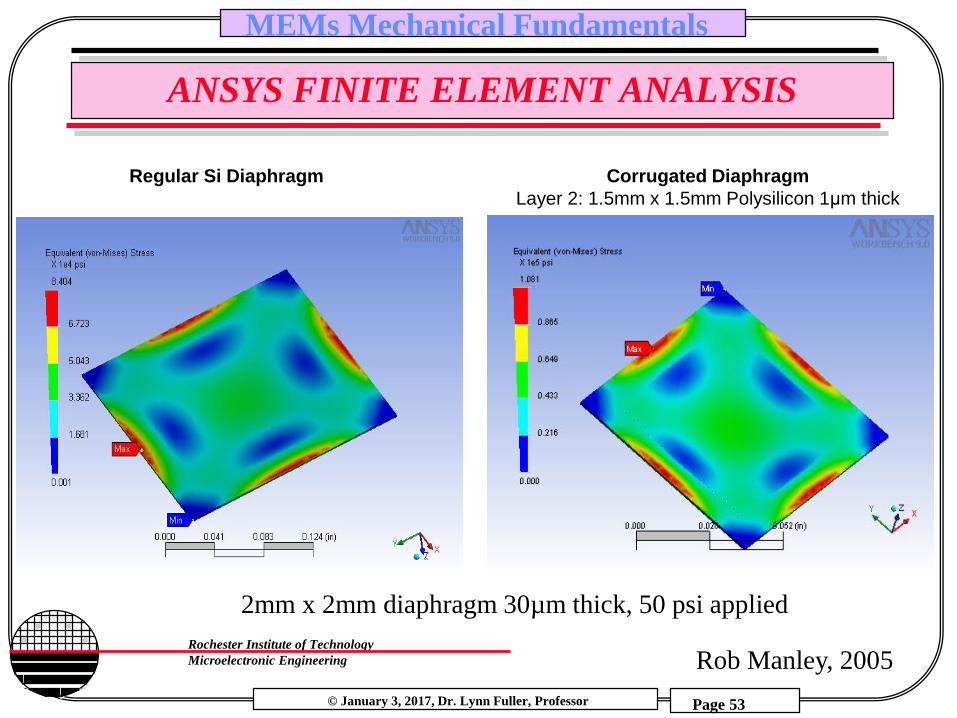
ANSYS FINITE ELEMENT ANALYSIS
Regular Si Diaphragm Corrugated Diaphragm
Layer 2: 1.5mm x 1.5mm Polysilicon 1μm thick
2mm x 2mm diaphragm 30µm thick, 50 psi applied
Rob Manley, 2005

© January 3, 2017, Dr. Lynn Fuller, Professor
Rochester Institute of Technology
Microelectronic Engineering
MEMs Mechanical Fundamentals
Page 54
DIAPHRAGM DEFORMATION MOVIE
Rob Manley, 2005
200µm

© January 3, 2017, Dr. Lynn Fuller, Professor
Rochester Institute of Technology
Microelectronic Engineering
MEMs Mechanical Fundamentals
Page 55
DIAPHRAGM STRESS MOVIE
Rob Manley, 2005

© January 3, 2017, Dr. Lynn Fuller, Professor
Rochester Institute of Technology
Microelectronic Engineering
MEMs Mechanical Fundamentals
Page 56
RESISTOR LAYOUT
R1R3
R2
R4
Two resistors parallel to edge near region of maximum stress and two resistors perpendicular to the edge arranged in a full bridge circuit. If all resistors are of equal value then Vout = Vo1-Vo2 = zero with no pressure applied.
Vo1
Vo2Gnd
Vsupply

© January 3, 2017, Dr. Lynn Fuller, Professor
Rochester Institute of Technology
Microelectronic Engineering
MEMs Mechanical Fundamentals
Page 57
CALCULATION OF EXPECTED OUTPUT VOLTAGE
R1R3
R2R4
Gnd
+5 Volts Vo2
Vo1
The equation for stress at the center
edge of a square diaphragm (S.K.
Clark and K.Wise, 1979)
Stress = 0.3 P(L/H)2 where P is
pressure, L is length of diaphragm
edge, H is diaphragm thickness
For a 3000µm opening on the back of
the wafer the diaphragm edge length L
is 3000 – 2 (500/Tan 54.74°) = 2246
µm

© January 3, 2017, Dr. Lynn Fuller, Professor
Rochester Institute of Technology
Microelectronic Engineering
MEMs Mechanical Fundamentals
Page 58
CALCULATION OF EXPECTED OUTPUT VOLTAGE
Stress = 0.3 P (L/H)2
If we apply vacuum to the back of the wafer that is equivalent to
and applied pressure of 14.7 psi or 103 N/m2
P = 103 N/m2
L= 2246 µm
H= 25 µmStress = 2.49E8 N/m2
Hooke’s Law: Stress = E Strain where E is Young’s Modulus
= E
Young’s Modulus of silicon is 1.9E11 N/m2
Thus the strain = 1.31E-3 or .131%
© January 3, 2017, Dr. Lynn Fuller, Professor
Rochester Institute of Technology
Microelectronic Engineering
MEMs Mechanical Fundamentals
Page 59
CALCULATION OF EXPECTED OUTPUT VOLTAGE
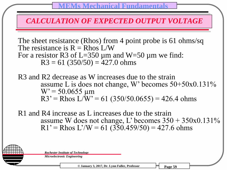
The sheet resistance (Rhos) from 4 point probe is 61 ohms/sqThe resistance is R = Rhos L/WFor a resistor R3 of L=350 µm and W=50 µm we find:
R3 = 61 (350/50) = 427.0 ohms
R3 and R2 decrease as W increases due to the strainassume L is does not change, W’ becomes 50+50x0.131%W’ = 50.0655 µmR3’ = Rhos L/W’ = 61 (350/50.0655) = 426.4 ohms
R1 and R4 increase as L increases due to the strainassume W does not change, L’ becomes 350 + 350x0.131%R1’ = Rhos L’/W = 61 (350.459/50) = 427.6 ohms

© January 3, 2017, Dr. Lynn Fuller, Professor
Rochester Institute of Technology
Microelectronic Engineering
MEMs Mechanical Fundamentals
Page 60
CALCULATION OF EXPECTED OUTPUT VOLTAGE
Gnd
5 Volts
R1=427 R3=427
R2=427R4=427
Vo2=2.5vVo1=2.5v
Gnd
5 Volts
R1=427.6 R3=426.4
R2=426.4 R4=427.6
Vo2=2.5035vVo1=2.4965v
No stress
Vo2-Vo1 = 0
With stress
Vo2-Vo1 = 0.007v
= 7 mV

© January 3, 2017, Dr. Lynn Fuller, Professor
Rochester Institute of Technology
Microelectronic Engineering
MEMs Mechanical Fundamentals
Page 61
IF RESISTORS ARE SINGLE CRYSTAL SILICON
In addition to the effects of strain on the resistance if the resistor is made of single crystal silicon there is also a significant piezoresistive effect on the resistor value. Strain effects the mobility of holes and electrons in silicon. The resistors on the diaphragm of the pressure sensor drawn above have current flow longitudinal (R1 and R4) and transverse (R2 and R3) to the strain. The strain is tensile on the top surface of the diaphragm where the resistors are located if positive pressure is applied to the top of the diaphragm. The peizoresistive coefficient for R1 and R4 is 71.8 and for R2 and R3 is -66.3 E-11/Pa. The calculations above give the stress as 2.49E8 Pa thus the hole mobility will decrease in R1 and R4 (R increases in value) by 2.49E8 x 71.8e-11 = 17.9% while R2 and R3 (decrease in value) because the mobility increases by 2.49E8 x 66.3E-11 = 16.5%, thus the overall effect will be dominated by the piezoresistance rather than the effect of strain on the dimensions.

© January 3, 2017, Dr. Lynn Fuller, Professor
Rochester Institute of Technology
Microelectronic Engineering
MEMs Mechanical Fundamentals
Page 62
EXPRESSION FOR RESISTANCE
R = Ro [ 1 + pLxx + pT(yy + zz)]
where Ro = (L/W)(1/(qµ(N,T) Dose))
pL is longitudinal piezoresistive coefficientpT is transverse piezoresistive coefficientxx is the x directed stress, same direction as current yy is the y directed stress, transverse to current flowzz is the z directed stress, transverse to current flow
In the <110> direction
pL (E-11/Pa) pT (E
-11/Pa)
Electrons -31.6 -17.6
holes 71.8 -66.3
(100) wafer<110> directions

© January 3, 2017, Dr. Lynn Fuller, Professor
Rochester Institute of Technology
Microelectronic Engineering
MEMs Mechanical Fundamentals
Page 63
CALCULATION OF EXPECTED OUTPUT VOLTAGE FOR SINGLE CRYSTAL RESISTORS
Gnd
5 Volts
R1=427 R3=427
R2=427R4=427
Vo2=2.5vVo1=2.5v
Gnd
5 Volts
R1=503.4 R3=356.5
R2=356.5 R4=503.4
Vo2=2.9275vVo1=2.073v
No stress
Vo2-Vo1 = 0
With stress
Vo2-Vo1 = 0.854V
= 854 mV

© January 3, 2017, Dr. Lynn Fuller, Professor
Rochester Institute of Technology
Microelectronic Engineering
MEMs Mechanical Fundamentals
Page 64
ROUND DIAPHRAGM
Diaphragm:
Displacement
Uniform Pressure (P)
Radius (R)
diaphragm
thickness ()
Displacement (y)
E = Young’s Modulus, = Poisson’s Ratio
for Aluminum =0.35
16E(1/)23
Equation for deflection at center of diaphragm
y = 3PR4[(1/)2-1]= (249.979)PR4[(1/)2-1]
E(1/)23
*The second equation corrects all units
assuming that pressure is mmHg,
radius and diaphragm is m, Young’s
Modulus is dynes/cm2, and the
calculated displacement found is m.

© January 3, 2017, Dr. Lynn Fuller, Professor
Rochester Institute of Technology
Microelectronic Engineering
MEMs Mechanical Fundamentals
Page 65
CIRCULAR DIAPHRAGM FINITE ELEMENT ANALYSIS0
ANSYS – Rob Manley

© January 3, 2017, Dr. Lynn Fuller, Professor
Rochester Institute of Technology
Microelectronic Engineering
MEMs Mechanical Fundamentals
Page 66
CAPTURED VOLUME
F1 = force on diaphragm = external pressure times area of diaphragmF2 = force due to captured volume of air under the diaphragmF3 = force to mechanically deform the diaphragm
hd
rs
rd
PV = nRT
F1= F2 + F3 F1 = P x Ad F2 = nRT Ad / (Vd + Vs)
where Vd = Ad (d-y) and Vs = G1 Pi (rs2 – rd2)(d) where
G1 is the % of spacer that is not oxide
F3 = (16 E (1/ )2 h3 y)/(3 rd4[(1/ )2-1])
F1
F2 + F3Ad y
h
d

© January 3, 2017, Dr. Lynn Fuller, Professor
Rochester Institute of Technology
Microelectronic Engineering
MEMs Mechanical Fundamentals
Page 67
DIAPHRAGM WITH CAPTURED VOLUME
y (µm) P (N/m2)
0 0
0.1 5103.44
0.2 10748.09
0.3 17025.03
0.4 24047
0.5 31955.23
0.6 40929.06
0.7 51199.69
0.8 63070.47
0.9 76947.31
1 93386.12
1.1 113169.1
1.2 137433.1
1.3 167895.7
1.4 207281.3
1.5 260184.8
1.6 335009.7
1.7 448945.4
1.8 643513.4
1.9 1051199
2 2446196
P (N/m2) vs displacement y (µm)
0
500000
1000000
1500000
2000000
2500000
3000000
0 0.5 1 1.5 2 2.5

© January 3, 2017, Dr. Lynn Fuller, Professor
Rochester Institute of Technology
Microelectronic Engineering
MEMs Mechanical Fundamentals
Page 68
CAPTURED VOLUME & PHASE CHANGE ACTUATORS
hd
rs
rd
Liquid that is heated enough to go to gas state,
expands and deflects the diaphragm.
h
d

© January 3, 2017, Dr. Lynn Fuller, Professor
Rochester Institute of Technology
Microelectronic Engineering
MEMs Mechanical Fundamentals
Page 69
F = ma
F = P Area
F = k Ymax
SUMMARY
Fixed-Free
Cantilever
Diaphragm
Square
Round
Fixed-Fixed
Beam
Ymax = 3PR4[(1/)2-1]
16E(1/)23
12 F Lx=0 =
2b h2
Displacement Stress Resonant Frequency
R = Rhos L/W = Rho L/area
C = or Area/d
3Ebh3Ymax = F
12L3
= 0.3 P(L/H)2 Ymax
Vpull-in = 27or Area8 k d3
Ymax = F 4Ebh3
L3
F = or Area V2/(2d2)
fo =0.75 E b h3
2p1
L3 (m+0.23mB)
fo =42 E b h3
2p1
L3 0.23mB
fo =E h3
2p1
12L2 mD(1-2)
fo =p E h3
2p1
3 R2 mD(1-2)

© January 3, 2017, Dr. Lynn Fuller, Professor
Rochester Institute of Technology
Microelectronic Engineering
MEMs Mechanical Fundamentals
Page 70
REFERENCES
1. Mechanics of Materials, by Ferdinand P. Beer, E. Russell Johnston, Jr., McGraw-Hill Book Co.1981, ISBN 0-07-004284-5
2. Electromagnetics, by John D Kraus, Keith R. Carver, McGraw-Hill Book Co.1981, ISBN 0-07-035396-4
3. “Etch Rates for Micromachining Processing”, Journal of Microelectromechanical Systems, Vol.5, No.4, December 1996.
4. “Design, Fabrication, and Operation of Submicron Gap Comb-Drive Microactuators”, Hirano, et.al. , Journal of Microelectromechanical Systems, Vol.1, No.1, March 1992, p52.
5. “There’s Plenty of Room at the Bottom”, Richard P. Feynman, Journal of Microelectromechanical Systems, Vol.1, No.1, March 1992, p60.
6. “Piezoelectric Cantilever Microphone and Microspeaker”, Lee, Ried, White, Journal of Microelectromechanical Systems, Vol.5, No.4, December 1996.
7. “Crystalline Semiconductor Micromachine”, Seidel, Proceedings of the 4th Int. Conf. on Solid State Sensors and Actuators 1987, p 104
8. “A survey of micro-actuator technologies for future spacecraft missions,”R.G. Gilbertson and J.D. Bausch, Conference on Practical Robotic Interstellar Flight, Aug. 12, 1994, New York City
9. Fundamentals of Microfabrication, M. Madou, CRC Press, New York, 1997
© January 3, 2017, Dr. Lynn Fuller, Professor
Rochester Institute of Technology
Microelectronic Engineering
MEMs Mechanical Fundamentals
Page 71
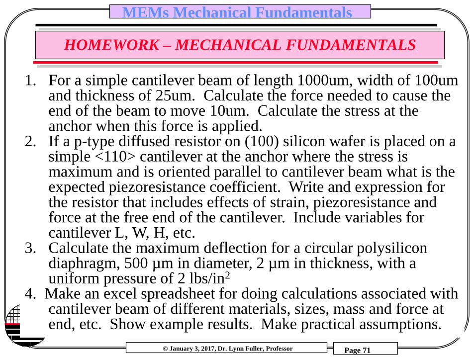
HOMEWORK – MECHANICAL FUNDAMENTALS
1. For a simple cantilever beam of length 1000um, width of 100um and thickness of 25um. Calculate the force needed to cause the end of the beam to move 10um. Calculate the stress at the anchor when this force is applied.
2. If a p-type diffused resistor on (100) silicon wafer is placed on a simple <110> cantilever at the anchor where the stress is maximum and is oriented parallel to cantilever beam what is the expected piezoresistance coefficient. Write and expression for the resistor that includes effects of strain, piezoresistance and force at the free end of the cantilever. Include variables for cantilever L, W, H, etc.
3. Calculate the maximum deflection for a circular polysilicon diaphragm, 500 µm in diameter, 2 µm in thickness, with a uniform pressure of 2 lbs/in2
4. Make an excel spreadsheet for doing calculations associated with cantilever beam of different materials, sizes, mass and force at end, etc. Show example results. Make practical assumptions.