memorial park - ministry for culture and heritage
TRANSCRIPT
SPECIFICATION of work to be done and materials to be used in carrying out the works shown on the accompanying drawings
National War Memorial Park
Wellington for
NZILA Specification prepared by
WALA
Rev: Date Comment
A 09.12.2013 DRAFT - 90% Documentation Issue
B 06.01.2014 100% Documentation Issue
C 10.01.2014 100% Documentation WCC Issue

© CIL Masterspec 2013 1012 TABLE OF CONTENTS Page 2
1012 TABLE OF CONTENTS 1012 TABLE OF CONTENTS ...................................................................................................... 2 2110 SALVAGE ........................................................................................................................... 3 3124 INSITU CONCRETE - FINISHES ....................................................................................... 5 3130 PRECAST CONCRETE - FINISHES ................................................................................ 14 3361 STONEWORK + BRICK FEATURES ............................................................................... 26 4924 LANDSCAPE METALWORK ............................................................................................ 30 6700R RESENE PAINTING GENERAL ....................................................................................... 45 6711R RESENE PAINTING EXTERIOR ...................................................................................... 58 8226 AGGREGRATE PAVING + FEATURE ROCKS ............................................................... 62 8231 CONCRETE UNIT PAVING .............................................................................................. 65 8310 LANDSCAPE SITE PREPARATION ................................................................................ 69 8321 SOIL AND SOIL PREPARATION FOR PLANTING ......................................................... 74 8332 PLANTING ........................................................................................................................ 84 8333 TURF LAYING ................................................................................................................ 100 8380 LANDSCAPE MAINTENANCE ....................................................................................... 104 8422 CARPENTRY .................................................................................................................. 118 8461 STREET FURNITURE .................................................................................................... 126 0000A SCHEDULES - DRAWING REGISTER .......................................................................... 134 0000B SCHEDULES – PLANT SCHEDULE .............................................................................. 136

© CIL Masterspec 2013 JUN 2110 SALVAGE Page 3
2110 SALVAGE 1. GENERAL This section relates to the salvage of existing materials only, 1.1 RELATED WORK Refer to 2110 for DEMOLITION WORKS (ENGINEERS SPECIFICATION) Refer to 2241 for EXCAVATION (ENGINEERS SPECIFICATION) 1.2 DOCUMENTS Documents referred to in this section are: NZBC F5/AS1 Construction and demolition hazards NZS 6803 Acoustics - Construction noise NZDAA Best practice guidelines for demolition in New Zealand NZDAA New Zealand guidelines for the management and removal of asbestos Health and Safety in Employment Act 1992 1.3 QUALIFICATION Carry out SALVAGE only under the supervision of a suitably experienced person and
using only experienced operators and drivers. Use only experienced, certified, construction blasters for explosives demolition.
1.4 SURVEY Before commencing work, carry out a thorough survey and examination of all structures
to be SALVAGED in order to ensure the extent, sequence, technique and method of demolition proposed can be safely and efficiently carried out.
Take photographs of the works, adjacent buildings and sites, before commencing work. Provide a set of these photographs as a record of existing condition.
1.5 ARCHAEOLOGICAL DISCOVERY If fossils, Maori artefacts, antiquities and other items of value are found refer to the
general section 1220 PROJECT for actions to be taken with archaeological discovery. 1.6 SALVAGE Designated items remain the property of the owner. 2. PRODUCTS 2.1 ELEMENTS FOR SALVAGE OR RE-USE Carefully dismantle, remove and store on site where directed. Protect from damage and
weather until required. 3. EXECUTION 3.1 SALVAGE Carefully dismantle and store safely all salvage items where directed; for removal, use on
the site, or until completion of the works. 3.2 REINSTATE AND MAKE GOOD Reinstate and make good demolition damage to adjoining properties, existing work,
services, or property. 3.3 TAKE AWAY Take away from the site all plant and equipment, temporary access works and
demolished materials and elements. Leave the site completely clean and tidy.

© CIL Masterspec 2013 JUN 2110 SALVAGE Page 4
4. SELECTIONS 4.1 ELEMENTS FOR SALVAGE AND DELIVERY TO OWNER Salvage the following elements and deliver to the owner. Refer to Engineers specification. 4.2 ELEMENTS FOR RE-USE Element/ component
Location Location for re-use
Glazed Brick kerbs
Entrance to Massey University
Tangata Whenua Gardens
S5 Concrete Seat
TBC by Principle Deliver to site Install as per contract Drawings
END OF SECTION
© CIL Masterspec 2013 MAR 3124 INSITU CONCRETE - FINISHES Page 5
3124 INSITU CONCRETE - FINISHES 1. GENERAL This section relates to the standard of concrete finishes, exposed aggregate surfaces,
floors and pavements, plain and textured. This include: - insitu concrete paving - Pi1 cast insitu flush concrete strip / historical interpretation 1.1 RELATED WORK Refer to 2110 SALVAGE for concrete wall
Refer to 3120 PRECAST CONCRETE - FINISHES for precast concrete Refer to 3361 STONEWORK + BRICK INSERT for stone and brick cladding Refer to 4924 LANDSCAPE METALWORK for metalwork Refer to 6711R RESENE PAINTING EXTERIOR for painting finishes Refer to 8231 CONCRETE UNIT PAVING for unit pavers and tactile pavers Refer to 8461 STREET FURNITURE for furniture Refer to 3101 for CONCRETE WORK - BASIC Refer to Engineers technical specification for concrete paving, kerbs, edge and dished channels.
Documents 1.2 DOCUMENTS Refer to the general section 1233 REFERENCED DOCUMENTS. The following
documents are specifically referred to in this section: NZBC D1/AS1 Access routes NZBC D1/VM1 Access routes NZS 3114 Specification for concrete surface finishes NZS 3121 Specification for water and aggregate for concrete AS/NZS 3661.1 Slip resistance of pedestrian surfaces - Requirements Requirements 1.3 QUALIFICATIONS Workers to be experienced, competent and familiar with the materials and techniques
specified. Carry out concrete works under the supervision of a suitably experienced person, using only operators and drivers trained for this work. Experienced personnel: The Contractor shall be required to nominate the operational personnel for these works having appropriate proven experience in this type of precast construction. Conformance to visual requirements: The Contractor shall conform to the requirements of the prototype, drawings and this Specification to achieve the quality and finish shown in the documentation. Unless otherwise qualified or amended by this section of the Specification or shown on the structural drawings all work covered by this section of the Specification shall be carried out in strict accordance with NZS 3109. The Contractor shall be familiar with these standards and have (at his own expense) access to the standards for reference at all times. Provide continuous supervision on site by a foreman experienced in this type of work.
1.4 SUBCONTRACTORS Submit name and contact details of proposed manufacturer of precast concrete units.

© CIL Masterspec 2013 MAR 3124 INSITU CONCRETE - FINISHES Page 6
1.5 RECORDS Record on site and make available to the Engineer records of the quantities of concrete,
cement and aggregate used on the various portions of the Contract. Supply the Engineer with dockets of certified plant mix showing the time of loading the mixer drums, the time of completion of unloading, mix type and the job.
1.6 WARRANTIES Obtain all warranties including (but not exclusive to)
Concrete sealant Concrete anti graffiti coating
1.7 PROVIDE SAMPLE PANEL Provide a sample panel of the following specified finishes before commencing work.
Panels to be of similar thickness to the proposed construction.
Conformance: Supply sample panels to AS 3610 and in conformance with the Sample panels schedule (below) for the application specified. Supply samples for concrete that include all saw cut or other jointing patterns and specified finishes as per design. Cast the sample panels using the formwork, concrete, compaction equipment, form release agents curing and removal methods which are to be used in the final work. Samples shall be made and kept in an area remote from the designated locations for the constructed concrete elements that are to be installed. Do not proceed with the related work until the acceptable range of surface treatments has been determined.
1.8 SAMPLE PANEL SCHEDULE (For precast samples refer to section 3130) code Panel / sample Incorporated features Panel Sizes SURFACING
CP1 In situ concrete paving (pedestrian loading)
Saw cut joint Concrete finish Colour and aggregate sample Radius edge
2 metres
CP2 In situ concrete paving (vehicular loading)
Saw cut joint Concrete finish Colour and aggregate sample Radius edge
2 metres
HERTIGATE
Pi1 In situ concrete flush strip
Saw cut joint Concrete finish Colour and aggregate sample Radius edge
2 metres
1.9 CAST SAMPLE PANELS For precast samples refer to section 3130 1.10 COLOUR VARIATION Keep inherent shade variations within the range of the grey scale in NZS 3114. Obtain
written instructions regarding the colour established in the sample reference panel for matching.
© CIL Masterspec 2013 MAR 3124 INSITU CONCRETE - FINISHES Page 7
1.11 TECHNIQUE DISCUSSION Before casting the sample panel arrange a meeting to confirm the method of preparing
the sample. After agreement that the sample panel is truly representative of the finish specified and can be produced on site, it then becomes the standard for that finish.
1.12 SAMPLE SLIP RESISTANCE Test sample to AS/NZS 3661.1 for slip resistance, to comply with NZBC D1/VM1 and
NZBC D1/AS1, 2.0, Level access routes; 3.14 Slip resistance for ramps and 4.14 Stair treads.
- When in place on a level access route, to have a mean coefficient of friction (µ) not less than 0.4.
- When in place on a sloping access route, to have a coefficient of friction (µ) not less than 0.4 + 0.0125S (S = slope of surface expressed as a percentage).
- When in place on stair treads, to NZBC D1/AS1, Table 2. Provide certificates and any other evidence that the surface complies with the standard of
performance specified. 1.13 RUN OFF Ensure run off acids, other chemicals and cement products are contained within the site.
They must not damage other surfaces, enter drains or pollute landscapes or water courses.
Performance 1.14 INSPECTIONS
Give notice so that inspection may be made of the following: Hold points
Concrete formwork and reinforcement in position Precast Moulds complete Trial set-outs before execution. Samples as per sample schedule
Witness points
Set out of joints Set out of service Pit lid covers Control joints before sealing and grouting Precast Moulds complete
2. PRODUCTS 2.1 MATERIALS
All materials shall conform to NZS 3109 except that additives shall not be used without the written consent of the Engineer, and when used shall be at the Contractor's expense.
2.2 CEMENT
Unless otherwise specified cement shall be Type GP, General Purpose Portland cement, complying with the requirements of NZS 3122. Cement in storage shall be kept dry and on a platform at least 225 mm above the ground. Cement which has become lumpy or partially set shall be condemned and removed from the works immediately. Cement shall be ordinary Portland cement complying with NZS 3122, so stored and handled as to be protected from moisture or any contamination. The Engineer may at any time require tests or analysis to be carried out in accordance with the Standards. Any cement not approved shall be removed from the site or from the place of manufacture.
2.3 CONCRETE COLOUR Proprietary natural oxides added to the concrete at mixing. Refer to SELECTIONS for
brand and colour. 2.4 AGGREGRATES

© CIL Masterspec 2013 MAR 3124 INSITU CONCRETE - FINISHES Page 8
River stone. Aggregates and their gradings shall comply with NZS 3121. The source of the aggregates shall be approved prior to commencement of manufacture and neither the source of the aggregate nor the grading shall be changed during the course of the contract without approval. When requested by the Engineer, the supplier shall submit the results of sieve analyses carried out by a laboratory qualified and equipped for such work. The use of pumps for concrete placement shall not constitute an acceptable justification for reduction in aggregate size.
2.4 WATER Water shall comply with NZS 3121 and shall be free from significant amounts of
deleterious impurities. 2.6 ADDITIVES Additives shall not be used without the written consent of the Engineer, and when used
shall be at the Contractor's expense. Approved admixtures shall comply with NZS 3113 and their use in concrete shall be in accordance with that code.
Admixtures shall not contain calcium chloride, nor shall they adversely affect the reinforcement or any protective coating thereon.
2.5 SEALERS Proprietary penetrating or surface sealers. Refer to SELECTIONS for brand and type. 3. EXECUTION Conditions 3.1 RESPONSIBILITY Take responsibility for determining the method of producing the specified finished
surface. 3.2 PROTECTION Protect and maintain the specified finish where necessary during any handling, erection
or subsequent construction operation to ensure a clean undamaged surface at completion of the contract works.
3.3 GENERAL Except where noted otherwise on the drawings or in the specification, tolerances in
regard to colour and surface to the requirements of NZS 3114 for each finish specified. 3.4 SURFACE TOLERANCES Variations from a plane surface are defined as follows: Abrupt: 2mm Steps or irregularities caused by displacement of form joints and
measured between peak and hollow over a 200mm straight edge. Gradual: 3mm Undulations over the surface and measured between rise and hollow
over a 1500mm straight edge.
Check all dimensions on the site and notify the Engineer of any inconsistencies of levels or dimensions with the plans prior to commencing work. In addition the required standard of the tolerance shall be such that all fittings, equipment, etc. can be installed accurately and neatly as required by the drawings and specification. It is particularly required that at construction joints that upward curl and or misalignment in level is prevented.
© CIL Masterspec 2013 MAR 3124 INSITU CONCRETE - FINISHES Page 9
All surfaces shall be finished in conformity with the lines, grades, thickness and cross sections shown on the drawings or specified within the following limits: Pavements shall be graded to achieve falls and levels indicated on the layout plans.
3.5 RISKS OF CRACKS FORMING Ensure substrate is free of cracks. Follow correct procedures for curing to minimise
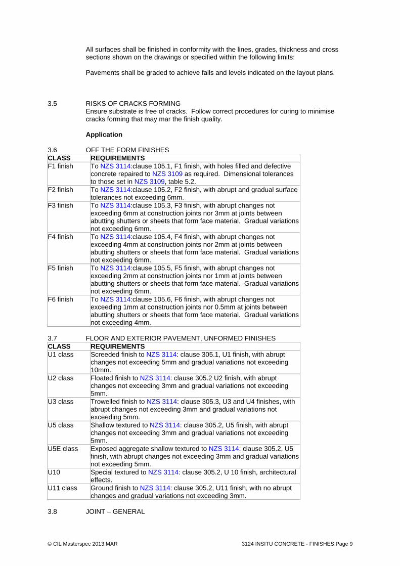
cracks forming that may mar the finish quality. Application 3.6 OFF THE FORM FINISHES CLASS REQUIREMENTS F1 finish To NZS 3114:clause 105.1, F1 finish, with holes filled and defective
concrete repaired to NZS 3109 as required. Dimensional tolerances to those set in NZS 3109, table 5.2.
F2 finish To NZS 3114:clause 105.2, F2 finish, with abrupt and gradual surface tolerances not exceeding 6mm.
F3 finish To NZS 3114:clause 105.3, F3 finish, with abrupt changes not exceeding 6mm at construction joints nor 3mm at joints between abutting shutters or sheets that form face material. Gradual variations not exceeding 6mm.
F4 finish To NZS 3114:clause 105.4, F4 finish, with abrupt changes not exceeding 4mm at construction joints nor 2mm at joints between abutting shutters or sheets that form face material. Gradual variations not exceeding 6mm.
F5 finish To NZS 3114:clause 105.5, F5 finish, with abrupt changes not exceeding 2mm at construction joints nor 1mm at joints between abutting shutters or sheets that form face material. Gradual variations not exceeding 6mm.
F6 finish To NZS 3114:clause 105.6, F6 finish, with abrupt changes not exceeding 1mm at construction joints nor 0.5mm at joints between abutting shutters or sheets that form face material. Gradual variations not exceeding 4mm.
3.7 FLOOR AND EXTERIOR PAVEMENT, UNFORMED FINISHES CLASS REQUIREMENTS U1 class Screeded finish to NZS 3114: clause 305.1, U1 finish, with abrupt
changes not exceeding 5mm and gradual variations not exceeding 10mm.
U2 class Floated finish to NZS 3114: clause 305.2 U2 finish, with abrupt changes not exceeding 3mm and gradual variations not exceeding 5mm.
U3 class Trowelled finish to NZS 3114: clause 305.3, U3 and U4 finishes, with abrupt changes not exceeding 3mm and gradual variations not exceeding 5mm.
U5 class Shallow textured to NZS 3114: clause 305.2, U5 finish, with abrupt changes not exceeding 3mm and gradual variations not exceeding 5mm.
U5E class Exposed aggregate shallow textured to NZS 3114: clause 305.2, U5 finish, with abrupt changes not exceeding 3mm and gradual variations not exceeding 5mm.
U10 Special textured to NZS 3114: clause 305.2, U 10 finish, architectural effects.
U11 class Ground finish to NZS 3114: clause 305.2, U11 finish, with no abrupt changes and gradual variations not exceeding 3mm.
3.8 JOINT – GENERAL

© CIL Masterspec 2013 MAR 3124 INSITU CONCRETE - FINISHES Page 10
Provide movement joints as shown on finishes drawing and set out plans Over structural (isolation, contraction, expansion) joints. At junctions between different substrates. To divide large paved areas into bays, maximum 6 m wide, maximum area
16 m2.
No joint shall be provided within 1m of the junction of any walls or edges unless directed otherwise within the drawing package.
3.9 EXPANSION JOINTS + CONSTRUCTION JOINTS
The concrete placing shall be carried out continuously between expansion joints and in such a manner that a plastic concrete face is maintained. Where the location of expansion joints are shown on the drawings, they shall neither be relocated nor eliminated without the approval of the Engineer. Where no expansion joints are shown on the Contract Drawings and such are required, their location shall be to the approval of the Engineer. Sealant Colour to match that of the concrete and required sample approval from Landscape Architect. Apply in accordance with manufacturer’s instructions.
3.10 SAW CUTS Saw cuts: - Dimensions as per drawing s - saw cuts to be left without grout
Sawcuts shall be made in a manner to prevent chipping of edges during the operation - generally between 24 and 36 hours after casting. Saw cuts shall be to the depths shown on the drawings and shall be made using a self propelled diamond tipped circular saw machine.
Finishing 3.11 RADIUS / CHAMFER WORK All edges will have no radius or chamfer to all visible sides unless stated otherwise in
drawings 3.12 GENERAL Achieve the standard of the specified finish required, direct from the formwork with a
minimum of attention to the stripped surface. 3.13 TIE HOLES Concealed tie holes unless agreed with Landscape Architect. If non concealed are
accepted fill tie holes to finish F5 and to colour match the parent concrete. 3.14 MINOR SURFACE DEFECTS Repair minor surface defects to match the shade and texture of the surrounding concrete. 3.15 PAINTED SURFACES Fill minor surface defects with approved plaster stopping compound/cellulose filler and
rub down to match the texture of the surrounding concrete. 3.16 SAND/ GRIT BLAST FINISH
Medium abrasive finish as described in CCANZ IB 18. After surface has matured and preferably within 7 days of the element reaching 28 day age, the surface identified to be sand blasted shall receive a uniform sand blast treatment. Abrasive blast the cured surface to provide an even texture without exposing the coarse aggregate using hard, sharp, graded abrasive particles. All sand blasting shall be undertaken by the same skilled sand blasting operator using the same equipment.
© CIL Masterspec 2013 MAR 3124 INSITU CONCRETE - FINISHES Page 11
The operator shall take care and provide such protection as is necessary to prevent sand blasting treatment of surfaces or planting adjacent. The texture of the final sand blast surface treatment to be approved by the Landscape Architect/Architect. Type of particle
Sand or high pressure water Provide light acid wash to clean the surface after sand blasting
Colour concrete 3.17 COLOUR CONCRETE - WET MIX Add coloured oxides to the concrete to the wet mix, to the manufacturer’s
recommendations. 3.18 COLOUR CONCRETE - AFTER PLACING Apply (as a dry shake) pigments or liquids to the wet surface after placing. Sealer 3.19 SEALER Apply selected sealer to the manufacturer’s recommendations. Ensure slip resistance is achieved as per building code requirements for public accessible
routes. Obtain warranty from installer.
3.20 ANTI GRAFITTI COATING Apply selected to the manufacturer’s recommendations.
Obtain warranty from installer.

© CIL Masterspec 2013 MAR 3124 INSITU CONCRETE - FINISHES Page 12
4. SELECTIONS 4.1 PROVIDE SAMPLE PANEL Refer to clause 1.5 above for sample panel requirements. 4.2 EXTERIOR INSITU PAVEMENT Paving (CP1 + CP2) Properties Property Surface finish to AS/NZS 3114 F5 X Class Formwork Fair face Primary finish Steel float Supplementary Finish - vertical face
Light sand blast
Supplementary Finish - horizontal face
Light sand blast
Slip resistance classification to AS/NZS 4586. V Slip resistance treatment Required Slip resistance tests Required Surface modifier None
Concrete colour & aggregate mixes Aggregate to make up the % of concrete volume as required to make up the required MPA and comply with NZS 3121.
Type Aggregate size
Aggregate Proportion
Concrete colour
River stone aggregate or similar approved to meet NZ 3121 (sample approval by LA required)
Refer Engineers Specification
100% of aggregate
CP1 Natural concrete colour unless otherwise noted on drawings CP2 Concrete to be coloured with black oxide to match Peter Fell colour 698 Sample required for approval

© CIL Masterspec 2013 MAR 3124 INSITU CONCRETE - FINISHES Page 13
4.3 EXTERIOR HISTORICAL REFERENCE / CONCRETE STRIP Special feature (Pi1) Properties Property Surface finish to AS/NZS 3114 F5 X Class Formwork Fair face Primary finish Steel float Supplementary Finish - vertical face
Light sand blast
Supplementary Finish - horizontal face
Light sand blast
Slip resistance classification to AS/NZS 4586. V Slip resistance treatment Required Slip resistance tests Required Surface modifier None
Concrete colour & aggregate mixes Aggregate to make up the % of concrete volume as required to make up the required MPA and comply with NZS 3121.
Type Aggregate size
Aggregate Proportion
Concrete colour
River stone aggregate or similar approved to meet NZ 3121 (sample approval by LA required)
Refer Engineers Specification
100% of aggregate
No colour oxide to be added Sample required for approval
4.4 STAIR NOSING
Location: As shown on contract drawings Manufacturer/type: Latham Asbra Titaze S Exterior heavy duty slip resistant trowel able resign safety tread Colour Black (standard) to concrete
4.5 CONCRETE SEALER
Location: CP1, CP2 in situ concrete paving Manufacturer/type: Penetrative matt finish sealer
eg. ’Crystal Seal’ by Nuplex or MIS Enviro Sealer or similar approved to protect the surface from future staining.
Note: The sealer is to be clear in colour and be a matt finish 4.6 ANTI GRAFITTI COATING Location: CW6 insitu concrete wall
Manufacturer/type: ‘PSS 20’ anti-graffiti by Equus, or ‘Guardian Graffiti Shield' by Graffiti solutions
Note: Clear matt Graffiti Resistant Finish
END OF SECTION

© CIL Masterspec 2013 JUL 3130 PRECAST CONCRETE - FINISHES Page 14
3130 PRECAST CONCRETE - FINISHES 1. GENERAL This section relates to the required performance and FINISHES of the precast panels for
external works. This includes:
Precast walls Precast stairs Precast kerbs (including channels, crossings and permeable kerbs)
1.1 RELATED WORK Refer to the appropriate concrete section for concrete requirements.
Refer to 2110 SALVAGE for concrete wall Refer to 3124 INSITU CONCRETE - FINISHES for insitu concrete Refer to 3361 STONEWORK + BRICK INSERT for stone and brick cladding Refer to 4924 LANDSCAPE METALWORK for metalwork Refer to 6711R RESENE PAINTING EXTERIOR for painting finishes Refer to 8231 CONCRETE UNIT PAVING for unit pavers and tactile pavers Refer to Engineers technical specification for concrete specification, concrete paving, kerbs and dished channels Refer to Engineers technical specification for UW underpass wall
1.2 DOCUMENTS Refer to the general section 1233 REFERENCED DOCUMENTS. The following
documents are specifically referred to in this section: NZBC D1/VM1 Access routes NZS 3104 Specification for concrete production NZS 3109 Concrete construction NZS 3112.1 Methods of test for concrete - Tests relating to fresh concrete NZS 3114 Specification for concrete surface finishes NZS 3121 Water and aggregate for concrete AS/NZS 3661.1 Slip resistance of pedestrian surfaces - Requirements AS/NZS 4671 Steel reinforcing materials AS/NZS ISO 9001 Quality management systems - Requirements Precast CoP Approved Code of Practice for Safe Handling, Transportation and
Erection of Precast Concrete (OSH) Requirements 1.3 PREPLANNING Prior to shop drawing/manufacture of the precast panels the Contractor, Precaster and
other relevant parties, must liaise, to ensure installation/on-site requirements are coordinated with the panel production.
1.4 SHOP DRAWINGS Refer to the general section 1235 SHOP DRAWINGS for the requirements for submission
and review and the provision of final shop drawings. Provide shop drawings to show the general arrangement including, but not be limited to:
size, spacing and cover of reinforcement details, position and layout of cast in items, including those for, lifting,
handling, fastening and connecting details of panel edges surface finish requirements and locations location and size of rebates, recesses and penetrations grout ducts concrete mix requirements and strength concrete volume and weight of finished unit for lifting

© CIL Masterspec 2013 JUL 3130 PRECAST CONCRETE - FINISHES Page 15
for insulated panels, details of insulation, low conduction connectors/ties, vapour barrier
Submit shop drawings for review to ~.
5working days (at least) before fabrication is planned to commence, provide shop drawings for review.
Do not commence fabrication of any panel before shop drawing review of the panel is complete.
Shop drawing review (and subsequent fabrication) can be carried out on an agreed sectional/staged basis.
Shop Drawing schedule
Code Type Comment WALLS
PCW# precast concrete walls Provide shop drawing
STAIRS
PSS# precast stair – stone clad Provide shop drawing
PSC# precast stair - concrete Provide shop drawing
KERBS
KCP Permeable kerbs Provide shop drawing
KCF Flush kerbs Provide shop drawing
KC Upstand kerbs Provide shop drawing
KCo Upstand kerbs with channel Provide shop drawing
KCdc Dish Channel Provide shop drawing
KXc Kerb crossing (pedestrian) Provide shop drawing
KXcv Kerb crossing (vehicular) Provide shop drawing
KCW WCC kerb + channel Provide shop drawing
1.5 MANUFACTURERS STATEMENT OF COMPLIANCE Provide a Manufacturer's Statement of Compliance from the Precast CoP. 1.6 PANEL SURFACE Use appropriate mould materials, moulding systems and casting methods to achieve the
specified surface finishes. Refer to SELECTIONS for surface finishes. 1.7 SAMPLE
Conformance: Supply sample panels to AS 3610 and in conformance with the Sample panel’s schedule (below) for the application specified. Supply samples for pre-cast concrete that include all saw cut or other jointing patterns and specified finishes as per design. Cast the sample panels using the formwork, concrete, compaction equipment, form release agents curing and formwork removal methods which are to be used in the final work. Samples shall be made and kept in an area remote from the designated locations for the constructed concrete elements that are to be installed. Do not proceed with the related work until the acceptable range of surface treatments has been determined. Allow 2 weeks for review. Sample schedule
Code Type Associated features Sample required
© CIL Masterspec 2013 JUL 3130 PRECAST CONCRETE - FINISHES Page 16
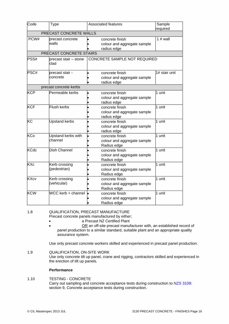
Code Type Associated features Sample required
PRECAST CONCRETE WALLS
PCW# precast concrete walls
concrete finish colour and aggregate sample radius edge
1 # wall
PRECAST CONCRETE STAIRS
PSS# precast stair – stone clad
CONCRETE SAMPLE NOT REQUIRED
PSC# precast stair - concrete
concrete finish colour and aggregate sample radius edge
1# stair unit
precast concrete kerbs
KCP Permeable kerbs concrete finish colour and aggregate sample radius edge
1 unit
KCF Flush kerbs concrete finish colour and aggregate sample radius edge
1 unit
KC Upstand kerbs concrete finish colour and aggregate sample radius edge
1 unit
KCo Upstand kerbs with channel
concrete finish colour and aggregate sample Radius edge
1 unit
KCdc Dish Channel concrete finish colour and aggregate sample Radius edge
1 unit
KXc Kerb crossing (pedestrian)
concrete finish colour and aggregate sample Radius edge
1 unit
KXcv Kerb crossing (vehicular)
concrete finish colour and aggregate sample Radius edge
1 unit
KCW WCC kerb + channel concrete finish colour and aggregate sample Radius edge
1 unit
1.8 QUALIFICATION, PRECAST MANUFACTURE Precast concrete panels manufactured by either;
a Precast NZ Certified Plant OR an off-site precast manufacturer with, an established record of
panel production to a similar standard, suitable plant and an appropriate quality assurance system.
Use only precast concrete workers skilled and experienced in precast panel production. 1.9 QUALIFICATION, ON-SITE WORK Use only concrete tilt up panel, crane and rigging, contractors skilled and experienced in
the erection of tilt up panels. Performance 1.10 TESTING - CONCRETE Carry out sampling and concrete acceptance tests during construction to NZS 3109:
section 9, Concrete acceptance tests during construction.
© CIL Masterspec 2013 JUL 3130 PRECAST CONCRETE - FINISHES Page 17
Conduct 7 day strength tests. After a 7 day test result of less than 60% of the specified strength, concrete placement to stop until it is shown the suspect concrete complies with the specification.
Carry out slump tests, yield tests and air content tests to NZS 3112.1, sections 4, 5 and 9,
and evaluate to NZS 3104.2.15. Control tests and their evaluation. Make available all test records to the contract administrator on request.
1.11 CONFIRM STEEL REINFORCING COMPLIANCE Provide written confirmation that the steel reinforcing supplied complies with the grades
specified on the drawings, by producing test results to AS/NZS 4671 1.12 QUALITY ASSURANCE Carry out the whole of this work to the requirements of NZS 3109 and under the regime of
a quality system for quality assurance in production and erection. Advise name of the suitably experienced and qualified representative who is responsible
for quality control of the concrete work. The representative is to sign a written quality control checklist for each concrete pour.
1.13 INSPECTION NOTIFICATION REQUIREMENTS
Give notice so that inspection may be made of the following: Hold points
Concrete formwork and reinforcement in position Precast Moulds complete Samples as per sample schedule
Witness points
Precast Moulds complete 1.14 SAMPLE SLIP RESISTANCE FOR KERBS Test sample to AS/NZS 3661.1 for slip resistance, to comply with NZBC D1/VM1. - When in place on a level access route, to have a mean coefficient of friction (& micro)
not less than 0.4. - When in place on a sloping access route, to have a coefficient of friction (& micro) not
less than 0.4 + 0.0125S (S = slope of surface expressed as a percentage). Provide certificates and any other evidence that the surface complies with the standard of
performance specified. 1.15 SITE LOADINGS, PERMANENT STRUCTURE Prevent damage to supporting structure from stacking of precast items. 2. PRODUCTS 2.1 MATERIALS
All materials shall conform to NZS 3109 except that additives shall not be used without the written consent of the Engineer, and when used shall be at the Contractor's expense.
2.2 CONCRETE To NZS 3104. Refer to CONCRETE section for concrete supply and to SELECTIONS for concrete
strength. 2.3 CONCRETE COLOUR Proprietary natural oxides added to the concrete at mixing. Refer to SELECTIONS for
brand and colour. 2.4 AGGREGRATES
Aggregates and their gradings shall comply with NZS 3121.

© CIL Masterspec 2013 JUL 3130 PRECAST CONCRETE - FINISHES Page 18
The source of the aggregates shall be approved prior to commencement of manufacture and neither the source of the aggregate nor the grading shall be changed during the course of the contract without approval. When requested by the Engineer, the supplier shall submit the results of sieve analyses carried out by a laboratory qualified and equipped for such work. The use of pumps for concrete placement shall not constitute an acceptable justification for reduction in aggregate size.
2.4 GRADE 300E STEEL To AS/NZS 4671. Round bars are shown by symbol "R" and deformed bars by symbol
"D", followed by the diameter in millimetres. 2.5 GRADE 500E STEEL To AS/NZS 4671. Round bars shown by symbol "HR" and deformed bars by symbol
"HD" followed by diameter in millimetres. 2.6 WELDED WIRE FABRIC Hard drawn steel wire spot welded with correct gauge to AS/NZS 4671, smooth or
deformed and to the spacing and dimensions either specified or shown on the drawings. 2.7 SPACERS AND CHAIRS Precast concrete or purpose made moulded PVC to approval. Where concrete spacer
blocks are used in exposed concrete work use blocks matching surrounding concrete. 2.8 SEALAERS + ANIT GRAFITTI COATINGS Proprietary penetrating or surface sealers. Refer to SELECTIONS for brand and type. Components 2.9 LIFTING INSERTS Proprietary lifting inserts to the Precast CoP, minimum finish galvanised mild steel. 2.10 CAST IN STEEL ITEMS Cast in items as detailed and required. Ensure items are prefinished where required. 2.11 LEVELLING SHIMS Rigid plastic or other suitable levelling shims to Precast CoP. 2.12 SEALANTS Polysulphide, polyurethane or silicone gap filling proprietary sealants. 3. EXECUTION Conditions 3.1 HANDLE, TRANSPORT AND STACK Handle, transport and stack panels to ensure support that avoids distortion and stress
and at the same time protects the finished surfaces from chipping, scoring, cracking or other disfigurement. Storage methods and packing between panels should minimise colour variations to exposed surfaces.
Arrange delivery and erection of precast panels to minimise handling, storage or restacking on site.
Manufacture 3.2 TOLERANCES, OFF-SITE PRECAST, CRITICAL Manufacture panels to the following tolerances: Item Tolerance
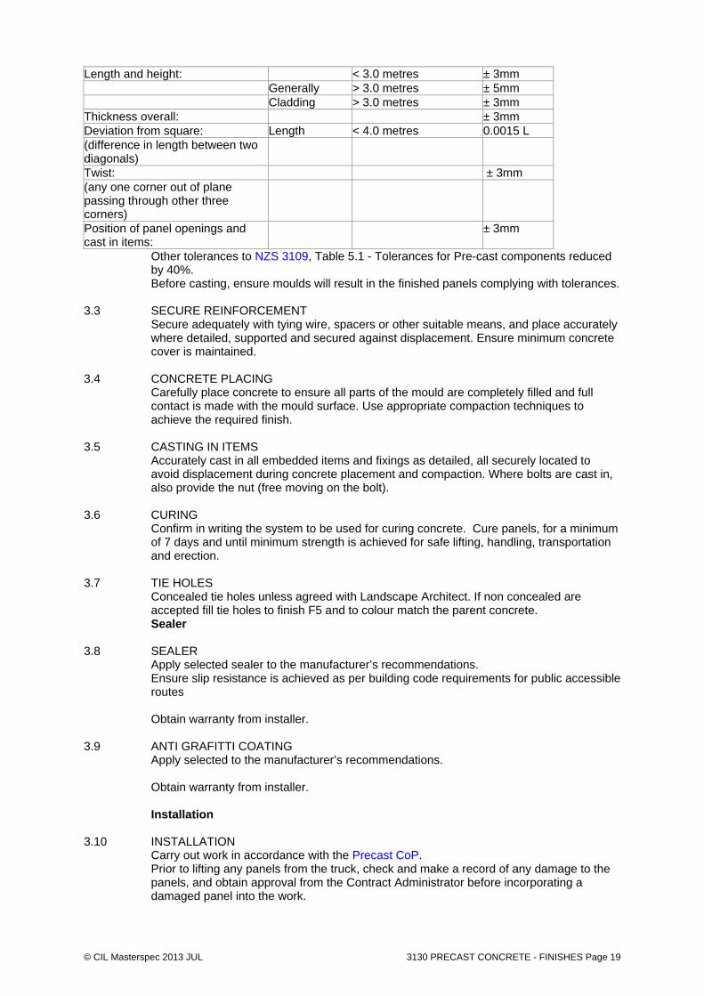
© CIL Masterspec 2013 JUL 3130 PRECAST CONCRETE - FINISHES Page 19
Length and height: < 3.0 metres ± 3mm Generally > 3.0 metres ± 5mm Cladding > 3.0 metres ± 3mm Thickness overall: ± 3mm Deviation from square: Length < 4.0 metres 0.0015 L (difference in length between two diagonals)
Twist: ± 3mm (any one corner out of plane passing through other three corners)
Position of panel openings and cast in items:
± 3mm
Other tolerances to NZS 3109, Table 5.1 - Tolerances for Pre-cast components reduced by 40%.
Before casting, ensure moulds will result in the finished panels complying with tolerances. 3.3 SECURE REINFORCEMENT Secure adequately with tying wire, spacers or other suitable means, and place accurately
where detailed, supported and secured against displacement. Ensure minimum concrete cover is maintained.
3.4 CONCRETE PLACING Carefully place concrete to ensure all parts of the mould are completely filled and full
contact is made with the mould surface. Use appropriate compaction techniques to achieve the required finish.
3.5 CASTING IN ITEMS Accurately cast in all embedded items and fixings as detailed, all securely located to
avoid displacement during concrete placement and compaction. Where bolts are cast in, also provide the nut (free moving on the bolt).
3.6 CURING Confirm in writing the system to be used for curing concrete. Cure panels, for a minimum
of 7 days and until minimum strength is achieved for safe lifting, handling, transportation and erection.
3.7 TIE HOLES Concealed tie holes unless agreed with Landscape Architect. If non concealed are
accepted fill tie holes to finish F5 and to colour match the parent concrete. Sealer 3.8 SEALER Apply selected sealer to the manufacturer’s recommendations. Ensure slip resistance is achieved as per building code requirements for public accessible
routes Obtain warranty from installer.
3.9 ANTI GRAFITTI COATING Apply selected to the manufacturer’s recommendations.
Obtain warranty from installer. Installation 3.10 INSTALLATION Carry out work in accordance with the Precast CoP. Prior to lifting any panels from the truck, check and make a record of any damage to the
panels, and obtain approval from the Contract Administrator before incorporating a damaged panel into the work.
© CIL Masterspec 2013 JUL 3130 PRECAST CONCRETE - FINISHES Page 20
3.11 SETTING OUT Confirm panel dimensions, set out and site conditions. Also check starter bars, grout
tube positions and fixing points. Check all temporary support work is ready, correct and capable of taking imposed loads.
3.12 TOLERANCES, ON - SITE EXECUTION Locate precast items to the following tolerances: Plan: ± 10mm Vertical: ± 1mm/metre Panel Joint width: ± 1mm/metre; but no panel joint shall be less than 10mm, or more
than 20mm (unless indicated otherwise on drawings) 3.13 LIFTING Mobile crane positions to be arranged and prepared prior to panel delivery to provide safe
lifting. Ensure that all cranes can provide safe and easy movement of panels, as well as careful positioning. Check that rigging, straps, etc, suit the panel design and lifting points. Panels are to remain attached to the crane until they are either fully fixed into their final position or adequately secured by temporary means.
3.14 PROPPING AND BRACING Provide temporary adjustable props or braces to secure the panel in position until final
support is provided. They must be able to withstand the expected wind loads on the panel for the site and position.
3.15 PLACING On positioning of the panel, check that all reinforcing and fixings line up with the
appropriate items on the preceding work. Also check fixings will function as intended, in particularly fixings required to accommodate seismic movement. Ensure that there is no damage caused to the panel, surrounding surfaces or fixings during placing.
3.16 FINAL POSITION Adjust panels into final position, check alignment, verticality, joint widths etc., and fix into
place. 3.17 GROUT DUCTS Fill grout ducts with expansive grout, ensure ducts are completely filled. 3.18 POST PLACING ADJUSTMENTS After permanent placing check and adjust as necessary; - All fixings for correct alignment and operation, and check the torque on all nuts and
bolts - not less than 1 day after final fixing. - Recheck that all props, braces and fastenings are secure and capable of performing as
required - not less than 1 day and not more than 7 days after a panel is fixed into position and held by temporary means.
- If panels are subject to, high wind loads, unintended or accidental loads during construction, recheck props braces and fastenings.
3.19 SEALANTS Ensure at time of erection, that the limits of acceptable joint variation (from the
manufacturer's requirements) for each product are maintained. Prepare joints, protect adjoining surfaces, seal joint surfaces, fit limiting rods and insert sealant to the manufacturer's requirements and temperature limits.
3.20 CLEAN AND DRESS Clean and dress panels externally and internally to leave them to the standard of finish
specified and without blemish, ensuring following work can be completed to the required standard.
3.21 CLEAN UP Clean up surrounding areas of trade waste and remove temporary works required for the
installation of the precast concrete items.

© CIL Masterspec 2013 JUL 3130 PRECAST CONCRETE - FINISHES Page 21
3.22 REMOVE Remove debris, unused materials and elements from the site. 4. SELECTIONS 4.1 SAMPLE PANELS Refer to Requirements above 4.2 EXTERIOR PRECAST WALLS Walls (PCw) Properties Property Surface finish to AS/NZS 3114 F5 X Class Formwork Fairface Primary finish Steel float Supplementary Finish - vertical face
Light sand blast
Supplementary Finish - horizontal face
Light sand blast
Slip resistance classification to AS/NZS 4586. V Slip resistance treatment Required Slip resistance tests Required Surface modifier None Bolt hole filling Refer to clause above
Concrete colour & aggregate mixes Aggregate to make up the % of concrete volume as required making up the required MPA and complying with NZS 3121.
Type Aggregate size
Aggregate Proportion
Concrete colour
River stone aggregate or similar approved to meet NZ 3121 (sample approval by LA required)
Refer Engineers Specification
100% of aggregate
Concrete to be coloured with black oxide to match Peter Fell colour 698 Sample required for approval

© CIL Masterspec 2013 JUL 3130 PRECAST CONCRETE - FINISHES Page 22
4.3 EXTERIOR PRECAST CONCRETE STAIRS Stairs (PSs#) – stone clad Properties Property Surface finish to AS/NZS 3114 F3 Class Formwork Fairface Primary finish Steel float Supplementary Finish - vertical face
Light sand blast
Supplementary Finish - horizontal face
Light sand blast
Slip resistance classification to AS/NZS 4586. V Slip resistance treatment Required Slip resistance tests None Surface modifier None Bolt hole filling Refer to clause above
Concrete colour & aggregate mixes Aggregate to make up the % of concrete volume as required to make up the required MPA and comply with NZS 3121.
Type Aggregate size
Aggregate Proportion
Concrete colour
River stone aggregate or similar approved to meet NZ 3121 (sample approval by LA required)
Refer Engineers Specification
100% of aggregate
Concrete to be coloured with black oxide to match PeterFell colour 698. Sample required for approval
© CIL Masterspec 2013 JUL 3130 PRECAST CONCRETE - FINISHES Page 23
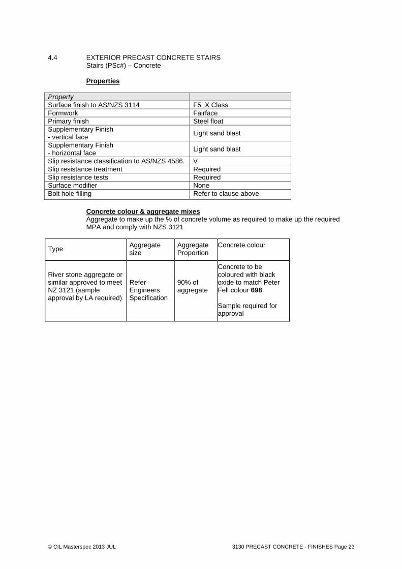
4.4 EXTERIOR PRECAST CONCRETE STAIRS Stairs (PSc#) – Concrete Properties Property Surface finish to AS/NZS 3114 F5 X Class Formwork Fairface Primary finish Steel float Supplementary Finish - vertical face
Light sand blast
Supplementary Finish - horizontal face
Light sand blast
Slip resistance classification to AS/NZS 4586. V Slip resistance treatment Required Slip resistance tests Required Surface modifier None Bolt hole filling Refer to clause above
Concrete colour & aggregate mixes Aggregate to make up the % of concrete volume as required to make up the required MPA and comply with NZS 3121
Type Aggregate size
Aggregate Proportion
Concrete colour
River stone aggregate or similar approved to meet NZ 3121 (sample approval by LA required)
Refer Engineers Specification
90% of aggregate
Concrete to be coloured with black oxide to match Peter Fell colour 698. Sample required for approval

© CIL Masterspec 2013 JUL 3130 PRECAST CONCRETE - FINISHES Page 24
4.5 EXTERIOR PRECAST CONCRETE KERBS All Kerbs Properties Property Surface finish to AS/NZS 3114 F5 X Class Formwork Fairface Primary finish Steel float Supplementary Finish - vertical face
Light sand blast
Supplementary Finish - horizontal face
Light sand blast
Slip resistance classification to AS/NZS 4586. V Slip resistance treatment Required Slip resistance tests Required Surface modifier None Bolt hole filling Refer to clause above
Concrete colour & aggregate mixes Aggregate to make up the % of concrete volume as required to make up the required MPA and comply with NZS 3121.
Type Aggregate size
Aggregate Proportion
Concrete colour
River stone aggregate or similar approved to meet NZ 3121 (sample approval by LA required)
Refer Engineers Specification
100% of aggregate
Concrete to be coloured with black oxide to match Peter Fell colour 698. Sample required for approval
4.6 STAIR NOSING Location: As shown on contract drawings Refer to MP-11-90442 “Stair Details 10” Manufacturer/type: Latham Asbra Titaze S Exterior heavy duty slip resistant trowel able resign safety tread Colour Black (standard) to concrete
4.7 SEALER Location: PSc# precast concrete stairs Manufacturer/type: Penetrative matt finish sealer
eg. ’Crystal Seal’ by Nuplex or MIS Enviro Sealer or similar approved to protect the surface from future staining.
Note: The sealer is to be clear in colour and be a matt finish 4.8 ANTI GRAFITTI COATING Location: All concrete walls
Manufacturer/type: ‘PSS 20’ anti-graffiti by Equus, or ‘Guardian Graffiti Shield' by Graffiti solutions
Note: Clear matt Graffiti Resistant Finish
END OF SECTION

© CIL Masterspec 2013 JUL 3130 PRECAST CONCRETE - FINISHES Page 25

© CIL Masterspec 2013 3361 STONEWORK + BRICK FEATURES Page 26
3361 STONEWORK + BRICK FEATURES 1. GENERAL This section relates to the supply, laying and fixing of non-load bearing stone, fixed to a
rigid structural backing or erected as a freestanding low wall. This includes:
500mm high stone kerb. Historic (Prisoner) bricks inserts to walls..
1.1 RELATED WORK
Refer to 2110 SALVAGE for Brick pavers Refer to 3124 INSITU CONCRETE - FINISHES for insitu concrete Refer to 3120 PRECAST CONCRETE - FINISHES for precast concrete Refer to 3361 STONEWORK + BRICK INSERT for stone and brick cladding Refer to 4924 LANDSCAPE METALWORK for metalwork Refer to 6711R RESENE PAINTING EXTERIOR for painting finishes Refer to 8226 GRAVEL PAVING for limechip surfacing Refer to 8231 CONCRETE UNIT PAVING for unit pavers and tactile pavers Refer to Engineers technical specification for Stone paving and setts, bedding and stone laying for salvaged glazed bricks for stair stone cladding
For stone finishes, refer to paving plans MP-11-90310, 90311 + 90312 “Detailed paving plans 1-3”
Documents 1.2 DOCUMENTS Refer to the general section 1233 REFERENCED DOCUMENTS. The following
documents are specifically referred to in this section: AS/NZS 2699.1 Built in components for masonry construction - Wall ties NZS 3103 Sands for mortars and plasters NZS 4210 Masonry construction: materials and workmanship Documents listed above and cited in the clauses that follow are part of this specification.
However, this specification takes precedence in the event of it being at variance with the cited document.
1.3 MANUFACTURER/SUPPLIER DOCUMENTS Manufacturer's and supplier's documents relating to this part of the work:
Contractor to source and refer to suppliers documentation Requirements 1.4 QUALIFICATIONS Stonemasons to be experienced competent workers, familiar with the materials and the
techniques specified. 1.5 SHOP DRAWINGS Provide shop drawings of set-out of blocks or panels complete with method of bedding
and fixing.
Allow 2 weeks for review. Shop drawing schedule
Item Shop drawings
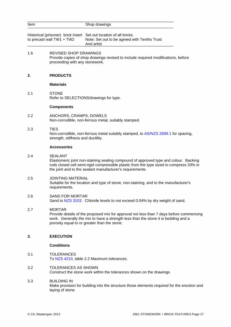
© CIL Masterspec 2013 3361 STONEWORK + BRICK FEATURES Page 27
Item Shop drawings
Historical (prisoner) brick insert to precast wall TW1 + TW2
Set out location of all bricks. Note: Set out to be agreed with Tenths Trust And artist
1.6 REVISED SHOP DRAWINGS Provide copies of shop drawings revised to include required modifications, before
proceeding with any stonework. 2. PRODUCTS Materials 2.1 STONE Refer to SELECTIONS/drawings for type. Components 2.2 ANCHORS, CRAMPS, DOWELS Non-corrodible, non-ferrous metal, suitably stamped. 2.3 TIES Non-corrodible, non-ferrous metal suitably stamped, to AS/NZS 2699.1 for spacing,
strength, stiffness and ductility. Accessories 2.4 SEALANT Elastomeric joint non-staining sealing compound of approved type and colour. Backing
rods closed cell semi-rigid compressible plastic from the type sized to compress 33% in the joint and to the sealant manufacturer's requirements.
2.5 JOINTING MATERIAL Suitable for the location and type of stone, non-staining, and to the manufacturer's
requirements. 2.6 SAND FOR MORTAR Sand to NZS 3103. Chloride levels to not exceed 0.04% by dry weight of sand. 2.7 MORTAR Provide details of the proposed mix for approval not less than 7 days before commencing
work. Generally the mix to have a strength less than the stone it is bedding and a porosity equal to or greater than the stone.
3. EXECUTION Conditions 3.1 TOLERANCES To NZS 4210, table 2.2 Maximum tolerances. 3.2 TOLERANCES AS SHOWN Construct the stone work within the tolerances shown on the drawings. 3.3 BUILDING IN Make provision for building into the structure those elements required for the erection and
laying of stone.

© CIL Masterspec 2013 3361 STONEWORK + BRICK FEATURES Page 28
3.4 BUILT IN ITEMS Make provision as the work proceeds for elements that need to be built in or keyed to the
stone work, including partitions, straps, handrails, beams, trusses and plates. 3.5 SUBSTRATE WATERPROOFING Check substrate waterproofing is suitable, complete and undamaged before commencing
stonework. 3.6 TRANSPORT Transport, unload and handle all stone units to avoid any damage or disfigurement.
Stack carefully in the vehicle with packing material to prevent damage. 3.7 STORE Store stone clear of the ground on its natural bed, protected from the weather and
atmospheric pollution on supports that avoid local overstressing and to promote good seasoning without staining, contamination, marking or damage.
Application 3.8 CUTTING Cut and shape stone to profiles generally as detailed and including all weathering,
jointing, chasing, forming mortises, grooves and drilling for handling and fixing. Work the bed, face and back joints of the stone square and true.
Application - facing work 3.9 SOLID BEDDING Adequately support and restrain cladding with durable fixings and continually and solidly
fill between backs and supporting structure with mortar. 3.10 SPOT BEDDING Adequately support and restrain cladding with durable fixings and provide mortar bedding
continuously around fixings and in the form of mortar dabs elsewhere. 3.11 JOINTING Prime surfaces in contact, fit backing rods to ensure correct depths of jointing material
and/or sealant, keeping panel surfaces completely clear and unmarked by masking, all to the jointing manufacturer's requirements.
Application - walling work 3.12 BED AND JOINT Bed and joint stone where possible in one operation on a full bed of mortar. Solidly fill
and grout vertical joints, joggles, cramps and the like as the work proceeds and point up joints around flashings.
3.13 SET STONE Set stone on its natural bed. 3.14 BEDDING SEDIMENTARY STONE Clean the bed area of dust and impurities and thoroughly damp it down before laying the
mortar bed. 3.15 RACKING Raise advanced work no more than 1m above the general level and rack back. Do not
tooth stonework unless shown on the drawings or when approved in writing. 3.16 SUPPORT Provide support to the stone while mortar cures by bracing or joint spacers of non-
staining softwood. When curing is complete remove spacers without damage to the stonework and point to match.
Finishing
© CIL Masterspec 2013 3361 STONEWORK + BRICK FEATURES Page 29
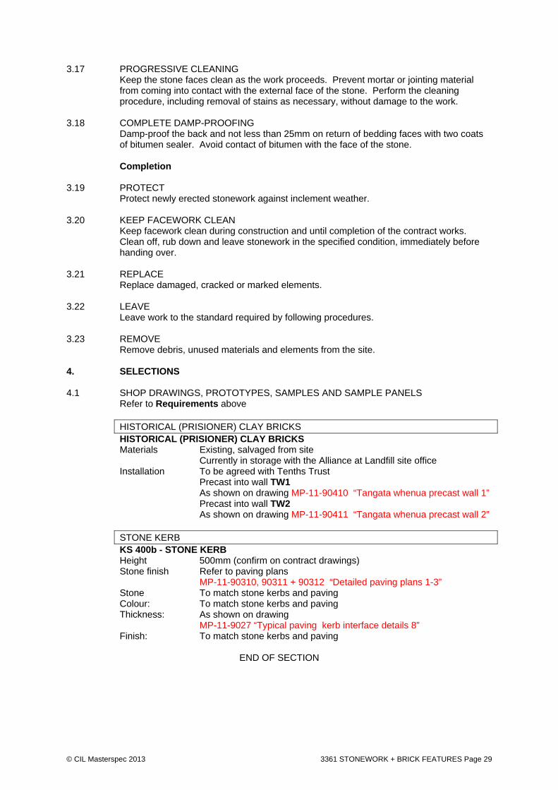
3.17 PROGRESSIVE CLEANING Keep the stone faces clean as the work proceeds. Prevent mortar or jointing material
from coming into contact with the external face of the stone. Perform the cleaning procedure, including removal of stains as necessary, without damage to the work.
3.18 COMPLETE DAMP-PROOFING Damp-proof the back and not less than 25mm on return of bedding faces with two coats
of bitumen sealer. Avoid contact of bitumen with the face of the stone. Completion 3.19 PROTECT Protect newly erected stonework against inclement weather. 3.20 KEEP FACEWORK CLEAN Keep facework clean during construction and until completion of the contract works.
Clean off, rub down and leave stonework in the specified condition, immediately before handing over.
3.21 REPLACE Replace damaged, cracked or marked elements. 3.22 LEAVE Leave work to the standard required by following procedures. 3.23 REMOVE Remove debris, unused materials and elements from the site. 4. SELECTIONS 4.1 SHOP DRAWINGS, PROTOTYPES, SAMPLES AND SAMPLE PANELS Refer to Requirements above
HISTORICAL (PRISIONER) CLAY BRICKS HISTORICAL (PRISIONER) CLAY BRICKS Materials Existing, salvaged from site Currently in storage with the Alliance at Landfill site office Installation To be agreed with Tenths Trust Precast into wall TW1 As shown on drawing MP-11-90410 “Tangata whenua precast wall 1” Precast into wall TW2 As shown on drawing MP-11-90411 “Tangata whenua precast wall 2”
STONE KERB KS 400b - STONE KERB Height 500mm (confirm on contract drawings) Stone finish Refer to paving plans MP-11-90310, 90311 + 90312 “Detailed paving plans 1-3” Stone To match stone kerbs and paving Colour: To match stone kerbs and paving Thickness: As shown on drawing MP-11-9027 “Typical paving kerb interface details 8” Finish: To match stone kerbs and paving
END OF SECTION

© CIL Masterspec 2013 DEC 4924 LANDSCAPE METALWORK Page 30
4924 LANDSCAPE METALWORK 1. GENERAL This section relates to the fabrication and installation of metal (steel, stainless steel and
aluminium) items used in exterior applications. This includes:
Light poles Signs Handrails Balustrades Boundary wall fence (to Mount cook school) QR code Pavilion structure
Also Metal frames for seats Metal support to timber decks
1.1 RELATED WORK Refer 8331 PLANTING for GBss Stainless steel garden edge restraint and for TRss Stainless steel tree pit edge restraint and for Kcss Stainless steel edge restraint
Refer to Engineers technical specification for structural metalwork. Refer to Engineers technical specification for SS grated drains Also: Refer to 3124 INSITU CONCRETE - FINISHES for insitu concrete Refer to 3120 PRECAST CONCRETE - FINISHES for precast concrete Refer to 6711R RESENE PAINTING EXTERIOR for painting finishes Refer to 8422 CARPENTRY for timbers Refer to 8461 STREET FURNITURE for furniture
Documents 1.2 DOCUMENTS Refer to the general section 1233 REFERENCED DOCUMENTS. The following
documents are specifically referred to in this section: Metalwork generally AS 1397 Continuous hot-dip metallic coated steel sheet and strip - Coatings of
zinc and zinc alloyed with aluminium and magnesium AS/NZS 1554.1 Structural steel welding - Welding of steel structures AS 1594 Hot-rolled steel flat products AS 1627.4 Metal finishing - Preparation and pretreatment of surfaces - Method
selection guide - Abrasive blast cleaning AS 1627.9 Metal finishing - Preparation and pretreatment of surfaces - Method
selection guide - Pictorial surface preparation standards for painting steel surfaces
AS/NZS 4680 Hot-dip galvanized (zinc) coatings on fabricated ferrous articles AS/NZS 4792 Hot-dip galvanized (zinc) coatings on ferrous hollow sections, applied
by a continuous or special process NZS/BS 1387 Screwed and socketed steel tubes and tubulars and for plain end steel
tubes suitable for welding or for screwing to BS 21 pipe threads NZS/BS 4848.2 Hot-rolled structural steel sections - Hollow sections NZS/BS 4848.4 Hot-rolled structural steel sections - Equal and unequal angles BS 4-1 Structural steel sections - Hot-rolled sections BS 2630 Resistance projection welding of uncoated low carbon steel sheet and
strip using embossed projections

© CIL Masterspec 2013 DEC 4924 LANDSCAPE METALWORK Page 31
BS 6265 Resistance seam welding of uncoated and coated low carbon steel BS 6497 Powder organic coatings for application and stoving to hot-dip
galvanized hot-rolled steel sections and pre-formed steel sheet BRANZ BU 467 Principles of flashing design Stainless steel specifically NZBC F4/AS1. Safety from falling AS/NZS 1554.6 Structural steel welding - Welding stainless steel for structural
purposes AS/NZS 4673 Cold-formed stainless steel structures ASTM A240 Standard specification for chromium and chromium-nickel stainless
steel plate, sheet and strip for pressure vessels and for general applications
ASTM A276 Standard specification for stainless steel bars and shapes ASTM A480 Standard specification for general requirements for flat-rolled stainless
steel and heat-resisting steel plate, sheet and strip ASTM A1016 Standard specification for general requirements for ferritic alloy steel,
austenitic alloy steel, and stainless steel tubes BS EN 1011-3 Welding. Recommendations for welding of metallic materials. Arc
welding of stainless steels BRANZ BU 467 Principles of flashing design Aluminium specifically AS/NZS 1734 Aluminium and aluminium alloys - flat sheets, coiled sheet and plate BRANZ BU 467 Principles of flashing design Cast bronze specifically AS 1566 Copper and copper alloys - Rolled flat products AS/NZS 1567 Copper and copper alloys - Wrought rods, bars and sections AS 1572 Copper and copper alloys - Seamless tubes for engineering purposes BRANZ BU 467 Principles of flashing design 1.3 MANUFACTURER/SUPPLIER DOCUMENTS Manufacturer's and supplier's documents relating to this part of the work:
Contractor to source and refer to suppliers documentation Requirements 1.4 QUALIFICATIONS Metalworkers to be experienced, competent trades people familiar with the materials and
techniques specified. 1.5 SUPPLIERS
Statements: Submit statements from suppliers of all metalwork, giving the following, where applicable;
Particulars of the supplier’s experience in the required type of work. Production capacity for material of the required type, sizes and
quantity. Lead times for delivery of the material to the site.
1.6 SHOP DRAWINGS
Provide 1 set of shop drawings for review before manufacture showing: plans, elevations and sections methods of fixing methods of joint forming finishing techniques methods of fabrication and site assembly of large units. overall dimensions; materials, thicknesses and finishes of elements type of construction including mitre joints and junctions of members;

© CIL Masterspec 2013 DEC 4924 LANDSCAPE METALWORK Page 32
hardware type and location; detail and dimensions of stainless steel fixing caps for threaded rod ends temporary bracing, if required; procedures for shop and site assembly and fixing; and
Allow 2 weeks for review.
Shop drawing schedule Item Comment
LICHT COLUMNS
P1 9m pole with 900mm outreach
Provide shop drawing
P2 9m pole
Provide shop drawing
P3 12m pole
Provide shop drawing
HANDRAILS + BALUSTRADES
HR1 Handrail type 1
Provide shop drawing
HR2 Handrail type 2
Provide shop drawing
Mt Cook School Southern Boundary Balustrade
Provide shop drawing
East tunnel lid balustrade Provide shop drawing
Gap balustrade Provide shop drawing
SIGNS + FENCES + GATES
SITE SIGNAGE SG-A1, A2, SG-D1 SG - A3 (East tunnel lid signage) SG-C1, C2, C3 SG-E1 SG-F1 (refer to MP11-09750 “signage”)
Provide shop drawing
Creche Gate (Timber on SS frame)
Provide shop drawing
OTHER
QR code Provide shop drawing / laser cut file
FURNITURE
S1, S2, S3, S4 Timber bench with steel frame
Required as specified in section 8461 Furniture
B1,B3 Custom made bollards
Required as specified in section 8461 Furniture
OTHER QR code Provide shop drawing / laser cut file 1.7 SHOP DRAWINGS REVIEW Shop drawings review indicates the design concept has been reviewed without the need
for further modification. This does not relieve the contractor of any responsibility for the correctness of the shop drawings, site dimensions, or for ensuring the work is performed in compliance with the drawings and specifications.
1.8 PROPTOTYPES
To be made in accordance with these specifications. Each shall be submitted for approval as the prototype for the various furniture items to be installed.
© CIL Masterspec 2013 DEC 4924 LANDSCAPE METALWORK Page 33
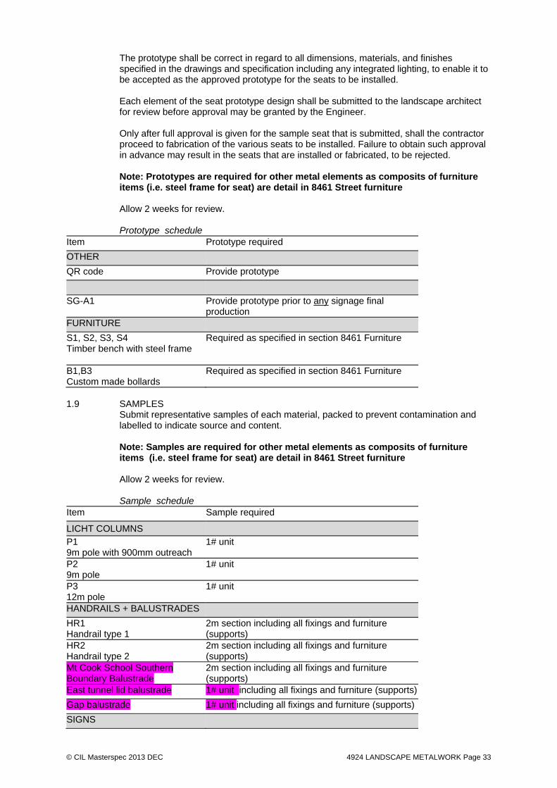
The prototype shall be correct in regard to all dimensions, materials, and finishes specified in the drawings and specification including any integrated lighting, to enable it to be accepted as the approved prototype for the seats to be installed. Each element of the seat prototype design shall be submitted to the landscape architect for review before approval may be granted by the Engineer. Only after full approval is given for the sample seat that is submitted, shall the contractor proceed to fabrication of the various seats to be installed. Failure to obtain such approval in advance may result in the seats that are installed or fabricated, to be rejected. Note: Prototypes are required for other metal elements as composits of furniture items (i.e. steel frame for seat) are detail in 8461 Street furniture Allow 2 weeks for review. Prototype schedule
Item Prototype required
OTHER
QR code Provide prototype
SG-A1 Provide prototype prior to any signage final production
FURNITURE
S1, S2, S3, S4 Timber bench with steel frame
Required as specified in section 8461 Furniture
B1,B3 Custom made bollards
Required as specified in section 8461 Furniture
1.9 SAMPLES
Submit representative samples of each material, packed to prevent contamination and labelled to indicate source and content. Note: Samples are required for other metal elements as composits of furniture items (i.e. steel frame for seat) are detail in 8461 Street furniture Allow 2 weeks for review. Sample schedule
Item Sample required
LICHT COLUMNS
P1 9m pole with 900mm outreach
1# unit
P2 9m pole
1# unit
P3 12m pole
1# unit
HANDRAILS + BALUSTRADES
HR1 Handrail type 1
2m section including all fixings and furniture (supports)
HR2 Handrail type 2
2m section including all fixings and furniture (supports)
Mt Cook School Southern Boundary Balustrade
2m section including all fixings and furniture (supports)
East tunnel lid balustrade 1# unit including all fixings and furniture (supports)
Gap balustrade 1# unit including all fixings and furniture (supports)
SIGNS

© CIL Masterspec 2013 DEC 4924 LANDSCAPE METALWORK Page 34
Item Sample required
SG-A1 Provide sample prior to any signage final production
SPECIAL FEATURES
QR code 1# unit
Pi2 Paving inlay (brass plate)
2m length – straight 2m length – on curve
FURNITURE
S1, S2, S3, S4 Timber bench with steel frame
Required as specified in section 8461 Furniture
B1,B3 Custom made bollards
Required as specified in section 8461 Furniture
1.10 VERIFY DETAILS AND DIMENSIONS Refer to drawings to ensure all required details and fixings are provided for in the
structural steelwork. Verify dimensions against site measurements prior to fabrication.
Tests + Engineers Certificates 1.11 TEST WELDING Non-destructive weld examination with method, extent and standards of acceptance to
AS/NZS 1554.1, Section 7 and NZS 3404.1, Appendix D. 1.12 CERTIFICATION OF LIGHT POLES Lightpole manufacture is required to meet and provide vertification in regards to building
consent PS1 requiremetns for all light poles including wind calculations.
Warranties 1.13 WARRANTY - MANUFACTURER/SUPPLIER Provide a material manufacturer/supplier warranty: 05 years: Metalwork 05 years: For powder coating finishes Provide this warranty on the manufacturer/supplier standard form. Commence the warranty from the date of practical completion of the contract works. Refer to the general section 1237 WARRANTIES for additional requirements. 1.14 WARRANTY - INSTALLER Provide an installer warranty: 05 years: Metalwork Provide this warranty on the installer/applicator standard form. Commence the warranty from the date of practical completion of the contract works. Refer to the general section 1237 WARRANTIES for additional requirements. 2. PRODUCTS Materials 2.1 BRONZE SHEET Phosphor bronze sheet/coil. 2.2 UNPAINTED HOT-DIP ZINC-COATED STEEL Hot-dip zinc-coated steel coil to AS 1397. Zinc coating class: ZM 275
© CIL Masterspec 2013 DEC 4924 LANDSCAPE METALWORK Page 35
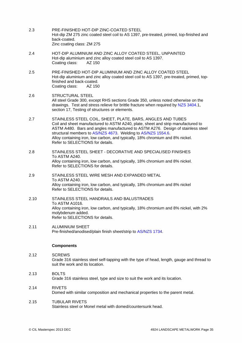
2.3 PRE-FINISHED HOT-DIP ZINC-COATED STEEL Hot-dip ZM 275 zinc coated steel coil to AS 1397, pre-treated, primed, top-finished and
back-coated. Zinc coating class: ZM 275 2.4 HOT-DIP ALUMINIUM AND ZINC ALLOY COATED STEEL, UNPAINTED Hot-dip aluminium and zinc alloy coated steel coil to AS 1397. Coating class: AZ 150 2.5 PRE-FINISHED HOT-DIP ALUMINIUM AND ZINC ALLOY COATED STEEL Hot-dip aluminium and zinc alloy coated steel coil to AS 1397, pre-treated, primed, top-
finished and back-coated. Coating class: AZ 150 2.6 STRUCTURAL STEEL All steel Grade 300, except RHS sections Grade 350, unless noted otherwise on the
drawings. Test and stress relieve for brittle fracture when required by NZS 3404.1, section 17, Testing of structures or elements.
2.7 STAINLESS STEEL COIL, SHEET, PLATE, BARS, ANGLES AND TUBES Coil and sheet manufactured to ASTM A240, plate, sheet and strip manufactured to
ASTM A480. Bars and angles manufactured to ASTM A276. Design of stainless steel structural members to AS/NZS 4673. Welding to AS/NZS 1554.6.
Alloy containing iron, low carbon, and typically, 18% chromium and 8% nickel. Refer to SELECTIONS for details. 2.8 STAINLESS STEEL SHEET - DECORATIVE AND SPECIALISED FINISHES To ASTM A240. Alloy containing iron, low carbon, and typically, 18% chromium and 8% nickel. Refer to SELECTIONS for details. 2.9 STAINLESS STEEL WIRE MESH AND EXPANDED METAL To ASTM A240. Alloy containing iron, low carbon, and typically, 18% chromium and 8% nickel Refer to SELECTIONS for details. 2.10 STAINLESS STEEL HANDRAILS AND BALUSTRADES To ASTM A1016. Alloy containing iron, low carbon, and typically, 18% chromium and 8% nickel, with 2%
molybdenum added. Refer to SELECTIONS for details. 2.11 ALUMINIUM SHEET Pre-finished/anodised/plain finish sheet/strip to AS/NZS 1734. Components 2.12 SCREWS Grade 316 stainless steel self-tapping with the type of head, length, gauge and thread to
suit the work and its location. 2.13 BOLTS Grade 316 stainless steel, type and size to suit the work and its location. 2.14 RIVETS Domed with similar composition and mechanical properties to the parent metal. 2.15 TUBULAR RIVETS Stainless steel or Monel metal with domed/countersunk head.
© CIL Masterspec 2013 DEC 4924 LANDSCAPE METALWORK Page 36
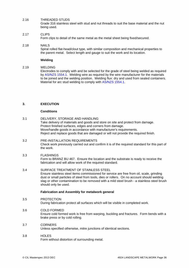
2.16 THREADED STUDS Grade 316 stainless steel with stud and nut threads to suit the base material and the nut
being used. 2.17 CLIPS Form clips to detail of the same metal as the metal sheet being fixed/secured. 2.18 NAILS Spiral rolled flat-head/clout type, with similar composition and mechanical properties to
the parent metal. Select length and gauge to suit the work and its location. Welding 2.19 WELDING Electrodes to comply with and be selected for the grade of steel being welded as required
by AS/NZS 1554.1. Welding wire as required by the wire manufacturer for the materials to be joined and the welding position. Welding flux: dry and used from sealed containers. Material for arc stud welding to comply with AS/NZS 1554.1.
3. EXECUTION Conditions 3.1 DELIVERY, STORAGE AND HANDLING Take delivery of materials and goods and store on site and protect from damage. Protect finished surfaces, edges and corners from damage. Move/handle goods in accordance with manufacturer's requirements. Reject and replace goods that are damaged or will not provide the required finish. 3.2 PRE-INSTALLATION REQUIREMENTS Check work previously carried out and confirm it is of the required standard for this part of
the work. 3.3 FLASHINGS Form to BRANZ BU 467. Ensure the location and the substrate is ready to receive the
fabrication and will allow work of the required standard. 3.4 SURFACE TREATMENT OF STAINLESS STEEL Ensure stainless steel items commissioned for service are free from oil, scale, grinding
dust or small particles of steel from tools, dies or rollers. On no account should welding slag or other contamination to be removed with a mild steel brush - a stainless steel brush should only be used.
Fabrication and Assembly for metalwork general 3.5 PROTECTION During fabrication protect all surfaces which will be visible in completed work. 3.6 COLD FORMED Ensure cold formed work is free from warping, buckling and fractures. Form bends with a
brake press or by cold rolling. 3.7 CORNERS Unless specified otherwise, mitre junctions of identical sections. 3.8 HOLES Form without distortion of surrounding metal.

© CIL Masterspec 2013 DEC 4924 LANDSCAPE METALWORK Page 37
3.9 MOVING PARTS When assembled, all moving parts must move freely and without binding. 3.10 CLEANING Remove all burrs and sharp arrises which would be visible after fixing, or a hazard to the
user. 3.11 AFTER CUTTING STAINLESS STEEL Grind off materials liable to corrode after thermal cutting. 3.12 BONDING Prepare surfaces of metals to receive adhesives by degreasing and abrading
mechanically or chemically. Use adhesives in accordance with the manufacturer's requirements. Form bond under pressure.
3.13 RIVETED JOINTS Draw riveted joints tightly together, with rivets closed to completely fill holes. 3.14 MECHANICAL JOINTS Ensure mechanical joints are tight with no visible gaps. 3.15 MECHANICAL JOINTS - ELEMENTS Bed in mastic all mechanical joints of elements which will be located externally, including
all mating surfaces, cleats and other fixings. 3.16 MECHANICAL JOINTS - CLEATS Unless specified otherwise connect cleats to frames with countersunk screws where they
will be visible after the component has been fixed and where raised heads would interfere with any moving part.
Application - generally 3.17 INSTALLATION Locate plugs accurately and use in accordance with the manufacturer's requirements.
Fix plumb, level and true to line. Comply with the specified standards, the reviewed shop drawings and installation details, including brackets, bolts, fixings, grout, bedding compounds and sealants.
3.18 LOADING Elements must not carry any structural load unless designed to do so. Do not use as
strutting or support when in place. Application - sheet steel 3.19 FABRICATE Fabricate and assemble in a workshop wherever practicable. 3.20 MARK OUT Mark out the work accurately, square and true to line allowing for correct radius folds and
laps to give the dimensions required for neat, close fits when in place. Use marking methods that do not damage, deface or cause future corrosive attack to the sheet metal being worked. Do not use carbon-based pencils with aluminium/zinc alloy coated metals.
3.21 CUT SHEETS Cut sheets by mechanical methods leaving edges true to line, square, smooth and free
from all burrs. Do not use abrasive cutting blades with aluminium/zinc alloy coated metals.
3.22 FORMING Use mechanical methods wherever possible and form and fold sheets square and true to
line and face free of all deformation and defects. Minimise cold-working and stress build-up and their effects by limiting the amount of working and avoiding sharp radius bends (minimum 1 x sheet thickness).

© CIL Masterspec 2013 DEC 4924 LANDSCAPE METALWORK Page 38
3.23 PRE-ASSEMBLE Pre-assemble in the workshop and match mark items for assembly or erection on site.
Do not strain, twist, bend or open such items to force them into the correct position while assembling or erecting.
3.24 SEPARATION Isolate dissimilar materials (metal and non-metal) in close proximity as necessary by
painting the surfaces or fitting separator strips. Place isolators between metals and treated timber and cement-based materials. Do not use unpainted lead sheet in contact with or allow water run-off onto zinc-coated and aluminium/zinc alloy coated metals. Refer also to BRANZ BU 467.
3.25 JOINING HOT-DIP ZINC-COATED STEEL Use self-secured seams, pop rivets, sealant strip, soldering and spot welding or a
combination as best suits the form and location of the work. 3.26 JOINING PRE-FINISHED HOT-DIP ZINC-COATED STEEL Neutral cure silicone and rivets as best suits the form and location of the work and the
supplier's stated requirements. 3.27 JOINING ALUMINIUM AND ZINC ALLOY COATED STEEL Use self-secured seams, pop rivets, sealant strip, or a combination as best suits the form
and location of the work. 3.28 JOINING PRE-FINISHED ALUMINIUM AND ZINC ALLOY COATED STEEL Neutral cure silicone and rivets as best suits the form and location of the work and the
supplier's stated requirements. 3.29 INSTALLATION Locate fixings accurately and use in accordance with the manufacturer's requirements.
Fix plumb, level and true to line. Comply with the installation details and complete with bedding compounds and sealants.
3.30 LOADING Ensure elements are fully supported unless designed to be self-supporting. Fabrication - welding 3.31 WELDING OF STAINLESS STEEL Weld stainless steel to BS EN 1011-3 and for structural steel to AS/NZS 1554.6. 3.32 PREPARATION FOR WELDING Remove grease, dirt, moisture and oxide from edges to be welded. Remove scale and
residue from arc and power cutting by machining or hand grinding. 3.33 ACCURACY Ensure accurate fit using clamps and jigs where practical. Use tack welds for temporary
attachment where jigging is not practical. 3.34 WELDS Make joints with parent and weld metal fully fused throughout with no inclusions, holes,
porosity or cracks. 3.35 WELDING STAINLESS STEEL Use double level butt welds, backing bars to remove heat, jigging, tack welds and any
other measures necessary to minimise distortion. Remove slight distortion by light hammering, taking care not to damage the surface finish.
3.36 SPATTER Prevent weld spatter falling on surfaces of materials which will be self finished and visible
in completed work.
© CIL Masterspec 2013 DEC 4924 LANDSCAPE METALWORK Page 39
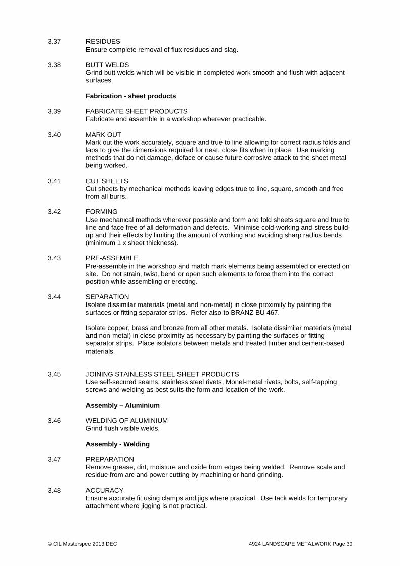
3.37 RESIDUES Ensure complete removal of flux residues and slag. 3.38 BUTT WELDS Grind butt welds which will be visible in completed work smooth and flush with adjacent
surfaces. Fabrication - sheet products 3.39 FABRICATE SHEET PRODUCTS Fabricate and assemble in a workshop wherever practicable. 3.40 MARK OUT Mark out the work accurately, square and true to line allowing for correct radius folds and
laps to give the dimensions required for neat, close fits when in place. Use marking methods that do not damage, deface or cause future corrosive attack to the sheet metal being worked.
3.41 CUT SHEETS Cut sheets by mechanical methods leaving edges true to line, square, smooth and free
from all burrs. 3.42 FORMING Use mechanical methods wherever possible and form and fold sheets square and true to
line and face free of all deformation and defects. Minimise cold-working and stress build-up and their effects by limiting the amount of working and avoiding sharp radius bends (minimum 1 x sheet thickness).
3.43 PRE-ASSEMBLE Pre-assemble in the workshop and match mark elements being assembled or erected on
site. Do not strain, twist, bend or open such elements to force them into the correct position while assembling or erecting.
3.44 SEPARATION Isolate dissimilar materials (metal and non-metal) in close proximity by painting the
surfaces or fitting separator strips. Refer also to BRANZ BU 467. Isolate copper, brass and bronze from all other metals. Isolate dissimilar materials (metal
and non-metal) in close proximity as necessary by painting the surfaces or fitting separator strips. Place isolators between metals and treated timber and cement-based materials.
3.45 JOINING STAINLESS STEEL SHEET PRODUCTS Use self-secured seams, stainless steel rivets, Monel-metal rivets, bolts, self-tapping
screws and welding as best suits the form and location of the work. Assembly – Aluminium 3.46 WELDING OF ALUMINIUM Grind flush visible welds. Assembly - Welding 3.47 PREPARATION Remove grease, dirt, moisture and oxide from edges being welded. Remove scale and
residue from arc and power cutting by machining or hand grinding. 3.48 ACCURACY Ensure accurate fit using clamps and jigs where practical. Use tack welds for temporary
attachment where jigging is not practical.
© CIL Masterspec 2013 DEC 4924 LANDSCAPE METALWORK Page 40
3.49 TACK WELDING Use only for temporary attachment unless otherwise specified. 3.50 WELDS Make joints with parent and weld metal fully fused throughout with no inclusions, holes,
porosity or cracks. 3.51 SPATTER Prevent weld spatter falling on surfaces of materials which will be self finished and/or
visible in completed work. 3.52 RESIDUES Ensure complete removal of flux residues and slag. 3.53 BUTT WELDS Finish butt welds which will be visible in completed work smooth and flush with adjacent
surfaces. 3.54 WELDING OF STEEL Use one of the following methods for welding steel: - gas welding - metal-arc welding to AS/NZS 1554.1 for mild steel - projection welding to BS 2630 - seam welding to BS 6265 Fabrication - handrails and balustrades 3.55 FABRICATE HANDRAILS AND BALUSTRADES Units to comply with the reviewed shop drawings and installation details, including
brackets, bolts, fixings, complete with all associated stainless steel componentry and hardware.
Installation - fabricated items 3.56 INSTALL FABRICATED ITEMS Install fabricated items in accordance with the manufacturer's requirements. Fix plumb,
level and true to line. Fix to comply with the reviewed shop drawings and installation details, including brackets, bolts, fixings, bedding compounds and sealants.
Installation - sheet products 3.57 INSTALL SHEET PRODUCTS Locate fixings accurately and use in accordance with the manufacturer's requirements.
Fix plumb, level and true to line. Fix to comply with the installation details and complete with brackets, bolts, fixings, bedding compounds and sealants.
3.58 SUPPORT Fully support elements unless designed to be self-supporting. Installation - handrails and balustrades 3.59 INSTALL HANDRAILS AND BALUSTRADES Install handrails and balustrades in accordance with the manufacturer's requirements.
Fix plumb, level and true to line. Fix to comply with the reviewed shop drawings and installation details, including brackets, bolts, fixings, bedding compounds and sealants, complete with all associated stainless steel componentry and hardware. Unless otherwise detailed installation to comply with NZBC F4/AS1.
Installation - signage

© CIL Masterspec 2013 DEC 4924 LANDSCAPE METALWORK Page 41
3.60 SIGN INSTALLATION Erect signposts vertical and plumb to the standard heights and offsets from the kerbs as
specified in MOTSAM.1. The base of signposts shall be concreted in below the paving level, and the paving brought up flush with the signpost.
Completion 3.61 ROUTINE CLEANING Carry out routine trade cleaning of this part of the work including periodic removal all
debris, unused and temporary materials and elements from the site. 3.62 DEFECTIVE OR DAMAGED WORK Repair damaged or marked elements. Replace damaged or marked elements where
repair is not possible or will not be acceptable. Adjust operation of equipment and moving parts not working correctly. Leave work to the standard required for following procedures.
3.63 PROTECTION Provide the following temporary protection of all finished work: 3.64 ENSURE Ensure all elements are free of marks or blemishes, with all moving parts working fully
and freely. 3.65 REPLACE Replace damaged, cracked or marked elements. 3.66 LEAVE Leave work to the standard required by following procedures. 3.67 REMOVE Remove all debris, unused materials and elements from the site. 4. SELECTIONS 4.1 LANDSCAPE EXTERNAL METALWORK
All metalwork as identified on the plans and details. Refer to detail for all member sizes LIGHT COLUMNS P1 Light pole: Supplier Sapa Description 9m pole with 900mm outreach (confirm on contract drawings) Material Aluminium Metal Grade Marine grade aluminium Finish Refer to 3711R RESENE PAINTING EXTERIOR Fixing Refer to drawing MP-11-90701 “ Light pole Details 1” P2 Light pole: Supplier Sapa Description 9m pole (confirm on contract drawings) Material Aluminium Metal Grade Marine grade aluminium Finish Refer to 3711R RESENE PAINTING EXTERIOR Fixing Refer to drawing MP-11-90701 “ Light pole Details 1” P3 Light pole: Supplier Sapa Description 12m pole (confirm on contract drawings) Material Aluminium Metal Grade Marine grade aluminium Finish Refer to 3711R RESENE PAINTING EXTERIOR Fixing Refer to drawing MP-11-90701 “ Light pole Details 1”
© CIL Masterspec 2013 DEC 4924 LANDSCAPE METALWORK Page 42
HANDRAILS + BALUSTRADES H1 Handrail type 1 Supplier Custom design Description Continuous post and rail handrail (roof fixed) With stanchion Material Stainless steel post + rail HDG steel stanchion post (allow for metal separation between SS rod
and HDG stanchion post) Metal Grade Stainless steel – 306
HDG posts - HDG600 Finish SS – No finish required HDG Stanchion - Refer to 3711R RESENE PAINTING EXTERIOR Fixing Root fixed Refer to drawing MP-11-90722 “ Furniture Details 3” H2 Handrail type 2 Supplier Custom design Description Rail + posts (wall mounted bracket) Material Stainless steel rail HDG steel wall bracket (allow for metal separation SS and HDG) Metal Grade Stainless steel – 306 HDG posts - HDG600 Finish Rail – No finish required Brackets - Refer to 3711R RESENE PAINTING EXTERIOR Fixing Wall mounted bracket Refer to drawing MP-11-90722 “ Furniture Details 3” Mt Cook school Southern boundary balustrade Supplier Custom design Description Fixing plate and pailings Material HDG steel fixing plate HDG steel pailings Metal Grade HDG600 Finish Refer to 3711R RESENE PAINTING EXTERIOR Fixing HDG plate fixed to concrete brick wall Refer to drawing MP-11-90740 “ Balustrade detail 1” East tunnel lid balustrade Supplier Custom design Description Frame and panel Material HDG steel flat frame HDG steel panels Integrated with tunnel name signage (HDG) Metal Grade HDG600 Finish Refer to 3711R RESENE PAINTING EXTERIOR Fixing HDG steel flat frame bolted to concrete upstand Refer to drawing MP-11-90535 “ East tunnel lid balustrade” Gap balustrade Supplier Custom design Description Base plate Railing Material HDG base plate Metal Grade HDG600 Finish Refer to 3711R RESENE PAINTING EXTERIOR Fixing HDG steel base plate fixed to precast underpass panels Refer to drawing MP-11-90540 “ Typical gap balustrade” FURNITURE B1 bollard
© CIL Masterspec 2013 DEC 4924 LANDSCAPE METALWORK Page 43
Supplier Custom design Description Timber bollard on metal frame. Material Aluminium Metal Grade Marine grade aluminium Finish Refer to 3711R RESENE PAINTING EXTERIOR Fixing Refer to drawing MP-11-90723 “ Bollards” S1, S2, S3 + S4 seat Supplier Custom design Description Timber seat on metal frame. Material Stainless steel Metal Grade 306 stainless steel Finish No finish required Fixing Refer to drawing MP-11-90720 “ Furniture details 1” MP-11-90721 “ Furniture details 2” SPECIAL FEATURES QR Code tile Supplier Custom design Description Laser cut QR code tile. Allow for code embedment and WebLink and
MCH review Material Cast bronze 150mmØ disc (confirm on contract drawings) Metal Grade Bronze Finish No finish required. Fixing Root fixed Refer to drawings Pi2 Paving inlay / historical reference Supplier Custom design Description Brass flat as drawn Material Cast brass Finish No finish required. Fixing Refer to drawing MP-11-90327 “Typical paving/kerb interface Details 8”
FENCES, GATES Sfn Steel fence (to Mount Cook School) Supplier Custom design Description Steel flats threaded by a steel round and fixed to boundary wall by flat Material HDG steel Metal Grade HDG600 Finish Refer to 3711R RESENE PAINTING EXTERIOR Fixing Wall fixed as per drawing MP-11-90740 “Balustrade details 1”
SIGNAGE SG-A1, SG-A2, SG-A3, SG-D1 Stainless steel letters Supplier Custom design Description lettering Material Stainless steel Metal Grade 306 stainless steel Finish Varies. Refer to contract drawings MP-11-09750 “Signage details” Fixing Varies. Refer to contract drawings MP-11-09750 “Signage details” SG-A3 (East tunnel lid signage) Stainless steel cut from balustrade Supplier Custom design
© CIL Masterspec 2013 DEC 4924 LANDSCAPE METALWORK Page 44
Description Stainless steel cut from balustrade Material Stainless steel Metal Grade 306 stainless steel Finish Varies. Refer to contract drawings MP-11-09750 “Signage details” Fixing Refer to drawing MP-11-90535 “ East tunnel lid balustrade” SG-C1, SG-C3, SG-C4 Stainless Steel signage signs Supplier Custom design Description Stainless steel signs (root fixed) Material Stainless steel Metal Grade 306 stainless steel Finish Varies. Refer to contract drawings MP-11-09750 “Signage details” Fixing Varies. Refer to contract drawings MP-11-09750 “Signage details” SG-E1 Glass fronted internally lit sign box Supplier Custom design Description Glass fronted internally lit sign box Material TBC Metal Grade TBC Finish Varies. Refer to contract drawings MP-11-09750 “Signage details” Fixing Varies. Refer to contract drawings MP-11-09750 “Signage details” SG-F1 Massay University sign Supplier Custom design Description TBC Material TBC Metal Grade TBC Finish Varies. Refer to contract drawings MP-11-09750 “Signage details” Fixing Varies. Refer to contract drawings MP-11-09750 “Signage details”
END OF SECTION

© CIL Masterspec 2013 SEP 6700R RESENE PAINTING GENERAL Page 45
6700R RESENE PAINTING GENERAL 1. GENERAL This section relates to the general matters related to Resene painting work. 1.1 RELATED WORK Refer to 6711R RESENE PAINTING EXTERIOR 1.2 ABBREVIATIONS AND DEFINITIONS Refer to the general section 1232 INTERPRETATION & DEFINITIONS for abbreviations
and definitions used throughout the specification. The following abbreviations apply specifically to this section: MPNZA Master Painters New Zealand Association Inc. Documents 1.3 DOCUMENTS Refer to the general section 1233 REFERENCED DOCUMENTS. The following
documents are specifically referred to in this section: Health and Safety in Employment Act 1992 MPNZA Specification manual 1.4 MANUFACTURER/SUPPLIER DOCUMENTS Manufacturer's and supplier's documents related to this section are: Resene One-Line specifications and product data manual (hard copy or at www.resene.co.nz) Resene Putting your safety first Copies of the above literature are available from Resene Telephone: 0800 RESENE (0800 737 363) Warranties 1.5 WARRANTY - MANUFACTURER/SUPPLIER Warrant this work under normal conditions of use against failure referring to the Resene
Promise of Quality in the Resene One-Line specifications and product data manual. Requirements This painting specification is written based on information available at the time of writing. 1.6 NO SUBSTITUTIONS Substitutions are not permitted to any specified Resene coating system, or associated
components and products. Do not combine paints from different manufacturers in a paint system.
If in the applicator's own expertise and judgement an amendment to this specification is
required, or where a substrate preparation, or required painting system is not covered in this specification, this shall be brought to the attention of the contract administrator and any amendment agreed before work proceeds any further.
1.7 QUALIFICATIONS Painters to be experienced competent workers, familiar with the materials and the
techniques specified and with the Resene coating systems and be members of the Master Painters New Zealand Association Inc.
The applicator is to have the necessary skill, experience and equipment to undertake the
work. The applicator remains responsible for ensuring proper completion of the work.

© CIL Masterspec 2013 SEP 6700R RESENE PAINTING GENERAL Page 46
Painters to be selected from the Resene Eco.Decorator programme. The Resene Eco.Decorator programme is designed to recognise a nationwide network of environmentally responsible, quality focussed painting contractors.
Refer to www.resene.co.nz/ecodecorator.htm for a list of Eco.Decorators in your area. 1.8 CONTROL SAMPLES Prepare samples of the finished work, including the specified preparation. Refer to
SELECTIONS for location and type. Obtain approval in writing of the appearance before proceeding. Use the Resene Architectural Sample Box as a basis of standard where appropriate.
Refer to 6711R RESENE PAINTING EXTERIOR 1.9 COLOUR SAMPLES Control reference: Check colours to Resene colour samples prior to application and keep
the Resene colour samples on site as a control reference. Colour matches are not permitted as they will differ in appearance, durability and performance to the original selected colour over the life of the coating. Samples of Resene colours may be ordered online from https://secure.clearfield.com/resene/SelectChart.asp?productType=3 or by calling 0800 RESENE (737 363). Use the Resene Architectural Sample Box as a basis of standard where appropriate.
1.10 PRIOR TO WORK COMMENCING Before any work commences painters should verify, with Architects or specifying
authority, that their paint matches a previously supplied standard card or panel. Differently coloured paints will vary in price, opacity and durability. Resene normally only specify two coats of colour but with certain colours, such as yellows and oranges, three coats may be needed. Refer to SELECTIONS for location and type.
1.11 SUPERVISED CONTROL SAMPLES Prepare samples of the finished work including the specified preparation. Refer to
SELECTIONS for location and type. Make arrangements for the supervision of the relevant stages. Obtain written approval before proceeding.
Supervised control samples may, after written approval, be used for comparative testing
of dry film thicknesses of the complete coating systems. 1.12 HEALTH AND SAFETY Refer to and comply with the requirements of the Health and Safety in Employment Act
1992 including the obligation to: - Eliminate hazards and if hazards cannot be eliminated or isolated, then minimise the
hazards in this work by using the proper equipment and techniques as required by the MPNZA Painters hazard handbook and Resene Putting your safety first handbook.
- Supply protective clothing and equipment. - Inform the contractor as well as the employees and others on site of those hazards and
put in place procedures for dealing with emergencies. 1.13 SAFETY DATA SHEETS Obtain from Resene (phone 0800 RESENE, or www.resene.co.nz) the safety data sheet
for each product used and comply with the required safety procedures. Keep sheets on site.
Performance 1.14 RESENE INSPECTION Permit representatives of Resene to inspect the work in progress and to take samples of
their products from site if requested. Resene will take care when inspecting the work, but does not accept any responsibility for the proper completion of the work before or after such inspection.
© CIL Masterspec 2013 SEP 6700R RESENE PAINTING GENERAL Page 47
1.15 INSPECTION OF THE WORK Inspection of the whole of the work at each of the stages set out in SELECTIONS may be
made. Agree on a programme that will facilitate such inspection, including notification when each part and stage of the work is ready for inspection.
2. PRODUCTS Materials 2.1 MATERIALS GENERALLY Do not combine paints from different manufacturer's in a paint system. Use only Resene products (which are guaranteed for consistency and performance under
AS/NZS ISO 9001 and APAS) prepared, mixed and applied as directed in the Resene One-Line Specifications and Product Data Manual. This specification has been written using where practical and available both low/no VOC and Environmental Choice approved products.
2.2 EXPOSED DARK COLOURS Darker colours in areas of high sun exposure place significant stress on the coating and
substrate. Resene 'CoolColour' technology reduces heat absorption of a wide range of colours. Contact your local Resene Representative or visit www.resene.co.nz for more information or visit www.resene.co.nz/coolcolour. View a list of Resene colours that can be made using Resene CoolColour technology at www.resene.co.nz/colourlibrary.
2.3 THINNERS/ADDITIVES Use only if and when expressly directed by Resene for their particular product in a
particular application. Always wear gloves when handling any solvents including turpentine as harmful chemicals may be absorbed into the body through the skin.
Accessories 2.4 ACCESSORIES Contact your local Resene ColorShop for a full range of accessories and usage advice. 3. EXECUTION Conditions 3.1 EXECUTION To conform to required trade practice, which shall be deemed to include those methods,
practices and techniques contained in the Master Painters New Zealand Association Inc. Specification manual.
3.2 TREATED SURFACES Where surfaces have been treated with preservatives or fire retardants, check with the
treatment manufacturer that coating materials are compatible with the treatment and do not inhibit its performance. If they are not compatible, obtain instructions before proceeding.
3.3 ANCILLARY SURFACES The descriptions of areas in schedules and elsewhere are of necessity simplified. Coat
ancillary exposed surfaces to match similar or adjacent materials or areas, except where a fair-faced natural finish is required or items are completely prefinished. In cases of doubt obtain written instructions before proceeding.
3.4 HARDWARE Do not paint hinges or hardware that cannot be removed. Before commencing work
carefully remove hardware, fixtures and fittings, set aside where they cannot be damaged or misplaced and replace on completion. Refer to SELECTIONS for hardware, fixtures and fittings for removal.

© CIL Masterspec 2013 SEP 6700R RESENE PAINTING GENERAL Page 48
3.5 PROTECTION Supply, lay and fix dropsheets, coverings and masking necessary to protect adjoining,
fixtures, fittings and spaces from paint drops, spots, spray and damage. Application - preparatory work 3.6 SURFACE PREPARATION Refer to the Resene One-Line specifications and product data manual for surface
preparation sheets (or obtain them by phoning 0800 RESENE, or at www.resene.co.nz) listed in the materials systems schedule clauses. Carry out the preparatory work required by them for each of the substrates.
3.7 SHARP EDGES, CRACKS AND HOLES Remove and/or repair sharp edges, cracks and holes if present, as outlined in the
preamble of the Resene One-Line specifications and product data manual. Elastomeric sealants, if used, should not be painted. The paint film will not match the
flexibility of the sealant and may severely limit its effectiveness. 3.8 REMEDIAL WORK If any substrate or surface, that even with the preparation work called for in this section,
cannot be brought up to a standard that will allow painting or clear finishing of the required standard then do not proceed until remedial work is carried out.
3.9 GAP FILLING Make good cracks, holes, indented and damaged surfaces. Use suitable gap fillers to
match the surface being prepared. Any special priming requirements of the fillers must be satisfied. Allow to dry or set before sanding back level with the surface. Prime or seal timber before using putty.
Exterior and wet areas: Use only Portland cement base or water-insoluble organic base
gap fillers. 3.10 OFF-SITE WORK Carry out this work under cover in a suitable environment with suitable lighting. Store
items, both before and after coating, in a clean, dry area protected from the weather and mechanical damage, properly stacked and spaced to allow air circulation and to prevent sticking.
3.11 PRIMING JOINERY Pre-treat any cut surfaces of preservative treated timber before priming. Ensure L.O.S.P.
treated joinery has dried sufficiently to lose solvent odour. Pre-treat bare timber with Resene TimberLock (see Data Sheet D48) to improve the durability of subsequent coats.
Liberally coat end grain, allow to soak in and then recoat. 3.12 CONCEALED JOINERY SURFACES Where off-site coatings are specified they must be applied to surfaces including those
concealed when incorporated into the building. 3.13 CONCEALED METAL SURFACES Apply primer to suit the coating system to surfaces which will be concealed when
incorporated into the building. 3.14 EXTERNAL DOORS Prime or seal and paint bottom edges before hanging. 3.15 BEAD GLAZING Stained, varnished, or painted joinery to have the first two coats, or the primer and one
undercoat, applied to rebates and beads before glazing.

© CIL Masterspec 2013 SEP 6700R RESENE PAINTING GENERAL Page 49
3.16 PUTTY FRONTING According to the putty manufacturer's instructions allow putty to set, then prime with
Resene Wood Primer (see Data Sheet D40). Fully protect the putty by completing the Resene coating system as soon as it is sufficiently firm.
Application - generally 3.17 PAINTING GENERALLY Comply with the Resene One-Line specifications and product data manual data sheets
and the additional requirements of this work section. Ensure large wall areas that require more than one container of paint per coat, have
enough paint boxed (mixed) together to complete the final coat. This will not apply if a single factory batch of paint, rather than shop tinted paint, is applied.
3.18 MIXING Although generally supplied ready-mixed, thoroughly mix paints. Lift any settled pigment
and ensure the paint is homogenous. 3.19 ENVIRONMENT Defer painting of exterior surfaces until weather conditions are favourable - warm dry
days without frost or heavy dews. Avoid painting in direct sunlight any surfaces that absorb heat excessively. As far as possible apply paint in the temperature range 15°C to 25°C. If temperatures fall outside the range of 10°C and 35°C do not paint unless paints with the necessary temperature tolerance have been specified. Do not apply solvent borne paint if moisture is present on the surface.
3.20 SEQUENCE OF OPERATIONS Painting work to generally follow the following sequences: - Complete surface preparation before commencing painting. - Apply primers, sealers, stains, undercoats, paints and clear coatings in the sequences
laid down by Resene. - Allow the full drying time between coats laid down by Resene. - Do not expose primers, undercoats and intermediate coats beyond Resene's
recommendations before applying the next coat. - Finish broad areas before painting trim. - Ensure batch numbers of tins are matched for whole areas. - Internally, paint ceilings before walls and walls before joinery, trim and other items. 3.21 APPLICATION Select brush, roller, or pad and apply coatings to the requirements of Resene to obtain a
smooth, even coating of the specified thickness, uniform gloss and colour. 3.22 LIGHTLY SAND Lightly sand primers, sealers, undercoats and intermediate coats to remove dust pick-up,
protruding fibres and coarse particles. Complete by removing dust immediately before applying the next coat.
3.23 DEFECTIVE WORK Correct defective work immediately and recoat as required, following precisely the
Resene system being applied. 3.24 EACH COAT Each coat of paint and the completed paint system to have the following qualities and
properties: - Uniform finish, colour, texture, sheen and hiding power and the proper number of coats
applied. - No blemishes such as runs, sags, crinkling, fat edges, entrained paint skins, hairs, dust,
bare or starved patches, cracks, brush marks, ladder marks and blistering. - Proper covering of corners, crannies, thin edges, cracks, end grain and other difficult
places of application. Completion

© CIL Masterspec 2013 SEP 6700R RESENE PAINTING GENERAL Page 50
3.25 CLEAN Clean adjoining surfaces, glass and fittings of any paint contamination. Clean off glass
indicators at the completion of the building works. Clean glass inside and out to a shining finish. Use the Resene Washwise on site 'paint equipment clean-up water' reclamation system to minimise the environmental impact of cleaning paint application tools.
3.26 LEAVE Leave the whole of this work uniform in gloss and colour, of correct thickness, free from
painting defects, clean and unmarked and to the standard required by following procedures.
3.27 REMOVE Remove dropsheets, coverings and masking to leave surrounding surfaces and areas
clean, tidy and undamaged. Remove debris, unused materials and elements from the site.
3.28 REPLACE Replace hardware without damage to it or the adjoining surface and leave hardware
properly fitted and in working order. 3.29 DISPOSAL OF PAINTS AND THINNERS Note: The use and disposal of paint and thinners represents a significant environmental
hazard. Ensure all paint and thinners are disposed of in the following manner: - When requested hand over part used paint containers to client for maintenance touch
ups. - Recycle leftover paint at a Resene ColorShop as part of the Resene "Paintwise
programme". Contact your local Resene ColorShop for details or view information online at www.resene.co.nz/paintwise.htm.
- Donate left over paint to local community groups. - Solvent based paints, paint thinners, turpentine, mineral spirits and solvents require
special disposal procedures. Do not pour down sewer or storm water drains, sinks or into the ground. If they cannot be recycled they must be disposed of in a refuse dump licensed to take toxic waste.
3.30 MAINTENANCE Good maintenance of coating systems involves a routine of regular cleaning as well as
regular inspections. Regular inspections of the coating systems are recommended to identify breakdown, accidental damage to or undesirable deterioration of the paint.
Refer the Resene Caring for your paint finish brochure and the Resene website, www.resene.co.nz/comn/services/maintenance.htm.
4. SELECTIONS 4.1 SELECTIONS Refer to 6711R RESENE PAINTING EXTERIOR for selections.

© CIL Masterspec 2013 SEP 6700R RESENE PAINTING GENERAL Page 51
Emspkw
CCooaattiinnggss SSppeecciiffiiccaattiioonn
Contract: EXTERIOR PAINTING
Building: MEMORIAL PARK
Location: MOUNT COOK, WELLINGTON.
Owner / Agent WALA
Specification: M109-12-13 Date: 19/12/13
Writer: Craig Ell SCOPE The work involved and intended in this Contract to be carried out at the location detailed
above comprises the following: Prepare surfaces and apply Resene paint in accordance with this specification. GUARANTEE The Contractor guarantees this work under normal conditions of use against failure of: Materials: According to 1(v) Durability of Paint Systems in the Resene Paints One-Line Specifications and Product Data Manual. The Contractor is to guarantee their work against all defects that may occur within three
months from the completion of the contract and will be required to make good such defects at their own cost. Such defects specifically exclude damage, or consequential damage, caused by third parties which are the responsibility of the main contractor.
INSURANCE
The Contractor shall provide adequate Public Liability insurance. © Copyright- Resene Paints Limited, 2003.
All rights reserved. All information and material contained herein, including any colour scheme specifications and Resene RenderRite renders are subject to copyright and remain the exclusive property of Resene. This information and material is prepared for the exclusive use of Resene clients, for use with Resene products and services, on projects specified by Resene. All information and material must only be used for the purpose for which they have been expressly supplied. Resene reserves the right to take legal action for breach of these conditions and its rights.

© CIL Masterspec 2013 SEP 6700R RESENE PAINTING GENERAL Page 52
1.0 NEW EXTERIOR MILL ALUMINIUM LIGHT POLES AND BOLLARDS ETC – IMPERITE
IF-503 METALLIC Condition: New Aluminium to be fabricated and painted off site in Resene ArmourCote 220 two
pack inhibitive epoxy and Imperite IF503 metallic two pack acrylic epoxy, with a clear coat of Uracryl 404, allowing for possible on site touch ups due to damage.
Note 1: Before fixing new Aluminium in place, any faces of the structure that cannot be painted
later should be thoroughly degreased then primed with Resene Armourcote 220 Primer. Note 2: Wind blown salt deposits should be thoroughly washed off with copious amounts of
water and the surfaces allowed to dry before painting commences and at the beginning of each day’s painting.
Note 3: This specification assumes that the metalwork has not been welded nor damaged in transit
to the site. If this is not the case a new specification will be required. PREPARATION FOR PAINTING: 1.1 Mix one part of Resene Roof & Metal Wash with three parts of fresh water. Apply a liberal
wash of this mixture to the surface with a nylon bristle brush or broom. Thoroughly scrub the surface to ensure complete removal of all grease and other contaminants. Rinse thoroughly with fresh water and allow to dry. Data Sheet D88
Note 4: The contractor shall ensure that there is no deterioration in the condition of the surfaces to be painted between the actual preparation and the application of the priming paint. Any extraneous matter deposited before painting shall be completely removed and the surface restored to its prepared finish state
PAINTING: 1.4 Apply Resene Armourcote 220 Primer to achieve a dry film thickness of 75 microns.Data
Sheet RA34 Note 5: For areas that will not be naturally washed by rain and where dirt & salts may accumulate
(for example the underside of canopies) we recommend two full coats of primer. 1.5 Apply Resene Imperite I.F. 503 Metallic by spray to achieve a dry film build of 75 microns.
Allow 48 hours to fully cure before overcoating with Uracryl. Data Sheet RA81a 1.6 Apply Resene Uracryl 404 Clear to achieve a dry film build of 50 microns. Data
Sheet RA59 Note 6: Resene Paints Limited recommend that, prior to applying aluminium flake type finishing
coats, that a standard panel is first prepared using the intended application equipment (airless spray is strongly recommended) and that this panel is approved for colour and pattern by the owners/architects. This panel should include the clear coating. Where a roller is used by a skilled applicator to apply the product the final finish on a smooth surface will be at best comparable to 80% of the effect achieved by spray. This is due to the impacts of rolling on flake alignment.
ATTENTION - ISOCYANATES

© CIL Masterspec 2013 SEP 6700R RESENE PAINTING GENERAL Page 53
The OSH ‘Approved Code of Practice for the Safe Use of Isocyanates’ should be read and followed if Uracryl is to be spray applied.
2.0 NEW EXTERIOR HDG STEEL BINS, BALUSTRADES, PLATES, BRACKETS ETC -
IMPERITE IF-503 METALLIC Condition: New steel to be fabricated Galvanised and painted off site in Resene ArmourCote 220
two pack inhibitive epoxy and Imperite IF503 metallic two pack acrylic epoxy, with a clear coat of Uracryl 404 allowing for possible on site touch ups due to damage.
Note 1: Before fixing new galvanised steel in place, any faces of the structure that cannot be
painted later should be thoroughly degreased then primed with Resene Armourcote 220 Primer.
Note 2: This specification assumes the Hot Dip Galvanised coating has been applied as per the
current accepted AS/NZS Standard, is even in appearance and is in sound condition. “Bare spots” will not be accepted and if present, please contact the writer for rectification processes. The coating should be at least 75 microns thick in all areas provided that the steel is of the appropriate thickness.
Note 3: Wind blown salt deposits should be thoroughly washed off with copious amounts of
water and the surfaces allowed to dry before painting commences and at the beginning of each day’s painting.
Note 4: This specification assumes that the steelwork has not been welded nor damaged in transit
to the site. If this is not the case a new specification will be required. PREPARATION FOR PAINTING: 2.1 Mix one part of Resene Roof & Metal Wash with three parts of fresh water. Apply a liberal
wash of this mixture to the surface with a nylon bristle brush or broom. Thoroughly scrub the surface to ensure complete removal of all grease and other contaminants. Rinse thoroughly with fresh water and allow to dry. Data Sheet D88
2.2 In marine areas (or if Galv. has been left unpainted for a long period) we strongly recommend water-blasting to remove any sea salts that may have accumulated over time. Wind blown salt deposits should be thoroughly washed off with copious amounts of water and the surfaces allowed to dry before painting commences and at the beginning of each day’s painting.
2.3 Carefully whip-blast (sweep blast) the surface to remove any chromate residue and to
provide a slightly roughened surface profile using clean new non-metallic blasting media. Care must be taken to ensure a minimum amount of zinc is removed during this process (no more than 10um). Any areas of white corrosion must be totally removed during this process before painting.
Note 4: The contractor shall ensure that there is no deterioration in the condition of the surfaces to be painted between the actual preparation and the application of the priming paint. Any extraneous matter deposited before painting shall be completely removed and the surface restored to its prepared finish state
PAINTING:

© CIL Masterspec 2013 SEP 6700R RESENE PAINTING GENERAL Page 54
2.4 Apply Resene Armourcote 220 Primer to achieve a dry film thickness of 75 microns.Data Sheet RA34
Note 5: For areas that will not be naturally washed by rain and where dirt & salts may accumulate (for example the underside of canopies) we recommend two full coats of primer.
2.5 Apply Resene Imperite I.F. 503 Metallic by spray to achieve a dry film build of 75 microns.
Allow 48 hours to fully cure before overcoating with Uracryl. Data Sheet RA81a 2.6 Apply Resene Uracryl 404 LS Clear to achieve a dry film build of 50 microns. Data Sheet RA59 OFF SITE PAINTING TO DAMAGED OR WELDED AREAS 2.7a To repaired areas of welds or damaged steel only apply Resene Armourzinc 120 to
achieve a dry film thickness of 75 microns. Ensure an overlap onto sound existing coatings of 10mm. Take care to achieve a uniform finish. Data Sheet RA22
2.8a Apply Resene Armourcote 221 to achieve a dry film thickness of 75 microns. Ensure an
overlap onto sound existing coatings of 10mm. Take care to achieve a uniform finish.Data Sheet RA36
2.9a Apply Resene Imperite IF503 to achieve a dry film build of 50 microns. Ensure an overlap
onto sound existing coatings of 10mm. Take care to achieve a uniform finish.Data Sheet RA55
2.10a Apply Resene Uracryl 404 LS Clear to achieve a dry film build of 50 microns. Data Sheet RA59 Note 6: On completion of painting, all crevices shall have a suitable type silicon or mastic sealant
applied into the as per manufacturer’s instruction to aid in corrosion prevention. Note 7: Resene Paints Limited recommend that, prior to applying aluminium flake type finishing
coats, that a standard panel is first prepared using the intended application equipment (airless spray is strongly recommended) and that this panel is approved for colour and pattern by the owners/architects. This panel should include the clear coating. Where a roller is used by a skilled applicator to apply the product the final finish on a smooth surface will be at best comparable to 80% of the effect achieved by spray. This is due to the impacts of rolling on flake alignment.
ATTENTION - ISOCYANATES The OSH ‘Approved Code of Practice for the Safe Use of Isocyanates’ should be read and followed if Uracryl is to be spray applied.
3.0 NEW EXTERIOR HARDWOOD TIMBER BOLLARDS, BENCH SEATS, INCL BRIDGE
AND STEPS – OILED FINISH Condition: New timber to be oiled in Resene Furniture and Decking Oil with the
first coat to be applied if possible prior to construction. Note1 : Resene Furniture and Decking Oil is not intended for high traffic areas

© CIL Masterspec 2013 SEP 6700R RESENE PAINTING GENERAL Page 55
Note2 : A trial area or panel is required prior to work being undertaken to ensure to desired finish can be achieved. All parties involved should agree that trial area is acceptable before proceeding.
Note3 : For best results Resene Paints Limited recommend that the backs of boards be sealed with
a full coat of Resene Furniture and Decking Oil. End grains should ideally be sealed with two coats of Resene Furniture and Decking Oil. The performance of the stain will be improved if any sharp edges on the timber profile
PREPARATION FOR STAINING: 3.1 Ensure all surfaces are clean and free from contamination. Sand any sharp edges to a
rounded profile. Any bare timber that has been left to weather longer than one month, should be thoroughly sanded back to a sound timber surface, inspected for mould & if necessary, treated with Resene Moss & Mould Killer and left for 48 hours. Data Sheet D80
3.2 Thoroughly scrub down using a 16% solution of Resene Timber and Deck Wash and fresh
water. Rinse clean with fresh water. Data Sheet D813 Note: Avoid skin contact. Timber must be allowed to dry out thoroughly before painting. STAINING: 3.3 Apply Resene Furniture and Decking Oil by brush, roller or spray saturating the surface at
10-12 square metres per litre (this may vary depending on porosity of the timber). 3.4 Wipe off excess Resene Furniture and Decking Oil with a dry, lint free, absorbent cloth along
the grain.

© CIL Masterspec 2013 SEP 6700R RESENE PAINTING GENERAL Page 56
OPTION A 4.0 NEW EXTERIOR HARDWOOD TIMBER BRIDGE AND STEPS ONLY – WOOD OIL STAIN Condition: New timber to be stained in Resene Wood Oil Stain, with the first coat to be applied prior
to all surfaces before construction commences. Note 1: For best results Resene Paints Limited recommend that the backs of boards be sealed with
a full coat of Resene Solventborne Woodsman. End grains should ideally be sealed with two coats of Resene Solventborne Woodsman. The performance of the stain will be improved if any sharp edges on the timber profile are rounded off. Solventborne Woodsman is designed to slowly erode away in exposed places and may need regular maintenance.
Note 2: If timber is LOSP Preservative treated then it must not be painted if solvents from the
LOSP treatment are still in the timber. Many problems may be encountered with the new paint system if timber is painted while these solvents are still in the timber.
PREPARATION FOR STAINING: 4.1 Ensure all surfaces are clean and free from contamination. Sand any sharp edges to a
rounded profile. Any bare timber that has been left to weather longer than one month, should be thoroughly sanded back to a sound timber surface, inspected for mould & if necessary, treated with Resene Moss & Mould Killer and left for 48 hours. Data Sheet D80
4.2 Thoroughly scrub down using a 16% solution of Resene Timber and Deck Wash and fresh
water. Rinse clean with fresh water. Data Sheet D813 Note: Avoid skin contact. Timber must be allowed to dry out thoroughly before painting. STAINING: 4.3 Apply a full coat of Resene Solventborne Woodsman at 3-14 square metres per litre
depending on porosity of the surface. Data Sheet D57 4.4 Apply a finishing coat of Resene Solventborne Woodsman taking care to avoid an excessive
build of stain on top of the timber. The application rate for the second coat will generally be much less than that for the first. Any material that is still tacky after overnight drying should be wiped off with a Turps wet cloth.
Note 3: Spreading rates for Solventborne Woodsman depend on the roughness of the timber.
Check the data sheet for details. Note 4: Regular 18 monthly maintenance of exposed areas is recommended. Note 5: “The specified coating system for this substrate may, in wet conditions, become very slippery and
dangerous.”

© CIL Masterspec 2013 SEP 6700R RESENE PAINTING GENERAL Page 57
Surface texture and abnormal surface porosity will effect either the spreading rate or the
coverage achieved. Allowance for this should be made in the quotation. This specification should be read in conjunction with the manufacturers recommendations
contained in the relevant technical data sheets. Site Assistance Resene Representatives will visit specific job sites as required to assist with advice on
adequacy of preparation; special mixing requirements; standard of application etc. However this should not be regarded as ‘supervision’, but simply ‘site assistance’.
Craig Ell Rob Mountford Thorndon Quay Head Office, Lower Hutt Architectural Services Representative Technical Services Manager
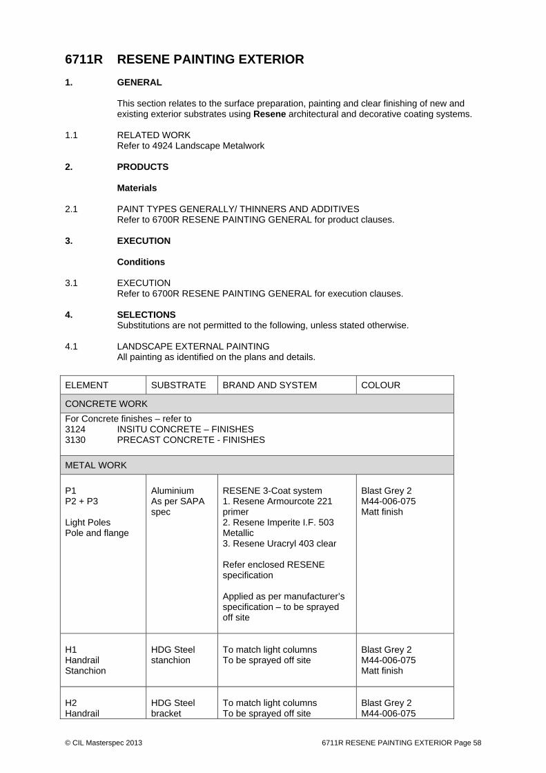
© CIL Masterspec 2013 6711R RESENE PAINTING EXTERIOR Page 58
6711R RESENE PAINTING EXTERIOR 1. GENERAL This section relates to the surface preparation, painting and clear finishing of new and
existing exterior substrates using Resene architectural and decorative coating systems. 1.1 RELATED WORK Refer to 4924 Landscape Metalwork 2. PRODUCTS Materials 2.1 PAINT TYPES GENERALLY/ THINNERS AND ADDITIVES Refer to 6700R RESENE PAINTING GENERAL for product clauses. 3. EXECUTION Conditions 3.1 EXECUTION Refer to 6700R RESENE PAINTING GENERAL for execution clauses. 4. SELECTIONS Substitutions are not permitted to the following, unless stated otherwise. 4.1 LANDSCAPE EXTERNAL PAINTING All painting as identified on the plans and details.
ELEMENT SUBSTRATE BRAND AND SYSTEM COLOUR
CONCRETE WORK
For Concrete finishes – refer to 3124 INSITU CONCRETE – FINISHES 3130 PRECAST CONCRETE - FINISHES
METAL WORK
P1 P2 + P3 Light Poles Pole and flange
Aluminium As per SAPA spec
RESENE 3-Coat system 1. Resene Armourcote 221 primer 2. Resene Imperite I.F. 503 Metallic 3. Resene Uracryl 403 clear Refer enclosed RESENE specification Applied as per manufacturer’s specification – to be sprayed off site
Blast Grey 2 M44-006-075 Matt finish
H1 Handrail Stanchion
HDG Steel stanchion
To match light columns To be sprayed off site
Blast Grey 2 M44-006-075 Matt finish
H2 Handrail
HDG Steel bracket
To match light columns To be sprayed off site
Blast Grey 2 M44-006-075
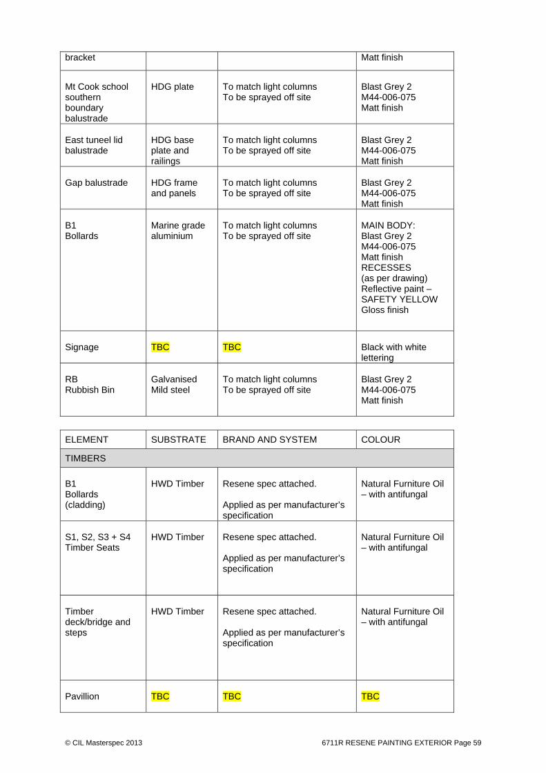
© CIL Masterspec 2013 6711R RESENE PAINTING EXTERIOR Page 59
bracket Matt finish
Mt Cook school southern boundary balustrade
HDG plate
To match light columns To be sprayed off site
Blast Grey 2 M44-006-075 Matt finish
East tuneel lid balustrade
HDG base plate and railings
To match light columns To be sprayed off site
Blast Grey 2 M44-006-075 Matt finish
Gap balustrade
HDG frame and panels
To match light columns To be sprayed off site
Blast Grey 2 M44-006-075 Matt finish
B1 Bollards
Marine grade aluminium
To match light columns To be sprayed off site
MAIN BODY: Blast Grey 2 M44-006-075 Matt finish RECESSES (as per drawing) Reflective paint – SAFETY YELLOW Gloss finish
Signage
TBC
TBC
Black with white lettering
RB Rubbish Bin
Galvanised Mild steel
To match light columns To be sprayed off site
Blast Grey 2 M44-006-075 Matt finish
ELEMENT SUBSTRATE BRAND AND SYSTEM COLOUR
TIMBERS
B1 Bollards (cladding)
HWD Timber
Resene spec attached. Applied as per manufacturer’s specification
Natural Furniture Oil – with antifungal
S1, S2, S3 + S4 Timber Seats
HWD Timber
Resene spec attached. Applied as per manufacturer’s specification
Natural Furniture Oil – with antifungal
Timber deck/bridge and steps
HWD Timber
Resene spec attached. Applied as per manufacturer’s specification
Natural Furniture Oil – with antifungal
Pavillion
TBC
TBC
TBC

© CIL Masterspec 2013 6711R RESENE PAINTING EXTERIOR Page 60
Crèche timber fence/ screen and gate
Glulam Econo
Top Coat : Resene Enamacryl Gloss Waterborne enamel. Priming, undercoat and top coat applications as per manufacturer’s specification
White
Timber deck slip resistance
HWD timber
Allow for 50mm wide X1200mm long strips painted to each decking timber. Resene Anti Slip coating. Epoxy paint finish with slip resistance TO NZS To Landscape Architects approval
Black

© CIL Masterspec 2013 6711R RESENE PAINTING EXTERIOR Page 61
ELEMENT SUBSTRATE BRAND AND SYSTEM COLOUR
OTHER SURFACES
Road marking Paint
To Engineers specification
Concrete
Sealer and anti-graffiti coating as specified in 3124 FINISHES TO WET CONCRETE
4.1 CONTROL SAMPLES / 4.2 SUPERVISED CONTROL SAMPLES Refer to section 1 above
END OF SECTION
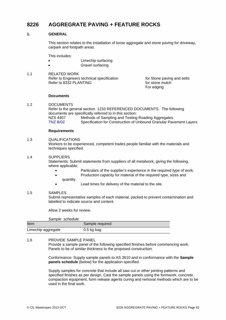
© CIL Masterspec 2013 OCT 8226 AGGREGRATE PAVING + FEATURE ROCKS Page 62
8226 AGGREGRATE PAVING + FEATURE ROCKS 1. GENERAL This section relates to the installation of loose aggregate and stone paving for driveway,
carpark and footpath areas. This includes:
Limechip surfacing Gravel surfacing
1.1 RELATED WORK
Refer to Engineers technical specification for Stone paving and setts Refer to 8332 PLANTING for stone mulch For edging
Documents 1.2 DOCUMENTS Refer to the general section 1233 REFERENCED DOCUMENTS. The following
documents are specifically referred to in this section: NZS 4407 Methods of Sampling and Testing Roading Aggregates TNZ B/02 Specification for Construction of Unbound Granular Pavement Layers Requirements 1.3 QUALIFICATIONS Workers to be experienced, competent trades people familiar with the materials and
techniques specified. 1.4 SUPPLIERS
Statements: Submit statements from suppliers of all metalwork, giving the following, where applicable;
Particulars of the supplier’s experience in the required type of work. Production capacity for material of the required type, sizes and
quantity. Lead times for delivery of the material to the site.
1.5 SAMPLES
Submit representative samples of each material, packed to prevent contamination and labelled to indicate source and content. Allow 2 weeks for review. Sample schedule
Item Sample required
Limechip aggregate 0.5 kg bag
1.6 PROVIDE SAMPLE PANEL Provide a sample panel of the following specified finishes before commencing work.
Panels to be of similar thickness to the proposed construction.
Conformance: Supply sample panels to AS 3610 and in conformance with the Sample panels schedule (below) for the application specified. Supply samples for concrete that include all saw cut or other jointing patterns and specified finishes as per design. Cast the sample panels using the formwork, concrete, compaction equipment, form release agents curing and removal methods which are to be used in the final work.
© CIL Masterspec 2013 OCT 8226 AGGREGRATE PAVING + FEATURE ROCKS Page 63
Samples shall be made and kept in an area remote from the designated locations for the constructed concrete elements that are to be installed. Do not proceed with the related work until the acceptable range of surface treatments has been determined.
1.7 SAMPLE PANEL SCHEDULE (For precast samples refer to section 3130) code Panel / sample Incorporated features Panel Sizes SURFACING
LLCP Limechip paving Colour and aggregate sample
2 mx 2m
1.8 INSPECTIONS
Give notice so inspection may be made of the following: Setting out completed. Feature rock delivery Feature rock placement
2. PRODUCTS Materials 2.1 LIMECHIP PAVING - AGGREGATE High quality calcium carbonate (CaCO3) aggregate. Aggregate size: 5mm to fines Composition Crushed lime shall be 2 parts Lime Flour to 1 part Aggregate The chip and flour shall be thoroughly mixed at the quarry before transportation. Limechip material shall be clear and free of any extraneous matter. 2.2 FEATURE ROCKS Feature rocks. Refer to SELECTIONS. 3. EXECUTION Conditions 3.1 SETTING OUT Set out to the dimensions shown on the drawings. Construct footpaths in to levels, grades and cross falls matching the surrounding ground
levels. Ensure that the finished level of the path matches the surrounding ground level without ponding on the path or on adjoining ground.
3.2 FORMATION TO SUBGRADE LEVEL Complete the formation to subgrade level to leave it well compacted, firm, and free from
any weak spots or loose material. Remove all topsoil from the construction width of the footpath, and remove to stockpile
onsite. Where the excavation to subgrade has not removed all the topsoil or contains weak
material, undercut works material to a firm base and supply and install GAP 40 aggregate to make up levels to the subgrade level.
3.3 FORMATION ON SIDLING SLOPE Cut so that the subgrade on the low side of the path is on natural ground. Cross fall of
path to fall towards the low side at a maximum of 4% grade. Cut the upslope side so that the maximum grade of the cut batter is 1vertical: 3horizontal.

© CIL Masterspec 2013 OCT 8226 AGGREGRATE PAVING + FEATURE ROCKS Page 64
3.4 EDGING Install on completion of the preparation of the subgrade, true to line and grade to match
the design levels or surrounding ground levels. 3.5 SURFACE MATERIAL To TNZ B/02. Lay weed mat over the completed basecourse surface prior to placement
of the surfacing material. Place and compact surface material to design levels with slight camber to fall to adjacent
grass and kerbs. Compact with no less than 4 passes of a vibrating pedestrian roller or plate compactor. Leave the surface fully compacted with a tight surface with no loose aggregate stones.
Compact lime aggregate and hoggin with water added during the final compaction to bring finer aggregates to the surface.
Gravel, broken shell or river stone to be levelled to grade, but not compacted. The final surface shall be firm, even and flush with edgings where provided, and within
surface tolerances. 3.6 FEATURE ROCKS Excavate a hole for the rocks accommodating one third of rock below the ground surface. If rocks are potentially unstable, place site concrete to the base to stabilise them.
Concrete shall not be visible on the finished surface. The placed rocks shall not have water ponding around them.
3.7 BACKFILL Where paths are constructed in grassed areas, respread and compact topsoil adjacent to
the paving edging to fill all depressions and voids and provide a compact and free draining surface, and re-grass. Re-use topsoil from stripping operations.
3.8 CLEAN UP Clean up as the work proceeds. 3.9 LEAVE Leave the whole of this work in a sound, coherent, voidless and level to grade condition,
free of any defects. 3.10 REMOVE Remove debris, unused materials and elements from the site. 4. SELECTIONS 4.1 LIME AGGREGATE Refer to Contract drawings for materials size/ dimensions Refer to PRODUCTS section above 4.2 FEATURE ROCKS Refer to Contract drawings for materials size/ dimensions Supplier: Tenths Trust supplied
Note: Contractor will be responsible for inspection from source, craning / lifting at source, delivery and installation
END OF SECTION
© CIL Masterspec 2013 AUG 8231 CONCRETE UNIT PAVING Page 65
8231 CONCRETE UNIT PAVING 1. GENERAL This section relates to the bedding and laying of: - interlocking concrete pavers to form paving for pedestrians and light vehicular traffic. This includes
Concrete unit pavers (CUP) Tactile pavers
1.1 RELATED WORK Refer to 8212 SUB BASES TO SEALING AND PAVING for sub base preparation.
Refer to 3124 INSITU CONCRETE - FINISHES for insitu concrete Refer to 3120 PRECAST CONCRETE - FINISHES for precast concrete Refer to 3361 STONEWORK + BRICK INSERT for stone and brick cladding Refer to Engineers technical specification for concrete paving and paving bedding
Documents 1.2 DOCUMENTS Refer to the general section 1233 REFERENCED DOCUMENTS. The following
documents are specifically referred to in this section: AS/NZS 1428.4.1 Design for access and mobility - Means to assist the orientation of
people with vision impairment - Tactile ground surface indicators NZS 3104 Specification for concrete production NZS 3116 Concrete segmental and flagstone paving AS/NZS 4455.2 Masonry units, pavers, flags, and segmental retaining wall units -
Pavers and flags AS/NZS 4456 Masonry units, segmental pavers and flags - Methods of test Documents listed above and cited in the clauses that follow are part of this specification.
However, this specification takes precedence in the event of it being at variance with the cited document.
1.3 MANUFACTURER'S DOCUMENTS Manufacturer's and supplier's documents relating to this part of the work:
Contractor to source and refer to suppliers documentation Requirements 1.4 QUALIFICATIONS Pavers to be experienced competent workers, familiar with the materials and the
techniques specified. 1.5 CONFIRM APPEARANCE Before commencing work confirm the layout and any elements affecting the visual
appearance of the work. Pavers should be mixed on site from several pallets to ensure blending and avoid colour contrasts. Ensure extra paving is required to be from the same batch number to avoid colour variation.
1.6 SAMPLES
Submit representative samples of each material, packed to prevent contamination and labelled to indicate source and content. Allow 2 weeks for review. Sample schedule
Item Sample required
© CIL Masterspec 2013 AUG 8231 CONCRETE UNIT PAVING Page 66
Item Sample required
CUP Concrete unit paving
2# unit
CTP1 Tactile pavers
2# unit
CTP2 Tactile pavers
2# unit
1.7 SAMPLE PANEL
Submit representative sample panel of each material. Allow 2 weeks for review. Sample panel schedule
Item Sample panel equired
CUP Concrete unit paving
2m x 2m area
2. PRODUCTS Materials 2.1 ICONCRETE PAVING BLOCKS To AS/NZS 4455.2. 2.2 TACTILE GROUND SURFACE INDICATORS To AS/NZS 1428.4.1. Type: Concrete for concrete and asphalt paved areas Stone for stone paved areas to match stone paving Paint Concrete only to have safety yellow painting to AS/NZS 1428.4.1. No colour / paint to stone tactile pavers Components 2.3 RATTLE SPACE PLATE Refer to drawing MP-11-90360 3. EXECUTION Conditions 3.1 STORAGE Take delivery of blocks and pavers in protected pallets, undamaged and dry. Store on
level hard standings, protect from damage and keep dry until laid. 3.2 INSPECTION Before starting paving work inspect the area to ensure that kerbing, edge restraints,
drainage, cesspits, channels, basecourse and other services are in place to correct falls and to allow work of the required standard.
3.3 SURFACE TOLERANCES Final surface of paving:
±10mm of design level

© CIL Masterspec 2013 AUG 8231 CONCRETE UNIT PAVING Page 67
Surface level above drainage:
5mm minimum above drainage channels or gully entries and continuously graded towards them
Maximum deviation: 8mm in 3 metres without ponding Between adjacent blocks:
< 2mm
Application 3.4 CUTTING PAVING Cut paving, neat and tidy with a diamond-tipped saw blade. Do not use cut units less
than half a paver. Adjust pattern to suit as necessary. 3.5 JOINTS Butt joint. Brush bedding sand to Engineer specification on pavers. 3.6 LAY PAVING ON FLEXIBLE BASE To Engineers specification 3.7 LAY PAVING ON RATTLE SPACE PLATE Refer to detail 01 on sheet MP-11-90360 “creche interface details 1” To Engineers specification. Mortar to steel tray to Engineers specification Cut pavers to suit steel tray angle and dimensions 3.8 INSTALL TACTILE GROUND SURFACE INDICATORS Installing tactile Ground Surface Indicators to required layout, installed to the
manufacturer's requirements, and to AS/NZS1428.4..1 Finishing 3.9 PROTECTION Protect the completed work from damage and from dropping other materials during the
remainder of the construction period. Do not use the completed work as a building platform or for material storage.
Special Features 3.10 SPECIAL FEATURES Allow for cutting around all features - bollards, light columns, handrails, posts, water
fountains etc. 3.11 RECESSED MANHOLE COVERS In fill manhole covers with the paving type and pattern of the adjoining pavement. Completion 3.12 REPLACE Replace damaged, cracked or marked elements. 3.13 LEAVE Leave work to the standard required by following procedures. 3.14 REMOVE Remove debris, unused materials and elements from the site.

© CIL Masterspec 2013 AUG 8231 CONCRETE UNIT PAVING Page 68
4. SELECTIONS 4.1 SAMPLES AND SAMPLE PANELS Refer to Requirements above 4.2 CONCRETE PAVING BLOCK On Flexible base: Source Manufacturer supply: Horizon paving – ph 0800 682 745 or similar
approved. Description Pastelli Shotblasted Natura Veneto Paving blocks Size 600x400x60 thick Materials Fibre reinforced concrete Finish Shot blasted Grigio Fixing Refer paving details MP - 11-90327 & MP - 11-90360 s. On rattle space plate (tray): Source Horizon paving – ph 0800 682 745 or similar approved Description Pastelli Shotblasted Natura Veneto Paving blocks Size 600 x 400 x thickness as determined by rattle space plate depth. Materials Fibre reinforced concrete, cast to suit rattle space plate geometry and
lip. Finish Shot blasted Grigio Fixing Refer paving details MP - 11-90360 s. 4.3 TACTILE PAVERS Refer to Contract drawings for materials size/ dimensions Refer to PRODCUTS section above
END OF SECTION

© CIL Masterspec 2013 OCT 8310 LANDSCAPE SITE PREPARATION Page 69
8310 LANDSCAPE SITE PREPARATION Including tree and vegetation protection 1. GENERAL This section relates to: - clearing and disposal of existing vegetation - removal and disposal of existing inorganic debris - weed spraying - pruning existing trees and shrubs - minor landscape earthworks - removal of existing hardstand surfaces - tree and vegetation protection 1.1 RELATED WORK
Refer to 8321 SOIL AND SOIL PREPARATION FOR PLANTING for soil, mulch, fertiliser + compost Refer to 8332 PLANTING for planting, SS edge + staking Refer to 8333 TURF LAYNG for turf laying Refer to 8380 LANDSCAPE MAINTENANCE for landscape maintenance
Documents 1.2 DOCUMENTS Refer to the general section 1233 REFERENCED DOCUMENTS. The following
documents are specifically referred to in this section: TNZ F/01 Specification for Earthworks construction Requirements 1.3 ARCHAEOLOGICAL DISCOVERY If fossils, Maori artefacts, antiquities and other items of value are found refer to the
general section 1220 PROJECT for actions to be taken with archaeological discovery. 1.4 QUALIFICATIONS Workers to be experienced, competent trades people familiar with the materials and
techniques specified. Construction plant and equipment shall only be operated by licensed or experienced operators as appropriate.
Only certified applicators shall be responsible for the application of herbicides. 1.5 ACCESS FOR MACHINES Determine working conditions and access for machines. Take into account the time of
year, the nature of the ground and subsoil to be excavated, the ground water table and all matters influencing the carrying out of the work.
1.6 RESPONSIBILITY
The main Contractor shall be responsible for: The protection of the existing vegetation that is not determined for
removal. Removal of temporary enclosures or barriers at completion. Removal of temporary marks and tags at completion.
NOTE: A tree within the CBC is a protected heritage tree. The contractor is responsible for being familiar with and complying with all statutory documentation.
Quality control and assurance 1.7 INSPECTIONS Notify the Contract Administrator for inspection of the works following:
Identification of unsuitable materials requiring removal Prior to the placement of any fill material
© CIL Masterspec 2013 OCT 8310 LANDSCAPE SITE PREPARATION Page 70
At the completion of the Site preparation EXISTING TREES
Tree tagging complete; Tree protection measures completed; Tree removal completed. Trees lifted for relocation
2. PRODUCTS Materials 2.1 IMPORTED FILL Cohesive clay, clean and free of stones, rubble, organic material, contaminants, stumps,
branches and construction debris. Obtain the approval of the Contract Administrator prior to importing the material to site for placement.
Imported aggregate fill shall be proprietary GAP40 or GAP65. 3. EXECUTION Conditions 3.1 DELIVERY Only deliver material to the site that can be immediately placed in its final location from
the delivery vehicle. 3.2 REPORT Report any survey pegs, bench marks, and the like on any features, leaving them
undisturbed until approval is given for removal. 3.3 RETAINED FEATURES Refer to SELECTIONS/drawings for those features to be retained. Mark out those
features to be retained with 1.0m high 50mm x 50mm timber stakes with yellow plastic tape between, to eliminate accidental damage.
3.4 SETTING OUT As described on the drawings, confirm with the Contract Administrator prior to
commencing works. 3.5 PROVIDE SEDIMENT AND SILT RUN OFF PROTECTION Provide appropriate measures to prevent or minimise sediment generation and silt run off.
Comply with territorial and other authority requirements relating to carrying out earthworks. Refer to the general section 1250 TEMPORARY WORKS & SERVICES for more details.
Undertake regular inspections and maintain the erosion and sediment control measures
in operational order. On stabilisation of disturbed soil or upon sufficient ground cover, remove control
measures including the disposal of silt off site. Installation/application 3.6 TOLERANCES All cut and fill work shall be free draining and be constructed to the design levels and
shapes to ±100mm. Ensure NZ Building Code ground clearances are maintained against buildings. Ensure all surfaces are graded to shed water and maintain overland flow paths.
3.7 MARKING
General: Mark trees to be retained using suitable non-injurious, easily visible and removable means of identification.

© CIL Masterspec 2013 OCT 8310 LANDSCAPE SITE PREPARATION Page 71
Secure tags to trees using loose galvanised steel wire band and/or yellow/red striped hazard warning tape wrapped around the trunk or plant and securely tied for the duration of the works.
3.8 TREE PROTECTION
Protect from damage the trees to be retained, both above and below ground. Repair trees damaged during the work. Submit proposals prior to commencing repair work. All tree work must be carried out by a qualified arborist acceptable to the Principal’s Representative. Plastic mesh barrier, supported on star pickets spaced at not more than 4 m around the drip line of the tree as identified on site by the Landscape Architect.
3.9 WORKS CLOSE TO PROTECTED TREES Keep the area within the dripline free of construction material and debris. Do not place bulk materials and harmful materials under or near trees. Do not place spoil from excavations against tree trunks. Prevent wind-blown materials such as cement from harming trees and plants. Do not remove topsoil from, or add topsoil to, the area within the dripline of the trees. If it is proposed to perform work on trees, give notice and obtain instructions. All tree work must be carried out by a qualified arborist acceptable to the Principal’s Representative. Where underpruning is required, prune lateral branches from ground level to a height of 1m above the ground. Do not cut main trunks. Pruning to be undertaken in accordance with AS 4373. If excavation is required near trees to be retained, give notice and obtain instructions. Open up excavations under tree canopies for as short a period as possible. Prevent damage to tree bark. Do not attach stays, guys and the like to trees. Use hand methods to locate, expose and cleanly remove the roots on the line of excavation. If it is necessary to excavate within the drip line, use hand methods such that root systems are preserved intact and undamaged. Do not cut tree roots exceeding 50 mm diameter. Where it is necessary to cut tree roots, use means such that the cutting does not unduly disturb the remaining root system. Immediately after cutting, apply a bituminous fungicidal sealant to the cut surface to prevent the incursion of rot or disease.
3.10 DAMAGE TO PROTECTED TREES
The Contractor shall be liable for payment of costs associated with any damage caused to the trees as follows: a) Minor damage caused to limbs which then require pruning. An approved
arboriculturalist shall rectify the damage and all his costs shall be met by the Contractor.
b) Damage to trees with a girth size as 1m above ground level of less than 500mm
circumference. c) Where visible scaring and disfigurement occurs the Contractor shall be required to
meet the costs in full associated with the tree's removal and replacement. The replacement tree shall be an Advanced Nursery Stock tree with a girth size in the region of 150-200mm circumference.
d) Typical costs for damage to existing mature trees with a girth size at 1m above
ground level greater than 500mm circumference shall be assessed at follows: Item Typical Cost Scuffs, scaring of bark tissue
$100.00 per 300mm²
Broken branches up to100mm Ø at trunk
$250.00 each

© CIL Masterspec 2013 OCT 8310 LANDSCAPE SITE PREPARATION Page 72
Broken branches over 100mm Ø at trunk and major root damage
$500.00 each
Major disfiguring of the tree as determined by the Landscape Architect
$1,500.00
Removal of a tree or major damage likely to result in its death or decay as determined by the Landscape Architect including all costs involved with the tree's removal, stump clearance, tree replacement (a semi-mature specimen of a similar species)
$2,500.00 - $10,00.00
3.11 CLEARING - GENERAL To TNZ F/01 Earthworks construction. Clear the working area of all vegetation and
structures except those specifically required to remain. Include all areas affected by cutting and filling together with sufficient additional areas on
which to stockpile stripped topsoil. Include the complete removal of all trees and other vegetation, stumps, inorganic debris,
pipes, fences, stonewalls, retaining walls, hardstand surfaces, boulders, and other materials as specified.
Where machine clearing is not possible, remove vegetation by hand methods. Remove roots from cleared vegetation during cultivation work. Take particular care around the root zone of trees to be retained.
The clearing of hardstand surfaces shall include saw cutting where necessary, breaking
and excavation of bedding materials and disposal off site. Store on site cleared materials for re-use.
3.12 TREE CLEARING Trees and shrubs to be cleared includes the removal of stumps off site. Stumps in
excess of 300mm in diameter may be ground in lieu of removal. 3.13 PRUNING EXISTING TREES Refer to 8382T TREE PRUNING. 3.14 TOPSOIL STRIPPING Do not start topsoil stripping until silt control measures are installed. Strip all topsoil including turfs, humus and organic materials. Stockpile stripped topsoil
separately and neatly outside of the stripped areas for later re-spreading or disposal. Trim the stockpiles to a free draining slope to reduce ingress of rainwater.
Unless otherwise specified, do not remove topsoil from the site, and surplus topsoil shall
remain on site. 3.15 MINOR EARTHWORKS Earth-worked surfaces to have sufficient fall to shed water in a controlled manner and
prevent ponding. Obtain suitable fill material for the earthworks from the cut areas if available, or import
where there is a shortfall. Ensure fill material is free of organic material, contaminants, stumps, branches and construction debris.
Place and compact the material to be used for general landscape shaping in layers not
exceeding 150mm, and compact by track rolling in 4 passes with equipment in excess of 10 tonnes weight or other approved methods to prevent undue settlement.
Fill material placed adjacent to pipes, walls and other structures shall be compacted by hand held vibrating plate compaction equipment. Heavy equipment shall not be operated within one metre of any pipes or structures.
Ensure that all batters are maintained in a stable condition at all times.

© CIL Masterspec 2013 OCT 8310 LANDSCAPE SITE PREPARATION Page 73
3.16 UNSUITABLE MATERIALS Advise the Contract Administrator if unsuitable materials are encountered. Remove and
dispose of these materials and backfill with compacted clay or hardfill as directed by the Contract Administrator.
3.17 TOPSOIL RESPREADING Refer to 8321 SOIL AND SOIL PREPARATION. 3.18 SURPLUS MATERIAL Remove surplus excavated material from the site continually as the excavation proceeds. Clean up continually any excavated material dropped on footpaths or roads. Completion 3.19 ROUTINE CLEANING Reinstate all areas affected by the works to pre-construction condition or better. Remove all rubbish and spoil from the site on completion of the works, leaving the site in
a clean and tidy condition. 3.20 PROTECTION Provide the following temporary protection of the finished work: ~ 4. SELECTIONS 4.1 RETAINED FEATURES Refer to planting plans and demolition plans
END OF SECTION

© CIL Masterspec 2013 OCT 8321 SOIL AND SOIL PREPARATION FOR PLANTING Page 74
8321 SOIL AND SOIL PREPARATION FOR PLANTING 1. GENERAL This section relates to the supply, preparation and placement of soil and plant mix for the
planting of: - trees - shrubs (garden beds) - lawns - raingardens - Underpass planting 1.1 RELATED WORK Refer to 8310 LANDSCAPE SITE PREPARATION. Refer to 7441 GROUNDWATER DRAINAGE for Groundwater Drainage Refer to 7451 SURFACE WATER DRAINAGE for Surface Water Drainage Refer to 8241 EDGING, KERBS AND GUTTERS for Edgings, Kerbs and Gutters Refer to 8310 LANDSCAPE SITE PREPARATION for vegetation protection and removal
Refer to 8332 PLANTING for planting, SS edge + staking Refer to 8333 TURF LAYNG for turf laying Refer to 8380 LANDSCAPE MAINTENANCE for landscape maintenance
Documents 1.2 DOCUMENTS Refer to the general section 1233 REFERENCED DOCUMENTS. The following
documents are specifically referred to in this section: NZS 4402 Methods of testing soils for civil engineering purposes NZS 4454 Composts, soil conditioners and mulches TNZ F/01 Specification for Earthworks construction Definitions 1.3 DEFINITIONS
For the purposes of this works section the definitions given below apply. Bad ground: Ground unsuitable for the purposes of the works, including fill liable to subsidence, ground containing cavities, faults or fissures, ground contaminated by harmful substances and ground which is or becomes soft, wet or unstable. Site rock: Rocks selected for salvage. Site topsoil: Soil excavated from the site which has the following characteristics: Contains organic matter. Supports plant life. Free from unwanted matter. Unwanted matter (in topsoil): Stones over 25 mm diameter. Clay lumps. Weeds and tree roots. Sticks and rubbish. Material toxic to plants. Imported topsoil / growing medium: Fine: Clay loam, fine sandy loam, sandy clay loam, silty loam, loam. Medium: Sandy loam, fine sandy loam.

© CIL Masterspec 2013 OCT 8321 SOIL AND SOIL PREPARATION FOR PLANTING Page 75
Coarse: Sand, loamy sand. Topsoil mixture: Topsoil and compost or other additives, thoroughly mixed before placing. Top dressing: A soil which is suitable for surface application to lawn. Rain Garden Rain Gardens (or Bio Retention Systems) are landscaped areas that collect and treat stormwater runoff. The stormwater is filtered as it passes through the layers of mulch, and then infiltrated into the ground as groundwater. If full infiltration is not possible, an underdrain system is required to carry treated water to a traditional storm water drainage system.
Requirements 1.4 QUALIFICATIONS Landscapers to be experienced competent workers, familiar with the materials and the
techniques specified. 1.5 SAMPLES Submit representative samples of each material, packed to prevent contamination and
labelled to indicate source and content. Submit bulk material samples, with required test results, at least 5 working days before bulk deliveries. Bulk materials include topsoil, topsoil additives, structural soil and compost.
Compost + Soil: Submit a certificate of proof of compost + soil pH value Samples Table: 1.6 TESTS Soil tests Contractor shall test for compliance with requirements of type and ph. Test a 1kg sample for every 100m3 or part thereof prior to importation to site where the
soil is imported from one site. Provide 2 tests for every 100m3 or part thereof where topsoil is imported from different sites. Test again randomly during construction. Supply copies of all results.
All soil mixes installed on site shall be in accordance with the approved sample. Random
sampling and testing of soil mixes will be undertaken by the Engineer during the progress of the Works. All soil mixes which do not comply with the specification will be rejected, and must be removed from the site. On site remediation is not acceptable.
Item Quantity Topsoil / growing medium Planting medium / topsoil for: - trees, - garden beds, - lawn and - underpass planting
Provide 1kg sample for approval
Planting medium for: - raingardens.
Provide 1kg sample for approval
Compost
Provide 0.5kg sample for approval

© CIL Masterspec 2013 OCT 8321 SOIL AND SOIL PREPARATION FOR PLANTING Page 76
Tests schedule Test type required - Complete Soil Test and Agronomists report including chemical and
particle analysis testing, as available from Gribbles Analytical, Ruakura Research. East Street, Hamilton. Material to be tested
Topsoil / growing medium for trees, plants and lawn Topsoil / growing medium for raingardens
Performance 1.7 INSPECTIONS
Give notice so inspection may be made of the following; Setting out completed; Tree pits, excavated Subgrades cultivated or prepared for placing topsoil / growing
mediums Subsoil drainage installed; Soil mixes spread, levelled and consolidated before planting
Additional Notice: If the following are encountered, give notice immediately and obtain instructions before carrying out any further work in the affected area;
Bad ground Discrepancies
1.8 SUPPLIERS
Submit statements from suppliers of soils and other materials, giving the following, where applicable:
Particulars of the supplier’s experience in the required type of work. Production capacity for material of the required type, sizes and
quantity. Lead times for delivery of the material to the site.
Materials Supplier’s data: Submit supplier’s data including the following:
Sandy loam topsoil source of supply + PH value. Compost - Submit a certificate of proof of compost pH value Fertilisers source of supply + content Structural soil source of supply + content
1.9 WORK PROGRAM
Submit a work program in the form of a bar chart, for the soil and soil preparation works. 2. PRODUCTS Materials 2.1 PLANTING MEDIUM GENERALLY
Use of Additives Following testing, apply additives as required to achieve the specified properties. Additives are to be mixed through the full soil depths. Re-test and repeat amelioration procedures as necessary to achieve the specified properties. If using additives to raise topsoil to the required standard, ensure compliance with the relevant test criteria. Contamination:
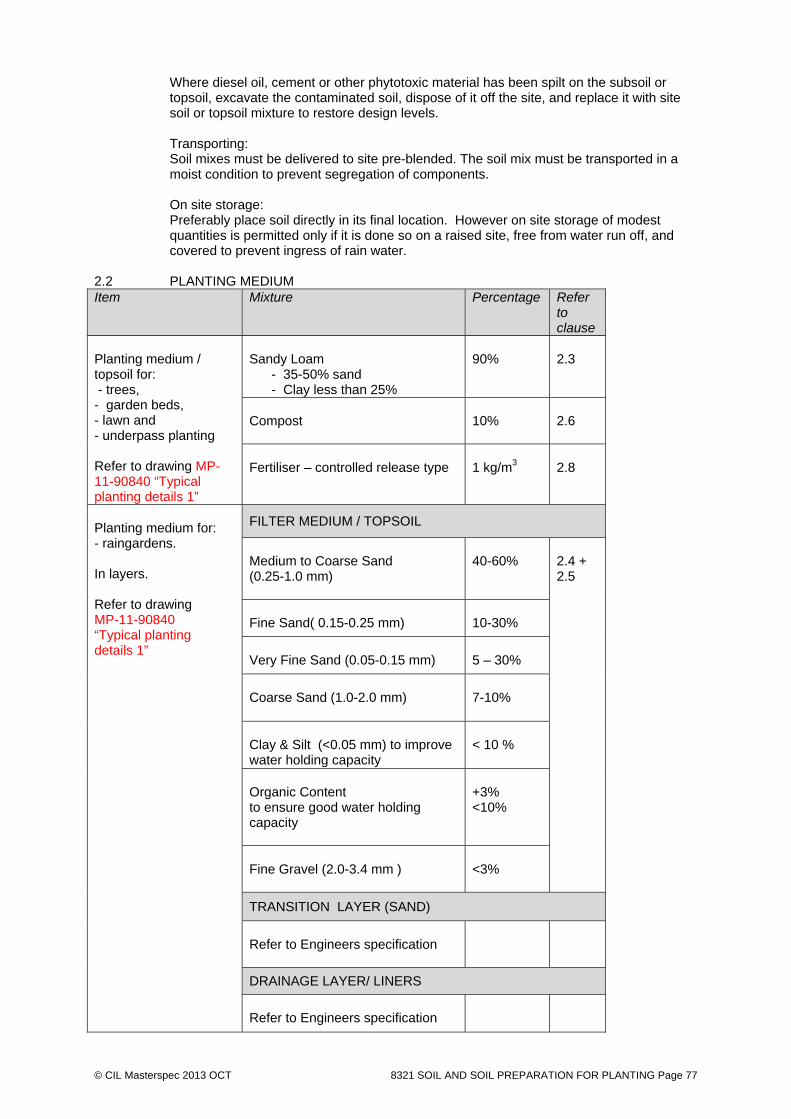
© CIL Masterspec 2013 OCT 8321 SOIL AND SOIL PREPARATION FOR PLANTING Page 77
Where diesel oil, cement or other phytotoxic material has been spilt on the subsoil or topsoil, excavate the contaminated soil, dispose of it off the site, and replace it with site soil or topsoil mixture to restore design levels. Transporting: Soil mixes must be delivered to site pre-blended. The soil mix must be transported in a moist condition to prevent segregation of components. On site storage: Preferably place soil directly in its final location. However on site storage of modest quantities is permitted only if it is done so on a raised site, free from water run off, and covered to prevent ingress of rain water.
2.2 PLANTING MEDIUM Item Mixture Percentage Refer
to clause
Planting medium / topsoil for: - trees, - garden beds, - lawn and - underpass planting Refer to drawing MP-11-90840 “Typical planting details 1”
Sandy Loam - 35-50% sand - Clay less than 25%
90%
2.3
Compost
10%
2.6
Fertiliser – controlled release type
1 kg/m3
2.8
Planting medium for: - raingardens. In layers. Refer to drawing MP-11-90840 “Typical planting details 1”
FILTER MEDIUM / TOPSOIL
Medium to Coarse Sand (0.25-1.0 mm)
40-60%
2.4 + 2.5
Fine Sand( 0.15-0.25 mm)
10-30%
Very Fine Sand (0.05-0.15 mm)
5 – 30%
Coarse Sand (1.0-2.0 mm)
7-10%
Clay & Silt (<0.05 mm) to improve water holding capacity
< 10 %
Organic Content to ensure good water holding capacity
+3% <10%
Fine Gravel (2.0-3.4 mm )
<3%
TRANSITION LAYER (SAND)
Refer to Engineers specification
DRAINAGE LAYER/ LINERS
Refer to Engineers specification

© CIL Masterspec 2013 OCT 8321 SOIL AND SOIL PREPARATION FOR PLANTING Page 78

© CIL Masterspec 2013 OCT 8321 SOIL AND SOIL PREPARATION FOR PLANTING Page 79
Sandy Loam Requirements 2.3 SANDY LOAM REQUIRED PROPERTIES
Import topsoil in accordance with the Soil schedule and the topsoil properties schedule below. Sandy Loam Mix Properties Schedule:
Property Type Soil Mix Amount
Nutrient levels
Phosphorus (P) (mg/L) 10 – 50
Potassium (K) (mg/L) 5 – 15% of CEC
Sulphur (S) (mg/L) > 40 <100
Calcium (Ca) (mg/L)2 60 – 75% of CEC
Sodium (Na) (mg/L) 2 < 5% of CEC
Nitrogen (N) (mg/L) 100
Manganese (Mn) (mg/L) 1 – 15
Carbon:nitrogen ratio < 80:1
Other properties
Organic matter (% by mass) 3 – 15%
Soil reaction (pH) 5.5 – 7.5
Moisture content where clods are easily fractured and soil remains workable
Calcium level to be expressed as a percentage of the cation exchange capacity, where calcium should represent 60-75% of the cation exchange capacity and sodium <5%.
Raingarden Requirements 2.4 HYRAULIC CONDUCTIVITY
Required 100-300mm/hr Note: The hydraulic conductivity of potential filter media should be measured
using the ASTM F1815-06 method.
2.5 RAINGARDEN ADDITIONAL REQUIRED PROPERTIES Import topsoil in accordance with the Soil schedule and the topsoil properties schedule below. i. Total Nitrogen (TN) Content – <1000 mg/kg. ii. Orthophosphate (PO43-) Content – <80 mg/kg. Note: Soils with total phosphorus concentrations >100 mg/kg
should be tested for potential leaching. Where plants with moderate phosphorus sensitivity are to be used, total phosphorus concentrations should be <20 mg/kg.
iii. Organic Matter Content at least 3% (w/w). Note: An organic content lower than 3% is likely to have too
low a water holding capacity to support healthy plant growth. In order to comply with both this and the TN and PO43- content requirements, a low nutrient organic matter will be required.
iv. pH as specified for ‘natural soils and soil blends’ 5.5 – 7.5
(pH 1:5 in water). v. Electrical Conductivity (EC) as specified for ‘natural soils and soil blends’ <1.2 dS/m.

© CIL Masterspec 2013 OCT 8321 SOIL AND SOIL PREPARATION FOR PLANTING Page 80
2.6 COMPOST PROPERTIES Provide well-rotted vegetative material or animal manure, free from harmful chemicals, grass and weed growth. Standard: To AS 4454.
2.7 HERBICIDES Post-emergence selective chemical to control broadleaf weeds and/or a non-selective
chemical. Submit for review the proposed chemical and area of use. 2.8 FERTILISER Provide proprietary fertilisers, delivered to the site in sealed bags marked to show
manufacturer or vendor, weight, fertiliser type, N:P:K ratio, recommended uses and application rates.
2.9 ADDITIVES
Where required in section 3 below apply additives to subsoil after ripping or cultivation and incorporate into the upper 100 mm layer of the subsoil. Description: Gypsum Volume: Incorporate at the rate of 0.25 kg/m2.
2.10 DRAINAGE PIPE
Refer to 7451 SURFACE WATER DRAINAGE for pipe work related to overflow drains and underdrains.
2.11 OVERFLOW
Overflow appropriately sized to the rain garden, and connected to drainage system. 3.9 FILTER FABRIC Proprietary heavy duty geotextile filter fabric made from non-woven polypropylene fibre
(PP). 3. EXECUTION Conditions 3.1 WORK SEQUENCE
Planting shall not begin in any given area until all construction work which would cause damage to new planting has been completed, total weed control is achieved and the Engineer has approved of the final ground shape in accordance with the contract drawings. If planting is not possible due to unfavourable seasonal requirements, the Contractor shall be responsible for maintaining erosion and weed control at his own expense in all planted areas until planting, mulching and weed matting is able to take place.
3.2 DELIVERY Only deliver material to the site that can be immediately placed in its final location from
the delivery vehicle. 3.3 SERVICES Check for services in the area of this work. Avoid interference or damage to them.
Ensure that all new services are in place before commencing work. 3.4 ENSURE Ensure that all areas are clean, ready to be worked and clear of any continuing work by
others. Application 3.5 PREPARATION OF PLANTING AREAS Place in 100mm layers, lightly compacted by heeling or rolling and slightly mounded in
the centre of the bed.

© CIL Masterspec 2013 OCT 8321 SOIL AND SOIL PREPARATION FOR PLANTING Page 81
Thoroughly spray planting areas which contain weed growth with a non-selective
herbicide. Apply using protective clothing, in dry, still-air conditions to the spray manufacturer's requirements. Excavation, shape the subgrade to fall as shown on the Drawings. Cultivate manually within 300 mm of paths, kerbs, footings or other structures to a depth of 150mm. Remove stones exceeding 25 mm, clods of earth exceeding 50 mm, and weeds, rubbish or other deleterious material brought to the surface during cultivation. Trim the compacted surface to design levels after cultivation. Apply additives to subsoil after ripping or cultivation and incorporate into the upper 100 mm layer of the subsoil. Do not destabilise kerbs, gutters and adjacent pavements, edge restraints and structures.
3.6 PREPARATION FOR TREE PLANTING
Excavate tree pits as per drawings Tree pits in hard paved areas shall be drilled using an auger to minimise disturbance to surrounding subgrade. Tree pits in aggregate paving, lawn or garden beds shall be excavated manually or with a backhoe. Excavate tree pits to dimensions as shown on drawings. The pit bases and sides to be broken up by hand to a depth of 150mm to facilitate root penetration, air movement and drainage. Cultivate as required on the drawings manually cultivate subgrade to base and sides of tree pit to a depth of 150mm. Do not disturb services. Do not destabilise kerbs, gutters and adjacent pavements, edge restraints and structures. During cultivation, remove stones exceeding 25mm, clods of earth exceeding 50mm, and any rubbish or other deleterious material brought to the surface during cultivation. Trim the base of tree holes to the required design levels and shapes, after cultivation. Ensure tree pit bases are graded to fall to the subsoil drainage where nominated on the Drawings. Apply additives to subsoil after ripping or cultivation and incorporate into the upper 100 mm layer of the subsoil.
Do not destabilise kerbs, gutters and adjacent pavements, edge restraints and structures.
3.7 PREPARATION OF GRASS AREAS Place in 100mm layers, lightly compacted by heeling or rolling and slightly mounded in
the centre of the bed. Thoroughly spray planting areas which contain weed growth with a non-selective
herbicide. Apply using protective clothing, in dry, still-air conditions to the spray manufacturer's requirements.
Thoroughly spray grass areas which contain weed growth with a non-selective herbicide.
Apply using protective clothing, in dry, still-air conditions to the spray manufacturer's requirements.
Excavation, shape the subgrade to fall as shown on the Drawings. Cultivate manually within 300 mm of paths, kerbs, footings or other structures to a depth of 150mm. Remove stones exceeding 25 mm, clods of earth exceeding 50 mm, and weeds, rubbish or other deleterious material brought to the surface during cultivation. Trim the compacted surface to design levels after cultivation. Apply additives to subsoil after ripping or cultivation and incorporate into the upper 100 mm layer of the subsoil.

© CIL Masterspec 2013 OCT 8321 SOIL AND SOIL PREPARATION FOR PLANTING Page 82
Do not destabilise kerbs, gutters and adjacent pavements, edge restraints and structures 3.8 CONSOLIDATION
Compact lightly and uniformly topsoils in 150 mm layers. Avoid differential subsidence and excess compaction and produce a finished topsoil surface which has the following characteristics:
Finished to design levels. Smooth and free from stones or lumps of soil. Graded to drain freely, without ponding, to catchment points. Graded evenly into adjoining ground surfaces. Ready for mulch and planting.
3.9 TOPSOIL SPREADING
Spread the topsoil on the prepared subsoil and grade evenly, making the necessary allowances to required finished levels and contours may be achieved after light compaction. Spreading: On steep batters, if using a chain drag, ensure there is no danger of batter disturbance. Finishing: Feather edges into adjoining undisturbed ground.
Spread topsoil to the compacted depth as on the drawings Do not place and spread topsoil when the ground or topsoil are excessively wet or in a
condition which would be detrimental to the work. Carry out final grading of the top 100 - 150mm to ensure a true specified level and slope
and to avoid hollows or other depressions where water may collect. Loosen unduly compacted areas (such as in traffic routes) by ripping or discing prior to final levelling.
The final grade shall allow for subsidence so that after settlement the levels shall be the final specified levels. Avoid unnecessary handling of soil. Only handle soil during fine weather. Never handle soil when soil is saturated.
3.10 RAINGARDEN TOPSOL (FILTER MEDIA) INSTALLATION
It is recommended that filter media be lightly compacted during installation to prevent migration of fine particles. In small areas, a single pass with a vibrating plate should be used to compact the filter media, while in large areas, a single pass with roller machinery (e.g. a drum lawn roller) should be performed. Under no circumstance should heavy compaction or multiple-passes be made. Filter media should be installed in 150mm layers. Do not install filter media in wet conditions or when the media itself is wet. Protect all areas of installed soil to prevent any additional compaction during construction.
3.11 FINAL GRADING When topsoil is reasonably dry and workable, grade it to smooth, flowing contours, with
falls, for adequate drainage, removing all minor hollows and ridges. Crown all planter beds to provide a gently rounded profile. 3.12 OVERFLOW DRAIN
Install overflow stand pipe with top above garden level, connect to surface water system. Refer 7451 SURFACE WATER DRAINAGE
3.13 UNDERDRAIN PIPE INSTALLATION Install underdrain pipe with the aggregate at the lower level, wrap end in filter fabric and lay to fall and connect to surface water system. Refer 7451 SURFACE WATER DRAINAGE.

© CIL Masterspec 2013 OCT 8321 SOIL AND SOIL PREPARATION FOR PLANTING Page 83
3.14 LAY DRAINAGE AGGREGATE Place aggregate from a low level and spread manually, do not compact. 3.15 LAY FILTER FABRIC Lay fabric over the drainage gravel and along any walls of the garden. Overlap edges
minimum 150mm along all edges. 3.16 PROTECTION
Protect freshly laid soil from any adjacent site works. Exclude any activity which may result in soil compaction and/or contamination. This includes walking or standing on freshly laid soil. No vehicles are to cross newly placed soil and/or completed garden areas. Should pedestrian access across a completed garden bed or rain garden be necessary suitable measures must be taken to ensure no compaction occurs.
Completion 3.17 CLEAN UP Clean up and remove surplus soil from the site. 3.18 REMOVE Remove debris, unused materials and elements from the site. 4. SELECTIONS 4.1 SOIL SCHEDULE Refer to Requirements above
END OF SECTION
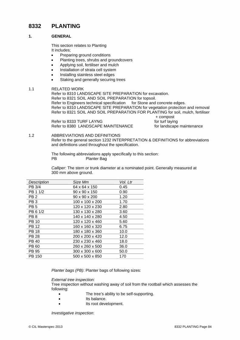
© CIL Masterspec 2013 8332 PLANTING Page 84
8332 PLANTING 1. GENERAL This section relates to Planting It includes;
Preparing ground conditions Planting trees, shrubs and groundcovers Applying soil, fertiliser and mulch Installation of strata cell system Installing stainless steel edges Staking and generally securing trees
1.1 RELATED WORK Refer to 8310 LANDSCAPE SITE PREPARATION for excavation. Refer to 8321 SOIL AND SOIL PREPARATION for topsoil. Refer to Engineers technical specification for Stone and concrete edges.
Refer to 8310 LANDSCAPE SITE PREPARATION for vegetation protection and removal Refer to 8321 SOIL AND SOIL PREPARATION FOR PLANTING for soil, mulch, fertiliser + compost
Refer to 8333 TURF LAYNG for turf laying Refer to 8380 LANDSCAPE MAINTENANCE for landscape maintenance
1.2 ABBREVIATIONS AND DEFINITIONS Refer to the general section 1232 INTERPRETATION & DEFINITIONS for abbreviations
and definitions used throughout the specification.
The following abbreviations apply specifically to this section: PB Planter Bag Calliper: The stem or trunk diameter at a nominated point. Generally measured at 300 mm above ground.
Description Size Mm Vol. Ltr PB 3/4 64 x 64 x 150 0.45 PB 1 1/2 90 x 90 x 150 0.90 PB 2 90 x 90 x 200 1.20 PB 3 100 x 100 x 200 1.70 PB 5 120 x 120 x 230 2.80 PB 6 1/2 130 x 130 x 280 3.60 PB 8 140 x 140 x 280 4.50 PB 10 120 x 120 x 460 5.60 PB 12 160 x 160 x 320 6.75 PB 18 180 x 180 x 360 10.0 PB 28 200 x 200 x 420 12.0 PB 40 230 x 230 x 460 18.0 PB 60 260 x 260 x 500 36.0 PB 95 300 x 300 x 600 50.0 PB 150 500 x 500 x 850 170
Planter bags (PB): Planter bags of following sizes: External tree inspection: Tree inspection without washing away of soil from the rootball which assesses the following:
The tree’s ability to be self-supporting. Its balance. Its root development.
Investigative inspection:

© CIL Masterspec 2013 8332 PLANTING Page 85
Any method of root inspection that involves the washing away of all or portions of the soil from the rootball to expose a section or all the roots. Destructive inspection: The washing away of all soil from a rootball to allow inspection of rootball development. Where inspection is destructive, trees will be sacrificed. The trees sacrificed should be in addition to the number of trees ordered. Partial inspection: A method of exposing a section of a root system to enable inspection of root development by washing the soil away in a wedge-shaped section from the stem to the extremity of the rootball. This soil can be gently replaced so the tree is not damaged. Health: Supply plants with foliage size, texture and colour at time of delivery consistent with the size, texture and colour shown in healthy specimens of the nominated species. Vigour: Supply plants with extension growth consistent with that exhibited in vigorous specimens of the species nominated.
Documents 1.3 DOCUMENTS Refer to the general section 1233 REFERENCED DOCUMENTS. The following
documents are specifically referred to in this section: NZS 4454 Composts, Soil Conditioners and Mulches 1.4 SUPPLIER DOCUMENTS Supplier's documents relating to this part of the work:
Completed tree form and certification of source Supplier contact details Tree have been Client procured at selected nurseries for specific tree species. The
Contractor is to contact the Engineer for confirmation of Nursery + trees. Warranties 1.5 WARRANTY Provide warranty for: 05 years: For all trees 05 years Structural cell system Provide the warranty in the standard form in the general section 1237WA WARRANT
AGREEMENT. Commence the warranty from the date of practical completion of the contract works. Requirements 1.6 QUALIFICATIONS Landscape contractors to be experienced, competent landscapers familiar with the
materials and techniques specified. 1.7 ACCEPTABLE PRODUCT SUPPLIERS Where a product supplier is named in SELECTIONS, the product must be provided by the
named supplier. Where more than one named supplier, any one of the named suppliers will be acceptable.
1.8 NO SUBSTITUTIONS Substitutions are not permitted to any of the products listed in this section.

© CIL Masterspec 2013 8332 PLANTING Page 86
1.9 SAMPLES
Submit representative samples of each material, packed to prevent contamination and labelled to indicate source and content.
Item Quantity + Comment
All trees
All trees to be available at nursery for inspection by LA and tagging for use on site. Contractor to coordinate the availability of tree species for inspection to a standard as per the specification to ensure that all trees can be tagged within a singular 1 day nursery visit by Landscape Architect. Any additional visit to the nursery by Landscape Architect to this will be at the cost of the Contractor.
All plants
1 plant sample for each 100 (or part thereof) of each species or variety, in the condition in which it is proposed to supply that plant to the site.
MULCH Organic Twig Mulch 0.5 kg bag for each type
Free of fines Limestone Aggregate Mulch 0.5 kg bag for each type
Free of fines River stone Aggregate
0.5 kg bag for each type Free of fines
EDGE RESTRAINTS KCss Stainless steel edge restraint
1m length
GBss Garden bed stainless steel edge restraint
1m length
TRss Tree pit stainless steel edge restraint
1m length
OTHER Trees stakes 1 # stake
Root barrier 1# sample (min 200mm x 200mm)
Quality control and assurance 1.10 INSPECTIONS
Give notice so inspection may be made of the following: Setting out completed. Plant holes excavated and prepared for planting. Tree pits excavated and prepared for cell placement. Tree pits cell placement with soil placement + prior to basecourse
placement. Placement of SS edges prior to final fix Plant material set out before planting. Final tree position prior to planting Planting, staking and tying completed. Completion of planting establishment work. Selected trees at nursery

© CIL Masterspec 2013 8332 PLANTING Page 87
1.11 IDENTITY Plants to be good and true representatives of their species, cultivar or variety and each
batch shall be labelled. 1.12 LABELLING Attach legible labels to each plant delivered to site as a separate unit, or to each box,
bundle or bale containing plants. The labels shall give the approved botanical name, size, age and quantity and other information required to identify the plant or plants.
1.13 PLANTER BAGS UV stabilised black plastic planter bags (PB). Standard bag sizes range from PB3 to
PB150. Plant sizes are specified by PB bag size (pint bag) up to PB150. Thereafter specimen trees may be specified by bag size, girth or height or a combination of these.
1.14 HEALTH Ensure plants are free of pests, diseases, disorders, disfiguring knots damage or pruning
injury. 1.15 RESPONSIBILITY FOR CONTINUED SURVIVAL, HEALTH AND GROWTH The Contractor is responsible for the survival, good health and adequate growth of plants
connected with this contract during transportation, storage or when planted on the site during the contract and maintenance period.
Replace any plants which die, are significantly damaged, or which show signs of
significant stress or declining health during the contract and maintenance period. Plants destroyed by vandalism by others or theft once planted are excluded from this condition.
Weed Control 1.16 WEED CONTROL Use Chemical Herbicides with caution. They shall conform in every respect to the
mixture required and be applied strictly in accordance with the manufacturer’s instructions. Do not spray herbicide in windy conditions. Make good any damage caused by excess spray drift.
All chemical herbicides used are to be non-toxic to human beings, birds and animals
under normal use and only those chemical herbicides registered under the Pesticides Act may be used.
Where a translocated herbicide such as glyphosate is used around plants in leaf, an adequate guard must be used for all spraying.
Carefully calibrate all spraying equipment to prevent under or over dosing. Replace any
plants damaged by misplaced herbicide. No herbicide containers, empty or full, are to be left on site at any time.
Cultivation 1.17 CULTIVATION OF PLANTING AREAS Cultivate planting areas to a depth as shown on the drawings to form a firm and friable
tilth suitable for pit planting by hand. During cultivations remove all weed including weed root off site. Grade to smoothly flowing or even contours to the finished levels by hand or machine as
necessary. 1.18 STONE/DEBRIS PICKING After cultivating remove all stones, grass sods and other debris larger than 75mm in any
dimension and all roots in excess of 15mm diameter or 200mm length.

© CIL Masterspec 2013 8332 PLANTING Page 88
2. PRODUCTS Materials 2.1 CONTAINER GROWN SHRUBS AND GRASSES Container grown shrubs to be strong well-rooted sturdy plants, without stakes or canes,
with two or three main stems and a good bushy form. They must have been grown in the containers for at least 6 months over a summer period prior to planting out. The container shall be full of root but not root bound. Recently 'Containerised' or 'bagged up' plants will not be accepted.
Plants shall not have been grown in the container for longer than 12 months without
having been potted on.
Characteristics: Provide plants with the following characteristics:
Large healthy root systems, with no evidence of root curl, restriction or damage.
Vigorous, well established, free from disease and pests, of good form consistent with the species or variety.
Hardened off, not soft or forced, and suitable for planting in the natural climatic conditions prevailing at the site.
Other Characteristics as described in this section. Supply only plants that:
Are free from injury. Are self-supporting. Have the calliper at any given point on the stem greater than the
calliper at any higher point on the stem. 2.2 TREES Tree species to have a single well defined leader and a reasonably straight main stem
which is sturdy enough to easily support the crown of the tree under the environmental and climatic conditions of the planting site. Characteristics: Provide trees with the following characteristics:
Provide trees which, unless required to be multi-stemmed, have a single leading shoot.
Large healthy root systems, with no evidence of root curl, restriction or damage.
Vigorous, well established, free from disease and pests, of good form consistent with the species or variety.
Hardened off, not soft or forced, and suitable for planting in the natural climatic conditions prevailing at the site.
Other Characteristics as described in this section. Supply only plants that:
Are free from injury. Are self-supporting. Have the calliper at any given point on the stem greater than the
calliper at any higher point on the stem. Species with an excurrent form: Supply trees with a defined central leader and the apical bud intact. Crown symmetry and distribution: Difference on opposite sides of the stem axis < 20%. Stem structure: Species with excurrent form:

© CIL Masterspec 2013 8332 PLANTING Page 89
Supply trees with a single stem roughly in the centre of the tree with any deviation from vertical < 15º.
Species with decurrent form: Supply trees where the central stem is not divided at any point lower than the clean stem height nominated, and that the stem junction at the point of division is sound.
All species: Ensure that branch diameter is less than or equal to one-half of the calliper immediately above the branch junction.
Included bark: trees where the branch/stem bark ridges at junctions between stems and branches and between co-dominant stems are convex, except for species prone to include bark that are known to remain strong. Trunk position: Supply trees with the distance from the centre of the trunk to the extremity of the rootball not varying by > 10%. Compatibility of graft unions: Supply trees where the union between the scion and rootstock is sound for the entire perimeter of the graft, and the diameter of the scion immediately above the graft is equal to the diameter of the rootstock immediately below the graft (± 20%).
2.3 ROOT SYSTEMS All plants to have good, vigorous, fibrous root systems in keeping with the normal rooting
habit of the species. Root balls and container growing medium shall be free from perennial weed and soil borne plant diseases.
Root direction: Ensure that roots, from the point of initiation, generally grow in an outwards (radial) or downwards direction, and that any deviation from the established direction < 45º.
Trees with a calliper at ground level < 40 mm: Ensure that the diameter of any nonconforming roots at the extremity of the rootball < 25% of the calliper.
Trees with a calliper at ground level 40 mm: Ensure that the diameter of any nonconforming roots at the extremity of the rootball < 10 mm.
Soil retention: On shaking or handling the unsupported rootball at least 90% of the soil volume to remain intact.
Height of root crown: ensure that root crown is at the surface of the rootball.
2.4 BRANCH SYSTEMS Plants to have well developed vigorous branch systems of normal habit, dimensions and
density for a well grown nursery plant of their species. Plants which have 'leggy', narrow or thin branch systems will not be accepted.
2.5 PEST AND DISEASE
Supply plants with foliage free from attack by pests or disease. Native species with a history of attack by native pests: Restrict evidence of previous attack to < 15% of the foliage and ensure absence of actively feeding insects.
2.6 HARDINESS Plants to be fully hardy having been acclimatized in the nursery to sun, exposure and
cold. Plants which have not been hardened off, drawn plants with soft growth or plants requiring additional support to that specified will not be accepted.
2.7 DRYING OUT Plants which have dried out or show signs of desiccation or wilting will not be accepted.
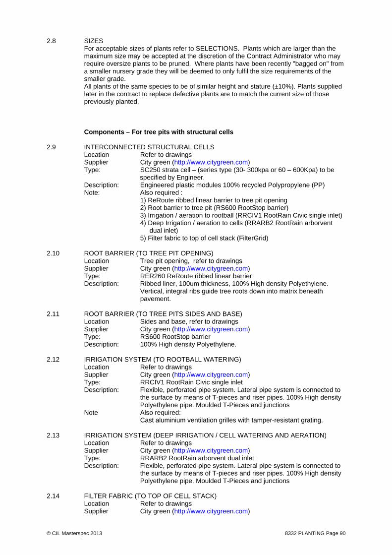
© CIL Masterspec 2013 8332 PLANTING Page 90
2.8 SIZES For acceptable sizes of plants refer to SELECTIONS. Plants which are larger than the
maximum size may be accepted at the discretion of the Contract Administrator who may require oversize plants to be pruned. Where plants have been recently "bagged on" from a smaller nursery grade they will be deemed to only fulfil the size requirements of the smaller grade.
All plants of the same species to be of similar height and stature (±10%). Plants supplied later in the contract to replace defective plants are to match the current size of those previously planted.
Components – For tree pits with structural cells 2.9 INTERCONNECTED STRUCTURAL CELLS
Location Refer to drawings Supplier City green (http://www.citygreen.com) Type: SC250 strata cell – (series type (30- 300kpa or 60 – 600Kpa) to be
specified by Engineer. Description: Engineered plastic modules 100% recycled Polypropylene (PP) Note: Also required : 1) ReRoute ribbed linear barrier to tree pit opening 2) Root barrier to tree pit (RS600 RootStop barrier)
3) Irrigation / aeration to rootball (RRCIV1 RootRain Civic single inlet) 4) Deep Irrigation / aeration to cells (RRARB2 RootRain arborvent
dual inlet) 5) Filter fabric to top of cell stack (FilterGrid)
2.10 ROOT BARRIER (TO TREE PIT OPENING)
Location Tree pit opening, refer to drawings Supplier City green (http://www.citygreen.com) Type: RER260 ReRoute ribbed linear barrier Description: Ribbed liner, 100um thickness, 100% High density Polyethylene.
Vertical, integral ribs guide tree roots down into matrix beneath pavement.
2.11 ROOT BARRIER (TO TREE PITS SIDES AND BASE) Location Sides and base, refer to drawings
Supplier City green (http://www.citygreen.com) Type: RS600 RootStop barrier Description: 100% High density Polyethylene.
2.12 IRRIGATION SYSTEM (TO ROOTBALL WATERING) Location Refer to drawings Supplier City green (http://www.citygreen.com) Type: RRCIV1 RootRain Civic single inlet Description: Flexible, perforated pipe system. Lateral pipe system is connected to
the surface by means of T-pieces and riser pipes. 100% High density Polyethylene pipe. Moulded T-Pieces and junctions
Note Also required: Cast aluminium ventilation grilles with tamper-resistant grating.
2.13 IRRIGATION SYSTEM (DEEP IRRIGATION / CELL WATERING AND AERATION) Location Refer to drawings Supplier City green (http://www.citygreen.com) Type: RRARB2 RootRain arborvent dual inlet Description: Flexible, perforated pipe system. Lateral pipe system is connected to
the surface by means of T-pieces and riser pipes. 100% High density Polyethylene pipe. Moulded T-Pieces and junctions
2.14 FILTER FABRIC (TO TOP OF CELL STACK)
Location Refer to drawings Supplier City green (http://www.citygreen.com)
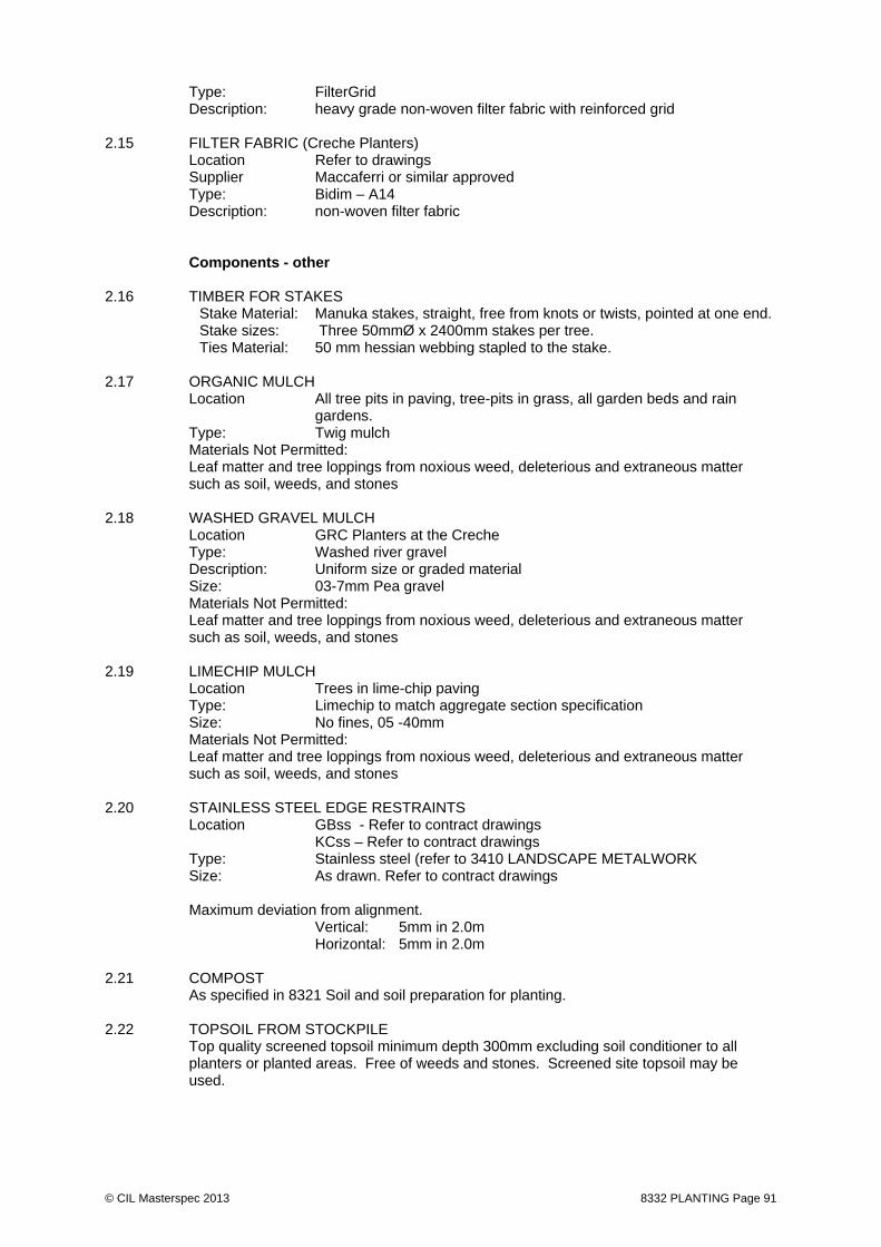
© CIL Masterspec 2013 8332 PLANTING Page 91
Type: FilterGrid Description: heavy grade non-woven filter fabric with reinforced grid
2.15 FILTER FABRIC (Creche Planters) Location Refer to drawings Supplier Maccaferri or similar approved Type: Bidim – A14 Description: non-woven filter fabric
Components - other
2.16 TIMBER FOR STAKES
Stake Material: Manuka stakes, straight, free from knots or twists, pointed at one end. Stake sizes: Three 50mmØ x 2400mm stakes per tree. Ties Material: 50 mm hessian webbing stapled to the stake.
2.17 ORGANIC MULCH Location All tree pits in paving, tree-pits in grass, all garden beds and rain
gardens. Type: Twig mulch Materials Not Permitted: Leaf matter and tree loppings from noxious weed, deleterious and extraneous matter
such as soil, weeds, and stones
2.18 WASHED GRAVEL MULCH Location GRC Planters at the Creche
Type: Washed river gravel Description: Uniform size or graded material Size: 03-7mm Pea gravel Materials Not Permitted: Leaf matter and tree loppings from noxious weed, deleterious and extraneous matter
such as soil, weeds, and stones
2.19 LIMECHIP MULCH Location Trees in lime-chip paving
Type: Limechip to match aggregate section specification Size: No fines, 05 -40mm Materials Not Permitted: Leaf matter and tree loppings from noxious weed, deleterious and extraneous matter
such as soil, weeds, and stones 2.20 STAINLESS STEEL EDGE RESTRAINTS Location GBss - Refer to contract drawings KCss – Refer to contract drawings Type: Stainless steel (refer to 3410 LANDSCAPE METALWORK Size: As drawn. Refer to contract drawings Maximum deviation from alignment. Vertical: 5mm in 2.0m Horizontal: 5mm in 2.0m 2.21 COMPOST As specified in 8321 Soil and soil preparation for planting. 2.22 TOPSOIL FROM STOCKPILE Top quality screened topsoil minimum depth 300mm excluding soil conditioner to all
planters or planted areas. Free of weeds and stones. Screened site topsoil may be used.

© CIL Masterspec 2013 8332 PLANTING Page 92
2.23 FERTILISER FOR PLANTING Well-balanced 6 month slow release fertiliser including available nitrogen, phosphorus
and potassium plus magnesium and trace elements. Fertiliser in granular form to allow distribution through the backfill mix.
Apply slow release fertiliser at a rate of 100g per specimen tree and mixed evenly with
the backfill mix. 2.24 WATERING TUBES Watering tubes shall be 65mm diameter perforated HDPE pipe installed across the base
of the tree pit and up the side to extend 100mm above the finished ground level.

© CIL Masterspec 2013 8332 PLANTING Page 93
3. EXECUTION Conditions 3.1 DELIVERY, STORAGE AND HANDLING
The Contractor shall be responsible for arranging time of plant delivery to the site at which time the plants become the full responsibility of the Contractor. Acceptance of plants on site shall mean that the Contractor is satisfied that the quality of the plants meets the following specifications for quality. The landscape architect shall be informed immediately of any plants that do not meet this standard. The nominated plant supplier will be responsible for the supply, unloading, placement of plants to the site, at suitable times as arranged by the Contractor. The Contractor will be responsible for the care of the plants as soon as they are accepted on arrival at the site. Larger material, such as trees, shall have individual root balls wrapped in polythene to retain humidity. Container grown plants shall not be bundled. The Contractor shall confirm that the proposed method for preparation, lifting on to pallets, loading, transport and delivery to site of advanced plants is compatible with the Contractors method for storage. In the event that the plants are not acceptable to the Contractor and the Landscape Architect they will be rejected in writing, to be replaced.
Take delivery of materials and goods and store on site and protect from damage. Cover plants during transportation. Plant roots shall be protected at all times from sun or
drying winds. Plants that cannot be planted immediately on delivery shall be kept in the shade, well protected, with soil well watered.
Any damage to roots and limbs and damage to the main super structure may result in the rejection of the plant. Plants with damaged growing points, lop sided growth or other deformities may also be rejected at the discretion of the Landscape Architect. If major damage occurs the plants shall be replaced at the Contractor's expense.
Pots and other protective materials shall not be removed until immediately prior to
planting, and shall be disposed of off the site after planting. Roots shall not be left uncovered at any time. Any plants that, in the opinion of the Landscape Architect and Contractor, are found to be root bound or defective in any way when they are removed from their containers, shall be set aside and brought to the attention of the Engineer for action.
3.2 APPROVAL Do not start preparation or planting until the setting out has been inspected and approved
by the Contract Administrator. 3.3 PRE-INSTALLATION REQUIREMENTS Prepare all planting areas indicated on the drawings including clearing out, controlling
weeds, forming new planters, cultivating, and adding soil conditioner, fertiliser and bark mulch.
3.4 TIMING OF OPERATIONS
Work shall only be undertaken when the weather is suitable, i.e. mild, still, overcast and moist, and when the ground is moist and workable. All planting operations shall be suspended during periods of severe frosts, drought, waterlogging or persistent drying winds. Grass seeding shall take place following final sealing of surrounding areas unless otherwise directed by the Engineer. Trees shall be planted prior to the commencement of grass seeding. The Principal shall accept liability for plant deaths greater than 5% where the Contractor has been instructed to proceed with planting outside the normally recognised horticultural season.
3.5 CLEAN OUT PLANTER AREAS Remove weeds, unwanted plants, stumps, rubbish, and excess earth.

© CIL Masterspec 2013 8332 PLANTING Page 94
3.6 PROTECT EXISTING PLANTING TO BE RETAINED Protect plants that are indicated on the plans to be retained. Make good any damage,
including replacement where necessary. 3.7 TEND EXISTING PLANTING TO BE RETAINED Tend any plants that are indicated on the plans to be retained. This includes removing
dead branches and pruning or cutting back so that plants are compact, tidy in appearance, healthy, and of the required size and shape.
3.8 TOPSOIL Supply and install topsoil to planting areas to achieve finished surface levels, and to
ensure specified topsoil depths are achieved. Remove existing earth where necessary to accommodate topsoil and soil conditioner in planters to achieve finished surface levels.
3.9 SOIL CULTIVATION AND CONDITIONER Supply and incorporate soil conditioner to all planting areas where indicated on the plans
at the rate of 0.075m³ per m² (75mm depth) worked into the top 150mm of existing soil. 3.10 FINISHED SURFACE LEVELS The finished surface soil level including soil conditioner (but excluding mulch) shall be
50mm higher than adjacent kerb or lawn areas in the middle of the planter, but shall be graded so that the finished level at the outside of the planting areas is 50mm lower than the adjoining kerb or lawn.
3.11 MARKING & DIMENSIONS Set out the outlines of seeding, turfing and planting areas. Use sand, paint or short
canes close enough together to accurately define the shapes on the ground. Installation/application – structural cells 3.12 EXCAVATION FOR STRUCTURAL CELLS Installer to excavate the tree pit accurately to the dimensions of the detailed plans,
allowing 200mm (8”) additional clearance in length and width. Side walls of excavated pit to be clean, straight, and within 15° of vertical. Tree pit length, width and diagonals at base of pit to be measured to ensure that correct dimensions are being obtained (measurements shown on tree pit detail plus 200mm). Installer to confirm that correct depth has been provided, measuring from finished pavement level, including any drainage layers. Base of tree pit should be flat unless there is a drainage layer to be provided, in which case the subgrade surface must have a grade of 5%.
3.13 REINFORCING COLLAR FOR STRUCTURAL CELLS The top perimeter of the tree pit must be further excavated to a depth of 300mm (12”) and
to a width of 200mm (10”), or a width sufficient to permit a narrow foot compacting plate (reinforcing collar) to be installed. Sides and base of this excavation must be clean and straight.
3.14 DRAINAGE Refer to drawings. Cover top and sides of gravel drainage with a proprietary non-woven filter fabric to
engineer specifications and ensure the sides of the drainage layer are compacted against the sides of the excavation to the density specified.
3.15 SUB-BASE PREPARATION Installer to check CBR of the subgrade below the proposed granular pavement layers to
ensure it meets the applicable pavement design criteria. If the subgrade is fill confirm that it is compacted to a minimum of 95% of maximum dry density at optimum moisture content in accordance with ASTM D 698 Standard Proctor Method.
3.16 INTERCONNECTED STRUCTURAL SOIL CELL ASSEMBLY Refer to supplier installation specification.

© CIL Masterspec 2013 8332 PLANTING Page 95
3.17 ROOTTRAIN IRRIGATION / AERATION PIPE Refer to supplier installation specification. Open ends of pipes to be sealed with Cast aluminium ventilation grilles with tamper-
resistant grating. 3.18 ROOT BARRIERS (ROOT STOP) Refer to supplier installation specification. 3.19 LOADING MATRIX WITH FILLER SOIL Ensure that all required filler soil testing and certification is complete to the satisfaction of
the Landscape Architect prior to loading into the tree pit. When matrix is fully assembled, with all specified piping and barriers in place, the filler
soil can be loaded into the matrix. Soil should be placed in the matrix using an excavator bucket and spread with rakes or shovels until the void spaces are filled. Ensure the outer trench for the reinforcing collar is kept clean and free of filler soil. Matrix is to be vibrated using plate vibration or needle vibration equipment in order to shake soil into all voids.
Continue loading dry soil, raking out and vibrating, until matrix is filled. Should the filler soil constituents and moisture content not permit the voids to be fully
filled, assemble the structural soil cell modules in layers and progressively fill, layer by layer.
Note: In some instances an air layer is detailed in the top of the matrix. In this case soil is loaded, spread and vibrated in smaller amounts, to ensure an even distribution of soil beneath the air layer.
3.20 FILTER FABRIC Refer to supplier installation specification. 3.21 COMPACTION AND PAVEMENT LAYERS Reinforcing collar Load the granular base course material into the base of the collar trench ensuring the
geocomposite layer is not displaced from the base of the trench. Compact the granular material in 150mm (6”) lifts until the collar is level with the top of the matrix.
Tree pit opening Confirm the exact required position of the tree pit opening from project details and with
reference to survey markers. Cut geocomposite layer and fold back to expose the tree pit opening. Position form-work to provide for poured concrete system, or other method as specified in project details. Place linear ribbed root barrier within the tree pit opening with vertical ribs facing inwards. Ensure bottom edge of barrier is placed on the structural soil cell matrix and upper edge is at finished pavement level. Trim to suit with sharp knife. Ensure any joins are overlapped a minimum of 150mm (6”), are clean and dry and taped both sides with external grade, moisture resistant, adhesive tape.
Granular base course Load and spread granular base course material onto the geocomposite layer in an even
depth of 100mm (4”). Compact this layer with a vibrating plate compactor with a mass of 1200kg – 1400kg/m² of base plate, to specified compaction levels. Continue building compacted granular layers to required levels including the reinforcing collar.
Installation/application – all planting (refer above to structural cells 3.22 SETTING OUT
Planting positions shall be pegged/laid out, in accordance with the planting plan and plant schedule. Where locations of individual plants are not shown, space at an even spacing in staggered rows across the plant bed indicated.

© CIL Masterspec 2013 8332 PLANTING Page 96
The Landscape Architect may require minor refinement to the design with adjustments to lines, levels and grouping of trees/shrubs/reeds locally as the planting proceeds requiring the Contractor's co-operation and agreement. In areas of block planting, plants shall be spaced evenly so that when established they will completely fill the areas indicated as precisely as possible. The extent of the area to be filled by each species shall first be defined by plants spaced around the perimeter. The remaining plants shall then be used to fill the centre of the area in an informal manner avoiding straight lines and regular geometric patterns. The Contractor shall not commence planting until the setting out has been inspected and approved. If work is carried out without the prior approval, realignment and reseting may be necessary at the Contractor's expense.
3.23 PLANT LAYOUT Place and plant at the same density throughout that species area, group or drift. Do not
plant in regular rows unless this is shown on the drawings. Pay particular attention to the distribution of plants around the perimeter of areas to ensure they are evenly spaced and that the front row of plants follows the shape of the area.
3.24 CURVED EDGES Achieve a smooth and even curve when setting out curved edges and outlines of planting
next to grass or hard surfaces. The first row of plants in the planting area is to exactly follow this curve at a constant distance behind it.
3.25 MAINTAINING MARKINGS Keep all setting out visible until planting has been finished. 3.26 PIT SIZE Dig the planting pit large enough to allow the root-ball of plants to be accommodated
without distortion or, in the case of bare root/open ground plants, for their roots to be fully spread. Do not distort or bend roots to fit into the planting pit.
3.27 PRUNING Prune any damaged or diseased roots and branches. 3.28 PLANT POSITIONING Place plants in the centre of the planting pit with their main stem vertical and at such a
depth that the firmed down soil after planting is at the same height as the nursery ground level or the container soil level.
Pierce the bottom of each hole to a depth of 200mm with the tines of a fork or similar implement to ensure root penetration and free drainage. Roughen the sides of pits dug by rotary augers.
The base of each hole shall be provided with a 25mm layer of proprietary compost. Apply
fertiliser to the base of the dug hole. Remove container from container grown plants immediately prior to planting. Take care
to ensure that the root ball is not disturbed during container removal or planting. Set plants in their final positions with main stem vertical and at such a depth that the soil,
when firmed down is at the same height as the nursery earth marks on the stem or the container soil level. Spread out loose roots in a natural fashion, carefully place the soil under and amongst them to fill all voids and firmed in.
3.29 BACKFILL Back fill with finely broken down topsoil free from clay lumps and large clods and
thoroughly mixed with slow release planting fertiliser. Spreading of planting fertiliser on the soil surface after planting will not be accepted.
3.30 TWIG PULL TEST It should not be possible to lift or disturb the roots of a properly firmed plant by pulling on
leaves or un-lignified shoots.
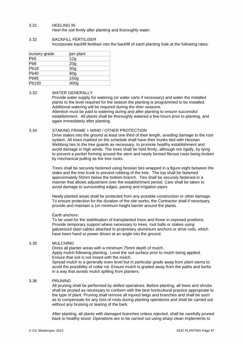
© CIL Masterspec 2013 8332 PLANTING Page 97
3.31 HEELING IN Heel the soil firmly after planting and thoroughly water. 3.32 BACKFILL FERTILISER Incorporate backfill fertiliser into the backfill of each planting hole at the following rates: nursery grade per plant Pb5 12g Pb8 20g Pb18 40g Pb40 60g Pb95 150g Pb150 400g 3.33 WATER GENERALLY Provide water supply for watering (or water carts if necessary) and water the installed
plants to the level required for the season the planting is programmed to be installed. Additional watering will be required during the drier seasons.
Attention must be paid to watering during and after planting to ensure successful establishment. All plants shall be thoroughly watered a few hours prior to planting, and again immediately after planting.
3.34 STAKING FRAME + WIND / OTHER PROTECTION
Drive stakes into the ground at least one third of their length, avoiding damage to the root system. All trees marked on the schedule shall have their trunks tied with Hessian Webbing ties to the tree guards as necessary, to promote healthy establishment and avoid damage in high winds. The trees shall be held firmly, although not rigidly, by tying to prevent a pocket forming around the stem and newly formed fibrous roots being broken by mechanical pulling as the tree rocks. Trees shall be securely fastened using hessian ties wrapped in a figure eight between the stake and the tree trunk to prevent rubbing of the tree. The top shall be fastened approximately 50mm below the bottom branch. Ties shall be securely fastened in a manner that allows adjustment over the establishment period. Care shall be taken to avoid damage to surrounding edges, paving and irrigation pipes. Newly planted areas shall be protected from any possible construction or other damage. To ensure protection for the duration of the site works, the Contractor shall if necessary, provide and maintain a 1m minimum height barrier around the plants. Earth anchors: To be used for the stabilisation of transplanted trees and those in exposed positions. Provide temporary support where necessary to trees, root balls or stakes using galvanized steel cables attached to proprietary aluminium anchors or drive rods, which have been hand or power driven at an angle into the ground.
3.35 MULCHING Dress all planter areas with a minimum 75mm depth of mulch. Apply mulch following planting. Level the soil surface prior to mulch being applied. Ensure that soil is not mixed with the mulch. Spread mulch to a generally even level but in particular grade away from plant stems to avoid the possibility of collar rot. Ensure mulch is graded away from the paths and kerbs in a way that avoids mulch spilling from planters.
3.36 PRUNING All pruning shall be performed by skilled operatives. Before planting, all trees and shrubs shall be pruned as necessary to conform with the best horticultural practice appropriate to the type of plant. Pruning shall remove all injured twigs and branches and shall be such as to compensate for any loss of roots during planting operations and shall be carried out without any bruising or tearing of the bark. After planting, all plants with damaged branches unless rejected, shall be carefully pruned back to healthy wood. Operations are to be carried out using sharp clean implements to

© CIL Masterspec 2013 8332 PLANTING Page 98
give a clean sloping cut with one flat face. Ragged edges of bark or wood are to be trimmed with a sharp knife. All pruning’s shall be removed from site.
3.37 WATERING
Thoroughly water the plants before planting, immediately after planting, and as required to maintain growth rates free of stress. Adjust irrigation system as required to provide required amounts and frequency of watering. An trickle irrigation system is to be installed on this site for new tree planting. The Contractor shall ensure that the system is fully operational at all times. Should the system fail to operate for whatever reason the Contractor shall be required to provide manual watering until the irrigation system is fully operational. Attention must be paid to watering during and after planting to ensure successful establishment. Notwithstanding any prevailing restrictions by the local authority on the use of water for watering any plants, the Contractor shall be deemed totally responsible for making any special arrangements which may be necessary to ensure regular and adequate watering of trees and shrubs to ensure successful establishment. In the interests of good horticultural practice watering shall be sufficient to give 300mm minimum depth penetration and not just surface dampening. The Contractor shall bring to the site sufficient water carts, hoses and sprinklers to provide an adequate water supply to the plant material. Prior to Planting: - All plants, shall be thoroughly watered a few hours prior to planting. After Planting: - At the time of planting all trees and shrubs are to be copiously watered in such a way that the entire tree pit or shrub station is moistened to field capacity to encourage settlement. The Contractor shall be responsible for watering all plants as required to ensure their survival. Drought Conditions: - Lack of availability of water shall not release the Contractor from his obligation to replace all dead or dying plants at the end of the first season of growth after planting. The price submitted shall allow for adequate watering and, when not directed, the Engineer shall not need to remind the Contractor of his obligation during periods of drought. If water supply is likely to be restricted, inform the Engineer without delay and ascertain availability and cost of water from another approved source.
Completion 3.38 ROUTINE CLEANING Carry out routine trade cleaning of this part of the work including periodic removal of all
debris, unused materials and elements from the site. 3.39 DEFECTIVE OR DAMAGED WORK All plants shall be maintained for two full growing seasons after planting. Replace
damaged or marked plants during this period. 3.40 PROTECTION Provide the following temporary protection of the finished work: - As required to allow plant establishment and at the direction of the Landscape
Architect 4. SELECTIONS Materials 4.1 PLANTING SCHEDULE Refer to the planting schedules in the SCHEDULES section of this specification 4.2 STRUCTURAL CELL SYSTEM Refer to PRODUCTS of this section and the contract drawings.

© CIL Masterspec 2013 8332 PLANTING Page 99
4.3 PLANTING HARDWARE (INCLLUDING STEEL EDGES) Refer to Contract drawings for materials size/ dimensions Refer to PRODUCTS section above Spares and maintenance materials 4.4 SPARES AND MAINTENANCE MATERIALS Provide the following spares and maintenance materials: Item/quantity: Maintenance manual Deliver to: Engineer prior to practicable completion.
END OF SECTION

© CIL Masterspec 2013 NOV 8333 TURF LAYING Page 100
8333 TURF LAYING 1. GENERAL This section relates to the laying of turf and seeding of lawns. It includes, fertilizer and initial mowing 1.1 RELATED WORK
Refer to 8310 LANDSCAPE SITE PREPARATION for vegetation protection and removal Refer to 8321 SOIL AND SOIL PREPARATION FOR PLANTING for soil, mulch, fertiliser + compost Refer to 8332 PLANTING for planting, SS edge + staking Refer to 8380 LANDSCAPE MAINTENANCE for landscape maintenance
1.2 DOCUMENTS Refer to the general section 1233 REFERENCED DOCUMENTS. The following
documents are specifically referred to in this section: 1.3 MANUFACTURER/SUPPLIER DOCUMENTS Manufacturer's and supplier's documents relating to this part of the work:
Turf certification Warranties 1.4 WARRANTY Provide warranty for: 01years: For turf - Provide the warranty in the standard form in the general section 1237WA WARRANTY
AGREEMENT. - Commence the warranty from the date of practical completion of the contract works. Requirements 1.5 QUALIFICATIONS Workers to be experienced, competent trades people familiar with the materials and
techniques specified. 1.6 ACCEPTABLE PRODUCT/MATERIAL SUPPLIERS Where a product or material supplier is named in SELECTIONS, the product/material
must be provided by the named supplier. Where more than one named supplier, any one of the named suppliers will be acceptable.
1.7 NO SUBSTITUTIONS Substitutions are not permitted to any of the specified systems, components and
associated products listed in this section. 1.8 SAMPLES Supply a sample of the turf for the approval of the Contract Administrator. Ensure that all
the turfs are similar to the approved sample. Quality control and assurance 1.9 INSPECTIONS Contract Administrator to inspect the works following:
cultivation and preparatory work prior to turfing cultivation and preparatory work prior to seeding completion of respreading topsoil prior to final levelling and seeding completion of turf establishment

© CIL Masterspec 2013 NOV 8333 TURF LAYING Page 101
2. PRODUCTS Materials - Turf 2.1 SIZES Turf of an even thickness of approximately 20mm x 450mm wide and of a consistent
length. Sufficiently fibrous for turfs to hold together when handled, but without excessive fibre of thatch.
2.2 WEED AND PEST FREE Ensure the turf is free of weeds and pests. 2.3 GRASSES The constituent grasses of the turf should provide a close texture of even density and
green in colour. The turf should be sufficiently fibrous for turf to hold together when handled but excess fibre or thatch is undesirable.
3. EXECUTION Conditions 3.1 DELIVERY, STORAGE AND HANDLING - TURF Pack turf to avoid drying out in transit. In hot weather spray it with water and cover with
hessian as required. Deliver turf to the site the day of lifting and off load by hand unless arranged on pallets for
mechanical handling. Turf permitted to dry out shall be rejected when its survival after placement is doubtful. 3.2 PRE-INSTALLATION REQUIREMENTS - TURFING Thoroughly cultivated the area of topsoil to a depth of 100 - 150mm, and free of clods.
Clear weeds, stones and rubbish. Evenly consolidate the topsoil sufficiently to avoid settlement, but friable enough to allow free root penetration. Carry out minor grading to ensure an even surface, particularly at junctions with edgings, kerbs, manholes and paths etc.
The top 25mm shall have a loose tilth. No soil shall be cultivated or handled when the moisture content is at a level where soil structure damage will result.
Installation/application 3.3 SOIL PH LEVEL Target a soil pH level of between 5.5 and 6.0. Dress clay based soils with agricultural
lime, applied at the rate of 150gms/m², and thoroughly 'work in' during cultivation (unless soil tests prove otherwise).
3.4 STANDARDS AND TOLERANCES - SEEDING & TURFING Completed topsoil shall be 15mm above paths, paving and tops of kerbs, manhole covers
and catchpit aprons, and free draining. It shall not have depressions capable of ponding. Grassed surfaces shall be deemed to be in an acceptable condition when; - fully established with vigorous growth - no ponding of surface water occurs - grass covers 95% of the grassed areas - single areas of exposed soil are less than 100mm diameter in any one location - broad leafed weeds visible by eye through 360 degrees from any location, are limited to
4 plants/m². - Kikuyu grass is not present Turf

© CIL Masterspec 2013 NOV 8333 TURF LAYING Page 102
3.5 INSTALLATION Lay turf immediately after delivery to site. Where this is not possible unload the turfs and
stack on clear ground to a maximum height of 1.0m, and ensure they are suitably protected and watered.
3.6 TURF LAYING Do not lay in exceptionally hot, dry weather, or in exceptionally wet or frosty soil or
weather conditions. Handle turf carefully to ensure minimum breakage and to prevent soil dropping from the
roots. Lay turfs on the prepared soil bed and firm into position in consecutive rows with broken
joints (as in stretcher bond brick work) closely butted together and to correct levels. Lay turfs from planks working over the turfs previously laid. Thoroughly water until the turf mat and top 50mm of soil is wet. Allow a "soaking in"
period, and then firmly and evenly compress with a wooden tamper, so that the under side of the turf mat and the wet soil surface are thoroughly bonded.
Any inequalities in finished levels owing to variation in turf thickness or uneven
consolidation of soil shall be adjusted by raking and/or packing fine soil under the turf, not by top dressing the lawn surface.
The finished level of the turf is to conform to the final levels taking into account
settlement. Do not allow turfs to dry out for at least three weeks after laying - after that water
normally. Do not overwater. 3.7 MOWING TURF Mow the grass when it has reached a height of 30mm to 40mm. Cut to 20mm to 25mm
high depending on variety and end use. Mow only one third grass length at one mowing. Mow in dry conditions with sharp mower blades and remove clippings. Use only reel mowers on fine turf, rotary mowers can be used on coarser sports/amenities turf like Ryegrass.
For subsequent mowings, the mowing frequency shall be governed by growth rate. Grass height at the completion of the contract to be, 15mm to 20mm for fine turf like
Fescue/Browntop etc, 20mm to 25mm for coarser turf like Ryegrass etc. Generally 3.8 ROUTINE CLEANING Carry out routine trade cleaning of this part of the work including periodic removal of all
debris, unused materials and elements from the site. 3.9 DEFECTIVE OR DAMAGED ELEMENTS Replace damaged elements. 3.10 PROTECTION Provide the following temporary protection of the finished work: ~ 3.11 MAINTENANCE The contractor shall be required to maintain the surface of all grassed areas, and to cut
the grass at intervals throughout the period of the contract works, including the defects notification/liability period. A final cut shall be made just prior to the expiration of the defects notification/liability period, and ground surfaces shall present a uniform, dense continuous surface free from bare patches.

© CIL Masterspec 2013 NOV 8333 TURF LAYING Page 103
4. SELECTIONS Substitutions are not permitted to the following, unless stated otherwise. Materials 4.1 TURF Location: As shown on drawings Mix/Brand: Instant lawn or similar approved.
END OF SECTION

© CIL Masterspec 2013 AUG 8380 LANDSCAPE MAINTENANCE Page 104
8380 LANDSCAPE MAINTENANCE 1. GENERAL This section relates to Landscape Maintenance. It includes: - Plants - Grass - Mulch - Planting ancillaries 1.1 RELATED WORK
Refer to 8310 LANDSCAPE SITE PREPARATION for vegetation protection and removal Refer to 8321 SOIL AND SOIL PREPARATION FOR PLANTING for soil, mulch, fertiliser + compost Refer to 8332 PLANTING for planting, SS edge + staking Refer to 8333 TURF LAYNG for turf laying
1.2 ABBREVIATIONS AND DEFINITIONS Refer to the general section 1232 INTERPRETATION & DEFINITIONS for abbreviations
and definitions used throughout the specification. The following abbreviations apply specifically to this section: NPK The labelling of fertiliser based on the relative content of Nitrogen (N),
Phosphorus (P), and Potassium (K). ESD Environmentally Sustainable Design. Requirements 1.3 QUALIFICATIONS Workers to be experienced, competent landscape people familiar with the materials and
techniques specified. 1.4 PERIOD Undertake maintenance of the landscaping works regularly for: 24 months From Practical completion of the Landscape Work. Item Duration Hard landscape items
06 month defect + maintenance period (start date from the issue of practical completion)
Soft landscape items
24 month defect + maintenance period (start date from the issue of practical completion)
Limechip Paving
24 month defect + maintenance period (start date from the issue of practical completion)
Irrigation
12 month defect + maintenance period (start date from the issue of practical completion)
Lighting & services
To electrical specification (start date from the issue of practical completion)
The degree required and frequency is detailed in these specifications.

© CIL Masterspec 2013 AUG 8380 LANDSCAPE MAINTENANCE Page 105
Maintenance shall be continuous and shall maintain a standard of landscaping and Engineering at least equal to that achieved for Practical Completion and to the satisfaction of the Landscape Architect.
The Sub-Contractor shall provide a weekly checklist of jobs completed and a monthly report outlining the progress of the project and any defects. Practical Completion shall be as each area of soft landscape is completed and certified.
1.5 RECURRENT WORKS Throughout the Planting Establishment Period, continue to carry out recurrent works of a
maintenance nature including, but not limited to, watering, weeding, fertilising, pest and disease control, replanting, cultivating, pruning, removal of clippings.
1.6 NOTICE & HOLD POINTS Notice: Give 2 days’ notice to the Principal’s representative so that inspection may be made at the following stages:
Beds excavated and cultivated in preparation for backfilling with soil mixes, including location and connection of subsoil, drainage and irrigation where applicable.
Tree pits - excavated and prepared for planting, including location and connection of subsoil, drainage and irrigation where applicable.
Soil mixes spread, leveled and consolidated before planting. Plant material set out before planting. Planting completed and irrigation operational.
Give notice so monthly inspection by LA at appropriate timing. At the request of any works requested by the Landscape Architect. Hold Points: Delivery of plant material as supplied by the Principal’s nominated supplier.
Placement of trees in tree pits.
1.7 SITE STORAGE Material storage on site during maintenance period: Submit proposal.
1.8 PROGRAMME Submit a work program in the form of a bar chart, for the maintenance period. Comply with the program once confirmed by the Engineer.
1.9 CHECKLISTS / REPORTS Weekly checklist + monthly report as listed in above.
1.10 LOG BOOK Submit copies at 6 month intervals starting from date of Practical completion. Keep a log book recording when and what maintenance work has been done and what materials, including toxic materials, have been used. Make the log book available for inspection to the Superintendent on request. Allow for weekly inspection of all trees and monitoring of irrigation system. Provide detailed logs of conditions on a monthly basis
1.11 GUIDANCE MANUAL At the end of the Establishment Period, submit to Engineer a Guideline Maintenance Manual outlining recommended operations and treatments for the maintenance of the works.
Quality control and assurance
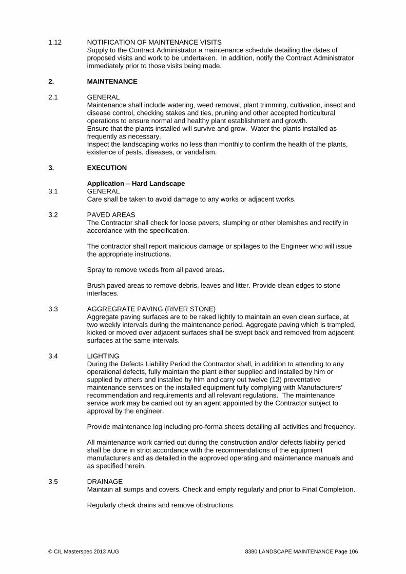
© CIL Masterspec 2013 AUG 8380 LANDSCAPE MAINTENANCE Page 106
1.12 NOTIFICATION OF MAINTENANCE VISITS Supply to the Contract Administrator a maintenance schedule detailing the dates of
proposed visits and work to be undertaken. In addition, notify the Contract Administrator immediately prior to those visits being made.
2. MAINTENANCE 2.1 GENERAL Maintenance shall include watering, weed removal, plant trimming, cultivation, insect and
disease control, checking stakes and ties, pruning and other accepted horticultural operations to ensure normal and healthy plant establishment and growth.
Ensure that the plants installed will survive and grow. Water the plants installed as frequently as necessary.
Inspect the landscaping works no less than monthly to confirm the health of the plants, existence of pests, diseases, or vandalism.
3. EXECUTION Application – Hard Landscape 3.1 GENERAL
Care shall be taken to avoid damage to any works or adjacent works.
3.2 PAVED AREAS The Contractor shall check for loose pavers, slumping or other blemishes and rectify in accordance with the specification. The contractor shall report malicious damage or spillages to the Engineer who will issue the appropriate instructions. Spray to remove weeds from all paved areas. Brush paved areas to remove debris, leaves and litter. Provide clean edges to stone interfaces.
3.3 AGGREGRATE PAVING (RIVER STONE) Aggregate paving surfaces are to be raked lightly to maintain an even clean surface, at two weekly intervals during the maintenance period. Aggregate paving which is trampled, kicked or moved over adjacent surfaces shall be swept back and removed from adjacent surfaces at the same intervals.
3.4 LIGHTING During the Defects Liability Period the Contractor shall, in addition to attending to any operational defects, fully maintain the plant either supplied and installed by him or supplied by others and installed by him and carry out twelve (12) preventative maintenance services on the installed equipment fully complying with Manufacturers’ recommendation and requirements and all relevant regulations. The maintenance service work may be carried out by an agent appointed by the Contractor subject to approval by the engineer. Provide maintenance log including pro-forma sheets detailing all activities and frequency. All maintenance work carried out during the construction and/or defects liability period shall be done in strict accordance with the recommendations of the equipment manufacturers and as detailed in the approved operating and maintenance manuals and as specified herein.
3.5 DRAINAGE Maintain all sumps and covers. Check and empty regularly and prior to Final Completion. Regularly check drains and remove obstructions.

© CIL Masterspec 2013 AUG 8380 LANDSCAPE MAINTENANCE Page 107
3.6 CARPENTRY
Maintain all timber surfaces, remove splinters, and drive home nails which sit proud. Furniture is to be kept clean of dirt or algae etcetera. Repair as required which may include re-sanding, rust treatment, painting and/or replacement of damaged parts.
3.7 OTHER HARD LANDSCAPE ITEMS Check that all items are free of defects and repair as specified. Application – Irrigation
3.8 GENERAL Maintain the Irrigation System in sound working order at all times to ensure water supply is kept up to all trees. Replace all parts including drippers found to be defective as specified. The Contractor shall regularly check timing switches and shut down the system over winter. All costs associated with frost damage resulting from failure to keep the system drained over the appropriate time period shall be met by the Contractor. It is important to ensure that the irrigation system is monitored, fully operational and set to achieve optimum plant growth especially in adversely dry conditions. Keep drains and kerb inlets clear and functional with respect to treepits and rain gardens. Application – Soft landscape
3.9 GENERAL Care shall be taken to avoid damage to any works or adjacent works. For planting the relevant planting rates shall be deemed to include all such costs and no additional payment shall be made for defects work under any circumstances.
3.10 GENERAL Maintenance shall include watering, weeding, trimming, cultivation, insect and disease control, checking of stakes and ties, pruning and other accepted horticultural operations to ensure normal and healthy plant establishment and growth. Also removal of litter and generally keeping the area neat and tidy. The relevant planting rates shall be deemed to include all such costs and no additional payment shall be made for defects work under any circumstances.
3.11 VANDALISED PLANTS Any plants vandalised after Practical Completion shall be notified in writing to the Engineer and shall be removed and replaced upon instruction. Those plants not notified to the Engineer shall be assumed to have died as a result of planting operations and shall be replaced at the Contractor's expense. The cost of plants or other landscape works deemed to have failed due to theft, willful damage or vandalism shall be the principal’s responsibility.
3.12 REPLACEMENTS PLANTS Replacements to make good defects must be planted during the planting season immediately following their loss. These shall be similar to those specified, previously supplied and approved unless otherwise agreed between the Engineer and the Contractor. All such replacement planting shall be at the Contractor's expense and the Contractor shall be responsible for any preparatory and other work necessary to enable planting to be properly carried out including the removal and disposal of dead materials.

© CIL Masterspec 2013 AUG 8380 LANDSCAPE MAINTENANCE Page 108
Replacement of plants which die through no fault of the Contractor may be required to be planted at the same time if so instructed by the Engineer. Any stakes, ties, etc shall be replaced as soon as possible after being found defective.
3.13 LITTER (INCLUDING LEAF FALL) The Contractor shall removal all litter material within the planted areas. Litter shall refer to all extraneous rubble which is detrimental to the appearance of the site. This rubbish is to include stones, bricks, debris, paper, confectionery and other wrappings, bottles, cans and plastic containers. It also includes organic material including dead animals. Litter is to be disposed of in an environmentally responsible manner. Allow for leaf fall removal at leaf fall season (generally 1 April – I July)
3.14 WATERING Where planter beds and trees are watered by an automatic irrigation system, operate and
manage the system to ensure that all beds receive adequate water at all times. Adjust the watering periods as necessary to accommodate seasonal fluctuations. Monitor Trees planted into paved areas for symptoms of water stress and provide
additional watering as necessary. Carefully monitor transplanted trees for symptoms of water stress and provide additional
watering as necessary. Additional to automatic irrigation, carry out watering by hand held hoses at regular
intervals as necessary during dry conditions to ensure successful plant establishment and growth.
Water shall be applied until the top 200mm of topsoil around each plant is saturated. Do not water during the hot part of the day. Watering nozzles shall be fine rose or
sprinkler heads to prevent damage to growth areas of the plants. 3.15 WEED CONTROL Remove and control weeds regularly throughout the period of maintenance. Keep weed free all cultivated planted areas to the extent that perennial weed species are
eradicated and annual weed species are well controlled. Take care not to disturb the shrub roots and excessive compaction of the bed surface. Additional weed control may be required in spring when the ground warms and seeds in the soil germinate.
Remove weeds by hand wherever possible. Spaying of weeds with an approved organic
herbicide with all necessary safety precautions may be required for persistent weeds; however the visible portion of the weed shall be removed as soon as the weed has died. Apply herbicide by spot spraying using a protective spray nozzle/cone. Selective weed sprays may be used in appropriate circumstances.
Inadequate mulch depth may allow excessive weed growth; therefore keep mulch topped up to the original specified depth
3.16 NOXIOUS PESTS AND DISEASES Monitor the works for insect and plant disease problems. If present, identify the problem
and apply appropriate remedy by accepted horticultural practices including chemical or biological methods.
Take all suitable precautions for the safe handling and application of herbicides, fungicides and insecticides and use these strictly in accordance with the manufacturer's specifications. In all cases, apply sprays on windless days. If the site is in a public area, the public shall be advised by signage that spraying is occurring and shall be directed away from the spray area.
Avoid damage to neighbouring properties caused by spraying. Should animal pests be encountered, reefer to guidance in Source Department of Conservation Document Standard operating procedures for managing animal pests
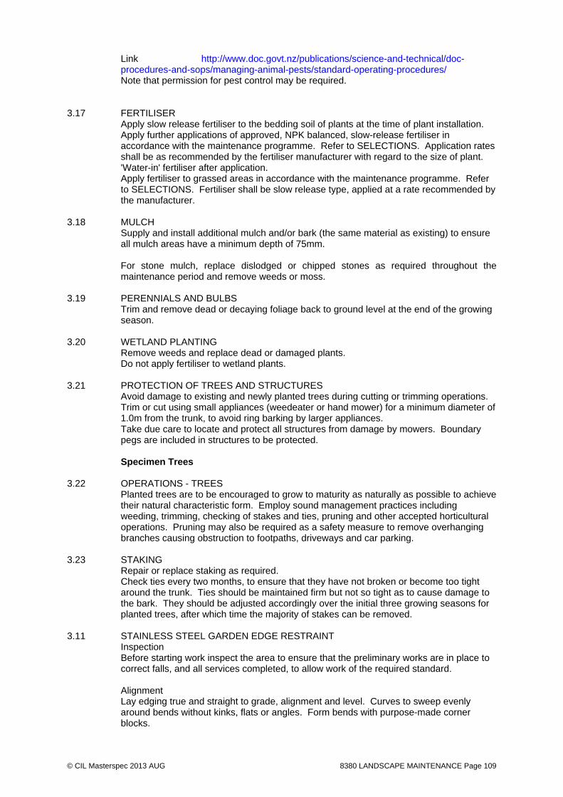
© CIL Masterspec 2013 AUG 8380 LANDSCAPE MAINTENANCE Page 109
Link http://www.doc.govt.nz/publications/science-and-technical/doc-procedures-and-sops/managing-animal-pests/standard-operating-procedures/ Note that permission for pest control may be required.
3.17 FERTILISER Apply slow release fertiliser to the bedding soil of plants at the time of plant installation. Apply further applications of approved, NPK balanced, slow-release fertiliser in
accordance with the maintenance programme. Refer to SELECTIONS. Application rates shall be as recommended by the fertiliser manufacturer with regard to the size of plant.
'Water-in' fertiliser after application. Apply fertiliser to grassed areas in accordance with the maintenance programme. Refer
to SELECTIONS. Fertiliser shall be slow release type, applied at a rate recommended by the manufacturer.
3.18 MULCH Supply and install additional mulch and/or bark (the same material as existing) to ensure
all mulch areas have a minimum depth of 75mm.
For stone mulch, replace dislodged or chipped stones as required throughout the maintenance period and remove weeds or moss.
3.19 PERENNIALS AND BULBS Trim and remove dead or decaying foliage back to ground level at the end of the growing
season. 3.20 WETLAND PLANTING Remove weeds and replace dead or damaged plants. Do not apply fertiliser to wetland plants. 3.21 PROTECTION OF TREES AND STRUCTURES Avoid damage to existing and newly planted trees during cutting or trimming operations.
Trim or cut using small appliances (weedeater or hand mower) for a minimum diameter of 1.0m from the trunk, to avoid ring barking by larger appliances.
Take due care to locate and protect all structures from damage by mowers. Boundary pegs are included in structures to be protected.
Specimen Trees 3.22 OPERATIONS - TREES Planted trees are to be encouraged to grow to maturity as naturally as possible to achieve
their natural characteristic form. Employ sound management practices including weeding, trimming, checking of stakes and ties, pruning and other accepted horticultural operations. Pruning may also be required as a safety measure to remove overhanging branches causing obstruction to footpaths, driveways and car parking.
3.23 STAKING Repair or replace staking as required. Check ties every two months, to ensure that they have not broken or become too tight
around the trunk. Ties should be maintained firm but not so tight as to cause damage to the bark. They should be adjusted accordingly over the initial three growing seasons for planted trees, after which time the majority of stakes can be removed.
3.11 STAINLESS STEEL GARDEN EDGE RESTRAINT Inspection Before starting work inspect the area to ensure that the preliminary works are in place to
correct falls, and all services completed, to allow work of the required standard. Alignment Lay edging true and straight to grade, alignment and level. Curves to sweep evenly
around bends without kinks, flats or angles. Form bends with purpose-made corner blocks.

© CIL Masterspec 2013 AUG 8380 LANDSCAPE MAINTENANCE Page 110
Tolerances Maximum deviation from alignment. Vertical: 5mm in 2.0m Horizontal: 5mm in 2.0m Installation Excavate for and set edging in place to line and levels shown. The operation shall be
carefully controlled to ensure that the precast edging is not displaced or damaged.
3.24 PRUNING Pruning during maintenance period.
At the end of the first growing season, all of the trees and shrubs shall be checked for any dead wood, broken or damaged branches which shall be cut out. Prune as required to ensure there is no obstruction of lighting ,signage or walkways.
3.25 CROWN LIFTING Allow to crown lift all trees to 1500mm clear height or as directed by the Engineer.
3.26 WATERING / IRRIGATION Ensure the automatic system is operational at all times, check for leaks and blockages and take corrective action as required. THE AUTOMATIC IRRIGATION IS FOR THE TREE PLANTING, BANKS WITH SOIL RETAINMENT AND LAWNS ONLY. MANUAL WATERING OF ALL OTHER PLANTING IS REQUIRED. Generally, ensure all planting is watered at night between 9pm to 6am a minimum of once every 7 days with each plant receiving a minimum of 25 litres. During periods of extended rainfall suspend the watering programme. During periods of extended heat increase the frequency of watering.
Completion 3.27 REPLACE Replace damaged, cracked or marked elements. 3.28 LEAVE Leave work to the standard required by following procedures. 3.29 REMOVE Remove debris, unused materials and components from the site. 3.30 PRUNING Undertake regular light pruning of specimen trees over a period of time to avoid one
severe pruning. Excessive foliage removal should be avoided which may result in wind damage or sun scalding and loss of the tree's aesthetic appearance. Remove broken or dangerously overhanging branches.
Prune back overhanging branches to a minimum clearance of 2.3m above the ground. Remove dead and broken branches. Care must be taken when removing branches to prevent further damage to the tree.
Prune back to a sound healthy branch with a clean cut, in accordance with good arboricultural practice. Final cuts shall be made as close as possible to the branch collar without damaging the collar, and apply wound treatment where necessary.
Dispose of all pruning waste off site. 3.31 FORKING Regularly fork tree pits within paved areas to loosen the ground in order to avoid
compaction, which can reduce the infiltration of water into the ground. Shrubs and Ground Cover

© CIL Masterspec 2013 AUG 8380 LANDSCAPE MAINTENANCE Page 111
3.32 OPERATIONS - SHRUBS AND GROUND COVER Maintain planting beds to establish good plantings, and achieve a high level of lush
vegetation with visual impact. Maintenance shall include weed control, trimming, watering and fertilising. Ground cover plants should grow to fully cover the ground and thus reduce weed growth and maintenance.
Maintain planting beds to a neat and tidy appearance to at least the same condition as at Practical Completion.
3.33 TRIMMING Undertake regular trimming of shrubs to maintain the following aspects: - Removal of dead heads after flowering - Removal of dead or old weak growth - Cutting back to encourage growth vigour - Thinning out mass planted areas to allow stronger plants to dominate 3.34 CLIMBERS Train climbing shrubs to grow over the climbing frame and wires. Adjust vegetation and
tie to wires to encourage even spread over the structure where necessary. 3.35 HEDGES Trim hedge shrubs to form low hedges to the height, shape and form shown on the
drawings. Grass 3.36 GRASSED AREAS Protect and maintain grassed areas to produce an even sward of grass at a uniform
height and healthy colour by watering, mowing and spraying. Maintain turf to a good quality with a neat appearance.
Protect newly sown and grassed areas against traffic until the grass is well established. If necessary top dress the turf with clean screened soil to eliminate minor hollows.
Applications shall be less than 15mm at any one time, preferably applied in spring or autumn.
Protect and maintain all grassed areas by watering, mowing and spraying to maintain a good quality turf with a neat appearance.
3.37 TEMOPARY PROTECTION Newly sown areas and turfed areas are to be protected against traffic until the grass is well established. Remove temporary protective fences at the end of the planting establishment period.
3.38 WEAR AND TEAR
The Contractor shall notify the Engineer of areas which in his opinion have become worn due to wear and tear. Appropriate action shall then be advised.
3.39 TOPDRESSING If necessary the lawn shall be topdressed with clean screened soil to eliminate minor hollows. Do not apply more than 15mm at any one time, preferably in spring or autumn.
3.40 MOWING ./ GRASS CUTTING Undertake grass cutting in dry conditions using a suitable mower with sharp blades. The
first cut shall be after the grass has reached a height of 100mm. Cut off one third of the height of the grass.
Cutting thereafter shall be undertaken in accordance with the maintenance schedule.
Refer to SELECTIONS. Before each cut, remove all litter, stones and other debris so that a tidy appearance is
maintained at all times. Neatly trim edges to paths and around trees or structures each time the grass is mowed.
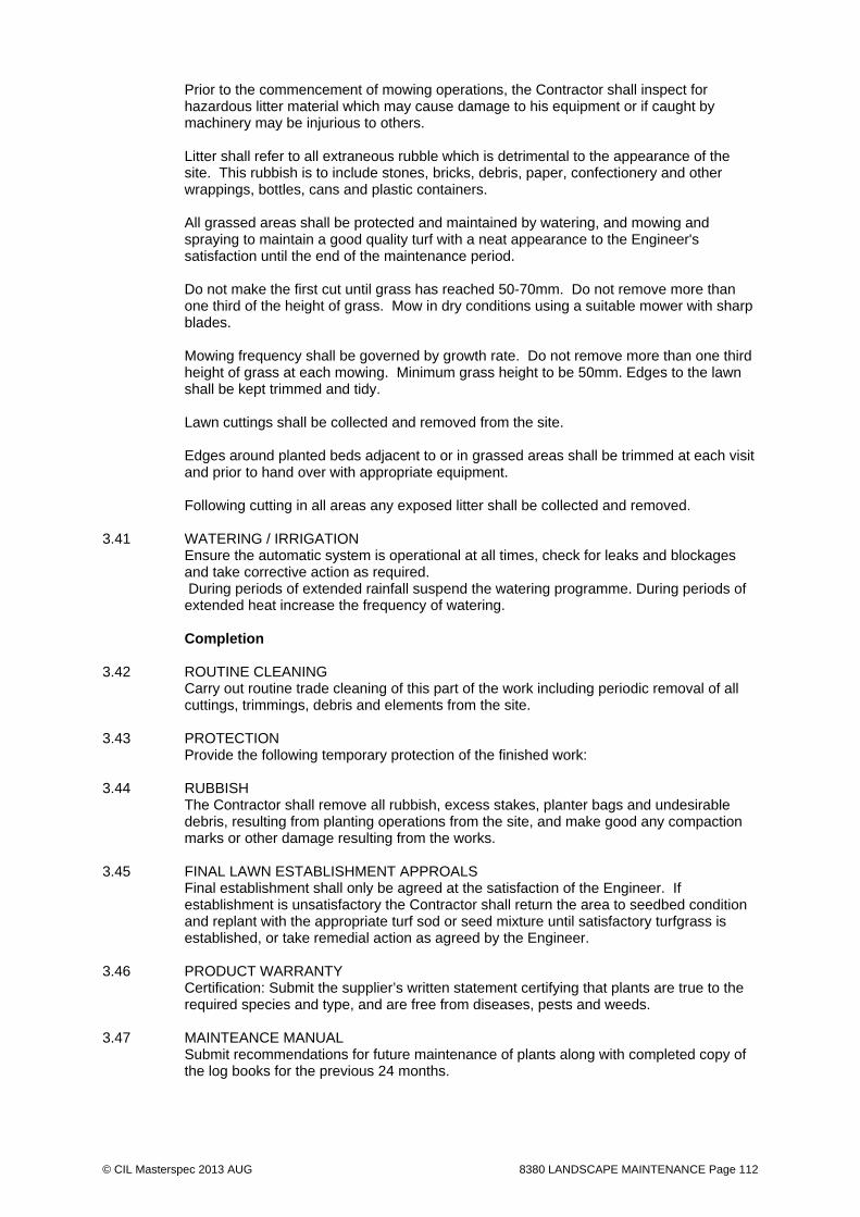
© CIL Masterspec 2013 AUG 8380 LANDSCAPE MAINTENANCE Page 112
Prior to the commencement of mowing operations, the Contractor shall inspect for hazardous litter material which may cause damage to his equipment or if caught by machinery may be injurious to others. Litter shall refer to all extraneous rubble which is detrimental to the appearance of the site. This rubbish is to include stones, bricks, debris, paper, confectionery and other wrappings, bottles, cans and plastic containers. All grassed areas shall be protected and maintained by watering, and mowing and spraying to maintain a good quality turf with a neat appearance to the Engineer's satisfaction until the end of the maintenance period. Do not make the first cut until grass has reached 50-70mm. Do not remove more than one third of the height of grass. Mow in dry conditions using a suitable mower with sharp blades. Mowing frequency shall be governed by growth rate. Do not remove more than one third height of grass at each mowing. Minimum grass height to be 50mm. Edges to the lawn shall be kept trimmed and tidy. Lawn cuttings shall be collected and removed from the site. Edges around planted beds adjacent to or in grassed areas shall be trimmed at each visit and prior to hand over with appropriate equipment. Following cutting in all areas any exposed litter shall be collected and removed.
3.41 WATERING / IRRIGATION Ensure the automatic system is operational at all times, check for leaks and blockages and take corrective action as required. During periods of extended rainfall suspend the watering programme. During periods of extended heat increase the frequency of watering.
Completion 3.42 ROUTINE CLEANING Carry out routine trade cleaning of this part of the work including periodic removal of all
cuttings, trimmings, debris and elements from the site. 3.43 PROTECTION Provide the following temporary protection of the finished work: 3.44 RUBBISH
The Contractor shall remove all rubbish, excess stakes, planter bags and undesirable debris, resulting from planting operations from the site, and make good any compaction marks or other damage resulting from the works.
3.45 FINAL LAWN ESTABLISHMENT APPROALS Final establishment shall only be agreed at the satisfaction of the Engineer. If establishment is unsatisfactory the Contractor shall return the area to seedbed condition and replant with the appropriate turf sod or seed mixture until satisfactory turfgrass is established, or take remedial action as agreed by the Engineer.
3.46 PRODUCT WARRANTY
Certification: Submit the supplier’s written statement certifying that plants are true to the required species and type, and are free from diseases, pests and weeds.
3.47 MAINTEANCE MANUAL Submit recommendations for future maintenance of plants along with completed copy of the log books for the previous 24 months.

© CIL Masterspec 2013 AUG 8380 LANDSCAPE MAINTENANCE Page 113
3.48 COMPLETION Product warranty At Practical Completion, submit supplier’s written statements certifying that plants are true to the required species and type, and are free from diseases, pests and weeds. At the end of the Establishment Period, submit a Guide Maintenance manual outlining recommended operations and treatments for the maintenance of the landscape works.
4. SELECTIONS 4.1 MAINTENANCE SCHEDULE - TREES, SHRUBS, GROUND COVER To be completed by Contract for Landscape Architects approval. Staking Trimming Hedge
trimming Fertilizer Weed
control Watering Replace
ment Mulch top up
Jan
Feb
Mar
Apr
May
Jun
Jul
Aug
Sep
Oct
Nov
Dec

© CIL Masterspec 2013 AUG 8380 LANDSCAPE MAINTENANCE Page 114
4.2 MAINTENANCE SCHEDULE – GRASS To be completed by Contract for Landscape Architects approval. Mowing
(medium) Mowing (rough)
Edge trimming
Fertilizer Weed control
Watering Over-sowing
Jan
Feb
Mar
Apr
May
Jun
Jul
Aug
Sep
Oct
Nov
Dec
4.3 MAINTENANCE SCHEDULE - RAINGARDEN To be completed by Contract for Landscape Architects approval. Staking Anchorage Fertilizer Weed
control Replacement
Jan
Feb
Mar
Apr
May
Jun
Jul
Aug
Sep
Oct
Nov
Dec
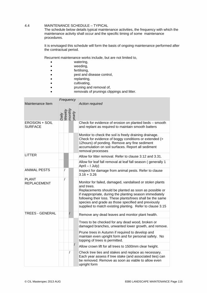
© CIL Masterspec 2013 AUG 8380 LANDSCAPE MAINTENANCE Page 115
4.4 MAINTENANCE SCHEDULE – TYPICAL The schedule below details typical maintenance activities, the frequency with which the
maintenance activity shall occur and the specific timing of some maintenance procedures.
It is envisaged this schedule will form the basis of ongoing maintenance performed after
the contractual period.
Recurrent maintenance works include, but are not limited to, watering, weeding, fertilising, pest and disease control, replanting, cultivating, pruning and removal of, removals of prunings clippings and litter.
Maintenance Item
Frequency Action required
Dai
ly
Wee
kly
mon
thly
ye
arly
EROSION + SOIL SURFACE
Check for evidence of erosion on planted beds – smooth and replant as required to maintain smooth batters
Monitor to check the soil is freely draining drainage. Check for evidence of boggy conditions or extended (> 12hours) of ponding. Remove any fine sediment accumulation on soil surfaces. Report all sediment removal processes
LITTER Allow for litter removal. Refer to clause 3.12 and 3.31.
Allow for leaf fall removal at leaf fall season ( generally 1 April – I July)
ANIMAL PESTS / Inspect for damage from animal pests. Refer to clause 3.16 + 3.26
PLANT REPLACEMENT
/ Monitor for failed, damaged, vandalised or stolen plants and trees. Replacements should be planted as soon as possible or if inappropriate, during the planting season immediately following their loss. These plants/trees shall be the same species and grade as those specified and previously supplied to match existing planting. Refer to clause 3.15
TREES - GENERAL / Remove any dead leaves and monitor plant health.
Trees to be checked for any dead wood, broken or damaged branches, unwanted lower growth, and remove.
Prune trees in Autumn if required to develop and maintain even upright form and for personal safety. No topping of trees is permitted.
/ Allow crown lift for all trees to 1500mm clear height.
/ Check tree ties and stakes and replace as necessary. Each year assess if tree stake (and associated ties) can be removed. Remove as soon as viable to allow even upright form

© CIL Masterspec 2013 AUG 8380 LANDSCAPE MAINTENANCE Page 116
Check for insect attack or disease and provide proposal for eradication for approval.
PLANTS - GENERAL
/ Remove any dead leaves and monitor plant health. Shrubs to be checked for any dead wood, broken or
damaged branches, unwanted lower growth, and remove. Replant dead plants or bare patches larger than 10% of
garden bed surface Check for insect attack or disease and provide proposal
for eradication for approval. Maintenance Item
Frequency Action required
Dai
ly
wee
kly
Mon
thly
Yea
rly
LAWN AREAS Allow to mow lawn to specification (clause 3.31) Check for lawn wear and tear. Refer to clause 3.29 Allow for topdressing if required (bi yearly) Check for insect attack or disease and provide proposal
for eradication for approval.
WEEDING, CULTIVATION
/
Ongoing hand weeding is required to maintain weed free tree pits, garden beds and terraces.
MULCHING / Top up mulch as necessary to maintain original specified depth and lines and keep weed-free throughout. Rake to ensure an even loose surface around plants and across the area generally ensuring no mixing of soil/weeds at all times. Pull mulch away from stems of plants and trees if piled up around stems.
FERTILISING / Fertilise in late spring or as per manufacturers recommendation of fertiliser as per Specification clause 3.20 and 3.28 above (this section)
WATERING – IRRIGATION SYSTEM (NOTE: the automatic irrigation is for the tree planting, banks with soil reinforcement + lawns only. Manual watering of other is required.
Maintain the Irrigation System in sound working order at all times to ensure water supply is kept up to all trees. Replace all parts including drippers found to be defective as specified. (refer to clause 3.08)
Check timing switches Shut down the system over winter.
WATERING – MANUAL
Water during maintenance period to allow for plant establishment. Generally ensure planting is watered a minimum of once a week and more during times of drought and less during excessive rainfall. Refer to clause 3.23 + 3.32 above.
SUMMER Monitor all planting to ensure there is not drought stress and immediately resolve with manually irrigate those plants that require additional watering. In times of drought, manually irrigation all planting every 2 days. Regular deep watering is recommended.

© CIL Masterspec 2013 AUG 8380 LANDSCAPE MAINTENANCE Page 117
Maintenance Item
Frequency Action required
Dai
ly
wee
kly
Mon
thly
Yea
rly
HYDRAULIC STRUCTURES
/ Check that all structures (: inlet pipes, weirs, culverts and particularly outlet pipes; overflow pits) are free of debris and are not blocked. Remove debris if more than 20% blocked
END OF SECTION

© CIL Masterspec 2013 DEC 8422 CARPENTRY Page 118
8422 CARPENTRY 1. GENERAL This section relates to the supply and erection of exterior
light timber framing timber decking. Timber screen (to creche) and gate (with SS frame) Timber to seats Timber to bollard B1
1.1 RELATED WORK
Refer to 4924 LANDSCAPE METALWORK for metalwork Refer to 6711R RESENE PAINTING EXTERIOR for painting finishes Refer to 8461 STREET FURNITURE for furniture
1.2 DOCUMENTS Refer to the general section 1233 REFERENCED DOCUMENTS. The following
documents are specifically referred to in this section: NZBC B2/AS1 Durability NZBC D1/AS1 Access routes NZBC E2/AS1 External Moisture AS/NZS 1328.1 Glued laminated structural timber - Performance requirements and
minimum production requirements AS/NZS 1748.1 Timber - Solid - Stress graded for structural purposes - General
requirements AS/NZS 2269.0 Plywood - Structural - Specification AS/NZS 2904 Damp-proof courses and flashings NZS 3602 Timber and wood-based products for use in building NZS 3603 Timber structures standard NZS 3604 Timber-framed buildings NZS 3622 Verification of timber properties NZS 3640 Chemical preservation of round and sawn timber NZS 4121 Design for access and mobility - Buildings and associated facilities AS/NZS 4347.0 Damp-proof courses and flashings - Methods of test - General
introduction, list of methods and test specimen requirements 1.3 MANUFACTURER'S DOCUMENTS Manufacturer's and supplier's documents relating to work in this section are:
Suppliers specifications FSC certification (or similar approved)
1.4 DEFINITIONS
For the purposes of this section the definitions given below apply, Moisture content: The percentage by mass of water present in the timber. Equilibrium moisture content (EMC): For given conditions of humidity and temperature, the moisture content which timber approaches at which it neither gains nor loses moisture while the conditions of its environment are maintained. Feature: Any figure, grain, natural variation or similar which affects timber appearance. Butt joints: Boards cross cut square with plain ends for joining over supports.
Performance

© CIL Masterspec 2013 DEC 8422 CARPENTRY Page 119
1.5 SLIP RESISTANCE FOR ACCESS ROUTES Slip resistance for decking to comply with NZBC D1/AS1: 2.0 Level access routes and 3.0
Ramps; NZS 3604, 7.4.4 Surface. - when in place on a level access route, to have a mean coefficient of friction (µ) not less
than 0.4 when tested in accordance with AS/NZS 3661.1. - when in place on a sloping access route, to have a coefficient of friction (µ) not less
than 0.4 + 0.0125S (S = slope of surface expressed as a percentage). 1.6 PROVIDE EVIDENCE OF SLIP RESISTANCE Provide evidence that the decking complies with the standard of performance specified. 1.7 CERTIFY SLIP RESISTANCE Provide certificates and any other evidence at the time of selection/supply that the
decking complies with NZBC D1/VM1, NZBC D1/AS1: Access route and NZS 3604, 7.4.4 Surface.
1.8 SHOP DRAWINGS
Refer to requirements as part of other sections, including: All seats 8461 Street furniture
1.9 SAMPLES Submit representative samples of each material, packed to prevent contamination and labelled to indicate source and content. Allow 2 weeks for review. Sample schedule
Item Sample required
TIMBER DECKS
Timber deck.bridge and stairs by Crèche
1 timber unit
SEATS
S1 Timber bench with steel frame No back
1 timber unit
S2 Timber bench with steel frame With back
1 timber unit
S3 Timber stool with steel frame No back
1 timber unit
S4 Modified S1 attached to wall
1 timber unit
SCREENS
Timber screen by crèche 2m section
PERGOLA
Various timbers – refer to ####3
1 timber unit
BOLLARD
Timber to B1 bollard 1 timber unit
1.10 VERIFICATION
Certification: Submit a supplier’s certificate (which may be included on an invoice or delivery docket) verifying conformance to grading and noting moisture content. Sourcing: Where hardwood is required use only certified plantation grown timbers and provide verification of this source

© CIL Masterspec 2013 DEC 8422 CARPENTRY Page 120
1.11 DIMENSIONS All timber sizes are actual minimum dried sizes.
Maximum deviation of the finished floor surface under a 3 m straight edge laid in any direction: 1 mm.
1.12 ACCESSIBLE ROUTES Where required by NZBC D1/AS1 and NZS 4121, Appendix A, accessible routes for
people with disabilities to comply with NZS 4121, section 6, Footpaths, Ramps and Landings.
PERFORMACE 1.13 INSPECTIONS
Give notice so that inspection may be made of the following: Hold points for timber decking
Installation of joist and bearers and all works required by Structural engineer.
Completion of works Timber edge Completion of works
1.14 TESTS
For Product moisture content Confirm that the moisture content of the timber conforms with the requirements of BRANZ Bulletin 343 and matches the moisture content of the substrate as measured on site. If there is a mismatch allow for acclimatisation. Test method for timber products: To AS/NZS 1080.1.
2. PRODUCTS 2.1 PILES AND FOUNDATIONS Refer to 2323 TIMBER PILE FOUNDATIONS for piles and foundations. 2.2 HARDWOOD TIMBERS
Species, grade and moisture content in service as set out in NZS 3602. Either mechanically stress graded to AS/NZS 1748, or visual grading to NZS 3631. Plantation-grown selected hardwood. Satisfactory documentation is required for approval to ensure the timber sourced from a sustainably managed plantation. The timber is to be heart timber. For B1 bollard, pavillion + timber decking Timbers: Totara Supplier To the approval of the LA Durability grade Class I Moisture content 18% maximum. For all other timbers Timbers: Purpleheart Supplier To the approval of the LA Durability grade Class I Moisture content 18% maximum. Note: On site weather (minimum of 3 weeks) required prior to final fixing. No
leaching on finishes or furniture will be acceptable. The timber is to be well seasoned prior to final dressing.
© CIL Masterspec 2013 DEC 8422 CARPENTRY Page 121
Finish Decks: Dressed sawn for all decks to meet slip resistance.
Finish Balustrades and Furniture: Dressed all 6 sides and with arises removed
Provide required weathering of timbers to ensure colour leaching on final finishes does not occur.
2.3 GLULAM-ECONO TIMBERS Species, grade and moisture content in service as set out in NZS 3602. Either mechanically stress graded to AS/NZS 1748, or visual grading to NZS 3631. Plantation-grown selected timbers. The timber is to be heart timber. For crèche fence + gate Timbers: H3 glulam econo Supplier To the approval of the LA Durability grade H3 Note: Paint finish
2.4 SOLID TIMBER COMPONENTS
Selection to NZS 3602.
2.5 CORROSION RISKS For exterior timber, timber in damp areas and timber subject to occasional wetting, use
only stainless steel (or equivalent) fixings and components, if the timber is treated with; Copper Azole (CuAz, Preservative code 58), Alkaline Copper Quaternary (ACQ, Preservative code 90), Micronise Copper Azole (code 88) or Micronised Copper Quaternary (code 89). Also isolate any steel fences and gates etc. from timber with these treatments.
Timber gate and fences 2.6 TIMBER GATES Timber clad gate (hit and miss type to match adjacent screen fence) on stainless steel
frame, same height to the adjacent fence or wall. Leave 50mm to 100mm clearance under gates, depending on surface finish of adjacent ground. Check operation of gates to ensure that they swing clear of the ground and other features. Hang gates from stainless steel hinges on the up-slope post (if any).
Place latches up to 200mm from the top of the gate to a maximum of 1500mm off the ground, able to be locked with a padlock and accessible from both sides of the gate, through an 'access' hole for tall gates.
Hardware 2.7 NAILS Type to NZS 3604, section 4: Durability, and of the size and number for each particular
types of joint as laid down in the nailing schedules of NZS 3604, sections 6-10. 2.8 BOLTS AND SCREWS Bolts and screws of engineering and/or coach type complete with washers, to the
requirements of NZS 3604, section 4: Durability, and of the number and form required for each particular junction to NZS 3604, sections 6-10.
2.9 NAIL PLATES Comply with the requirements of NZS 3604, section 4: Durability, and of the number and
form required for each particular junction to NZS 3604, sections 6-10. Plates to the plate manufacturer's design for the particular locations as shown on the drawings.

© CIL Masterspec 2013 DEC 8422 CARPENTRY Page 122
2.10 CONNECTORS Comply with the requirements of NZS 3604, section 4: Durability, and of the number and
form required for each particular junction to NZS 3604, sections 6-10. Connectors and structural brackets to the connector manufacturer's design for particular locations shown on drawings.
2.11 CORROSION RISKS For exterior timber, timber in damp areas and timber subject to occasional wetting, use
only stainless steel (or equivalent) fixings and connectors, when the timber is treated with; Copper Azole (CuAz, Preservative code 58), Alkaline Copper Quaternary (ACQ, Preservative code 90), Micronise Copper Azole (code 88) or Micronised Copper Quaternary (code 89).
2.12 POLYETHYLENE DPC Polyethylene film to AS/NZS 2904 and to the appropriate test methods set out inAS/NZS
4347.0. Thickness 500 microns minimum, manufactured for use as a damp-proof course. 2.13 BITUMINOUS IMPREGNATED DPC Heavy Kraft impregnated with high grade bitumen and coated with higher heat resistant
bitumen to AS/NZS 2904 and to the appropriate test methods set out in AS/NZS 4347.0. Do not use with LOSP treated timber.
2.14 CONCRETE For piles and footings, 17.5 MPa prescribed mix concrete to NZS 3104, section 3,
Provisions for prescribed mix concrete, and NZS 3604, section 6.4.5, Pile footings. 3. EXECUTION Conditions 3.1 DELIVERY, STORAGE AND HANDLING Take delivery of materials and goods and store on site and protect from damage. Protect finished surfaces, edges and corners from damage. Move/handle goods in accordance with manufacturer's requirements. Reject and replace goods that are damaged or will not provide the required finish 3.2 TIMBER DECKING GENERALLY Execution to include those methods, practices and processes contained in the current
syllabus for the National Certificate in Carpentry and the National Certificate in Joinery (cabinetry, exterior joinery, stairs).
Check site dimensions. Carry out machining within the practices recommended for the
particular timber, wood product or pre-finished wood product being used. Machine drill and cut holes and recesses and form joints to the componentry manufacturer's recommendations. Work to be accurate, square and true to line and face.
Application – timber decking 3.3 FABRICATE AND INSTALL TIMBER STEPS Fabricate and install steps and landings to comply with NZBC D1/AS1:4.0 Stairways, and
unless detailed otherwise to BRANZ BU 497. 3.4 LAYING TIMBER SPACED BOARDING - EXTERIOR DECKS Confirm whether the grooved side of the boards is face up or face down. Avoid
excessively short or long lengths. Drill for all fixings. Stagger end joints. Space narrow boards (<100mm) a minimum of 2mm apart in general conditions, or minimum 3mm to 4mm apart if wide boards (>100mm) or narrow boards that are likely to swell after fixing, or 5mm apart for wide boards that are likely to swell. Leave a 12mm minimum gap between the exterior wall and the adjacent decking board.
3.5 SCREW FIXING Pre-drill for all fixings, where the screws allow, use a proprietary deck pre-drilling and
countersinking tool.

© CIL Masterspec 2013 DEC 8422 CARPENTRY Page 123
Use decking screws and power drive into the deck surface to just slightly below the board surface (approx. 0.5mm). Take care to not overdrive the screw as this may result in the screw heads or the boards being damaged. Refer to SELECTIONS.
3.6 CORROSION RISKS For exterior timber, timber in damp areas and timber subject to occasional wetting, use
only stainless steel or silicon bronze, fixings and connectors, if decking or framing timber is treated with; Copper Azole (CuAz, Preservative code 58), Alkaline Copper Quaternary (ACQ, Preservative code 90), Micronise Copper Azole (code 88) or Micronised Copper Quaternary (code 89).
Installation – timber decking 3.7 EXECUTION GENERALLY To NZS 3603 and NZS 3604 except as varied in this specification. Execution to include
those methods, practices and processes contained in the unit standards for the National Certificate in Carpentry and the National Certificate in Joinery (exterior joinery, and stairs etc).
3.8 SEPARATION Separate all timber framing timbers, except H4 and H5, from concrete, masonry and brick
by; - a full length DPC overlapping timber by at least 6mm; or - a 12mm minimum free draining air space Separate H3.2 structural timber, with a DPC, from H4 or H5 ground contact timber, if the
junction is within 300mm of the ground. 3.9 SET-OUT Set out framing in accordance with the requirements of NZS 3604. 3.10 FRAMING DECKS OR FLOORS Framed and fastened to NZS 3604, section 7, Floors. 3.11 FRAMING Frame to required loading and bracing complete with trimmers and nogs, all fabricated
and fastened to NZS 3604. 3.12 FRAMING ABUTTING BUILDINGS Where decks, pergolas or other framing abuts or is fixed to buildings, comply with NZBC
E2/AS1. Section 7 Decks and Pergolas. 3.13 LAYING TIMBER SPACED BOARDING FOR EXTERIOR DECKS Refer to 4383 TIMBER DECKING for exterior timber board decks. Installation/application – timber fence and gate 3.14 STANDARDS AND TOLERANCES Refer to the general section CONSTRUCTION for general requirements. 3.15 SETTING OUT Boundaries to be defined by legal survey pegs. Do not install fences where pegs have not
been located. In this event, instruction from the Contract Administrator on fence location is required.
Where fences are installed on property boundaries, fence lines shall be installed parallel to and 25mm within the subject property boundary.
If using palings or similar, fix palings on the road face of fences and inside faces of
internal boundaries. 3.16 EXCAVATIONS Excavate to the dimensions detailed on the drawings.

© CIL Masterspec 2013 DEC 8422 CARPENTRY Page 124
3.17 POST EMBEDMENT Embed posts with a minimum of 100mm clearance between the base of the excavation
and bottom of the post. Place concrete under and around the post and compact by tamping or vibrating. Ensure
the posts are set vertical and temporarily prop for at least two days after placement of concrete.
3.18 CLOSE BOARDED TIMBER FENCING Construct parallel to the ground surface. Post spacing 2.4 metres max. centres. Set the greater dimension of rails vertically, and outside face flush with the outside face of
posts. Fix rails to posts with 2 x 100mm nails at each post connection, and parallel to ground.
Fix palings 50mm above the ground surface with 10mm gaps between palings. Trim tops of palings parallel to the ground surface. 3.19 TIMBER GATES Timber clad gate (hit and miss type to match adjacent screen fence) on stainless steel
frame, same height to the adjacent fence or wall. Leave 50mm to 100mm clearance under gates, depending on surface finish of adjacent ground. Check operation of gates to ensure that they swing clear of the ground and other features. Hang gates from stainless steel hinges on the up-slope post (if any).
Place latches up to 200mm from the top of the gate to a maximum of 1500mm off the ground, able to be locked with a padlock and accessible from both sides of the gate, through an 'access' hole for tall gates.
3.20 TOLERANCES Posts shall not deviate by more than 30mm from the vertical over the height of the post. 3.21 REINSTATE Ensure all surfaces affected by the works are reinstated to pre-construction condition
(e.g. topsoiled and grassed). Completion 3.22 ROUTINE CLEANING Carry out routine trade cleaning of this part of the work including periodic removal all
debris, unused and temporary materials and elements from the site. 3.23 DEFECTIVE OR DAMAGED WORK Repair damaged or marked elements. Replace damaged or marked elements where
repair is not possible or will not be acceptable. Adjust operation of equipment and moving parts not working correctly. Leave work to the standard required for following procedures.
4. SELECTIONS 4.1 PILES AND FOUNDATIONS Refer to 2323 TIMBER PILE FOUNDATIONS for timber piles and poles. 4.2 SUB-FLOOR FRAMING Member Species Grade Treatment Bearers Radiata pine SG6 H3.2 CCA Deck joists: Radiata pine SG6 H3.2 CCA Note: All CCA preservative code 01 or 02 4.3 EXTERIOR EXPOSED TIMBERS Member Species Grade Treatment Framing: Radiata pine SG6 H3.2 CCA Posts (ground contact): Radiata pine SG6 H5 CCA Posts (non-ground contact): Radiata pine SG6 H3.2 CCA Joists: Radiata pine SG6 H3.2 CCA Exterior stairs and steps: Radiata pine ~ H3.2 CCA

© CIL Masterspec 2013 DEC 8422 CARPENTRY Page 125
Balustrades and handrails Radiata pine ~ H3.2 CCA Pergola: Radiata pine ~ H3.2 CCA Note: All CCA preservative code 01 or 02 4.4 EXTERNAL CARPENTRY
FURNITURE B1 – BOLLARD Element 4# lengths per bollard Timber HWD timber, Class 1 Refer to PRODUCTS, clause 2.2 or similar approved. Finish Timber oil. Refer to 3711R RESENE PAINTING EXTERIOR Size To drawing MPM-11-90723 “Bollards” S1,S2, S3 + S4 – SEAT Element timber seat and seat back members fixe to a SS frame Timber HWD timber, Class 1 Refer to PRODUCTS, clause 2.2 or similar approved. Finish Timber oil. Refer to 3711R RESENE PAINTING EXTERIOR Size To drawing MPM-11-90720 “Seat details 1” MPM-11-90721 “Seat details 2”
PAVILION
FENCE/ SCREEN + GATE Crèche timber fence/ screen and gate Element Posts, railing and pailings Timber Glulam Econo Refer to PRODUCTS, clause 2.2 or similar approved. Finish Painted. Refer to 3711R RESENE PAINTING EXTERIOR Size To drawing MPM-11-90740 “Balustrade details 1”
DECKING TO CRECHE Timber decking/bridge and stairs to creche Element Timber decking on HDG joists and post system. Timber HWD timber, Class 1 Refer to PRODUCTS, clause 2.2 or similar approved. Finish Timber oil. Refer to 3711R RESENE PAINTING EXTERIOR Size To drawing MPM-11-90114 “Creche finishes plan”
END OF SECTION

© CIL Masterspec 2013 APR 8461 STREET FURNITURE Page 126
8461 STREET FURNITURE 1. GENERAL This section relates to the supply and installation of exterior fixtures including; - Benches - Seats - Litter bins - Drinking fountains - Bollards This section relates to both manufacturer supplied and Custom made furniture. Note: For wheel stops refer to 3130 Precast concrete Related work 1.1 RELATED SECTIONS Refer to the appropriate concrete section(s) for concrete to furniture bases. Refer to 2110 SALVAGE for Brick pavers + concrete wall
Refer to 3124 INSITU CONCRETE - FINISHES for insitu concrete Refer to 3120 PRECAST CONCRETE - FINISHES for precast concrete Refer to 4924 LANDSCAPE METALWORK for metalwork Refer to 6711R RESENE PAINTING EXTERIOR for painting finishes Refer to 8422 CARPENTRY for timbers
Documents 1.2 DOCUMENTS Refer to the general section 1233 REFERENCED DOCUMENTS. The following
documents are specifically referred to in this section: NZS 3104 Specification for concrete production NZS 3124 Specification for concrete construction for minor works 1.3 MANUFACTURER'S DOCUMENTS Manufacturer's and supplier's documents relating to work in this section are:
Manufacturers installation specification Requirements 1.4 NO SUBSTITUTIONS Substitutions are not permitted to any specified system, or associated components and
products. 1.5 QUALIFICATIONS Work to be carried out by tradesmen experienced, competent and familiar with the
materials and installation requirements specified. 1.6 SUPPLIERS
Statements: Submit statements from suppliers of all furniture, giving the following, where applicable;
Particulars of the supplier’s experience in the required type of work. Production capacity for material of the required type, sizes and
quantity. Lead times for delivery of the material to the site.
1.7 SHOP DRAWINGS
Provide 1 set of shop drawings for review before manufacture showing: plans, elevations and sections methods of fixing methods of joint forming methods of fabrication and site assembly.

© CIL Masterspec 2013 APR 8461 STREET FURNITURE Page 127
overall dimensions; materials, thicknesses and finishes of elements including benches; type of construction including mitre joints and junctions of members; hardware type and location; detail and dimensions of stainless steel fixing caps for threaded rod ends temporary bracing, if required; procedures for shop and site assembly and fixing; and
Allow 2 weeks for review. Shop drawing schedule
Item Comment
BOLLARDS
B1 Bollard – type 1
Provide shop drawing
B3 Bollard – type 2
Provide shop drawing
SEATS
S1 Timber bench with steel frame No back
Provide shop drawing
S2 Timber bench with steel frame With back
Provide shop drawing
S3 Timber stool with steel frame No back
Provide shop drawing
S4 Modified S1 attahced to wall
Provide shop drawing
1.8 PROPTOTYPES
To be made in accordance with these specifications. Each shall be submitted for approval as the prototype for the various furniture items to be installed. The prototype shall be correct in regard to all dimensions, materials, and finishes specified in the drawings and specification including any integrated lighting, to enable it to be accepted as the approved prototype for the seats to be installed. Each element of the seat prototype design shall be submitted to the landscape architect for review before approval may be granted by the Engineer. Only after full approval is given for the sample seat that is submitted, shall the contractor proceed to fabrication of the various seats to be installed. Failure to obtain such approval in advance may result in the seats that are installed or fabricated, to be rejected. Allow 2 weeks for review. Prototype schedule
Item Comment
BOLLARDS
B1 Bollard – type 1
Provide 1# prototype for approval
B3 Bollard – type 2
Provide 1# prototype for approval
SEATS
S1 Timber bench with steel frame No back
Provide 1# prototype for approval
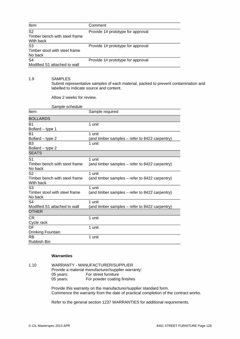
© CIL Masterspec 2013 APR 8461 STREET FURNITURE Page 128
Item Comment
S2 Timber bench with steel frame With back
Provide 1# prototype for approval
S3 Timber stool with steel frame No back
Provide 1# prototype for approval
S4 Modified S1 attached to wall
Provide 1# prototype for approval
1.9 SAMPLES
Submit representative samples of each material, packed to prevent contamination and labelled to indicate source and content. Allow 2 weeks for review. Sample schedule
Item Sample required
BOLLARDS
B1 Bollard – type 1
1 unit
B1 Bollard – type 2
1 unit (and timber samples – refer to 8422 carpentry)
B3 Bollard – type 2
1 unit
SEATS
S1 Timber bench with steel frame No back
1 unit (and timber samples – refer to 8422 carpentry)
S2 Timber bench with steel frame With back
1 unit (and timber samples – refer to 8422 carpentry)
S3 Timber stool with steel frame No back
1 unit (and timber samples – refer to 8422 carpentry)
S4 Modified S1 attached to wall
1 unit (and timber samples – refer to 8422 carpentry)
OTHER
CR Cycle rack
1 unit
DF Drinking Fountain
1 unit
RB Rubbish Bin
1 unit
Warranties 1.10 WARRANTY - MANUFACTURER/SUPPLIER Provide a material manufacturer/supplier warranty: 05 years: For street furniture 05 years: For powder coating finishes Provide this warranty on the manufacturer/supplier standard form. Commence the warranty from the date of practical completion of the contract works. Refer to the general section 1237 WARRANTIES for additional requirements.
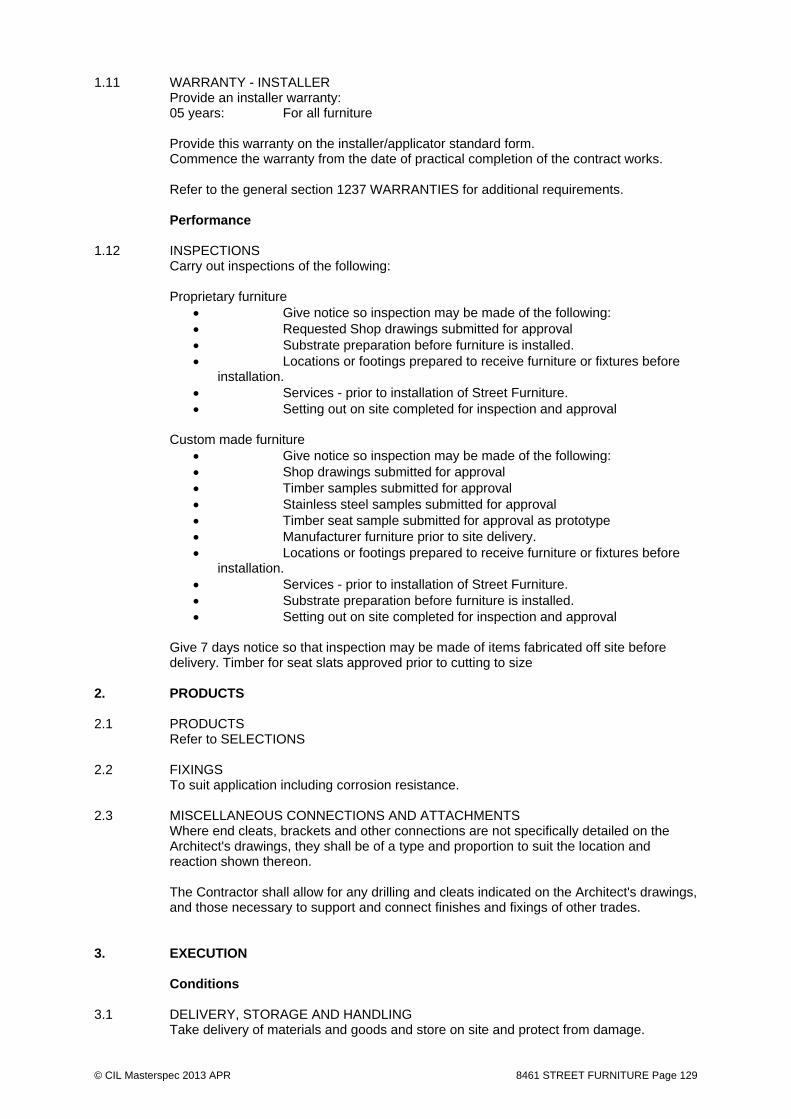
© CIL Masterspec 2013 APR 8461 STREET FURNITURE Page 129
1.11 WARRANTY - INSTALLER Provide an installer warranty: 05 years: For all furniture Provide this warranty on the installer/applicator standard form. Commence the warranty from the date of practical completion of the contract works. Refer to the general section 1237 WARRANTIES for additional requirements. Performance 1.12 INSPECTIONS Carry out inspections of the following:
Proprietary furniture
Give notice so inspection may be made of the following: Requested Shop drawings submitted for approval Substrate preparation before furniture is installed. Locations or footings prepared to receive furniture or fixtures before
installation. Services - prior to installation of Street Furniture. Setting out on site completed for inspection and approval
Custom made furniture
Give notice so inspection may be made of the following: Shop drawings submitted for approval Timber samples submitted for approval Stainless steel samples submitted for approval Timber seat sample submitted for approval as prototype Manufacturer furniture prior to site delivery. Locations or footings prepared to receive furniture or fixtures before
installation. Services - prior to installation of Street Furniture. Substrate preparation before furniture is installed. Setting out on site completed for inspection and approval
Give 7 days notice so that inspection may be made of items fabricated off site before delivery. Timber for seat slats approved prior to cutting to size
2. PRODUCTS 2.1 PRODUCTS Refer to SELECTIONS 2.2 FIXINGS To suit application including corrosion resistance. 2.3 MISCELLANEOUS CONNECTIONS AND ATTACHMENTS
Where end cleats, brackets and other connections are not specifically detailed on the Architect's drawings, they shall be of a type and proportion to suit the location and reaction shown thereon. The Contractor shall allow for any drilling and cleats indicated on the Architect's drawings, and those necessary to support and connect finishes and fixings of other trades.
3. EXECUTION Conditions 3.1 DELIVERY, STORAGE AND HANDLING Take delivery of materials and goods and store on site and protect from damage.

© CIL Masterspec 2013 APR 8461 STREET FURNITURE Page 130
Protect finished surfaces, edges and corners from damage. Move/handle goods in accordance with manufacturer's requirements. Reject and replace goods that are damaged or will not provide the required finish.
Implication Identification of a proprietary item or supplier for it does not necessarily imply exclusive preference for the item or supplier so identified but indicates the necessary properties of the item and a known source. Manufacturers or suppliers recommendations Transport, deliver, store, handle, protect, finish, adjust, prepare for use and install furniture items in accordance with the current written recommendations and instructions of the manufacturer or supplier. In the event of perceived conflicts with other requirements, submit the recommendations and instructions and advise of conflicts.
3.2 CUSTON FUNRITURE
Build the various furniture to match the approved Prototypes held by the Engineer and otherwise in accordance with the specification and shop drawings as approved. Accuracy: Build components square and install plumb. Joints: Provide materials in single lengths whenever possible. If joints are necessary make them over supports. Fixings To be as shown on drawings. All timbers fixings shall be countersunk as shown on the drawings. Allow to pre-drill hardwood timbers prior to driving fixings. All fixings shall be carefully aligned and driven just flush with surface of timber. Framing As indicated on the drawings, or as necessary to ensure that the construction is structurally sound. Finish of timbers All timber to of sound condition. All timber to be free of defects and splits for period up to end of defects liability period. Arises: Non required apart from all exposed edges to have 5mm radius
Installation 3.3 STREET FURNITURE Mount street furniture onto footings in accordance with manufacturer's recommendations. Erect all posts or poles vertically. Assemble items to manufacturer's requirements.
Erect/locate furniture items level. 3.4 SERVICES Allow for installation and connection of services. Completion 3.5 IN SITU TOUCH-UP In situ touch-up only after receiving written authority from the contract administrator. 3.6 ROUTINE CLEANING Carry out routine trade cleaning of this part of the work including periodic removal all
debris, unused and temporary materials and elements from the site.
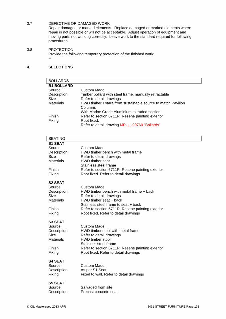
© CIL Masterspec 2013 APR 8461 STREET FURNITURE Page 131
3.7 DEFECTIVE OR DAMAGED WORK Repair damaged or marked elements. Replace damaged or marked elements where
repair is not possible or will not be acceptable. Adjust operation of equipment and moving parts not working correctly. Leave work to the standard required for following procedures.
3.8 PROTECTION Provide the following temporary protection of the finished work: ~ 4. SELECTIONS
BOLLARDS B1 BOLLARD Source Custom Made Description Timber bollard with steel frame, manually retractable Size Refer to detail drawings Materials HWD timber Totara from sustainable source to match Pavilion
Columns With Marine Grade Aluminium extruded section Finish Refer to section 6711R Resene painting exterior Fixing Root fixed. Refer to detail drawing MP-11-90760 “Bollards”
SEATING S1 SEAT
Source Custom Made Description HWD timber bench with metal frame Size Refer to detail drawings Materials HWD timber seat Stainless steel frame Finish Refer to section 6711R Resene painting exterior Fixing Root fixed. Refer to detail drawings
S2 SEAT Source Custom Made Description HWD timber bench with metal frame + back Size Refer to detail drawings Materials HWD timber seat + back Stainless steel frame to seat + back Finish Refer to section 6711R Resene painting exterior Fixing Root fixed. Refer to detail drawings
S3 SEAT Source Custom Made Description HWD timber stool with metal frame Size Refer to detail drawings Materials HWD timber stool Stainless steel frame Finish Refer to section 6711R Resene painting exterior Fixing Root fixed. Refer to detail drawings
S4 SEAT Source Custom Made Description As per S1 Seat Fixing Fixed to wall. Refer to detail drawings
S5 SEAT Source Salvaged from site Description Precast concrete seat
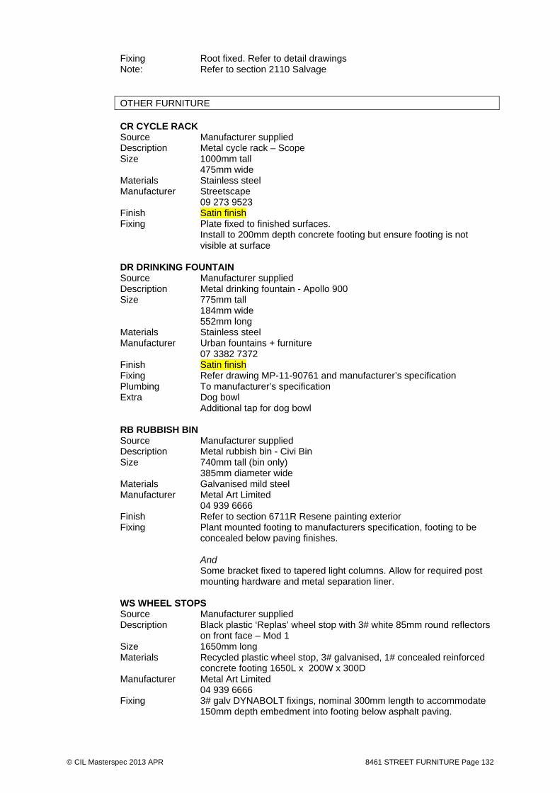
© CIL Masterspec 2013 APR 8461 STREET FURNITURE Page 132
Fixing Root fixed. Refer to detail drawings Note: Refer to section 2110 Salvage
OTHER FURNITURE
CR CYCLE RACK Source Manufacturer supplied Description Metal cycle rack – Scope Size 1000mm tall 475mm wide Materials Stainless steel Manufacturer Streetscape 09 273 9523 Finish Satin finish Fixing Plate fixed to finished surfaces. Install to 200mm depth concrete footing but ensure footing is not
visible at surface DR DRINKING FOUNTAIN
Source Manufacturer supplied Description Metal drinking fountain - Apollo 900 Size 775mm tall 184mm wide 552mm long Materials Stainless steel Manufacturer Urban fountains + furniture 07 3382 7372 Finish Satin finish Fixing Refer drawing MP-11-90761 and manufacturer’s specification Plumbing To manufacturer’s specification Extra Dog bowl Additional tap for dog bowl
RB RUBBISH BIN
Source Manufacturer supplied Description Metal rubbish bin - Civi Bin Size 740mm tall (bin only) 385mm diameter wide Materials Galvanised mild steel Manufacturer Metal Art Limited 04 939 6666 Finish Refer to section 6711R Resene painting exterior Fixing Plant mounted footing to manufacturers specification, footing to be
concealed below paving finishes. And Some bracket fixed to tapered light columns. Allow for required post
mounting hardware and metal separation liner.
WS WHEEL STOPS Source Manufacturer supplied Description Black plastic ‘Replas’ wheel stop with 3# white 85mm round reflectors
on front face – Mod 1 Size 1650mm long Materials Recycled plastic wheel stop, 3# galvanised, 1# concealed reinforced
concrete footing 1650L x 200W x 300D Manufacturer Metal Art Limited 04 939 6666 Fixing 3# galv DYNABOLT fixings, nominal 300mm length to accommodate
150mm depth embedment into footing below asphalt paving.

© CIL Masterspec 2013 APR 8461 STREET FURNITURE Page 133
CRECHE GRC PLANTERS Source Manufacturer supplied : Description GRC Lightweight planter trough and custom triangular planter Size 5No. 480d x 480w x 900length and
2No. 480d x 900w x 900length (triangle) Materials GRC - natural concrete colour Manufacturer Sanstone NZ 41 Jellicoe Rd, Panmure 1072
09-570 2112
SCULPTURE SF4 SCULPTURE
Source Tenth Trust supplied Description Cloak sculpture Size To be confirmed by Tenths Trust Materials To be confirmed by Tenths Trust Finish To be confirmed by Tenths Trust Fixing To be confirmed by Tenths Trust Note: Contractor is responsible for inspection at source, lifting/ craning at
source, delivery and installation.
TUNNEL POPPIES Source Custom Made Description Large circular stylised Poppies to be mechanically fixed to tunnel walls Size Refer drawing details Materials Marine grade aluminium Finish Powder coat red and black Fixing Refer drawings
END OF SECTION

© CIL Masterspec 2013 0000A SCHEDULES - DRAWING REGISTER Page 134
0000A SCHEDULES - DRAWING REGISTER

Document Transmittal Record for Issues from WALA 90
% i
ss
ue
10
0%
is
su
e
10
0%
WC
C i
ss
ue
1314 NWM PARK Day of Issue 09 20 10
Month 12 12 01
Year 13 13 14
100% Detailed Design MPA 1 1 1
MCH
WCC 1
Dwg Scale Drawing Title A1 A1 A1No. @A1 File Type PDF PDF PDF
ISSUE: FOR SIGN OFF
Drawings WALA LeaReview: Input/ Review By:
INTRODUCTION
100s - PLANS (Site Wide)
MP-11-90100 1:500 Site Reference plan WA AAL MPA AMP-11-90101 NTS Contents and Drawing Legends WA AAL MPA
MP-11-90110 1:200 Site Finshes - West 1 WA AAL MPA F G H
MP-11-90111 1:200 Site Finshes - Central 2 WA AAL MPA F G H
MP-11-90112 1:200 Site Finshes - East 3 WA AAL MPA D E F
MP-11-90113 1:200 Temp Site Finishes - West WA AAL MPA C D E
MP-11-90114 1:200 Creche Finishes WA AAL MPA D E F
MP-11-90120 1:200 Site Levels - West 1 WA AAL MPA F G H
MP-11-90121 1:200 Site Levels - Central 2 WA AAL MPA F G H
MP-11-90122 1:200 Site Levels - East 3 WA AAL MPA D E F
MP-11-90123 1:200 Temp Site Levels - West WA AAL MPA C D E
MP-11-90124 1:200 Creche Levels WA AAL MPA D E F
MP-11-90140 As Shown Furniture, Lighting & Signage - West 1 WA AAL MPA B C D
MP-11-90141 As Shown Furniture, Lighting & Signage - Centrral 2 WA AAL MPA B C D
MP-11-90142 As Shown Furniture, Lighting & Signage - East 3 WA AAL MPA B C D
MP-11-90150 As Shown Planting - West 1 WA AAL MPA B C D
MP-11-90151 As Shown Planting - Centrral 2 WA AAL MPA B C D
MP-11-90152 As Shown Planting - East 3 WA AAL MPA B C D
300s - PAVING & KERBING
MP-11-90300 1:200 Paving + Kerbing Reference Plan - West 1WA AAL MPA E F G
MP-11-90301 1:200 Paving + Kerbing Reference Plan - Centra WA AAL MPA E F G
MP-11-90302 1:200 Paving + Kerbing Reference Plan - East 3 WA AAL MPA D E F
MP-11-90310 As shown Detailed paving plan 1 WA AAL MPA A B
MP-11-90311 As shown Detailed paving plan 2 WA AAL MPA A B
MP-11-90312 As shown Detailed paving plan 3 WA AAL MPA A B
MP-11-90313 As shown Detailed paving plan 4 WA AAL MPA A B
MP-11-90314 As shown Detailed paving plan 5 WA AAL MPA A B
MP-11-90315 As shown Detailed paving plan 6 WA AAL MPA A B
MP-11-90320 1:200 Paving + Kerbing Interface Details 1 WA AAL MPA H I J
MP-11-90321 1:200 Paving + Kerbing Interface Details 2 WA AAL MPA G H I
MP-11-90322 1:200 Paving + Kerbing Interface Details 3 WA AAL MPA F G H
MP-11-90323 1:200 Paving + Kerbing Interface Details 4 WA AAL MPA E F G
MP-11-90324 1:200 Paving + Kerbing Interface Details 5 WA AAL MPA D E F
MP-11-90325 1:200 Paving + Kerbing Interface Details 6 WA AAL MPA C D E
MP-11-90326 1:200 Paving + Kerbing Interface Details 7 WA AAL MPA D E F
MP-11-90327 1:200 Paving + Kerbing Interface Details 8 WA AAL MPA B C D
MP-11-90328 1:200 Paving + Kerbing Interface Details 9 WA AAL MPA B C
MP-11-90340 As shown Typical Kerbing Details 1 WA AAL MPA H I J
MP-11-90341 As shown Typical Kerbing Details 2 WA AAL MPA G H I
MP-11-90342 As shown Typical Drainage Details 1 WA AAL MPA E F G
MP-11-90350 As shown Pedestrian Crossing 1 WA AAL MPA H I
MP-11-90360 As shown Creche Interface Details WA AAL MPA A B C
MP-11-90361 As shown Creche Interface Details WA AAL MPA A B B
MP-11-90362 As shown Creche Interface Details WA AAL MPA A

400s - WALLS, STAIRS AND RAMPS
MP-11-90400 1:200 Western Terraces Wall Reference Plan AAL WA MPA B C C
MP-11-90401 1:200 Central Area Wall Reference Plan AAL WA MPA B C C
MP-11-90402 1:200 Eastern Terraces Wall Reference Plan AAL WA MPA B C C
MP-11-90403 1:50 Western Terrace - Precast Walls 1-3 AAL WA MPA C D D
MP-11-90404 1:50 Western Terrace - Precast Walls 4-5 AAL WA MPA C D D
MP-11-90405 1:50 Western Terrace - Precast Walls 6-11 AAL WA MPA C D D
MP-11-90406 1:50 Central Area - Precast Walls 1-2 AAL WA MPA C D D
MP-11-90407 1:50 Central Area - Precast Walls 3-4 AAL WA MPA C D D
MP-11-90408 1:50 Central Area - Precast Wall 5 AAL WA MPA C D D
MP-11-90409 1:50 Central Area - Precast Walls 6-8 AAL WA MPA C D D
MP-11-90410 1:50 Tangata Whenua - Precast Wall 1 AAL WA MPA B C C
MP-11-90411 1:50 Tangata Whenua - Precast Walls 2-4 AAL WA MPA B C C
MP-11-90412 1:50 Eastern Terraces - Precast Walls 1-3 AAL WA MPA B C C
MP-11-90413 1:50 Eastern Terraces - Precast Walls 4-7 AAL WA MPA A B B
MP-11-90414 1:50 Eastern Terraces - Precast Walls 8-10 AAL WA MPA A B B
MP-11-90415 1:50 Eastern Terraces - Precast Wall 11 AAL WA MPA A B B
MP-11-90416 1:50 CrecheTerraces - Precast Walls 1-3 AAL WA MPA A B C
MP-11-90417 1:50 CrecheTerraces - Precast Walls 4 AAL WA MPA A B C
MP-11-90420 1:50 Precast Walls - Typical Details AAL WA MPA A B C
MP-11-90430 1:200 Stair Reference Plan - West 1 AAL/WA MPA E F G
MP-11-90431 1:200 Stair Reference Plan - Central 2 AAL/WA MPA C E F
MP-11-90432 1:200 Stair Reference Plan - East 3 AAL/WA MPA C D E
MP-11-90433 As Shown Stair Details 1 AAL/WA MPA C D E
MP-11-90434 As Shown Stair Details 2 AAL/WA MPA C D E
MP-11-90435 As Shown Stair Details 3 AAL/WA MPA C D E
MP-11-90436 As Shown Stair Details 4 AAL/WA MPA C D E
MP-11-90437 As Shown Stair Details 5 AAL/WA MPA C D E
MP-11-90438 As Shown Stair Details 6 AAL/WA MPA C D E
MP-11-90439 As Shown Stair Details 7 AAL/WA MPA C D E
MP-11-90440 As Shown Stair Details 8 AAL/WA MPA C D E
MP-11-90441 As Shown Stair Details 9 AAL/WA MPA B C D
MP-11-90442 As Shown Stair Details 10 AAL/WA MPA C D E
500s -TUNNEL AND CUTTING
MP-11-90500 1:500 Underpass Long Sections North & South AAL WA MPA B B
MP-11-90501 As Shown Underpass Northwest Walls Pre Cast seto AAL WA MPA B B
MP-11-90502 As Shown Underpass Northeast Walls Pre Cast setouAAL WA MPA B B
MP-11-90503 As Shown Underpass Southwest walls Pre Cast setouAAL WA MPA B B
MP-11-90504 As Shown Underpass Southeast walls Pre Cast setouAAL WA MPA B B
MP-11-90510 As Shown Underpass Wall Details 1 AAL WA MPA B B
MP-11-90511 As Shown Underpass Wall Details 2 AAL WA MPA B B
MP-11-90520 As Shown Tunnel Graphic Elevations AAL/WA MPA B B
MP-11-90521 As Shown Tunnel Graphic Details AAL/WA MPA B B
MP-11-90530 As Shown Tunnel Lid West Balustrade Plan AAL WA MPA A A
MP-11-90533 As Shown Tunnel Lid West Balustrade Details AAL WA MPA A A
MP-11-90535 As Shown Tunnel Lid East Balustrade AAL WA MPA B B
MP-11-90536 As Shown Tunnel Lid East Balustrade AAL WA MPA B B
MP-11-90537 As Shown Tunnel Lid East BalustradeDetails AAL WA MPA B B
MP-11-90538 As Shown Tunnel Lid East Balustrade Details AAL WA MPA B B
MP-11-90540 As Shown Typical Gap Balustrade AAL WA MPA B B

600s - SHELTERS
MP-11-90601 1:25 Pavilion 1 Taranaki St Plans AAL WA MPA C C
MP-11-90611 1:25 Pavilion 2 Buckle St Plans AAL WA MPA C C
Sections
MP-11-90620 1:50 Pavilion 1 Taranaki St - Sections AAL WA MPA A A
MP-11-90625 1:50 Pavilion 2 Buckle St - Sections AAL WA MPA A A
Details
MP-11-90650 As Shown Pavilion - Typical Details AAL WA MPA C C
700s - LIGHTING & FURNITURE
MP-11-90720 As Shown Seat details 1 WA AAL MPA B D E
MP-11-90721 As Shown Seat details 2 WA AAL MPA A C D
MP-11-90722 As Shown Seat details 3 WA AAL MPA A B
MP-11-90730 As Shown Handrail details 1 WA AAL MPA A A B
MP-11-90740 As Shown Balustrade/fence details 1 WA AAL MPA A A
MP-11-90750 As Shown Signage details 1 WA AAL MPA A B B
MP-11-90751 As Shown Signage details 2 WA AAL MPA A B B
MP-11-90760 As Shown Bollards details 1 WA AAL MPA A B
MP-11-90761 As Shown Misc details 1 WA AAL MPA A B
800s - PLANTING
MP-11-90800 1:200 Planting Reference Plan - West 1 WA AAL MPA E F G
MP-11-90801 1:200 Planting Reference Plan - Central 2 WA AAL MPA D E F
MP-11-90802 1:200 Planting Reference Plan - East 3 WA AAL MPA D E F
MP-11-90810 As Shown SH1 Pit Details 1 WA AAL MPA C D
MP-11-90811 As Shown SH1 Pit Details 2 WA AAL MPA D E F
MP-11-90812 As Shown SH1 Pit Details 3 WA AAL MPA C D E
MP-11-90813 As Shown SH1 Pit Details 4 WA AAL MPA C D
MP-11-90814 As Shown SH1 Pit Details 5 WA AAL MPA D E F
MP-11-90815 As Shown SH1 Pit Details 6 WA AAL MPA C D E
MP-11-90816 As Shown SH1 Pit Details 7 WA AAL MPA A B
MP-11-90817 As Shown SH1 Pit Details 8 WA AAL MPA A B
MP-11-90818 As Shown SH1 Pit Details 9 WA AAL MPA A B
MP-11-90819 As Shown SH1 Pit Details 10 WA AAL MPA A B
MP-11-90820 As Shown SH1 Pit Details 11 WA AAL MPA A B
MP-11-90821 As Shown SH1 Pit Details 12 WA AAL MPA A B
MP-11-90822 As Shown SH1 Pit Details 13 WA AAL MPA A B
MP-11-90823 As Shown SH1 Pit Details 14 WA AAL MPA A B
MP-11-90830 As Shown Typical Tree details 1 WA AAL MPA G H I
MP-11-90831 As Shown Typical Tree details 2 WA AAL MPA A B
MP-11-90832 As Shown Typical Tree details 3 WA AAL MPA A B
MP-11-90833 As Shown Typical Tree details 4 WA AAL MPA A B
MP-11-90840 As Shown Typical planting details 1 WA AAL MPA G H I

3D Model WALA LeaReview: Input/ Review By:
MP-11-3d Model Rhino model AAL/WA
Specification WALA LeaReview: Input/ Review By:
MP-11-Spec NTS Specification WA AAL MPA A B C
Schedules WALA LeaReview: Input/ Review By:
NTS Plant schedule WA AAL MPA B C DNTS Stone Masonry and Paving Schedule A WA AAL MPA
NTS Signage WA AAL MPA
NTS Lighting Schedule E3 AAL/WA MPA
NTS Furniture Schedule WA AAL MPA
Presentations WALA LeaReview: Input/ Review By:
CAD Files (DWG.) WALA LeaReview: Input/ Review By:
p_arch
p_finishes200
p_grid
p_land
p_landCONTOURS
p_legend
p_ref

© CIL Masterspec 2013 0000B SCHEDULES – PLANT SCHEDULE Page 136
0000B SCHEDULES – PLANT SCHEDULE

W+A
NWM Park Planting Schedule
Date: 15.11.13 Wraight Athfield Landscape & Architecture
Project: 1314 Memorial Park
Issue: A| 30% complete detailed design 15.11.13
B| 90% complete detailed design 09.12.13
C| 100% detailed design 20.12.13
D| 100% detailed design WCC 10.01.14
% Common NameSpacing
(m)Size Qty
Qty +
contingarea Comments
GB_01
SHRUB + GROUNDCOVER TOTAL AREA 31.9 m2
0% Ch.r Chionochloa rubra Red Tussock 0.6 PB3
0% He.o Hebe odora Hebe 0.6 PB3
0% Kn.PP Kniphofia 'Percys pride' Torch lily 0.6 PB3
0% TOTAL 0 0 no.
RG_01
TOTAL AREA 340.9 m2
10% As.g Astelia grandis Swamp Astelia 0.6 PB3 95 105
10% Bl.m Blechnum minus Swamp kio kio 0.6 PB3 95 105
10% Ca.d Carex dissita Purei 0.4 PB3 213 234
20% Ca.t Carex trifida Muttonbird sedge 0.4 PB3 426 469
10% Ca.s Carex secta Purei 0.6 PB3 95 105
20% Ca.v Carex virgata Purei 0.4 PB3 426 469
30% Fu.p Fuchsia procumbens Creeping Fuchsia 0.6 PB3 284 312
10% Li.i Libertia ixioides Nz Iris 0.4 PB3 213 234
30% Mu,a Muehlenbeckia axialaris 0.6 PB3 284 312
150% TOTAL 2131 2345 no.
TP_01‐05
TREES
ME Metrosideros excelsa Pohutukawa as shown 1500L 5 6
BUCKLE ST ‐ WEST
GB_02
SHRUB + GROUNDCOVER TOTAL AREA 44.2 m2
10% Bl.nz Blechnum novae zealandia 0.6 PB3 12 13
30% Ch.r Chionochloa rubra Red Tussock 0.6 PB3 37 41
20% He.o Hebe odora Hebe 0.6 PB3 25 28
32% Li.i Libertia ixioides NZ Iris 0.4 PB3 88 97
10% Kn.PP Kniphofia 'Percys pride' Torch lily 0.6 PB3 12 13
60% Lo.a Lobelia angulata Panakenake 0.6 PB3 74 81
20% Ro.RFC Rosa 'Red FlowerCarpet' Red Rose 0.6 PB3 25 28
182% TOTAL 273 301 no.
TP_11‐14
TREES
OE Olea sp Olive as shown 120‐160L 4 4
GB_03
SHRUB + GROUNDCOVER TOTAL AREA 47.0 m2
10% Bl.nz Blechnum novae zealandia 0.6 PB3 13 14
30% Ch.r Chionochloa rubra Red Tussock 0.6 PB3 39 43
20% He.o Hebe odora Hebe 0.6 PB3 26 29
33% Li.i Libertia ixioides NZ Iris 0.4 PB3 97 107
10% Kn.PP Kniphofia 'Percys pride' Torch lily 0.6 PB3 13 14
60% Lo.a Lobelia angulata Panakenake 0.6 PB3 78 86
20% Ro.RFC Rosa 'Red FlowerCarpet' Red Rose 0.6 PB3 26 29
183% TOTAL 292 322 no.
TP_18‐21
TREES
OE Olea sp Olive as shown 120‐160L 4 4
GB_04
SHRUB + GROUNDCOVER TOTAL AREA 46.1 m2
10% Bl.nz Blechnum novae zealandia 0.6 PB3 13 14
30% Ch.r Chionochloa rubra Red Tussock 0.6 PB3 38 42
20% He.o Hebe odora Hebe 0.6 PB3 26 29
32% Li.i Libertia ixioides NZ Iris 0.4 PB3 92 101
10% Kn.PP Kniphofia 'Percys pride' Torch lily 0.6 PB3 13 14
60% Lo.a Lobelia angulata Panakenake 0.6 PB3 77 85
20% Ro.RFC Rosa 'Red FlowerCarpet' Red Rose 0.6 PB3 26 29
182% TOTAL 285 314 no.
WESTERN TERRACES
P:\1314 Memorial Park\08doc\MP-11-Plant Schedule.xls 1

W+A
NWM Park Planting Schedule
Date: 15.11.13 Wraight Athfield Landscape & Architecture
Project: 1314 Memorial Park
Issue: A| 30% complete detailed design 15.11.13
B| 90% complete detailed design 09.12.13
C| 100% detailed design 20.12.13
D| 100% detailed design WCC 10.01.14
% Common NameSpacing
(m)Size Qty
Qty +
contingarea Comments
TP_24‐27
TREES
OE Olea sp Olive as shown 120‐160L 4 4
GB_05
SHRUB + GROUNDCOVER TOTAL AREA 52.3 m2
10% Bl.nz Blechnum novae zealandia 0.6 PB3 15 17
30% Ch.r Chionochloa rubra Red Tussock 0.6 PB3 44 48
20% He.o Hebe odora Hebe 0.6 PB3 29 32
32% Li.i Libertia ixioides NZ Iris 0.4 PB3 105 116
10% Kn.PP Kniphofia 'Percys pride' Torch lily 0.6 PB3 15 17
60% Lo.a Lobelia angulata Panakenake 0.6 PB3 87 96
20% Ro.RFC Rosa 'Red FlowerCarpet' Red Rose 0.6 PB3 29 32
182% TOTAL 324 358 no.
TP_30‐33
TREES
OE Olea sp Olive as shown 120‐160L 4 4
GB_06
SHRUB + GROUNDCOVER TOTAL AREA 22.2 m2
10% Bl.nz Blechnum novae zealandia 0.6 PB3 6 7
30% Ch.r Chionochloa rubra Red Tussock 0.6 PB3 19 21
20% He.o Hebe odora Hebe 0.6 PB3 12 13
32% Li.i Libertia ixioides NZ Iris 0.4 PB3 44 48
10% Kn.PP Kniphofia 'Percys pride' Torch lily 0.6 PB3 6 7
60% Lo.a Lobelia angulata Panakenake 0.6 PB3 37 41
20% Ro.RFC Rosa 'Red FlowerCarpet' Red Rose 0.6 PB3 12 13
182% TOTAL 136 150 no.
TP_37‐39
TREES
OE Olea sp Olive as shown 120‐160L 3 3
RG_02
TOTAL AREA 16.2 m2
10% As.g Astelia grandis Swamp Astelia 0.6 PB3 5 6
10% Bl.m Blechnum minus Swamp kio kio 0.6 PB3 5 6
10% Ca.d Carex dissita Purei 0.4 PB3 10 11
20% Ca.t Carex trifida Muttonbird sedge 0.4 PB3 20 22
10% Ca.s Carex secta Purei 0.6 PB3 5 6
20% Ca.v Carex virgata Purei 0.4 PB3 20 22
30% Fu.p Fuchsia procumbens Creeping Fuchsia 0.6 PB3 14 15
10% Li.i Libertia ixioides Nz Iris 0.4 PB3 10 11
30% Mu,a Muehlenbeckia axialaris 0.6 PB3 14 15
150% TOTAL 103 114 no.
TP_06
TREES
ME Metrosideros excelsa Pohutukawa as shown 1500L 1 1
RG_03
TOTAL AREA 28.0 m2
10% As.g Astelia grandis Swamp Astelia 0.6 PB3 8 9
10% Bl.m Blechnum minus Swamp kio kio 0.6 PB3 8 9
10% Ca.d Carex dissita Purei 0.4 PB3 18 20
20% Ca.t Carex trifida Muttonbird sedge 0.4 PB3 35 39
10% Ca.s Carex secta Purei 0.6 PB3 8 9
20% Ca.v Carex virgata Purei 0.4 PB3 35 39
30% Fu.p Fuchsia procumbens Creeping Fuchsia 0.6 PB3 23 25
10% Li.i Libertia ixioides Nz Iris 0.4 PB3 18 20
30% Mu,a Muehlenbeckia axialaris 0.6 PB3 23 25
150% TOTAL 176 195 no.
TP_07
TREES
ME Metrosideros excelsa Pohutukawa as shown 1500L 1 1
P:\1314 Memorial Park\08doc\MP-11-Plant Schedule.xls 2
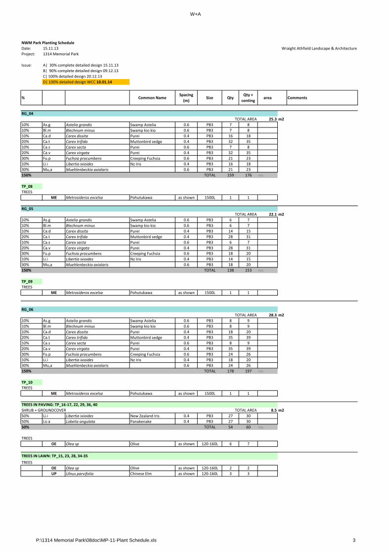
W+A
NWM Park Planting Schedule
Date: 15.11.13 Wraight Athfield Landscape & Architecture
Project: 1314 Memorial Park
Issue: A| 30% complete detailed design 15.11.13
B| 90% complete detailed design 09.12.13
C| 100% detailed design 20.12.13
D| 100% detailed design WCC 10.01.14
% Common NameSpacing
(m)Size Qty
Qty +
contingarea Comments
RG_04
TOTAL AREA 25.3 m2
10% As.g Astelia grandis Swamp Astelia 0.6 PB3 7 8
10% Bl.m Blechnum minus Swamp kio kio 0.6 PB3 7 8
10% Ca.d Carex dissita Purei 0.4 PB3 16 18
20% Ca.t Carex trifida Muttonbird sedge 0.4 PB3 32 35
10% Ca.s Carex secta Purei 0.6 PB3 7 8
20% Ca.v Carex virgata Purei 0.4 PB3 32 35
30% Fu.p Fuchsia procumbens Creeping Fuchsia 0.6 PB3 21 23
10% Li.i Libertia ixioides Nz Iris 0.4 PB3 16 18
30% Mu,a Muehlenbeckia axialaris 0.6 PB3 21 23
150% TOTAL 159 176 no.
TP_08
TREES
ME Metrosideros excelsa Pohutukawa as shown 1500L 1 1
RG_05
TOTAL AREA 22.1 m2
10% As.g Astelia grandis Swamp Astelia 0.6 PB3 6 7
10% Bl.m Blechnum minus Swamp kio kio 0.6 PB3 6 7
10% Ca.d Carex dissita Purei 0.4 PB3 14 15
20% Ca.t Carex trifida Muttonbird sedge 0.4 PB3 28 31
10% Ca.s Carex secta Purei 0.6 PB3 6 7
20% Ca.v Carex virgata Purei 0.4 PB3 28 31g
30% Fu.p Fuchsia procumbens Creeping Fuchsia 0.6 PB3 18 20
10% Li.i Libertia ixioides Nz Iris 0.4 PB3 14 15
30% Mu,a Muehlenbeckia axialaris 0.6 PB3 18 20
150% TOTAL 138 153 no.
TP_09
TREES
ME Metrosideros excelsa Pohutukawa as shown 1500L 1 1
RG_06
TOTAL AREA 28.3 m2
10% As.g Astelia grandis Swamp Astelia 0.6 PB3 8 9
10% Bl.m Blechnum minus Swamp kio kio 0.6 PB3 8 9
10% Ca.d Carex dissita Purei 0.4 PB3 18 20
20% Ca.t Carex trifida Muttonbird sedge 0.4 PB3 35 39
10% Ca.s Carex secta Purei 0.6 PB3 8 9
20% Ca.v Carex virgata Purei 0.4 PB3 35 39
30% Fu.p Fuchsia procumbens Creeping Fuchsia 0.6 PB3 24 26
10% Li.i Libertia ixioides Nz Iris 0.4 PB3 18 20
30% Mu,a Muehlenbeckia axialaris 0.6 PB3 24 26
150% TOTAL 178 197 no.
TP_10
TREES
ME Metrosideros excelsa Pohutukawa as shown 1500L 1 1
TREES IN PAVING: TP_16‐17, 22, 29, 36, 40
SHRUB + GROUNDCOVER TOTAL AREA 8.5 m2
50% Li.i Libertia ixioides New Zealand Iris 0.4 PB3 27 30
50% Lo.a Lobelia angulata Panakenake 0.4 PB3 27 30
50% TOTAL 54 60 no.
TREES
OE Olea sp Olive as shown 120‐160L 6 7
TREES IN LAWN: TP_15, 23, 28, 34‐35
TREES
OE Olea sp Olive as shown 120‐160L 2 2
UP Ulnus parvifolia Chinese Elm as shown 120‐160L 3 3
P:\1314 Memorial Park\08doc\MP-11-Plant Schedule.xls 3

W+A
NWM Park Planting Schedule
Date: 15.11.13 Wraight Athfield Landscape & Architecture
Project: 1314 Memorial Park
Issue: A| 30% complete detailed design 15.11.13
B| 90% complete detailed design 09.12.13
C| 100% detailed design 20.12.13
D| 100% detailed design WCC 10.01.14
% Common NameSpacing
(m)Size Qty
Qty +
contingarea Comments
GB_07
SHRUB + GROUNDCOVER TOTAL AREA 106.5 m2
25% Ar.c Arthropodium cirratum rengarenga 0.4 PB3 166 183
20% Ch.r Chionochloa rubra red tussock 0.6 PB3 59 65
20% He.'s' Hebe 'Snowcaps' Hebe 0.6 PB3 59 65
20% Mu.a Muehlenbeckia astonii Shrubby tororaro 0.6 PB3 59 65
20% Pa.r Papaver rhoeas Poppy 0.4 PB3 133 146Note: Discuss growing Papaver rhoeas
with David Sole. Potential to plant in
pots close to Anzac day.
35% Pr.a Pratia angulata Panakenake 0.6 PB3 104 114
30% Ro.rfc Rosa 'Red flower carpet' Rose 0.6 PB3 89 98 summer or/and
170% TOTAL 669 736 no.
TP_75‐80
TREES
OE Olea sp Olive as shown 120‐160L 5 6
PB Pinus brutia Gallipoli pine as shown TBC 1 1
GB_08
SHRUB + GROUNDCOVER TOTAL AREA 230.8 m2
45% Ar.c Arthropodium cirratum rengarenga 0.4 PB3 649 714
20% As.f Astelia fragrans kakaha 0.6 PB3 128 141
0% Co.a Cordyline australis Cabbage tree 0.6 PB3 12 13
hl b k h bb
CENTRAL AREA
15% Mu.a Muehlenbeckia astonii Shrubby tororaro 0.6 PB3 96 106
20% My.h Myosotidium hortensiaChatham Island forget‐
me‐not0.6 PB3 128 141
50% Pr.a Pratia angulata Panakenake 0.6 PB3 321 353
20% Ro.rfc Rosa 'Red flower carpet' Rose 0.6 PB3 128 141
170% TOTAL 1462 1609 no.
TP_90
TREES
MR Metrosideros robusta Northern rata as shown 45L 1 1
RG_07
TOTAL AREA 20.0 m2
10% As.g Astelia grandis Swamp Astelia 0.6 PB3 6 7
10% Bl.m Blechnum minus Swamp kio kio 0.6 PB3 6 7
10% Ca.d Carex dissita Purei 0.4 PB3 13 14
20% Ca.t Carex trifida Muttonbird sedge 0.4 PB3 25 28
10% Ca.s Carex secta Purei 0.6 PB3 6 7
20% Ca.v Carex virgata Purei 0.4 PB3 25 28
30% Fu.p Fuchsia procumbens Creeping Fuchsia 0.6 PB3 17 19
10% Li.i Libertia ixioides Nz Iris 0.4 PB3 13 14
30% Mu,a Muehlenbeckia axialaris 0.6 PB3 17 19
150% TOTAL 128 143 no.
TP_107
TREES
ME Metrosideros excelsa Pohutukawa as shown 1500L 1 1
RG_08
TOTAL AREA 18.3 m2
10% As.g Astelia grandis Swamp Astelia 0.6 PB3 5 6
10% Bl.m Blechnum minus Swamp kio kio 0.6 PB3 5 6
10% Ca.d Carex dissita Purei 0.4 PB3 11 12
20% Ca.t Carex trifida Muttonbird sedge 0.4 PB3 23 25
10% Ca.s Carex secta Purei 0.6 PB3 5 6
20% Ca.v Carex virgata Purei 0.4 PB3 23 25
30% Fu.p Fuchsia procumbens Creeping Fuchsia 0.6 PB3 15 17
10% Li.i Libertia ixioides Nz Iris 0.4 PB3 11 12
30% Mu,a Muehlenbeckia axialaris 0.6 PB3 15 17
150% TOTAL 113 126 no.
TP_108
TREES
ME Metrosideros excelsa Pohutukawa as shown 1500L 1 1
P:\1314 Memorial Park\08doc\MP-11-Plant Schedule.xls 4
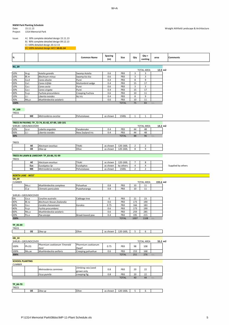
W+A
NWM Park Planting Schedule
Date: 15.11.13 Wraight Athfield Landscape & Architecture
Project: 1314 Memorial Park
Issue: A| 30% complete detailed design 15.11.13
B| 90% complete detailed design 09.12.13
C| 100% detailed design 20.12.13
D| 100% detailed design WCC 10.01.14
% Common NameSpacing
(m)Size Qty
Qty +
contingarea Comments
RG_09
TOTAL AREA 12.0 m2
10% As.g Astelia grandis Swamp Astelia 0.6 PB3 3 3
10% Bl.m Blechnum minus Swamp kio kio 0.6 PB3 3 3
10% Ca.d Carex dissita Purei 0.4 PB3 8 9
20% Ca.t Carex trifida Muttonbird sedge 0.4 PB3 15 17
10% Ca.s Carex secta Purei 0.6 PB3 3 3
20% Ca.v Carex virgata Purei 0.4 PB3 15 17
30% Fu.p Fuchsia procumbens Creeping Fuchsia 0.6 PB3 10 11
10% Li.i Libertia ixioides Nz Iris 0.4 PB3 8 9
30% Mu,a Muehlenbeckia axialaris 0.6 PB3 10 11
150% TOTAL 75 83 no.
TP_109
TREES
ME Metrosideros excelsa Pohutukawa as shown 1500L 1 1
TREES IN PAVING: TP_72‐74, 81‐82, 87‐89, 100‐101
SHRUB + GROUNDCOVER TOTAL AREA 14.2 m2
50% Lo.a Lobelia angulata Panakenake 0.4 PB3 44 48
50% Li.i Libertia ixioides New Zealand Iris 0.4 PB3 44 48
50% TOTAL 88 96 no.
TREES
AE Alectryon excelsus Titoki as shown 120‐160L 2 2y
OE Olea sp Olive as shown 120‐160L 8 9
TREES IN LAWN & LIMECHIP: TP_83‐86, 91‐99
TREES
AE Alectryon excelsus Titoki as shown 120‐160L 7 8
Euc Eucalyptus Sp Eucalyptus as shown by others 4 4 Supplied by others
ME Metrosideros excelsa Pohutukawa as shown 1500L 2 2
GB_09
CLIMBER TOTAL AREA 155.6 m2
Mu.c Muehlenbeckia complexa Pohuehue 0.8 PB3 10 11
Cl.p Clematis paniculata Puawhananga 0.8 PB3 10 11
SHRUB + GROUNDCOVER
0% Co.a Coryline australis Cabbage tree 0 PB3 21 23
40% Bl.nz Blechnum Novae Zealandia 0.6 PB3 173 190
60% Co.c Corokia cheesemanii Korokio 0.75 PB3 166 183
40% Fu.p Fuchia procumbens 0.6 PB3 173 190
60% Mu.a Muehlenbeckia axialaris 0.6 PB3 259 285
20% Po.a Poa anceps Broad‐leaved poa 0.4 PB3 195 215
220% TOTAL 1007 1108 no.
TP_45‐49
TREES
OE Olea sp Olive as shown 120‐160L 5 6
GB_10
SHRUB + GROUNDCOVER TOTAL AREA 55.2 m2
100% Ph.EGPhormium cookianum 'Emerald
Gem'
Phormium cookianum
Dwarf 0.75 PB3 98 108
100% Mu.ax Muehlenbeckia axillaris Creeping pohuehue 0.6 PB3 153 168
200% TOTAL 251 276 no.
SCHOOL PLANTING
CLIMBER
Metrosideros carminea climbing rata (seed
grown only0.8 PB3 20 22
Ficus pumila creeping fig 0.8 PB3 20 22
TOTAL 40 44 no.
TP_66‐70
TREES
OE Olea sp Olive as shown 120‐160L 5 6
NORTH LANE ‐ WEST
P:\1314 Memorial Park\08doc\MP-11-Plant Schedule.xls 5

W+A
NWM Park Planting Schedule
Date: 15.11.13 Wraight Athfield Landscape & Architecture
Project: 1314 Memorial Park
Issue: A| 30% complete detailed design 15.11.13
B| 90% complete detailed design 09.12.13
C| 100% detailed design 20.12.13
D| 100% detailed design WCC 10.01.14
% Common NameSpacing
(m)Size Qty
Qty +
contingarea Comments
RG_10 DELETED
TOTAL AREA m2
0% Ca.so Carex solandri 0.4 PB3 0 0
0% Ca.v Carex virgata Purei 0.4 PB3 0 0
0% Bl.m Blechnum minus swamp kiokio 0.4 PB3 0 0
0% Le.WK Leptospermum 'Wiri Kerry' 0.4 PB3 0 0
0% Le.SF Leptospermum 'Snow flurry' 0.4 PB3 0 0
0% TOTAL 0 0 no.
RG_11
TOTAL AREA 104.3 m2
30% Ca.so Carex solandri 0.4 PB3 196 216
30% Ca.v Carex virgata Purei 0.4 PB3 196 216
20% Bl.m Blechnum minus swamp kiokio 0.6 PB3 58 64
25% Le.WK Leptospermum 'Wiri Kerry' 0.75 PB3 46 51
25% Le.SF Leptospermum 'Snow flurry' 0.75 PB3 46 51
40% Ma.r Mazus radicans swamp musk 0.6 PB3 116 128
170% TOTAL 658 726 no.
TP_50‐65
TREES
OE Olea sp Olive as shown 120‐160L 16 18
RG_12_
TOTAL AREA 9.8 m2
0% Ca.so Carex solandri 0 PB3
0% Ca.v Carex virgata Purei 0 PB3
0% Bl.m Blechnum minus swamp kiokio 0 PB3
0% Le.WK Leptospermum 'Wiri Kerry' 0 PB3
0% Le.SF Leptospermum 'Snow flurry' 0 PB3
0% TOTAL 0 0 no.
TP_71
TREES
OE Olea sp Olive as shown 120‐160L 1 1
RG_13
TOTAL AREA 15.6 m2
0% Ca.so Carex solandri 0 PB3
0% Ca.v Carex virgata Purei 0 PB3
0% Bl.m Blechnum minus swamp kiokio 0 PB3
0% Le.WK Leptospermum 'Wiri Kerry' 0 PB3
0% Le.SF Leptospermum 'Snow flurry' 0 PB3
0% TOTAL 0 0 no.
TREES IN PAVING: TP_41‐44
SHRUB + GROUNDCOVER TOTAL AREA 11.0 m2
50% Li.i Libertia ixioides New Zealand Iris 0.4 PB3 34 37
50% Lo.a Lobelia angulata Panakenake 0.4 PB3 34 37
50% TOTAL 68 74 no.
TREES
OE Olea sp Olive as shown 120‐160L 4 4
GB_11
SHRUB + GROUNDCOVER TOTAL AREA 11.7 m2
50% Me.cMetrosideros carminea 'Red
carpet'0.6 PB3 16 18
60% Po.c Poa colensoi Blue tussock 0.4 PB3 44 48
50% Li.m Linum monogynum Native Linen 0.6 PB3 16 18
160% TOTAL 76 84 no.
TP_102
TREES
ME Metrosideros excelsa Pohutukawa as shown 1500L 1 1
TANGATA WHENUA GARDENS / MASSEY ENTRANCE
P:\1314 Memorial Park\08doc\MP-11-Plant Schedule.xls 6
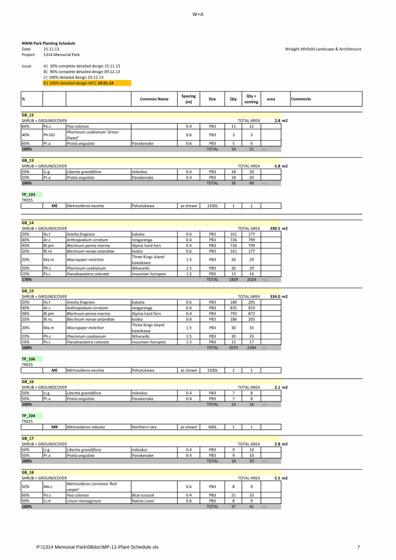
W+A
NWM Park Planting Schedule
Date: 15.11.13 Wraight Athfield Landscape & Architecture
Project: 1314 Memorial Park
Issue: A| 30% complete detailed design 15.11.13
B| 90% complete detailed design 09.12.13
C| 100% detailed design 20.12.13
D| 100% detailed design WCC 10.01.14
% Common NameSpacing
(m)Size Qty
Qty +
contingarea Comments
GB_12
SHRUB + GROUNDCOVER TOTAL AREA 2.8 m2
60% Po.c Poa colensoi 0.4 PB3 11 12
40% Ph.GDPhormium cookianum 'Green
Dwarf'0.6 PB3 3 3
60% Pr.a Pratia angulata Panakenake 0.6 PB3 5 6
160% TOTAL 19 21 no.
GB_13
SHRUB + GROUNDCOVER TOTAL AREA 5.8 m2
50% Li.g Libertia grandiflora mikoikoi 0.4 PB3 18 20
50% Pr.a Pratia angulata Panakenake 0.4 PB3 18 20
100% TOTAL 36 40 no.
TP_103
TREES
ME Metrosideros excelsa Pohutukawa as shown 1500L 1 1
GB_14
SHRUB + GROUNDCOVER TOTAL AREA 290.5 m2
20% As.f Astelia fragrans kakaha 0.6 PB3 161 177
40% Ar.c Arthropodium cirratum rengarenga 0.4 PB3 726 799
40% Bl.pm Blechnum penna marina Alpine hard fern 0.4 PB3 726 799
20% Bl.nz Blechnum novae‐zelandiae kiokio 0.6 PB3 161 177
20% Ma.m Macropiper melchiorThree Kings Island
kawakawa1.5 PB3 26 29
20% Ph.c Phormium cookianum Wharariki 1.5 PB3 26 29
10% Ps.c Pseudowiatera colorata mountain horopito 1.5 PB3 13 14
170% TOTAL 1839 2024 no.
GB_15
SHRUB + GROUNDCOVER TOTAL AREA 334.0 m2
20% As.f Astelia fragrans kakaha 0.6 PB3 186 205
40% Ar.c Arthropodium cirratum rengarenga 0.4 PB3 835 919
38% Bl.pm Blechnum penna marina Alpine hard fern 0.4 PB3 793 872
20% Bl.nz Blechnum novae‐zelandiae kiokio 0.6 PB3 186 205
20% Ma.m Macropiper melchiorThree Kings Island
kawakawa1.5 PB3 30 33
20% Ph.c Phormium cookianum Wharariki 1.5 PB3 30 33
10% Ps.c Pseudowiatera colorata mountain horopito 1.5 PB3 15 17
168% TOTAL 2075 2284 no.
TP_106
TREES
ME Metrosideros excelsa Pohutukawa as shown 1500L 1 1
GB_16
SHRUB + GROUNDCOVER TOTAL AREA 2.1 m2
50% Li.g Libertia grandiflora mikoikoi 0.4 PB3 7 8
50% Pr.a Pratia angulata Panakenake 0.4 PB3 7 8
100% TOTAL 14 16 no.
TP_104
TREES
MR Metrosideros robusta Northern rata as shown 400L 1 1
GB_17
SHRUB + GROUNDCOVER TOTAL AREA 2.8 m2
50% Li.g Libertia grandiflora mikoikoi 0.4 PB3 9 10
50% Pr.a Pratia angulata Panakenake 0.4 PB3 9 10
100% TOTAL 18 20 no.
GB_18
SHRUB + GROUNDCOVER TOTAL AREA 5.5 m2
50% Me.cMetrosideros carminea 'Red
carpet'0.6 PB3 8 9
60% Po.c Poa colensoi Blue tussock 0.4 PB3 21 23
50% Li.m Linum monogynum Native Linen 0.6 PB3 8 9
160% TOTAL 37 41 no160% TOTAL 37 41 no.
P:\1314 Memorial Park\08doc\MP-11-Plant Schedule.xls 7

W+A
NWM Park Planting Schedule
Date: 15.11.13 Wraight Athfield Landscape & Architecture
Project: 1314 Memorial Park
Issue: A| 30% complete detailed design 15.11.13
B| 90% complete detailed design 09.12.13
C| 100% detailed design 20.12.13
D| 100% detailed design WCC 10.01.14
% Common NameSpacing
(m)Size Qty
Qty +
contingarea Comments
GB_19
SHRUB + GROUNDCOVER TOTAL AREA 8.0 m2
60% Po.c Poa colensoi 0.4 PB3 30 33
40% Ph.GDPhormium cookianum 'Green
Dwarf'0.6 PB3 9 10
60% Pr.a Pratia angulata Panakenake 0.6 PB3 13 14
160% TOTAL 52 57 no.
TP_105
TREES
ME Metrosideros excelsa Pohutukawa as shown 1500L 1 1
GB_20
SHRUB + GROUNDCOVER TOTAL AREA 2.0 m2
60% Po.c Poa colensoi 0.4 PB3 8 9
40% Ph.GDPhormium cookianum 'Green
Dwarf'0.6 PB3 2 2
60% Pr.a Pratia angulata Panakenake 0.6 PB3 3 3
160% TOTAL 13 14 no.
GB_21
SHRUB + GROUNDCOVER TOTAL AREA 112.7 m2
60% Ar.c Arthropodium cirratum rengarenga 0.4 PB3 423 465
BUCKLE ST ‐ EAST
p g g
40% Ph.c Phormium cookianum Wharariki 1.5 PB3 20 22
60% Mu.a Muehlenbeckia astonii Shrubby tororaro 0.6 PB3 188 207
20% Pr.a Pratia angulata Panakenake 0.6 PB3 63 69
180% TOTAL 694 763 no.
TP_114
TREES
ME Metrosideros excelsa Pohutukawa as shown 200L 1 1
GB_22
SHRUB + GROUNDCOVER TOTAL AREA 65.5 m2
60% Ar.c Arthropodium cirratum rengarenga 0.4 PB3 246 271
40% Ph.c Phormium cookianum Wharariki 1.5 PB3 12 13
60% Mu.a Muehlenbeckia astonii Shrubby tororaro 0.6 PB3 109 120
20% Pr.a Pratia angulata Panakenake 0.6 PB3 36 40
180% TOTAL 403 444 no.
RG_14
TOTAL AREA 190.0 m2
10% As.g Astelia grandis Swamp Astelia 0.6 PB3 53 58
10% Bl.m Blechnum minus Swamp kio kio 0.6 PB3 53 58
10% Ca.d Carex dissita Purei 0.4 PB3 119 131
20% Ca.t Carex trifida Muttonbird sedge 0.4 PB3 238 262
10% Ca.s Carex secta Purei 0.6 PB3 53 58
20% Ca.v Carex virgata Purei 0.4 PB3 238 262
30% Fu.p Fuchsia procumbens Creeping Fuchsia 0.6 PB3 158 174
10% Li.i Libertia ixioides Nz Iris 0.4 PB3 119 131
30% Mu,a Muehlenbeckia axialaris 0.6 PB3 158 174
150% TOTAL 1189 1308 no.
TP_110‐113
TREES
ME Metrosideros excelsa Pohutukawa as shown 1500L 4 4
TP_115
SHRUB + GROUNDCOVER TOTAL AREA 3.3 m2
60% Po.c Poa colensoi 0.4 PB3 12 13
40% Ph.GDPhormium cookianum 'Green
Dwarf'0.6 PB3 4 4
60% Pr.a Pratia angulata Panakenake 0.6 PB3 6 7
160% TOTAL 22 24 no.
TREES
ME Metrosideros excelsa Pohutukawa as shown 200L 1 1
P:\1314 Memorial Park\08doc\MP-11-Plant Schedule.xls 8
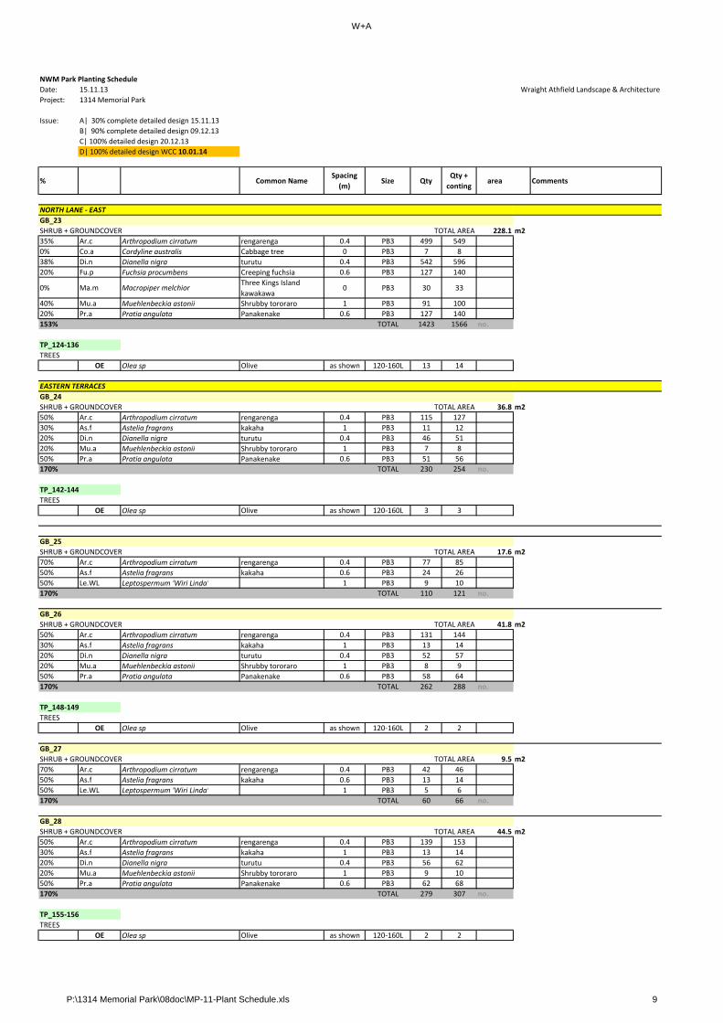
W+A
NWM Park Planting Schedule
Date: 15.11.13 Wraight Athfield Landscape & Architecture
Project: 1314 Memorial Park
Issue: A| 30% complete detailed design 15.11.13
B| 90% complete detailed design 09.12.13
C| 100% detailed design 20.12.13
D| 100% detailed design WCC 10.01.14
% Common NameSpacing
(m)Size Qty
Qty +
contingarea Comments
GB_23
SHRUB + GROUNDCOVER TOTAL AREA 228.1 m2
35% Ar.c Arthropodium cirratum rengarenga 0.4 PB3 499 549
0% Co.a Cordyline australis Cabbage tree 0 PB3 7 8
38% Di.n Dianella nigra turutu 0.4 PB3 542 596
20% Fu.p Fuchsia procumbens Creeping fuchsia 0.6 PB3 127 140
0% Ma.m Macropiper melchiorThree Kings Island
kawakawa0 PB3 30 33
40% Mu.a Muehlenbeckia astonii Shrubby tororaro 1 PB3 91 100
20% Pr.a Pratia angulata Panakenake 0.6 PB3 127 140
153% TOTAL 1423 1566 no.
TP_124‐136
TREES
OE Olea sp Olive as shown 120‐160L 13 14
GB_24
SHRUB + GROUNDCOVER TOTAL AREA 36.8 m2
50% Ar.c Arthropodium cirratum rengarenga 0.4 PB3 115 127
30% As.f Astelia fragrans kakaha 1 PB3 11 12
20% Di.n Dianella nigra turutu 0.4 PB3 46 51
20% Mu.a Muehlenbeckia astonii Shrubby tororaro 1 PB3 7 8
50% Pr.a Pratia angulata Panakenake 0.6 PB3 51 56
NORTH LANE ‐ EAST
EASTERN TERRACES
g
170% TOTAL 230 254 no.
TP_142‐144
TREES
OE Olea sp Olive as shown 120‐160L 3 3
GB_25
SHRUB + GROUNDCOVER TOTAL AREA 17.6 m2
70% Ar.c Arthropodium cirratum rengarenga 0.4 PB3 77 85
50% As.f Astelia fragrans kakaha 0.6 PB3 24 26
50% Le.WL Leptospermum 'Wiri Linda' 1 PB3 9 10
170% TOTAL 110 121 no.
GB_26
SHRUB + GROUNDCOVER TOTAL AREA 41.8 m2
50% Ar.c Arthropodium cirratum rengarenga 0.4 PB3 131 144
30% As.f Astelia fragrans kakaha 1 PB3 13 14
20% Di.n Dianella nigra turutu 0.4 PB3 52 57
20% Mu.a Muehlenbeckia astonii Shrubby tororaro 1 PB3 8 9
50% Pr.a Pratia angulata Panakenake 0.6 PB3 58 64
170% TOTAL 262 288 no.
TP_148‐149
TREES
OE Olea sp Olive as shown 120‐160L 2 2
GB_27
SHRUB + GROUNDCOVER TOTAL AREA 9.5 m2
70% Ar.c Arthropodium cirratum rengarenga 0.4 PB3 42 46
50% As.f Astelia fragrans kakaha 0.6 PB3 13 14
50% Le.WL Leptospermum 'Wiri Linda' 1 PB3 5 6
170% TOTAL 60 66 no.
GB_28
SHRUB + GROUNDCOVER TOTAL AREA 44.5 m2
50% Ar.c Arthropodium cirratum rengarenga 0.4 PB3 139 153
30% As.f Astelia fragrans kakaha 1 PB3 13 14
20% Di.n Dianella nigra turutu 0.4 PB3 56 62
20% Mu.a Muehlenbeckia astonii Shrubby tororaro 1 PB3 9 10
50% Pr.a Pratia angulata Panakenake 0.6 PB3 62 68
170% TOTAL 279 307 no.
TP_155‐156
TREESTREES
OE Olea sp Olive as shown 120‐160L 2 2
P:\1314 Memorial Park\08doc\MP-11-Plant Schedule.xls 9
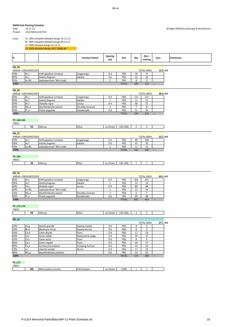
W+A
NWM Park Planting Schedule
Date: 15.11.13 Wraight Athfield Landscape & Architecture
Project: 1314 Memorial Park
Issue: A| 30% complete detailed design 15.11.13
B| 90% complete detailed design 09.12.13
C| 100% detailed design 20.12.13
D| 100% detailed design WCC 10.01.14
% Common NameSpacing
(m)Size Qty
Qty +
contingarea Comments
GB_29
SHRUB + GROUNDCOVER TOTAL AREA 15.9 m2
70% Ar.c Arthropodium cirratum rengarenga 0.4 PB3 70 77
50% As.f Astelia fragrans kakaha 0.6 PB3 22 24
50% Le.WL Leptospermum 'Wiri Linda' 1 PB3 8 9
170% TOTAL 100 110 no.
GB_30
SHRUB + GROUNDCOVER TOTAL AREA 36.9 m2
50% Ar.c Arthropodium cirratum rengarenga 0.4 PB3 115 127
30% As.f Astelia fragrans kakaha 1 PB3 11 12
20% Di.n Dianella nigra turutu 0.4 PB3 46 51
20% Mu.a Muehlenbeckia astonii Shrubby tororaro 1 PB3 7 8
50% Pr.a Pratia angulata Panakenake 0.6 PB3 51 56
170% TOTAL 230 254 no.
TP_164‐165
TREES
OE Olea sp Olive as shown 120‐160L 2 2
GB_31
SHRUB + GROUNDCOVER TOTAL AREA 22.7 m2
70% Ar.c Arthropodium cirratum rengarenga 0.4 PB3 99 109
50% As.f Astelia fragrans kakaha 0.6 PB3 32 35
50% Le.WL Leptospermum 'Wiri Linda' 1 PB3 11 12p p
170% TOTAL 142 156 no.
TP_163
TREES
OE Olea sp Olive as shown 120‐160L 1 1
GB_32
SHRUB + GROUNDCOVER TOTAL AREA 64.2 m2
50% Ar.c Arthropodium cirratum rengarenga 0.4 PB3 201 221
20% As.f Astelia fragrans kakaha 1 PB3 13 14
20% Di.n Dianella nigra turutu 0.4 PB3 80 88
20% Le.WL Leptospermum 'Wiri Linda' 1 PB3 13 14
10% Mu.a Muehlenbeckia astonii Shrubby tororaro 1 PB3 6 7
50% Pr.a Pratia angulata Panakenake 0.6 PB3 89 98
170% TOTAL 402 442 no.
TP_172‐174
TREES
OE Olea sp Olive as shown 120‐160L 3 3
RG_15
TOTAL AREA 27.1 m2
10% As.g Astelia grandis Swamp Astelia 0.6 PB3 8 9
10% Bl.m Blechnum minus Swamp kio kio 0.6 PB3 8 9
10% Ca.d Carex dissita Purei 0.4 PB3 17 19
20% Ca.t Carex trifida Muttonbird sedge 0.4 PB3 34 37
10% Ca.s Carex secta Purei 0.6 PB3 8 9
20% Ca.v Carex virgata Purei 0.4 PB3 34 37
30% Fu.p Fuchsia procumbens Creeping Fuchsia 0.6 PB3 23 25
10% Li.i Libertia ixioides Nz Iris 0.4 PB3 17 19
30% Mu,a Muehlenbeckia axialaris 0.6 PB3 23 25
150% TOTAL 172 189 no.
TP_117
TREES
ME Metrosideros excelsa Pohutukawa as shown 1500L 1 1
P:\1314 Memorial Park\08doc\MP-11-Plant Schedule.xls 10

W+A
NWM Park Planting Schedule
Date: 15.11.13 Wraight Athfield Landscape & Architecture
Project: 1314 Memorial Park
Issue: A| 30% complete detailed design 15.11.13
B| 90% complete detailed design 09.12.13
C| 100% detailed design 20.12.13
D| 100% detailed design WCC 10.01.14
% Common NameSpacing
(m)Size Qty
Qty +
contingarea Comments
RG_16
TOTAL AREA 26.1 m2
10% As.g Astelia grandis Swamp Astelia 0.6 PB3 7 8
10% Bl.m Blechnum minus Swamp kio kio 0.6 PB3 7 8
10% Ca.d Carex dissita Purei 0.4 PB3 16 18
20% Ca.t Carex trifida Muttonbird sedge 0.4 PB3 33 36
10% Ca.s Carex secta Purei 0.6 PB3 7 8
20% Ca.v Carex virgata Purei 0.4 PB3 33 36
30% Fu.p Fuchsia procumbens Creeping Fuchsia 0.6 PB3 22 24
10% Li.i Libertia ixioides Nz Iris 0.4 PB3 16 18
30% Mu,a Muehlenbeckia axialaris 0.6 PB3 22 24
150% TOTAL 163 180 no.
TP_118
TREES
ME Metrosideros excelsa Pohutukawa as shown 1500L 1 1
RG_17
TOTAL AREA 33.3 m2
10% As.g Astelia grandis Swamp Astelia 0.6 PB3 9 10
10% Bl.m Blechnum minus Swamp kio kio 0.6 PB3 9 10
10% Ca.d Carex dissita Purei 0.4 PB3 21 23
20% Ca.t Carex trifida Muttonbird sedge 0.4 PB3 42 46
10% Ca.s Carex secta Purei 0.6 PB3 9 10
20% Ca.v Carex virgata Purei 0.4 PB3 42 46g
30% Fu.p Fuchsia procumbens Creeping Fuchsia 0.6 PB3 28 31
10% Li.i Libertia ixioides Nz Iris 0.4 PB3 21 23
30% Mu,a Muehlenbeckia axialaris 0.6 PB3 28 31
150% TOTAL 209 230 no.
TP_119
TREES
ME Metrosideros excelsa Pohutukawa as shown 1500L 1 1
RG_18
TOTAL AREA 39.6 m2
10% As.g Astelia grandis Swamp Astelia 0.6 PB3 11 12
10% Bl.m Blechnum minus Swamp kio kio 0.6 PB3 11 12
10% Ca.d Carex dissita Purei 0.4 PB3 25 28
20% Ca.t Carex trifida Muttonbird sedge 0.4 PB3 50 55
10% Ca.s Carex secta Purei 0.6 PB3 11 12
20% Ca.v Carex virgata Purei 0.4 PB3 50 55
30% Fu.p Fuchsia procumbens Creeping Fuchsia 0.6 PB3 33 36
10% Li.i Libertia ixioides Nz Iris 0.4 PB3 25 28
30% Mu,a Muehlenbeckia axialaris 0.6 PB3 33 36
150% TOTAL 249 274 no.
TP_120
TREES
ME Metrosideros excelsa Pohutukawa as shown 1500L 1 1
RG_19
TOTAL AREA 34.8 m2
10% As.g Astelia grandis Swamp Astelia 0.6 PB3 10 11
10% Bl.m Blechnum minus Swamp kio kio 0.6 PB3 10 11
10% Ca.d Carex dissita Purei 0.4 PB3 22 24
20% Ca.t Carex trifida Muttonbird sedge 0.4 PB3 44 48
10% Ca.s Carex secta Purei 0.6 PB3 10 11
20% Ca.v Carex virgata Purei 0.4 PB3 44 48
30% Fu.p Fuchsia procumbens Creeping Fuchsia 0.6 PB3 29 32
10% Li.i Libertia ixioides Nz Iris 0.4 PB3 22 24
30% Mu,a Muehlenbeckia axialaris 0.6 PB3 29 32
150% TOTAL 220 241 no.
TP_121
TREES
ME Metrosideros excelsa Pohutukawa as shown 1500L 1 1
P:\1314 Memorial Park\08doc\MP-11-Plant Schedule.xls 11
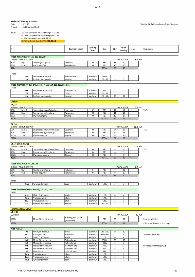
W+A
NWM Park Planting Schedule
Date: 15.11.13 Wraight Athfield Landscape & Architecture
Project: 1314 Memorial Park
Issue: A| 30% complete detailed design 15.11.13
B| 90% complete detailed design 09.12.13
C| 100% detailed design 20.12.13
D| 100% detailed design WCC 10.01.14
% Common NameSpacing
(m)Size Qty
Qty +
contingarea Comments
TREES IN PAVING: TP_116, 122‐123, 157
SHRUB + GROUNDCOVER TOTAL AREA 5.6 m2
50% Li.g Libertia grandiflora mikoikoi 0.4 PB3 18 20
50% Pr.a Pratia angulata Panakenake 0.4 PB3 18 20
50% TOTAL 36 40 no.
TREES
ME Metrosideros excelsa Pohutukawa as shown 1500L 1 1
SM Sophora microphylla Kowhai as shown 120‐160L 3 3
TREES IN LAWN: TP_137‐141, 145‐147, 150‐154, 158‐162, 166‐171
TREES
MR Metrosideros robusta Northern rata as shown 45L 3 3
OE Olea sp Olive as shown 120‐160L 1 1
SM Sophora microphylla Kowhai as shown 120‐160L 20 22
GB_33
SHRUB + GROUNDCOVER TOTAL AREA 5.5 m2
50% La.a.G Lavandula augustifolia Grosso Lavender 0.5 PB3 11 12 TBC
50% Ro.o Rosmarinus officinalis sp Rosemary 0.5 PB3 11 12
100% Th.v Thymus vulgaris Thyme 0.6 PB3 15 17
200% TOTAL 37 41 no.
GB_34
CRECHE
_
SHRUB + GROUNDCOVER TOTAL AREA 12.0 m2
50% La.a.G Lavandula augustifolia Grosso Lavender 0.5 PB3 24 26 TBC
50% Ro.o Rosmarinus officinalis sp Rosemary 0.5 PB3 24 26
100% Th.v Thymus vulgaris Thyme 0.6 PB3 33 36
200% TOTAL 81 88 no.
GB_35 (a,b,c,d,e,f,g)
SHRUB + GROUNDCOVER TOTAL AREA 2.5 m2
50% La.a.G Lavandula augustifolia Grosso Lavender 0.4 PB3 8 9 TBC
50% Ro.o Rosmarinus officinalis sp Rosemary 0.4 PB3 8 9
100% Th.s Thymus serpyllum Thyme 0.6 PB3 7 8
200% TOTAL 23 26 no.
SHRUB + GROUNDCOVER TOTAL AREA 2.8 m2
50% Li.g Libertia grandiflora mikoikoi 0.4 PB3 9 10
50% Pr.a Pratia angulata Panakenake 0.4 PB3 9 10
50% TOTAL 18 20 no.
TREES
Py.c Pyrus conference pear as shown 120L 2 2
TREES
M.co Malus Cox's pippin apple as shown 120L 4 4
Pr.h Prunus hawera plum as shown 120L 2 2
Pr.s Prunus santa rosa plum as shown 120L 2 2
SM Sophora microphylla Kowhai as shown 120‐160L 1 1
UP_1‐13
CLIMBER TOTAL AREA TBC m2
100% Metrosideros carminea climbing rata (seed
grown onlyPB3 30 33 2no. per planter
100% TOTAL 30 33 no. + 2 each side west portal steps
AE Alectryon excelsus Titoki as shown 120‐160L 9 10
Euc Eucalyptus sp Eucalyptus as shown by others 4 4 Supplied by others
M.co Malus Cox's pippin apple as shown 120L 4 4
ME Metrosideros excelsa Pohutukawa as shown 1500L 29 32
ME Metrosideros excelsa Pohutukawa as shown 200L 2 2
MR Metrosideros robusta Northern rata as shown 400L 1 1 Supplied by others (WCC)
MR Metrosideros robusta Northern rata as shown 45L 4 4
UNDERPASS PLANTING
TREES IN PAVING: TP_183‐184
TREE TOTALS
TREES IN LAWN & LIMECHIP: TP_175‐182, 185
PB Pinus brutia Gallipoli pine as shown TBC 1 1
Pr.h Prunus hawera plum as shown 120L 2 2
Pr.s Prunus santa rosa plum as shown 120L 2 2
Py.c Pyrus conference pear as shown 120L 2 2
P:\1314 Memorial Park\08doc\MP-11-Plant Schedule.xls 12

W+A
NWM Park Planting Schedule
Date: 15.11.13 Wraight Athfield Landscape & Architecture
Project: 1314 Memorial Park
Issue: A| 30% complete detailed design 15.11.13
B| 90% complete detailed design 09.12.13
C| 100% detailed design 20.12.13
D| 100% detailed design WCC 10.01.14
% Common NameSpacing
(m)Size Qty
Qty +
contingarea Comments
OE Olea sp Olive as shown 120‐160L 98 108
SM Sophora microphylla Kowhai as shown 120‐160L 24 26
UP Ulnus parvifolia Chinese Elm as shown 120‐160L 3 3
TOTAL 185 201 no.
P:\1314 Memorial Park\08doc\MP-11-Plant Schedule.xls 13