memo to: operations group subject: pad for loading front
TRANSCRIPT
Memo to: Operations GroupFrom: T. Weadon, G. Lawrence, F. Crews
Subject: Pad for Loading Front Ends, -atid GBTACeess 'Ramp
At the last operations meeting, the 3 of us were assigned the task of clarifying andrecommending:
I) Pad for setting up front endson the ground prior to lifting to the base of the feedarm by GBT hoist #2. This pad
was previously sized at 40 ft 2 , with a shed for housing a cryogenics compressor, avacuum pump, and tools- including slings, and necessary hand tools. After looking atthe area, and considering installations, we come to the following conclusions.
A) Cut the size of the pad to 20 ft. by 20 ft. If need be in the future, increasing thesize would be no problem.
B)Eliminate the shed, but an area to have a cryogenics compressor, vacuum pump,and some hand tools needs to be provided at the GBT. The use of this area should notrequire that the front end be removed from the truck. The reasons that we eliminatethe shed on the pad is fear of ice falling from the structure that could damage theshed, the cost of building the shed, and running electricity out to it. The approximaterequired time to lift a front end into the feed room on top when the refrigerator canagain cool is as follows:
Unloading and rigging on ground- estimated ...................................... 8 min.Time on hoist #2- 160ft/49 (hoist speed per minute) ........................ 3 25min.Release spreader from hoist and move to manlift #2- estimate ......... 5 min.Trip up on manlift #2- 216 ft/106 (speed per minute) ....................... 2 min.Moving at top, and cryogenic lines connected again- estimated...... 10 min.
Total time from arrival at the GBT before the unit can again be cooled is thus 28.25min. (in absence of "tweaking" at GBT site). To this must be added the time from cryolines disconnect at lab to arrival at GBT site which has been determined to be about 20min. The total time then is 48 min., and may be in error either way.
The rule of thumb used by Roger Norrod and others is that loss of cryogenics for 45minutes is about the time after which front ends require roughly 10 hours of pumping
1
and cool down. The time varies somewhat depending on whether the front end inquestion has just recently been warmed and cooled, or whether it has been cooled fora long time, and thus has contaminants due to outgassing.
C) Another storage concern has arisen. When the antenna is tilted, the unbalance ofweight distibuted around the feed turret axis of rotation by the various front ends canaffect the pointing. Thus, if front ends are removed from the feed turret, it may benecessary to install "dummy loads". It remains to be seen how often this will happen,but we expect it to happen as the telescope is commissioned during "first light". LeeKing insists that these loads not be stored on the tilting structure due to weightproblems. The bottom line is that there may well be a need to store "dummy loads"somewhere in a location that does not result in undue loss of time installing them. Agood possibility is to store them on the "on side" elevation bearing platform, becausefrom this location (remembering the antenna to be in the access position) they can bequickly wheeled to the feedarm manlift for installation. An alternative would be onthe ground somewhere, but it would not be desirable to load them onto a truck to getthem into position to be lifted by the feedarm hoist. In any event, a time effecientlocation needs to be provided.
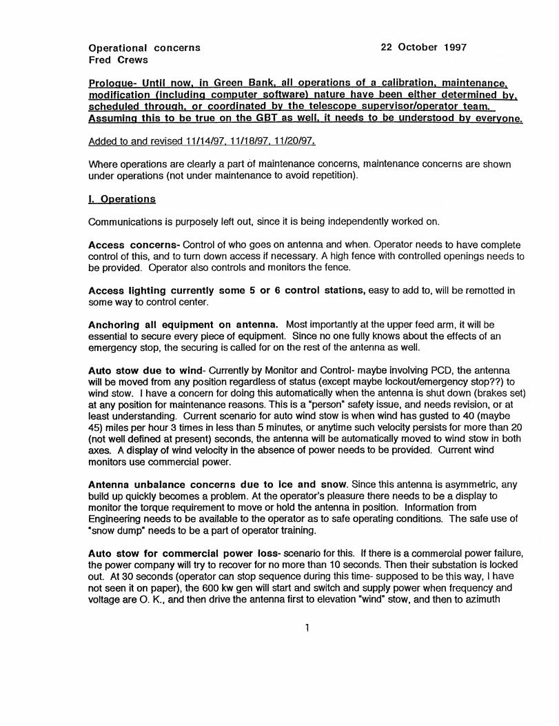
II) The second issueinvolves the ramp for loading/unloading equipment which we feel is essential. Referto the attached sheet, which is a cut from RSI drawing 121011 sheet 1 Rev. Coriginally from Win). The antenna alidade access was specifically designed for theramp, and requires a ramp which is only about 44 inches above the existing groundlevel (to be level with the top of the az. track). Note that the first level access is 48inches above the az. rack.
NRAO trucks used to deliver equipment to telescopes were measured and found to be45-48 inches from ground level to bed level. At this level, equipment is rolled off thetruck onto the telescope and placed on the manlift to take it to level 2- elevation 170inches, which is the elevation of the servo room, cryogenics room, HVAC components,the substation and numerous transformers and switchgear. The above procedure isintended for racks and cryogenics compressors among other things.
The azimuth stow position is true 225 deg. This puts the ramp location at 135 deg.true azimuth, and the height of the ramp to be at the top of track level, or slightlyabove.
It is important to note that the ramp does not interfere with the motors and drivetrains of the antenna (incorrectly stated at the last operations meeting). They are wellabove the top of the ramp.
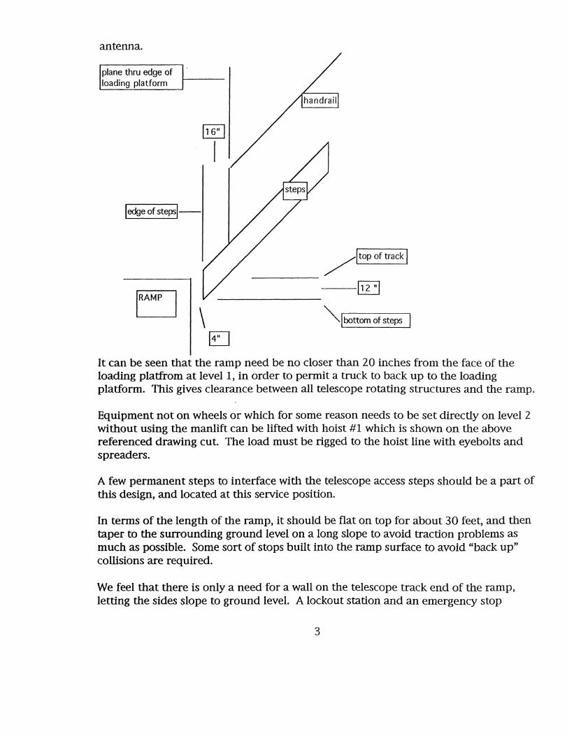
The sketch below is a sort of side view taken from actual measurements at the
2
Itop of track
112 ul
antenna.
plane thru edge ofloading platform
ledge of steps
'RAMP
Ibottom of steps
14"
It can be seen that the ramp need be no closer than 20 inches from the face of theloading platfrom at level 1, in order to permit a truck to back up to the loadingplatform. This gives clearance between all telescope rotating structures and the ramp.
Equipment not on wheels or which for some reason needs to be set directly on level 2without using the manlift can be lifted with hoist #1 which is shown on the abovereferenced drawing cut. The load must be rigged to the hoist line with eyebolts andspreaders.
A few permanent steps to interface with the telescope access steps should be a part ofthis design, and located at this service position.
In terms of the length of the ramp, it should be flat on top for about 30 feet, and thentaper to the surrounding ground level on a long slope to avoid traction problems asmuch as possible. Some sort of stops built into the ramp surface to avoid "back up"collisions are required.
We feel that there is only a need for a wall on the telescope track end of the ramp,letting the sides slope to ground level. A lockout station and an emergency stop
3

station needs to be provided. Perhaps the lockout station can be on the structure atthe access steps with the emergency stop on the ramp. For safety purposes, we feelresponsible for designing these lockouts, and will address this issue in a future memo..
File:gbtpad/rampl 1/10/97
4

PAW
S U
STA
SSY
DA
SH P
IO.
IMIN
I■1
0S
,..t
t-C V
ICO
VO
CH
T
FO
R B
ILL
OF
MATERIA
L —
SE
E S
H 3
5F
OR
DE
SIG
N O
NL
YI .„
, iva
m. I
arom
mA
rsoo
t OR
ligai
rAC
TISI
CR
RA
DA
•N
SY
S M
S I
NC
.TE
C1
1c&
PRO
CO
CT
S O
W.
VtR
=KA
AL
IDA
DE
AC
CE
SS
AN
D
EQ
UIP
BL
DG
IN
ST
L
°119"ab
1210
1!
WEI
GH
T T
ABL
E
r1D
QTY
EACH
TOTA
L
—01
1
,,
TE
O b
TE
O b
, TO
TAL
'WEI
CN
TT
O a
Pk* 0
.4 1
10e,
-1
CSIA
NTT
TY P
at A
SSY
11
1CA
RE R
O.Pa
ir N
J. O
R M
INT
IX
goaa
rnas
11111
1 DO
= D
O =
TM
Can
n' P
O m
a,
rum
saw
osA
0,1
14
CI
mom
%*xc
=w
ax
is V
IM =
MY
m
ac w
ing
Csv
o
HN
OC
TID
I MO
RT
OV
AA
CIZ
X =
OR
MiC
ff A
SS't
G14
=um
Am
ex
vs
3N
ME
MW
EN
TOVI
CT O
CWOR
SOMS
.72
07
01
14
11
11M
ii
AQ:0
100C
C XX
!!M
IS T
i430
,114
!Ig
e:*64
AE
L D
RIV
EA
=S
S L
EY
E3-
T30
.0
EQU
IPM
ENT
BU
ILD
ING
AC
CE
SS L
EV
EL
144.
0LO
AD
ING
PLA
TFO
R.1
T/TR
AC
XD
AT
UM
0.0
0
(39.
5 T
YP
)
FIN
ISH
GR
AC
E
Operational concerns 22 October 1997Fred Crews
Prot° ue- Until now in Green Bank all o erations of a calibration maintenancemodification (including computer software) nature have been either determined by scheduled throu • h or coordinated b the telesco • e su • ervisor/o • erator team.Assumin this to be true on the GBT as well it needs to be understood b ever one.
Added to and revised 11/14/97, 11118/97, 11/20/97.
Where operations are clearly a part of maintenance concerns, maintenance concerns are shownunder operations (not under maintenance to avoid repetition).
I. Operations
Communications is purposely left out, since it is being independently worked on.
Access concerns- Control of who goes on antenna and when. Operator needs to have completecontrol of this, and to turn down access if necessary. A high fence with controlled openings needs tobe provided. Operator also controls and monitors the fence.
Access lighting currently some 5 or 6 control stations, easy to add to, will be remotted insome way to control center.
Anchoring all equipment on antenna. Most importantly at the upper feed arm, it will beessential to secure every piece of equipment. Since no one fully knows about the effects of anemergency stop, the securing is called for on the rest of the antenna as well.
Auto stow due to wind- Currently by Monitor and Control- maybe involving PCD, the antennawill be moved from any position regardless of status (except maybe lockout/emergency stop??) towind stow. I have a concern for doing this automatically when the antenna is shut down (brakes set)at any position for maintenance reasons. This is a "person" safety issue, and needs revision, or atleast understanding. Current scenario for auto wind stow is when wind has gusted to 40 (maybe45) miles per hour 3 times in less than 5 minutes, or anytime such velocity persists for more than 20(not well defined at present) seconds, the antenna will be automatically moved to wind stow in bothaxes. A display of wind velocity in the absence of power needs to be provided. Current windmonitors use commercial power.
Antenna unbalance concerns due to ice and snow. Since this antenna is asymmetric, anybuild up quickly becomes a problem. At the operator's pleasure there needs to be a display tomonitor the torque requirement to move or hold the antenna in position. Information fromEngineering needs to be available to the operator as to safe operating conditions. The safe use o"snow dump" needs to be a part of operator training.
Auto stow for commercial power loss- scenario for this. If there is a commercial power failure,the power company will try to recover for no more than 10 seconds. Then their substation is lockedout. At 30 seconds (operator can stop sequence during this time- supposed to be this way, I havenot seen it on paper), the 600 kw gen will start and switch and supply power when frequency andvoltage are 0. K., and then drive the antenna first to elevation "wind" stow, and then to azimuth

"wind" stow. Afterward, receiving equipment, the manlifts, the feed room air handler blowers, andaccess lighting will be activated. Hopefully there will be no one on the tilting structure during stowtime- if so, they will just have to wait. Communications needs to be operational at all times. After theantenna is stowed, and all is secure, the operator can manually bring up the 50 kw generator andswitch to it, after which he can shut down the 600 kw generator. When commercial power isrestored, the operator or other designee switches back to commercial. There has been some talkabout automatically restoring commercial power, but this could be a disaster, and should beavoided.
Additional flood lighting. There need to be provided "off the antenna" flood lights controlledfrom the operations center as well as at the antenna as an operational and safety issue. This is not apart of the contract. Perhaps needs to be put on other lists.
Aircraft warning lights. Certain length of time failure requires notification of FAA. Thisparticularly involves the 2 flashing lights on top. One of these lights is slaved to the other since theymust operate in synchronism- a failure of the master will result in the slave being on all the time (notfl ashing.).
Emergency stops- At key locations, are located emergency stops. They are not to be confusedwith safety lockouts, and are not to be used indiscriminately. At present, no one really knows whathappens to the antenna when it undergoes an emergency stop. There is to be a pair of hardwires tothe Telescope Control Center, and other local and remote switches can be added.
Electrical safety lockouts. Some are distribution panel lockouts, some are individual breakerlockouts. For the most part, the use of these can be determined by using RSI drawing 121402,sheets 1 and 2.
Feed room turret can only be moved (rotated) when the antenna is in access stow. This is notsurvival stow, and not the "bird bath" position.
Installations (important to have hands free communications between ground, base of the feedarm, and upper feedarm elevator landings).
Dollies on which front ends and feeds are mounted need to be designed and provided. Equipmentis to be installed on the dollies prior to leaving the Lab, and the equipment will stay on the dolliesuntil they arrive at GBT focus area. Work on these designs should be in progress now.. DaveSeaman had given this a little thought, but I don't know if he dedicated anything to paper.
1. Prime focus front ends- Use of 2 hoists is required- Front ends and feeds should arrive attelescope on their side. The upper hoist used to install these front ends is to be supplied by NRAO.We are currently pushing RSI to provide suitable support for this hoist in the roof of the prime focusarea. When NRAO reviews RSI's proposal for the prime focus room, we should insist on as high aroof as possible to give head room to use this hoist. Installation of equipment into the prime focusmount is complicated by the stowed tilt of the mount. Dave Seaman, telescope mechanics, andmyself looked into this some years ago. Now it needs to be designed.
2. Turret front ends- Use of 2 hoists is required- Front ends and feeds should arrive at telescopevertical. RS1 supplied equipment for this appears to be under control- but it must be remembered
2
that prime focus front ends and top installed turret equipment must all move through the doorwayinto the prime focus area.
Laser Safety- Procedures for the protection of employees and visitors will need to be strictlyadhered to.
Limit switches- Antenna az and el limit switches- There are 2 sets of limit switches, and each setis redundant. An additional part of the azimuth limit switch configuration are switches that verify CWor CCW cable wrap. Limit number 1 can be backed out of by the operator. Limit number 2 requiresthat 2 people be in attendance. In addition there is a set of limit switches that prepare for stow pininsertion at each of the 5 stowing positions. I understand that PCD has provided a couple of optionsto certify that the antenna is correctly positioned, and the stow pin circuit is enabled.
Only, and only trained users are to operate the manlifts.
Provisions for the safe removal of an injured, ill or insecure person from the antenna.Equipment required. Personnel training required
Prime focus boom can be deployed and retracted in any elevation position. The boom maybe found in somebody's corn field in case of an emergency stop.
Quick graceful stop- A gracious stop needs to be provided that would stop the antenna now, butwould not put the antenna through all the stress of an emergency stop. This matter and it'simplementation needs to be discussed.
Sun avoidance- Tests conducted by Roger Norrod using Triangle #6 paint suggest that damageto the focal point area may occur if the GBT is too close to the sun. This is contrary to all of ourGreen Bank experience, and needs to again be independently verified by running tests on the 140ft. Perhaps a call to Ben Parvin at JPL is called for. If sun avoidance is required, a reasonablenumber of avoidance procedures must be implemented.
Truck ramp, and its safety, including lockout of antenna motion.
11. Maintenance Access to cable trays and external wiring-we have insisted on good access to all cabletrays. See Upper pintle bearing access.
Antenna integrity inspections. Recommend visual inspection of members, joints, and welds.Engineering should give operations a list of the most likely sections to fail.
Aircraft warning light access??? Not absolutely finalized for one of dish periphery lights.
Azimuth cable wrap- This is a major concern at the moment. Design is marginal. Two feeds of4160 site power are included in the wrap.
Elevation cable wrap. The technique provided by the contractor to protect and prevent unduewear on the cables is untested in Green Bank. Periodic visual inspection will be required.
3

Fiducials- These need to be established and maintained throughout the antenna both forconventional mensuration and laser ranging. It is upsetting and scary to be told by an astronomerthat pointing is wild, or not repeating. Finding the culprit can be a major problem. With the advent oflaser ranging absolute measurements developed for this antenna, we have a tool which can helpresolve the source of problems, and which with some study can suggest possible improvements tothe structure. The danger in all this is that one always studies the structure and never doesastronomy as in the early days of Haystack.
HVAC- System can be remotely monitored, temps set, and back-up chiller, and refrigerant pumpsswitched. During power outage there is provision for air flow through feed room airhandlers (nocooling). Unit will recover from power failure without reprogramming. May need a start switchpushed at alidade.
Load Bank- it is presently unclear as to what maintenance or inspection is required on this unit.
Laser systems and their testing, calibration, and reliability. This matter needs to bediscussed with the Laser group. They will definitely impact on scheduled maintenance periods.
Lower manlift tests and usage do not necessarily tie up the telescope. However, it needs to beremembered that the upper manlift can only be used when the antenna is in the access position,and it must be left at it's lowered position when the antenna is tilted.
Lubrication- There are many areas on the antenna that need periodic lubrication. RSI is toprovide recommended schedules and lubricants. So far, the extent of their recommendation is "seemanufacturer's recommendations". There are 2 areas that need attention that can fall through thecrack.
1) The trunnions or double pivoting plates on which the el drives mount have grease fittings, andwill need periodic attention. Because of the alemite fitting locations, these will be easy to overlook.
2) The individual drive couplings from the gear boxes need lubrication. These are accessedthrough a removable plate just in front of the gear box on each drive. Hargreaves is installingalemite fittings on each coupling.
Manlifts (both)- Requirement to test certain manlift safety features on short term recurring basis.Monthly test function of overspeed device, visually inspect, and check tube every 20 hours of use, ormonthly. Quarterly, coincident with monthly tests, drop test must be performed. RSI has beenrunning their own tests. On a 3 year basis, a safety part must be replaced for trade in of $3700. Ifnot traded in, price $6800.
Maintenance painting. This will be a major problem. Areas of the alidade can be worked onwith the antenna in operation. Not true of the tilting structure. What happened to the need for aportable personnel maintenance lift?
MG set- Will need periodic maintenance as described in instruction manual. Needs an elapsedtime meter installed.
Operational limits and azimuth direction of wrap switches need to be tested at least eve

other week.
Panel actuators- Current thinking seems to be (based on GB reliability testing) that aprogrammed maintenance schedule will not be required. That is that so few failures are anticipated,that failures should just be let go for a few years, and then a concentrated maintenance period set torepair all problems. Probably some experience based program will need to be instituted.Satisfactory performance of the antenna does not require all actuators operational. There is aprocedure to replace actuators from the top of the panels. Whether suspended walkways installedby RSI will be available is up in the air.
Subreflector- Someday down the road, the subreflector will have to come down. Some thoughtneeds to be put into this now, and particularly while the upper feed arm is being installed on theantenna. It does have a 3 point interface plate on the recommendation of Dave Seaman- but theproblem of removal and installation needs to be given some thought.
Subreflector Actuators- When one of these actuators is removed, the Stewart platform becomesunstable. The contractor is to provide suitable adjustable bars to be attached before removal of theactuator. These have not been seen. However, it would certainly be important for the NRAO tohave spare actuators of each type (maybe 3?) with motors/gear boxes and limit/readout boxesinstalled and calibrated to be inserted after removable of a bad actuator. This would not negate theneed for the temporary support bar, but would enable a quick recovery to the use of the subreflector.
Substation Maintenance- Substation has the auto transfer switch and timing unit to start 600 kwgenerator. The substation will require periodic exercise and inspections.
Special tools- Plans need to be made for special tools that will be required for the maintenanceof this antenna. One which comes to mind is a special dolly for use on el drives to remove themsince due to the counterweight, rigging can not be done from above. The az drives will needspecial rigging. Hargreaves has already removed an az drive with the aid of a special device thathe built. This needs to be preserved.
Track inspections- The track will be covered by tagalong dollies. Some dollies should have fulllength inspection ports to view the track without removing the dolly.
Upper manlift and commercial power failure. At the point of commercial power failure andauto stow, 1 am not sure what happens to the upper manlift. In other words, the upper manlift is upwhen power fails. Is this a question for RS1? Couldn't this be resolved by a rule that unless thereare special situations, no one is on tilting structure unless the antenna is in stow?
UPS supply supplied by PCD. This system is required for PCD equipment in the event ofcommercial power failure, and subsequent stowing of the antenna. It will require periodicinspection and maintenance.
Use and storage of "dummy frontends"- information currently on hand indicates that it may benecessary to maintain a certain balance of the loads in the turret, thus calling for dummy loads whensome front ends are removed. A method to determine this unbalance and a location to store theloads (not on the tilting structure says Lee King-) is called for. The necessity of placing andremoving these loads will impact on installation time.
5

600 and 50 kw generators- Require periodic maintenance and fairly frequent "freshening" offuel. Start up (off line) should be tested at least every other week. Both units contain batteries.
Upper feedarm machinery and its control. Currently, (even though tests continue), theseunits are unreliable, and monitors seem to have problems. We don't have enough experience toknow what is required.
Upper pintle bearing access. Bob Hall is still working with the contractor on this. Entire upperpintle house needs to be redone and access needs to be incorporated into the new design. NR AOwill probably have to design and construct this with the contractor installing it (my guess). Someoneto design this on the part of Green Bank is sorely needed. What is done will certainly impact onmaintenance. Hopefully a new design will allow for cable splicing terminations space.
File:Operco ncern sG BT 10/22/97