membrane separation technical analysis - pg&e, pacific gas ...• the gas equilibrium solubility...
TRANSCRIPT

PG&E GAS R&D AND INNOVATION
Membrane Separation Technical Analysis
6/15/2018

PG&E GAS R&D AND INNOVATION TECHNICAL ANALYSIS: MEMBRANE SEPARATION
PAGE 2 OF 18
“PG&E” refers to Pacific Gas and Electric Company, a subsidiary of PG&E Corporation. © 2019 Pacific Gas and Electric Company. All rights reserved.
“The opinions, findings, and conclusions in the whitepaper are those of the authors and not necessarily those of PG&E. Publication and dissemination of the whitepaper by PG&E should not be considered an endorsement by PG&E, or the accuracy or validity of any opinions, findings, or conclusions expressed herein.
In publishing this whitepaper, PG&E makes no warranty or representation, expressed or implied, with respect to the accuracy, completeness, usefulness, or fitness for purpose of the information contained herein, or that the use of any information, method, process, or apparatus disclosed in this whitepaper may not infringe on privately owned rights. PG&E assumes no liability with respect to the use of, or for damages resulting from the use of, any information, method, process, or apparatus disclosed in this report. By accepting the whitepaper and utilizing it, you agree to waive any and all claims you may have, resulting from your voluntary use of the whitepaper, against PG&E.”

PG&E GAS R&D AND INNOVATION TECHNICAL ANALYSIS: MEMBRANE SEPARATION
PAGE 3 OF 18
“PG&E” refers to Pacific Gas and Electric Company, a subsidiary of PG&E Corporation. © 2019 Pacific Gas and Electric Company. All rights reserved.
Table of Contents 1 What is Membrane Separation ....................................................................................................................................4
1.1 Methodology...................................................................................................................................................................... 4 1.2 Materials ............................................................................................................................................................................ 7 1.3 Module Type ...................................................................................................................................................................... 9 1.4 Design of Membrane Systems for Biogas Upgrading ......................................................................................................... 9
2 Membrane Separation Technologies ......................................................................................................................... 12 2.1 Additional Information - Publicly Available by Vendor .................................................................................................... 14
3 R&D Opportunities .................................................................................................................................................. 17 4 References .............................................................................................................................................................. 18
Table of Figures Figure 1 Literature data for CO2/CH4 ideal selectivity versus CO2 permeability (1991) ............................................................ 6
Table of Tables Table 1 Organic polymers and inorganic membrane materials ................................................................................................... 7 Table 2 Advantages and Disadvantages of inorganic membranes in comparison with polymeric membranes ......................... 8 Table 3 Comparison of hollow fiber, spiral wound, and envelope .............................................................................................. 9 Table 4 Various gas permeation upgrading processes are compared in terms of energy demand, CH4 recovery, required membrane area, and specific upgrading costs .......................................................................................................................... 11 Table 5 Comparison membrane area, methane losses and the cost items of membrane, gas absorption and hybrid process. (1 MM% = %106 USD)................................................................................................................................................................. 11 Table 8 Comparison and evaluation of the costs of different biogas upgrading technologies (Ref 1.1) ................................... 12 Table 6 Principal membrane suppliers for natural gas separation systems (Ref 1.1) ................................................................ 12 Table 7 Current commercial membrane materials and selectivities for separation of impurities from natural gas (Ref 1.1) .. 12

PG&E GAS R&D AND INNOVATION TECHNICAL ANALYSIS: MEMBRANE SEPARATION
PAGE 4 OF 18
“PG&E” refers to Pacific Gas and Electric Company, a subsidiary of PG&E Corporation. © 2019 Pacific Gas and Electric Company. All rights reserved.
1 What is Membrane Separation
1.1 METHODOLOGY Dissolution and diffusion into materials. A differential pressure across opposing sides of the film, provide for gas transport across the film (permeation). The rate of permeation is dependent upon the solubility coefficient and diffusion coefficient of the gas-membrane system. (Chen, Ramirez, Kaliaguine, Vinh, & Rodrigue, 2015) In general, permeability measures the membrane productivity. Selectivity sets the purity of the recovered gas. It refers to the membranes ability to “select” particular molecules for passing through (e.g. CH4) and for preventing others from passing through (e.g. CO2). (Xia, 2018) ‘Solution-diffusion’ theory can be used to describe the mechanism of polymer membrane gas separations. Permeation consists of two steps: sorption and diffusion. Gas molecules are absorbed by the film based on chemical affinity. The sorbed gas molecules then can diffuse. Gas sorption are thermodynamically classified in two stages: condensation and mixing. The solubility coefficient depends on gas condensability and interactions between gas molecules and polymers. Diffusion coefficients depend on gas molecular sizes. Kinetic diameter (dk) is widely used as the penetrant size for gas diffusion. For CH4, dk is 0.38 nm, while the kinetic diameter of CO2 is 0.33 nm, which are very close to each other. (Chen, Ramirez, Kaliaguine, Vinh, & Rodrigue, 2015) Permeability (P), diffusion coefficient (D), and solubility coefficient (S) (Chen, Ramirez, Kaliaguine, Vinh, & Rodrigue, 2015)
• Von Wroblewski equation for pure gas which was based on steady-state empirical observations relating pressure and
thickness for gas permeation rate
(1)
where N is the permeation flux, ∆p is the pressure difference across the membrane (p2 - p1 with p2 > p1), and l is
membrane thickness. The proportionality coefficient (P) is called the permeability coefficient. It is assumed that a single
gas goes through a polymer membrane of constant thickness (l) placed between two zones
• Fick’s first law for gas flux at steady state

PG&E GAS R&D AND INNOVATION TECHNICAL ANALYSIS: MEMBRANE SEPARATION
PAGE 5 OF 18
“PG&E” refers to Pacific Gas and Electric Company, a subsidiary of PG&E Corporation. © 2019 Pacific Gas and Electric Company. All rights reserved.
(2)
where C1 and C2 are the downstream and upstream side gas concentrations of the polymer membrane respectively,
and D represents the average effective diffusion coefficient.
• Combining the above two equations yields
(3)
• The gas equilibrium solubility coefficient is the ratio between gas concentration (gas molecules dissolved in the
polymer at equilibrium) and the partial pressure of individual gas in the gas phase
S = C/P (4)
• Substitute equation (4) into (3) to get
P = DS (5)
The permeability coefficient (P) is determined by two elements: (1) a thermodynamic part which is the solubility
coefficient (S) and determined by the number of gas molecules absorbed into and onto the polymer, and (2) a kinetic
or mobility part which is the diffusion coefficient (D) determined by the mobility of gas molecules as they diffuse
through the polymer. Permeability represents a pressure and thickness normalized gas flux (eqn (1)). It also determines
the number of gas molecules dissolved and their flux through the polymer.
• Permeance (Q) is used to characterize asymmetric or composite membranes, while permeability is used for dense film.
For industrial applications, a focus on permeance or flux instead of permeability should be made since one could make
a very dense film and have high permeability, however permeance could be very low.

PG&E GAS R&D AND INNOVATION TECHNICAL ANALYSIS: MEMBRANE SEPARATION
PAGE 6 OF 18
“PG&E” refers to Pacific Gas and Electric Company, a subsidiary of PG&E Corporation. © 2019 Pacific Gas and Electric Company. All rights reserved.
(6)
Selectivity αAB (Chen, Ramirez, Kaliaguine, Vinh, & Rodrigue, 2015) • Ideal selectivity
(7)
where PA and PB are the permeability coefficient of gases A and B, respectively. By default, the more permeable gas is
taken as A, so that αAB > 1
Figure 1 Literature data for CO2/CH4 ideal selectivity versus CO2 permeability (1991) (Chen, Ramirez, Kaliaguine, Vinh, & Rodrigue, 2015)
• When gas mixtures permeate across a membrane, the separation factor (α*AB), which represents the ability of a
membrane to separate a binary gas mixture
(8)
where yA and yB are the mole fractions in the permeate, while xA and xB are the mole fractions in the feed
• Equation (8) can be rewritten

PG&E GAS R&D AND INNOVATION TECHNICAL ANALYSIS: MEMBRANE SEPARATION
PAGE 7 OF 18
“PG&E” refers to Pacific Gas and Electric Company, a subsidiary of PG&E Corporation. © 2019 Pacific Gas and Electric Company. All rights reserved.
(9)
The separation factor not only depends on the gaspolymer membrane system, but also on a driving force which is the
pressure difference (p2 - p1) between upstream and downstream, as well as feed composition (xA, xB) and permeate
gas (yA, yB)
• When p2 is much higher than p1, eqn (9) simplifies
(9)
In summary, the process of permeation in a membrane can be broken down into two stages: sorption of gas molecules in
the polymer and then diffusion of these molecules through the polymer film. Therefore, permeability P depends upon two
factors: the solubility (S) and diffusion (D) coefficients. Gas separation selectivity depends upon the combination of these
two factors.
1.2 MATERIALS There are polymer and mixed matrix membranes. Polymer membranes can be broken into 3 categories: co-polymer, cross-
linked and blend. Inorganic membranes are made of metals, ceramics, zeolites or carbon molecular sieves (CMS). Mixed
matrix membranes (MMM) consist of organic polymer combined with inorganic (or organic) particles.
Table 1 Organic polymers and inorganic membrane materials (Chen, Ramirez, Kaliaguine, Vinh, & Rodrigue, 2015)
PG&E GAS R&D AND INNOVATION TECHNICAL ANALYSIS: MEMBRANE SEPARATION
PAGE 8 OF 18
“PG&E” refers to Pacific Gas and Electric Company, a subsidiary of PG&E Corporation. © 2019 Pacific Gas and Electric Company. All rights reserved.
Polymer membranes have the two problems of permeability / selectivity trade-off (Robeson plots), and the effect of
plasticization at high pressure or long-time period (because of CO2 or C3+ heavy hydrocarbons in biogas). Plasticization is an
increase of polymer chains motion due to the presence of one or several molecules (CO2 or C3+ heavy hydrocarbons). This
results in an increase in permeability and a decrease in selectivity.
Glassy polymer membranes have higher permselectivity, higher chemical resistance, as well as good thermal stability and
mechanical strength compared to rubbery polymers. However, glassy polymers encounter plasticization effects at high
pressure or long period of biogas upgrading.
Inorganic membranes have excellent thermal and chemical stabilities. Some have higher gas fluxes and selectivity (e.g.
zeolites and CSM) relative to polymer membranes. Size and shape discrimination led to the narrow pore size distribution
resulting in high selectivity.
MMM prepared with metal-organic frameworks (MOF) with polymers matrices are good for CO2/CH4 gas separation. They
have the potential for high selectivity, high permeability or both, compared to actual polymer and inorganic membranes.
Transport properties of MMM are highly function of membrane morphology at the nano-scale, which is important for the
overall membrane properties.
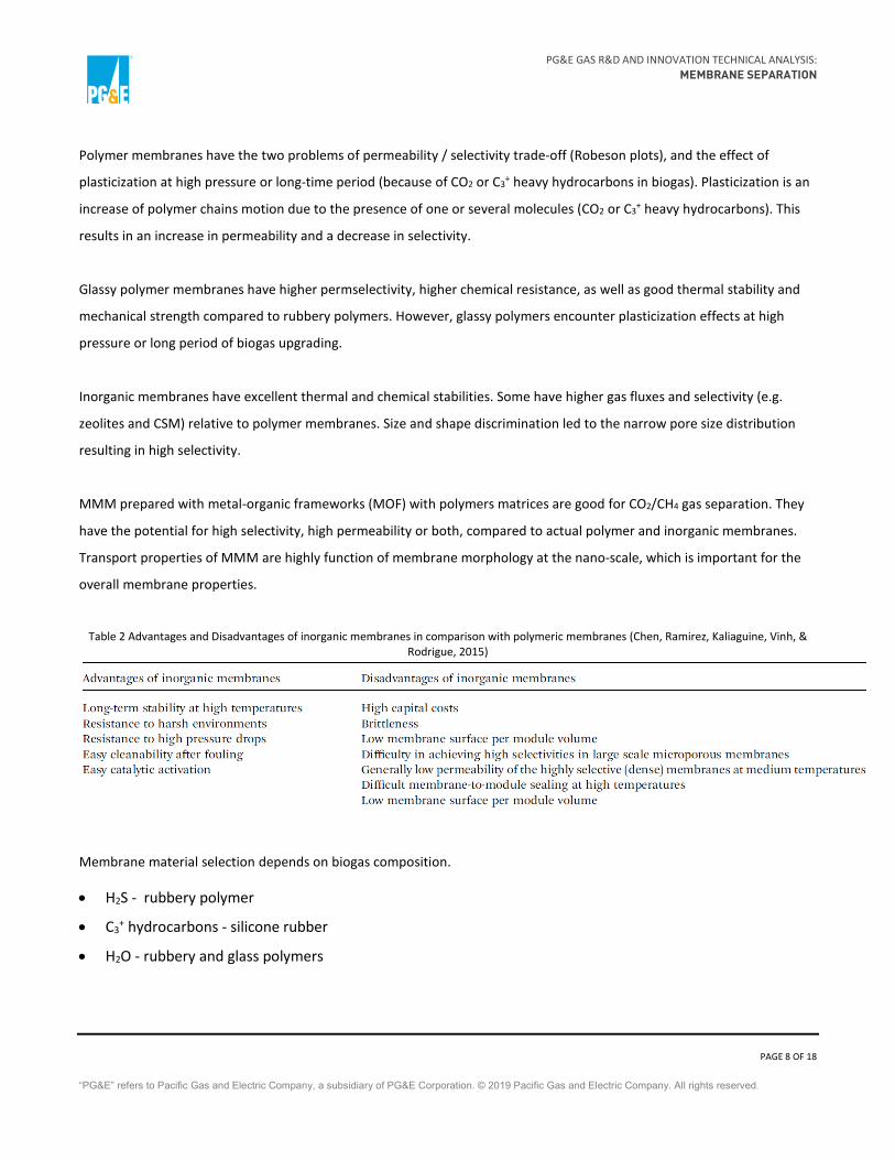
Table 2 Advantages and Disadvantages of inorganic membranes in comparison with polymeric membranes (Chen, Ramirez, Kaliaguine, Vinh, & Rodrigue, 2015)
Membrane material selection depends on biogas composition.
• H2S - rubbery polymer
• C3+ hydrocarbons - silicone rubber
• H2O - rubbery and glass polymers

PG&E GAS R&D AND INNOVATION TECHNICAL ANALYSIS: MEMBRANE SEPARATION
PAGE 9 OF 18
“PG&E” refers to Pacific Gas and Electric Company, a subsidiary of PG&E Corporation. © 2019 Pacific Gas and Electric Company. All rights reserved.
• CO2 – polyimides
o Matrimid®, Kapton®, P84 are inexpensive with low permeabilities
o 6FDA-based polyimides are expensive with better performance
1.3 MODULE TYPE Three common types of configurations (Chen, Ramirez, Kaliaguine, Vinh, & Rodrigue, 2015):
• Hollow fiber module
• Spiral wound module
• Envelope (aka plate and frame) module
Hollow fiber (Air Liquide, 2018) Spiral wound (Bradford, 2015) Envelope (Bradford, 2015)
Table 3 Comparison of hollow fiber, spiral wound, and envelope (Chen, Ramirez, Kaliaguine, Vinh, & Rodrigue, 2015)
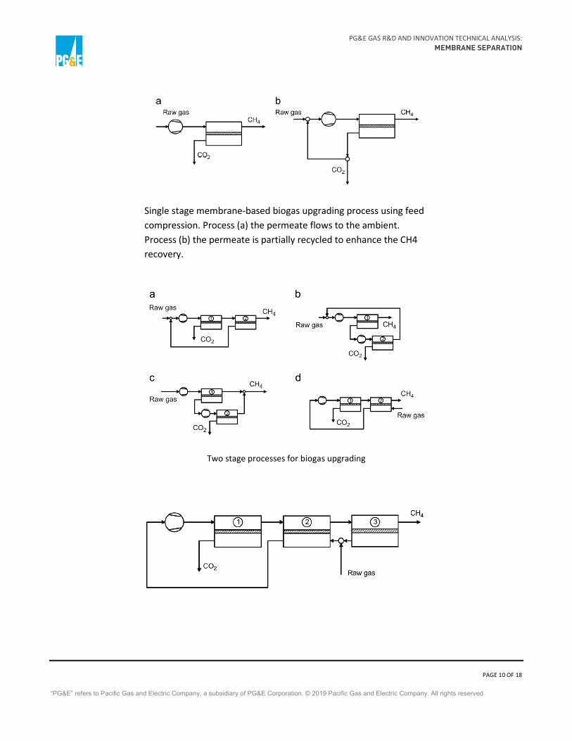
1.4 DESIGN OF MEMBRANE SYSTEMS FOR BIOGAS UPGRADING Below are illustrations of various configurations for membrane only upgrading (Chen, Ramirez, Kaliaguine, Vinh, & Rodrigue, 2015)
PG&E GAS R&D AND INNOVATION TECHNICAL ANALYSIS: MEMBRANE SEPARATION
PAGE 10 OF 18
“PG&E” refers to Pacific Gas and Electric Company, a subsidiary of PG&E Corporation. © 2019 Pacific Gas and Electric Company. All rights reserved.
Single stage membrane-based biogas upgrading process using feed compression. Process (a) the permeate flows to the ambient. Process (b) the permeate is partially recycled to enhance the CH4 recovery.
Two stage processes for biogas upgrading
PG&E GAS R&D AND INNOVATION TECHNICAL ANALYSIS: MEMBRANE SEPARATION
PAGE 11 OF 18
“PG&E” refers to Pacific Gas and Electric Company, a subsidiary of PG&E Corporation. © 2019 Pacific Gas and Electric Company. All rights reserved.
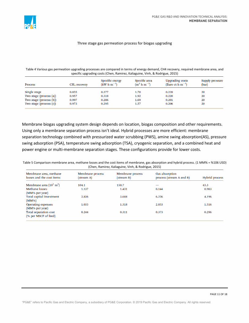
Three stage gas permeation process for biogas upgrading
Table 4 Various gas permeation upgrading processes are compared in terms of energy demand, CH4 recovery, required membrane area, and specific upgrading costs (Chen, Ramirez, Kaliaguine, Vinh, & Rodrigue, 2015)
Membrane biogas upgrading system design depends on location, biogas composition and other requirements. Using only a membrane separation process isn’t ideal. Hybrid processes are more efficient: membrane separation technology combined with pressurized water scrubbing (PWS), amine swing absorption(AS), pressure swing adsorption (PSA), temperature swing adsorption (TSA), cryogenic separation, and a combined heat and power engine or multi-membrane separation stages. These configurations provide for lower costs.
Table 5 Comparison membrane area, methane losses and the cost items of membrane, gas absorption and hybrid process. (1 MM% = %106 USD) (Chen, Ramirez, Kaliaguine, Vinh, & Rodrigue, 2015)

PG&E GAS R&D AND INNOVATION TECHNICAL ANALYSIS: MEMBRANE SEPARATION
PAGE 12 OF 18
“PG&E” refers to Pacific Gas and Electric Company, a subsidiary of PG&E Corporation. © 2019 Pacific Gas and Electric Company. All rights reserved.
Table 6 Comparison and evaluation of the costs of different biogas upgrading technologies (Chen, Ramirez, Kaliaguine, Vinh, & Rodrigue, 2015)
2 Membrane Separation Technologies A comparison of commercial membrane suppliers is provided in the two tables below.
Table 7 Principal membrane suppliers for natural gas separation systems (Chen, Ramirez, Kaliaguine, Vinh, & Rodrigue, 2015)
Table 8 Current commercial membrane materials and selectivities for separation of impurities from natural gas (Chen, Ramirez, Kaliaguine, Vinh,
& Rodrigue, 2015)

PG&E GAS R&D AND INNOVATION TECHNICAL ANALYSIS: MEMBRANE SEPARATION
PAGE 13 OF 18
“PG&E” refers to Pacific Gas and Electric Company, a subsidiary of PG&E Corporation. © 2019 Pacific Gas and Electric Company. All rights reserved.

PG&E GAS R&D AND INNOVATION TECHNICAL ANALYSIS: MEMBRANE SEPARATION
PAGE 14 OF 18
“PG&E” refers to Pacific Gas and Electric Company, a subsidiary of PG&E Corporation. © 2019 Pacific Gas and Electric Company. All rights reserved.
2.1 ADDITIONAL INFORMATION - PUBLICLY AVAILABLE BY VENDOR
Air Products PRISM® (Air Products, 2016)

PG&E GAS R&D AND INNOVATION TECHNICAL ANALYSIS: MEMBRANE SEPARATION
PAGE 15 OF 18
“PG&E” refers to Pacific Gas and Electric Company, a subsidiary of PG&E Corporation. © 2019 Pacific Gas and Electric Company. All rights reserved.
Bright Biomethane (Bright Biomethane, 2018)
• 99.5% methane recovery
• 0.22 kWh/Nm3 biogas electricity consumption
• No heat required for the biogas upgrading process
• Heat recovery > 0.25 kWt/Nm3 biogas covering the main energy consumption of the biogas facility.
A Bright Biomethane CO2 recovery unit can also be integrated with the standard 3 or 2 stage membrane upgrading systems. The high separation efficiency of the membranes means that the energy consumption of CO2 liquification is much lower than conventional systems. No water or chemicals are needed in the Bright Biomethane process which means that there are no disposal problems, such as acid water or chemicals that can be an unforeseen cost with other technologies Our systems are available from 40 Nm3/hr to 5,000 Nm3/hr (and higher).

PG&E GAS R&D AND INNOVATION TECHNICAL ANALYSIS: MEMBRANE SEPARATION
PAGE 16 OF 18
“PG&E” refers to Pacific Gas and Electric Company, a subsidiary of PG&E Corporation. © 2019 Pacific Gas and Electric Company. All rights reserved.
Prodeval VALOPUR® (Prodeval Gas Process Engineering)
The process is based on the use of SEPURAN® highly efficient membranes (produced by EVONIK Company) that
allows for a CH4 recovery > 99 %. After the biogas is pretreated, it is compressed between 10 and 16 barg,
before entry into the membrane filtration modules.

PG&E GAS R&D AND INNOVATION TECHNICAL ANALYSIS: MEMBRANE SEPARATION
PAGE 17 OF 18
“PG&E” refers to Pacific Gas and Electric Company, a subsidiary of PG&E Corporation. © 2019 Pacific Gas and Electric Company. All rights reserved.
3 R&D Opportunities (Chen, Ramirez, Kaliaguine, Vinh, & Rodrigue, 2015)
• Determine new materials with separation factor > 60, adequate permeance, suppression of plasticization at
high CO2 partial pressures, and enhanced long term stability of gas permeation systems
• Membrane-based biogas upgrading systems should simultaneously separate CO2/CH4 and H2S/CH4 with
membranes based on different types of materials
• Improve ease of operation and energy efficiency of membrane-based biogas upgrading systems

PG&E GAS R&D AND INNOVATION TECHNICAL ANALYSIS: MEMBRANE SEPARATION
PAGE 18 OF 18
“PG&E” refers to Pacific Gas and Electric Company, a subsidiary of PG&E Corporation. © 2019 Pacific Gas and Electric Company. All rights reserved.
References Air Liquide. (2018). Biogas Natural Energy Solutions. Retrieved from Air Liquide:
https://www.airliquideadvancedseparations.com/sites/medal/files/2018/05/01/biogas_customer.pdf
Air Products. (2016). PRISM® Membrane Separators. Retrieved from Air Products: https://membraneinsider.com/wp-content/uploads/2016/07/pb_biogas_brochure.pdf
Bradford, L. (2015). Membrane Separation. Retrieved from SlidePlayer: http://slideplayer.com/slide/4427966/
Bright Biomethane. (2018). Membrane Biogas Upgrading Systems. Retrieved from Bright Biomethane: https://www.brightbiomethane.com/wp-content/uploads/sites/2/2018/04/Bright-Biomethane-Brochure-EN-A-Bright-Idea-for-the-Perfect-Biogas-Plant-Solution.pdf
Chen, X. Y., Ramirez, A. A., Kaliaguine, S., Vinh, H. d., & Rodrigue, D. (2015, February). Membrane gas separation technologies for biogas upgrading. RSC Advances, 5(31). Retrieved from https://www.researchgate.net/publication/272423302_Membrane_gas_separation_technologies_for_biogas_upgrading
Prodeval Gas Process Engineering. (n.d.). Valopur Biogas Upgrading Unit - Membrane Technology. Retrieved from Prodeval: https://www.prodeval.eu/files/Telechargement/English/Fiche%20produit%20PRODEVAL_Valopur_EN.pdf
Xia, Y. (2018, January). Microporous Polymer Membranes for Gas Separation. Palo Alto, CA, USA: Stanford University.