mem 201 – week 3 - drexel university information technologyrcc34/files/teaching/mem201 l3... ·...
TRANSCRIPT

2008/10/16Dept of Mechanical Engineering and Mechanics, Drexel University
Fundamentals of Computer Aided Design
• Introduction to Sketching – Isometric, Oblique, Perspective
• Orthographic Views
MEM 201 – Week 3

2008/10/16
Introduction to Sketching• Used to portray 3D shapes onto 2D paper.
• 3D axes appear differently when shown on a piece of paper
• Mainly Three Types:– Isometric– Oblique– Perspective
2008/10/16
Coordinate Systems
• Consists of three mutually perpendicular lines that meet at a single point in 3D space.
• Two Types– Positive Coordinate system (Right Handed) – Mostly
used– Negative Coordinate system (Left Handed)
• Classifications – Cartesian– Spherical– Cylindrical
2008/10/16
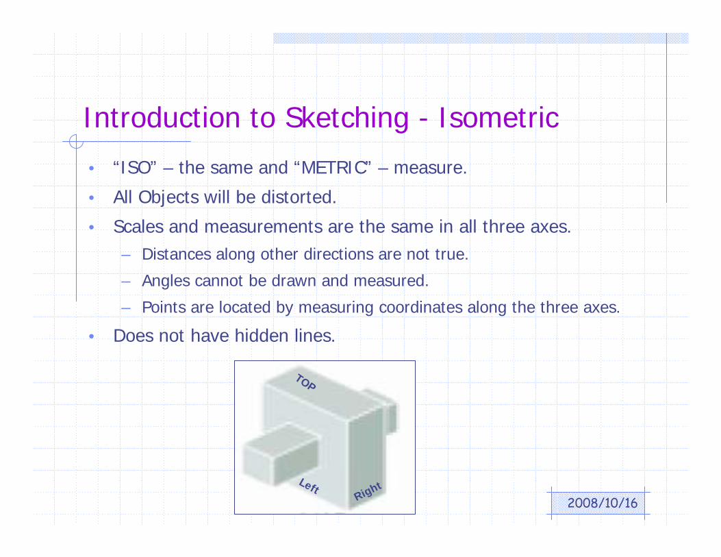
Introduction to Sketching - Isometric
• “ISO” – the same and “METRIC” – measure.
• All Objects will be distorted.
• Scales and measurements are the same in all three axes.– Distances along other directions are not true.
– Angles cannot be drawn and measured.
– Points are located by measuring coordinates along the three axes.
• Does not have hidden lines.
TOP
RightLeft
2008/10/16
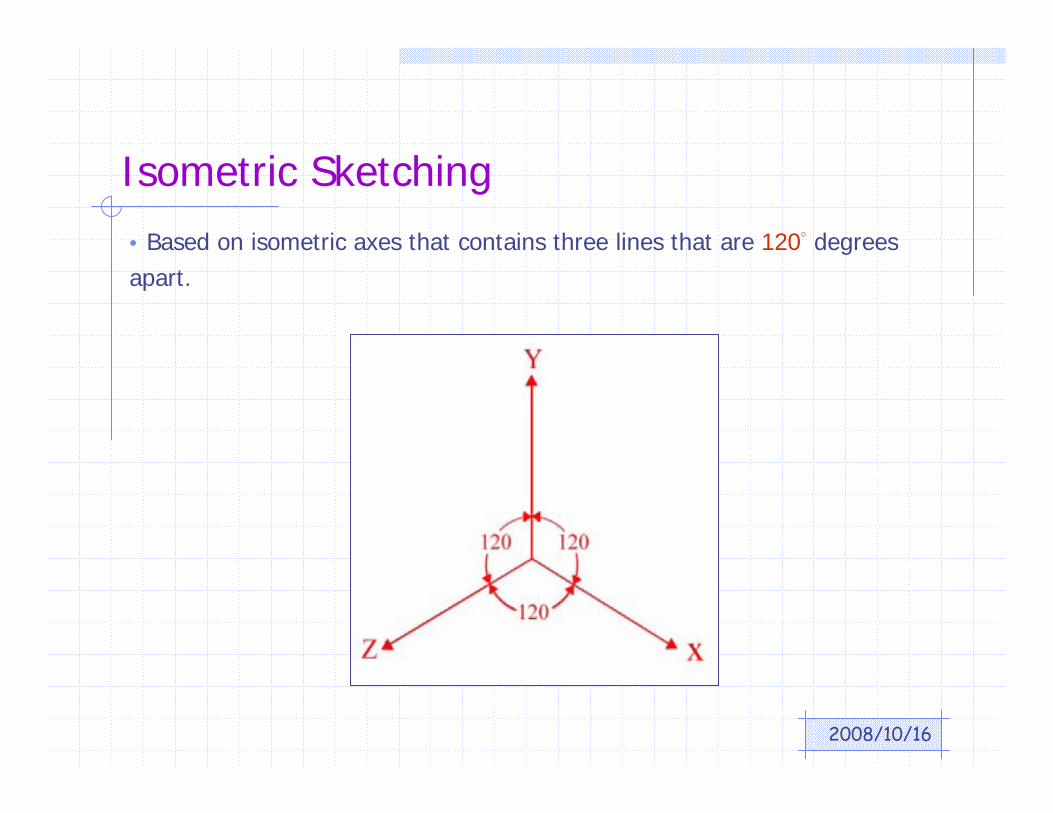
Isometric Sketching• Based on isometric axes that contains three lines that are 120° degrees apart.
2008/10/16
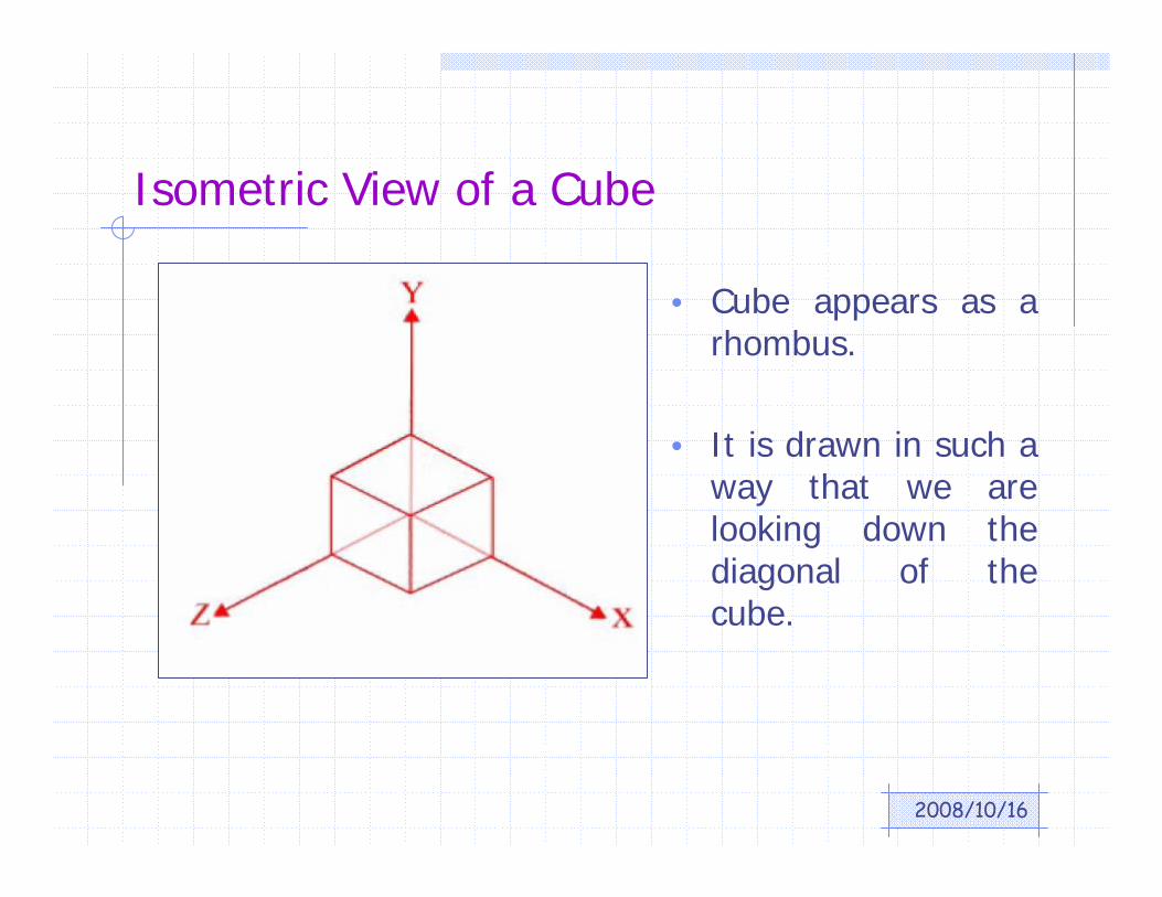
Isometric View of a Cube
• Cube appears as a rhombus.
• It is drawn in such a way that we are looking down the diagonal of the cube.
2008/10/16
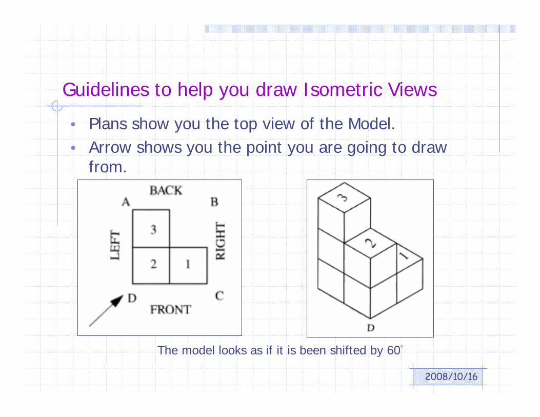
Guidelines to help you draw Isometric Views
• Plans show you the top view of the Model.• Arrow shows you the point you are going to draw
from.
The model looks as if it is been shifted by 60°

2008/10/16
Steps to Follow
PLAN Front
• Identify Corner “C” and use it as a starting point.
• Move either to the left or right to represent the edge and then complete its surface.
• Move to the opposite direction and complete the surface with corner “C” as the common vertex.
• Continue drawing the surface using the dots as an aid.

2008/10/16
Introduction to Sketching - Oblique
• Contains one set of perpendicular axis lines and one receding lines.
• Frontal project plane is rectangular and all measurements in it are true.
• Receding line distances may or may not be true.
2008/10/16
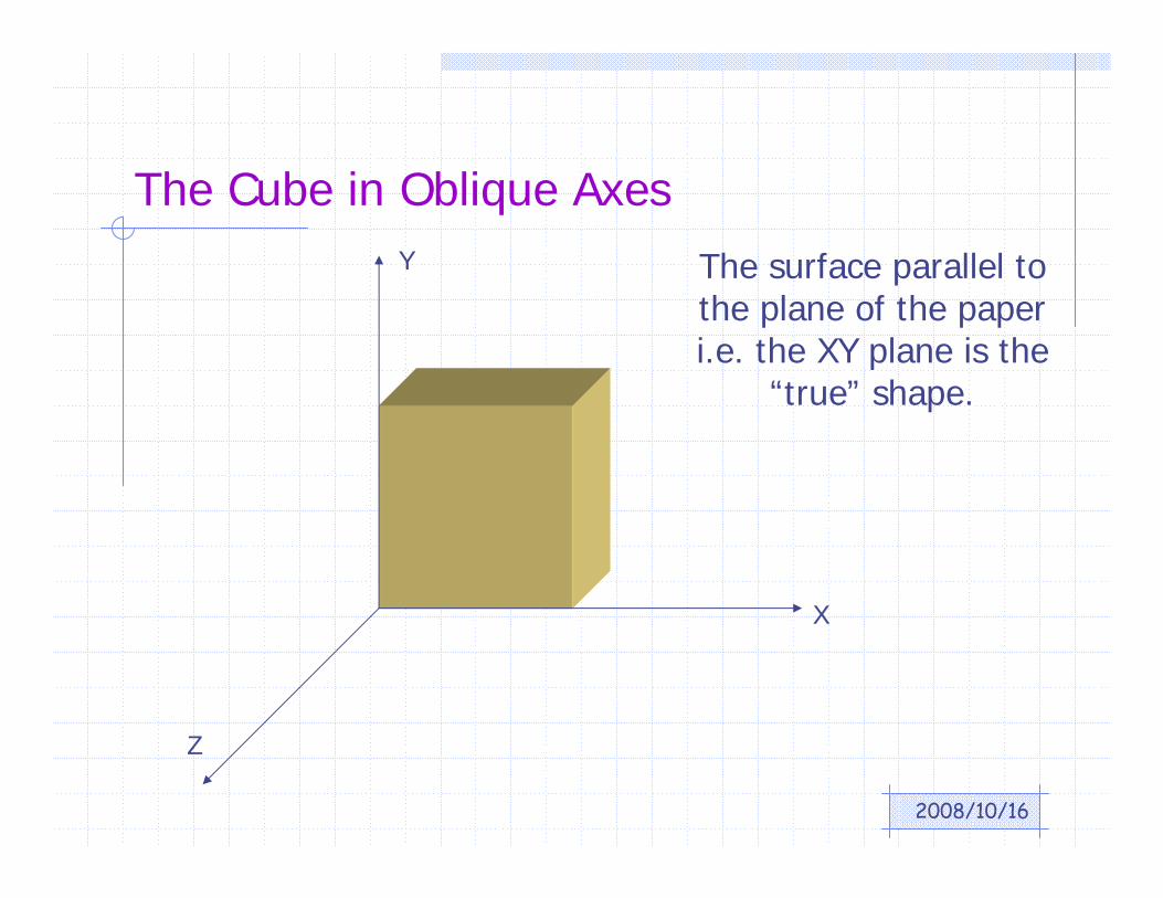
The Cube in Oblique Axes
X
Y
Z
The surface parallel to the plane of the paper i.e. the XY plane is the
“true” shape.
2008/10/16
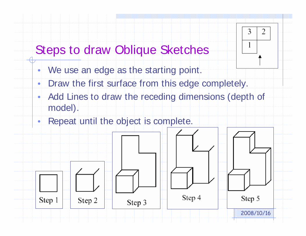
Steps to draw Oblique Sketches
• We use an edge as the starting point.• Draw the first surface from this edge completely.• Add Lines to draw the receding dimensions (depth of
model).• Repeat until the object is complete.
2008/10/16
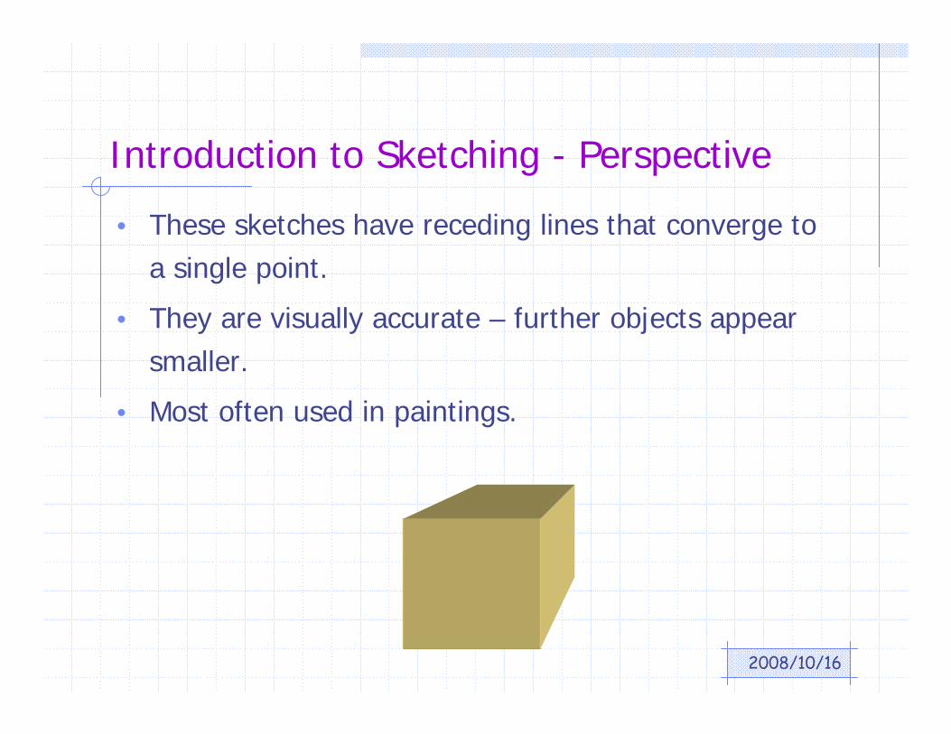
Introduction to Sketching - Perspective
• These sketches have receding lines that converge to a single point.
• They are visually accurate – further objects appear smaller.
• Most often used in paintings.
2008/10/16
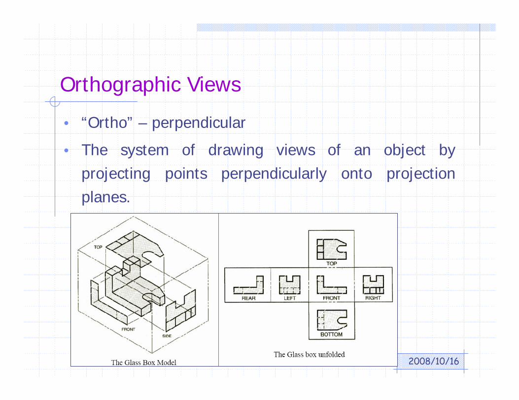
Orthographic Views
• “Ortho” – perpendicular
• The system of drawing views of an object by projecting points perpendicularly onto projection planes.
2008/10/16
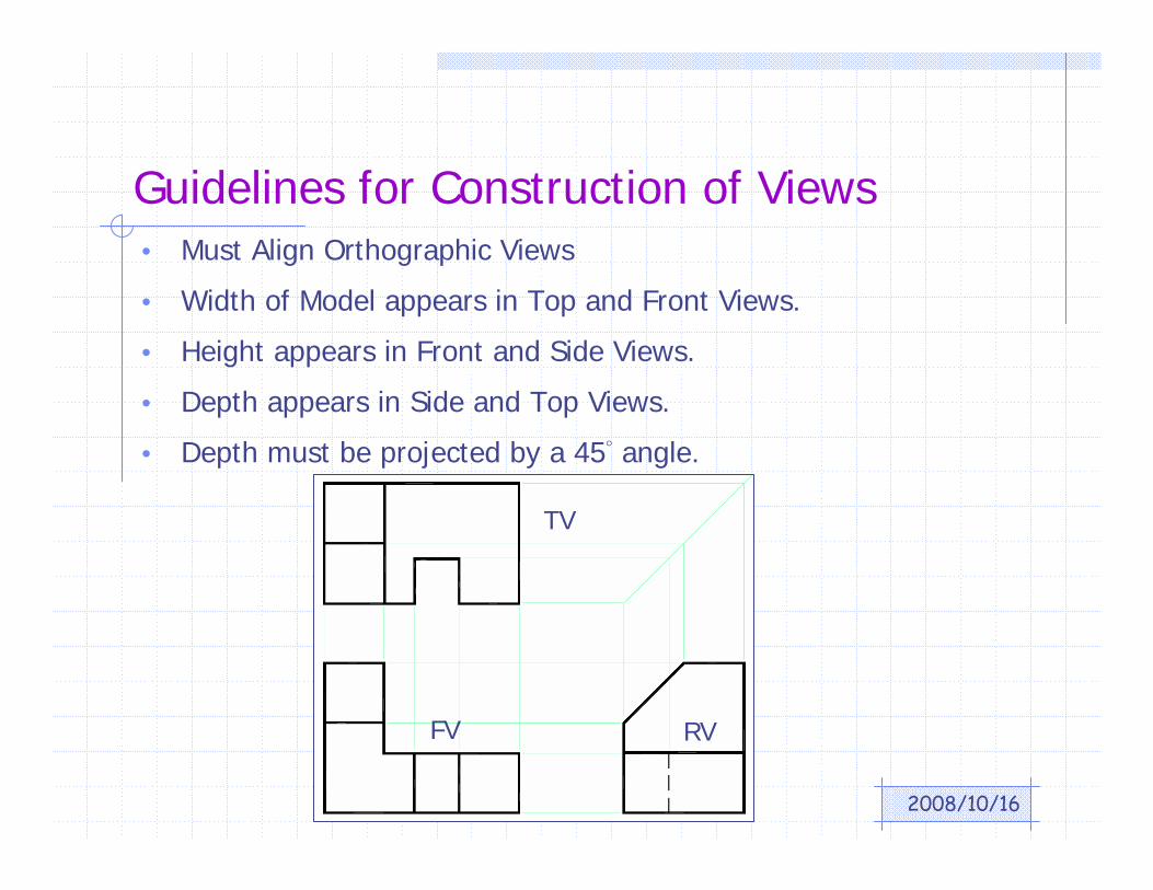
• Must Align Orthographic Views
• Width of Model appears in Top and Front Views.
• Height appears in Front and Side Views.
• Depth appears in Side and Top Views.
• Depth must be projected by a 45° angle.
Guidelines for Construction of Views
FV RV
TV
2008/10/16
Guidelines for selecting a Front View (FV)
• Represents the most natural position of use.
• Provides the best shape description or most characteristic contours.
• Has longest dimension.
• Has fewest hidden features.

2008/10/16
Do not draw these…….

2008/10/16
Types of Lines & Precedence
• Object lines (visible lines) – solid lines – represent visible surfaces or edges of the object.
• Hidden lines – dashed lines – invisible edges of the object.
• Centerlines – long-short dashes – used to show centers of circles and arcs.

2008/10/16
Line Precedence• When one type of line falls in line with a different line type, draw
the line that is most important based on precedence:
– Object lines take precedence over hidden lines and centerlines.
– Hidden lines take precedence over centerlines.
– In sectioning, cutting plane lines take precedence over center lines.
2008/10/16
Orthographic Projections in AutoCAD
• Group entities together into LAYERS.
– Layers can be turned on and off as needed to display only needed info. (Example: Architectural drawing – layers for walls, windows plumbing, dimensions, electrical, etc.)
– Different professional organizations have adopted different layering standards.
• Use the layer manager to create layers with appropriate line type and color.
– object lines – hidden lines – section lines and hatching – text and dimensions – title border
2008/10/16
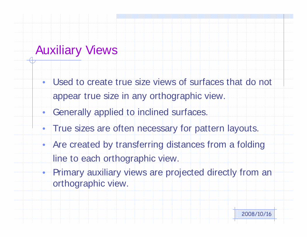
Auxiliary Views
• Used to create true size views of surfaces that do not appear true size in any orthographic view.
• Generally applied to inclined surfaces.
• True sizes are often necessary for pattern layouts.
• Are created by transferring distances from a folding line to each orthographic view.
• Primary auxiliary views are projected directly from an orthographic view.

2008/10/16
Example

2008/10/16
Auxiliary Drawings• The auxiliary plane is parallel to the inclined surface.
• The auxiliary plane is perpendicular to a principal projection plane (e.g. Frontal) and hinged to it.
• The folding plane is labeled F/1 for the Frontal/1st Auxiliary plane, as an example.
2008/10/16
Questions ?
2008/10/16
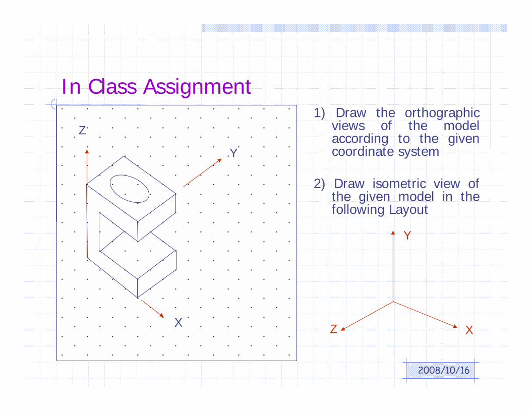
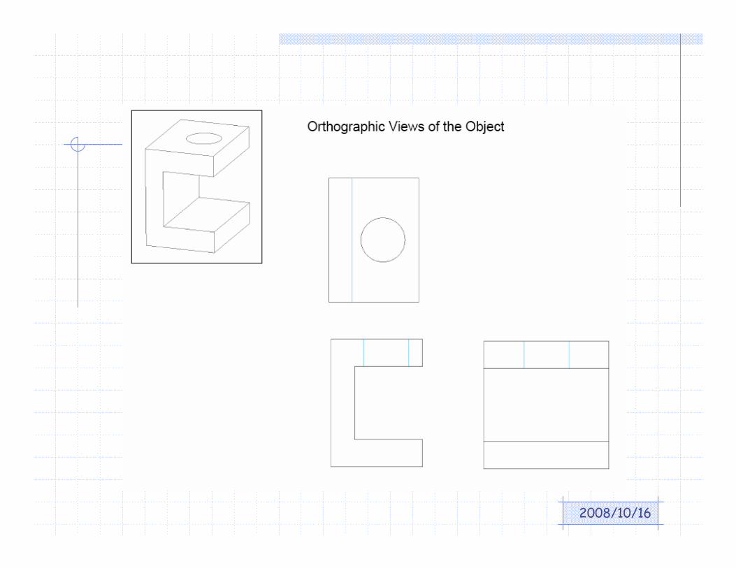
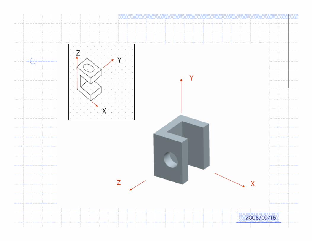
In Class Assignment
X
Y
Z1) Draw the orthographic
views of the model according to the given coordinate system
2) Draw isometric view of the given model in the following Layout
X
Y
Z
2008/10/16
2008/10/16