melting relations in the system feco3–mgco3 and ... · melting relations in the system feco ......
TRANSCRIPT

1 3
Contrib Mineral Petrol (2016) 171:74 DOI 10.1007/s00410-016-1283-3
ORIGINAL PAPER
Melting relations in the system FeCO3–MgCO3 and thermodynamic modelling of Fe–Mg carbonate melts
Nathan Kang1 · Max W. Schmidt1 · Stefano Poli2 · James A. D. Connolly1 · Ettore Franzolin1
Received: 1 August 2015 / Accepted: 29 July 2016 © Springer-Verlag Berlin Heidelberg 2016
Over the pressure range of 3.5–20 GPa, this minimum is 20–35 °C lower than the (metastable) siderite melting tem-perature. By merging all present and previous experimen-tal data, standard state (298.15 K, 1 bar) thermodynamic properties of the magnesite melt (MgCO3L) end member are calculated and the properties of (Fe,Mg)CO3 melt fit by a regular solution model with an interaction parameter of −7600 J/mol. The solution model reproduces the asym-metric melting loop and predicts the thermal minimum at 1240 °C near the siderite side at XMg = 0.2 (3.5 GPa). The solution model is applicable to pressures reaching to the bottom of the upper mantle and allows calculation of phase relations in the FeO–MgO–O2–C system.
Keywords Siderite · Magnesite · Experimental petrology · Melting relations · Oxidation · Solution model
Introduction
The stability of carbonates against decarbonation and melting is of considerable interest for understanding the global carbon cycle (Dasgupta and Hirschmann 2010). Carbon solubilities in mantle silicates are low, typically a few ppm and at most 10–20 ppm (Keppler et al. 2003; Shcheka et al. 2006; Panero and Kabbes 2008). Hence, carbon is likely to be stored in a separate phase either oxi-dized as carbonate(s), carbonated fluids (as documented, for example, in inclusions in diamonds; Wang et al. 1996; Stachel et al. 2000; Klein-BenDavid et al. 2009) or melts or in reduced phases such as diamonds, carbides or Fe–C alloys (Boulard et al. 2012). Computed phase equilibria on sediment bulk compositions and metabasalts as well as phase equilibria experiments on carbonated sediments, basaltic eclogites and peridotites suggest that Ca–Mg–Fe
Abstract To constrain the thermodynamics and melt-ing relations of the siderite–magnesite (FeCO3–MgCO3) system, 27 piston cylinder experiments were conducted at 3.5 GPa and 1170–1575 °C. Fe-rich compositions were also investigated with 13 multi-anvil experiments at 10, 13.6 and 20 GPa, 1500–1890 °C. At 3.5 GPa, the solid solution siderite–magnesite coexists with melt over a com-positional range of XMg (=Mg/(Mg + Fetot)) = 0.38–1.0, while at ≥10 GPa solid solution appears to be complete. At 3.5 GPa, the system is pseudo-binary because of the lim-ited stability of siderite or liquid FeCO3, Fe-rich carbon-ates decomposing at subsolidus conditions to magnetite–magnesioferrite solid solution, graphite and CO2. Similar reactions also occur with liquid FeCO3 resulting in melt species with ferric iron components, but the decomposi-tion of the liquid decreases in importance with pressure. At 3.5 GPa, the metastable melting temperature of pure sider-ite is located at 1264 °C, whereas pure magnesite melts at 1629 °C. The melting loop is non-ideal on the Fe side where the dissociation reaction resulting in Fe3+ in the melt depresses melting temperatures and causes a minimum.
Communicated by Chris Ballhaus.
Electronic supplementary material The online version of this article (doi:10.1007/s00410-016-1283-3) contains supplementary material, which is available to authorized users.
* Nathan Kang [email protected]
1 Department of Earth Sciences, Institute of Geochemistry and Petrology, ETH, Clausiusstrasse 25, 8092 Zurich, Switzerland
2 Dipartimento di Scienze della Terra, Università degli Studi di Milano, Via Botticelli 23, 20133 Milan, Italy

Contrib Mineral Petrol (2016) 171:74
1 3
74 Page 2 of 16
carbonates remain stable beyond arc depths and enter the deeper parts of the mantle with higher melting tempera-tures than typical modern subduction geotherms (Wallace and Green 1988; Falloon and Green 1989; Yaxley and Green 1994; Molina and Poli 2000; Kerrick and Connolly 2001a, b; Dasgupta et al. 2004; Yaxley and Brey 2004; Dasgupta and Hirschmann 2006; Poli et al. 2009; Mann and Schmidt 2015). At depth greater than 4–5 GPa, experi-ments indicate that magnesite (MgCO3) is the most stable carbonate (Biellmann et al. 1993; Fiquet et al. 2002; Isshiki et al. 2004). In general, carbonates tend to have high XMg values compared to coexisting Fe–Mg silicates; typical compositional ranges for peridotites are XMg
magnesite−siderite of 0.93–0.99 (Brey et al. 2008, 2009; Ghosh et al. 2009), for metabasalts 0.67–0.82 (Dasgupta et al. 2004; Yaxley and Brey 2004; Dasgupta et al. 2005), for metapelites 0.3–0.8 (Thomsen and Schmidt 2008; Grassi and Schmidt 2011) and 0.2–0.9 in carbonatites (Buckley and Woolley 1990). Hence, there is ample reason to investigate the Fe-rich side of the magnesite–siderite binary experimentally and to develop a thermodynamic model for the solid and liquid solutions in this system.
At the extreme Fe-rich end, natural siderite is gener-ally associated with ankerite CaFe(CO3)2 in sedimentary banded iron formations (BIFs; Klein 2005; Kholodov and Butuzova 2008). Before the rise of oxygen ~2.3 Ga ago, BIFs and anoxic shales were not only platform sedi-ments but also abundant on deep ocean floors (Beukes and Gutzmer 2008), but most of the deep deposits have disappeared from the Earth surface via subduction (Polat et al. 2002; Dobson and Brodholt 2005). High-pressure devolatilization and melting in such Fe-rich systems are poorly understood, and experimental investigation of the MgCO3–FeCO3 system is required to understand the fate of subducted C-bearing BIFs. Siderite also occurs in hydro-thermal veins, in extraterrestrial materials such as on Mars (Morris et al. 2010), in the Martian meteorite ALH84001 (Eiler et al. 2002) and in altered igneous rocks.
The melting reaction of pure siderite becomes stable above 6.8 GPa (Tao et al. 2013; Kang et al. 2015) and the melting of pure magnesite above 2.5 GPa (Irving and Wyl-lie 1975). At lower pressures, magnesite decomposes to MgO + CO2, while siderite decomposition occurs through a redox reaction to magnetite and graphite. Due to the dis-cordance of the graphite–CO2 (CCO) oxygen buffer with the common Fe buffers (iron–wustite, wustite–magnetite and magnetite–haematite), wustite + CO2 only become sta-ble at temperatures higher than siderite stability (Fig. 1).
Experimental studies on the subsolidus phase relations in the MgCO3–FeCO3 system at 0.2–0.4 GPa, 350–550 °C (Rosenberg 1967), at 1.5 GPa, 600–800 °C (Goldsmith et al. 1962), and at 3.5 GPa, 900–1100 °C (Franzolin et al. 2011) prove that there is continuous solid solution
between siderite and magnesite. Subsolidus phase relations were then thermodynamically modelled within the ternary Ca–Mg–Fe carbonate system at high pressures (Davidson 1994; Franzolin et al. 2011; Holland and Powell 2011). The binary MgCO3–FeCO3 has recently been studied at 6 GPa and 900–1700 °C (Shatskiy et al. 2015a), where results suggest minor incongruent melting of Mg–Fe carbonate to form oxide–carbonate liquids coexisting with CO2 fluid. Phase equilibria studies in particular on compositions near Fe end members are complicated by the fact that at con-ditions above the iron–wustite buffer, some of the ferrous iron always oxidizes to ferric iron.
This study defines the melting loop of the MgCO3–FeCO3 binary at 3.5 GPa, 1170–1575 °C, filling a decisive gap on the melting behaviour of iron-bearing carbonates at mantle conditions. In addition, we present experimen-tal data constraining the Fe-rich side of this binary at 10, 13.6 and 20 GPa. Based on the experimental data, we fit the thermodynamic solution model for Mg–Fe carbonate melts considering the influence of fO2 and redox reactions of iron-bearing phases. This melt model provides the first approximation for the prediction of Mg–Fe carbonate melt-ing relations at pressure.
Experimental and analytical methods
Starting materials
Starting materials were prepared from natural magne-site with an XMg of 0.989 from Obersdorf (Philipp 1998), synthetic magnesite (99.9 % MgCO3 powder from Alfa-Aesar) and synthetic siderite. Starting materials for piston cylinder experiments were mixtures of natural magnesite and synthetic siderite, while synthetic magnesite was used in the multi-anvil experiments. Magnesite was dried at 220 °C for ~16 h and then stored at 110 °C. Siderite was synthesized from iron oxalate, sealed into gold capsules of 5.4 mm outer diameter, at 350 °C and 200 MPa in an externally heated cold seal vessel run for 6 days (French 1971). The synthetic siderite had a grey-white, slightly brownish colour. Each newly synthesized siderite batch was analysed by scanning electron microscope and X-ray diffraction, which did yield pure siderite. Siderite was stored at ambient temperature in an evacuated glass des-iccator to slow oxidation, but with time develops a more intensive brown colour due to oxidation. Storing sider-ite at, for example, 110 °C in a vacuum oven to prevent hydration led to more rapid oxidation. Drying siderite is not suitable as it starts to oxidize at 110 °C; hence, our starting materials may have contained small amounts of moisture. To minimize absorbed H2O and oxidation, sider-ite was synthesized repeatedly as required and experiments

Contrib Mineral Petrol (2016) 171:74
1 3
Page 3 of 16 74
were done in less than 2 months after synthesis. Magnesite and siderite were mixed under alcohol, and after drying, the starting mixtures (Table 1) were stored in a glass dessi-cator under vacuum.
Experimental methods
High-pressure experiments were conducted in an end-loaded piston cylinder at 3.5 GPa and in a 1000 ton Walker-type multi-anvil at 10, 13.6 and 20 GPa. Piston cylinder experiments were run with Teflon foil–talc–Pyrex–graph-ite–MgO assemblies. To avoid Fe loss to metal capsules and prevent the consequent oxidation of the sample, inner graphite capsules were inserted into 3-mm OD Pt capsules, which were welded shut. Run temperatures were controlled by Eurotherm controllers within ± 2 °C, using B-type (Pt94Rh6/Pt70Rh30) thermocouples. The assembly was grad-ually decompressed after quenching the experiments by turning off the heating power.
Multi-anvil experiments were performed employing tungsten carbide cubes with truncation edge lengths of 11, 8 and 3.5 mm in combination with prefabricated Cr2O3-doped MgO octahedra of 18, 14 and 10 mm edge length (18/11 assembly for 10 GPa, 14/8 for 13.6 GPa and 10/3.5 for 20 GPa). Assemblies were composed of stepped (18/11, 14/8) or straight (10/3.5) LaCrO3 heaters, ZrO2 sleeves, internal MgO spacers and an molybdenum end ring and disc. The starting materials were loaded directly into Au80Pd20 capsules stacked in the central part of the furnace assembly. The 18/11 and 14/8 assemblies contained axial thermocouples, while the 10/3.5 assembly has a thermo-couple running across the centre of the furnace (Stewart et al. 2006). Temperature was controlled using a B-type (Pt94Rh6/Pt70Rh30) thermocouple for 10 and 13.6 GPa or C type (W95Re5–W74Re26) for 20 GPa. Typical ther-mal gradients across a capsule are 15–25 °C in 18/11 and 14/8 assemblies. Temperature gradients within the 10/3.5 assembly are 30–50 °C over the capsule length of 1.2 mm.
Temperature (°C)
Pre
ssur
e (G
Pa)
Sid
Sid
Mt +
Gph
+ C
O 2
c = 3 (Fe-C-O2)at CCO buffer
(Mt, Gph, CO2)
Liq
+ C
O2 +
C
Mt + G
ph
[Sid]
OOeF 2
C
Wu
Mt Hem
Sid, Liq
CO2
Gph
Fe2(CO3)3III
Liq’
~6.8
(Liq)
~350
(Liq)
~1020 ~1430
[Wu] Liq
Wu +
CO 2
Mt + Gph + CO2
(Mt, Gph)
Liq + Gph
Wu + CO2
ba
Mag
MgO + CO2
c = 2 (MgO-CO2)
(MgCO3L)
~2.6
~1550 °C
MgC
O3L
Mag
MgCO3L
MgO + CO2
(MgO
, CO
2)(Mag)
MgO O2
C
MagCO2
MgCO3L
IW
log(fO
2)
Temperature (°C)
HM
CCO
MW
6.8 GPa
Fig. 1 Schreinemaker analysis of the melting relations of siderite and magnesite at their lowest melting pressures. The MgO–CO2 system (a) behaves as a true binary and has a simple topology, but phase rela-tions describing siderite melting require three system components (FeO–C–O2), opening up a magnetite + graphite field (b). Wustite only becomes stable at higher temperatures than siderite stability, a consequence of the discordance between the CCO buffer and the Fe–O buffers (see insert). The topology of the FO–C–CO2 system is drawn for two options: in black and blue reactions for a siderite melt with stoichiometric siderite composition, and in black and red for siderite melt with a minor ferric component and dissolved CO2.
Approximate pressures and/or temperatures are indicated, for mag-nesite as determined by Irvine and Wyllie (1975) and for siderite as determined by Tao et al. (2013) and Kang et al. (2015). Phase abbre-viations in text, figures and tables are: Wu wustite; Carbss siderite–magnesite solid solution; Mtss magnetite–magnesioferrite solid solu-tion; Gph graphite; Liq carbonate melt (containing Fe oxide quench phases); Mwuss wustite–periclase solid solution; Magrem magnesite remnant stemming from starting material; Carb-q carbonate quench; Mt-q magnetite quench; MgCO3L magnesite liquid; FeCO3L siderite liquid; Sid siderite; Mag magnesite; Mt magnetite; Per periclase
Contrib Mineral Petrol (2016) 171:74
1 3
74 Page 4 of 16
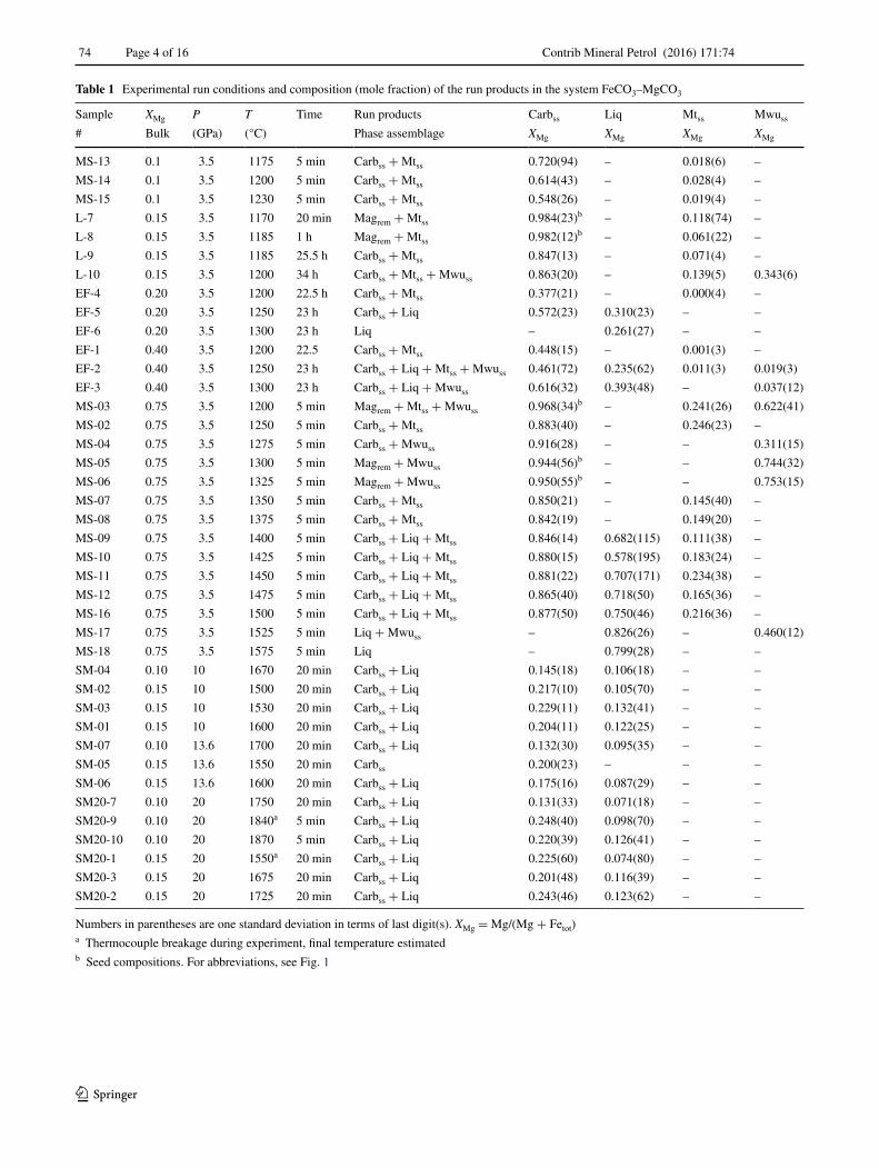
Table 1 Experimental run conditions and composition (mole fraction) of the run products in the system FeCO3–MgCO3
Numbers in parentheses are one standard deviation in terms of last digit(s). XMg = Mg/(Mg + Fetot)a Thermocouple breakage during experiment, final temperature estimatedb Seed compositions. For abbreviations, see Fig. 1
Sample XMg P T Time Run products Carbss Liq Mtss Mwuss
# Bulk (GPa) (°C) Phase assemblage XMg XMg XMg XMg
MS-13 0.1 3.5 1175 5 min Carbss + Mtss 0.720(94) – 0.018(6) –
MS-14 0.1 3.5 1200 5 min Carbss + Mtss 0.614(43) – 0.028(4) –
MS-15 0.1 3.5 1230 5 min Carbss + Mtss 0.548(26) – 0.019(4) –
L-7 0.15 3.5 1170 20 min Magrem + Mtss 0.984(23)b – 0.118(74) –
L-8 0.15 3.5 1185 1 h Magrem + Mtss 0.982(12)b – 0.061(22) –
L-9 0.15 3.5 1185 25.5 h Carbss + Mtss 0.847(13) – 0.071(4) –
L-10 0.15 3.5 1200 34 h Carbss + Mtss + Mwuss 0.863(20) – 0.139(5) 0.343(6)
EF-4 0.20 3.5 1200 22.5 h Carbss + Mtss 0.377(21) – 0.000(4) –
EF-5 0.20 3.5 1250 23 h Carbss + Liq 0.572(23) 0.310(23) – –
EF-6 0.20 3.5 1300 23 h Liq – 0.261(27) – –
EF-1 0.40 3.5 1200 22.5 Carbss + Mtss 0.448(15) – 0.001(3) –
EF-2 0.40 3.5 1250 23 h Carbss + Liq + Mtss + Mwuss 0.461(72) 0.235(62) 0.011(3) 0.019(3)
EF-3 0.40 3.5 1300 23 h Carbss + Liq + Mwuss 0.616(32) 0.393(48) – 0.037(12)
MS-03 0.75 3.5 1200 5 min Magrem + Mtss + Mwuss 0.968(34)b – 0.241(26) 0.622(41)
MS-02 0.75 3.5 1250 5 min Carbss + Mtss 0.883(40) – 0.246(23) –
MS-04 0.75 3.5 1275 5 min Carbss + Mwuss 0.916(28) – – 0.311(15)
MS-05 0.75 3.5 1300 5 min Magrem + Mwuss 0.944(56)b – – 0.744(32)
MS-06 0.75 3.5 1325 5 min Magrem + Mwuss 0.950(55)b – – 0.753(15)
MS-07 0.75 3.5 1350 5 min Carbss + Mtss 0.850(21) – 0.145(40) –
MS-08 0.75 3.5 1375 5 min Carbss + Mtss 0.842(19) – 0.149(20) –
MS-09 0.75 3.5 1400 5 min Carbss + Liq + Mtss 0.846(14) 0.682(115) 0.111(38) –
MS-10 0.75 3.5 1425 5 min Carbss + Liq + Mtss 0.880(15) 0.578(195) 0.183(24) –
MS-11 0.75 3.5 1450 5 min Carbss + Liq + Mtss 0.881(22) 0.707(171) 0.234(38) –
MS-12 0.75 3.5 1475 5 min Carbss + Liq + Mtss 0.865(40) 0.718(50) 0.165(36) –
MS-16 0.75 3.5 1500 5 min Carbss + Liq + Mtss 0.877(50) 0.750(46) 0.216(36) –
MS-17 0.75 3.5 1525 5 min Liq + Mwuss – 0.826(26) – 0.460(12)
MS-18 0.75 3.5 1575 5 min Liq – 0.799(28) – –
SM-04 0.10 10 1670 20 min Carbss + Liq 0.145(18) 0.106(18) – –
SM-02 0.15 10 1500 20 min Carbss + Liq 0.217(10) 0.105(70) – –
SM-03 0.15 10 1530 20 min Carbss + Liq 0.229(11) 0.132(41) – –
SM-01 0.15 10 1600 20 min Carbss + Liq 0.204(11) 0.122(25) – –
SM-07 0.10 13.6 1700 20 min Carbss + Liq 0.132(30) 0.095(35) – –
SM-05 0.15 13.6 1550 20 min Carbss 0.200(23) – – –
SM-06 0.15 13.6 1600 20 min Carbss + Liq 0.175(16) 0.087(29) – –
SM20-7 0.10 20 1750 20 min Carbss + Liq 0.131(33) 0.071(18) – –
SM20-9 0.10 20 1840a 5 min Carbss + Liq 0.248(40) 0.098(70) – –
SM20-10 0.10 20 1870 5 min Carbss + Liq 0.220(39) 0.126(41) – –
SM20-1 0.15 20 1550a 20 min Carbss + Liq 0.225(60) 0.074(80) – –
SM20-3 0.15 20 1675 20 min Carbss + Liq 0.201(48) 0.116(39) – –
SM20-2 0.15 20 1725 20 min Carbss + Liq 0.243(46) 0.123(62) – –

Contrib Mineral Petrol (2016) 171:74
1 3
Page 5 of 16 74
Quenching was done by turning off the heating power and was followed by pressure unloading for about 15–20 h.
Analytical techniques
Capsules were mounted longitudinally in epoxy resin and polished to the centre. The open capsules were repeatedly impregnated in low-viscosity resin to avoid mechanical loss of the exposed phases. Experimental charges were ana-lysed with a JEOL JXA8200 electron microprobe (EPMA) to determine phase compositions. Haematite (Fe2O3) and periclase (MgO) have been used as standards for Fe and Mg. The quenched melt was measured at 15 kV accelera-tion voltage and 6 nA with a beam diameter of 15–20 μm to minimize beam damage. Counting times were 30 s on the peak and 15 s on the background. Note that melt pools with small melt fractions interstitial to grain boundaries were extremely difficult to measure, especially with a defocused electron beam, and contamination by adjacent mineral phases during the measurement could not always be excluded. In such cases, we used an SEM-EDX that allows acquisition using polygonal area measurements. CO2 contents of carbonate melts were estimated by differ-ence of the totals to 100. These estimates were within a few per cent of the expected stoichiometric value with respect to (Mg,Fe2+)CO3. Nevertheless, the quenched melt may contain holes or disperse graphite, thus influencing analyti-cal totals. Secondly, the carbonate melts probably contain a small ferric component, and thirdly, they may dissolve molecular CO2, both leading to CO2 values different from those of (Mg,Fe2+)CO3. Calculated CO2 concentrations were only used to plot liquid compositions in FeO–MgO–CO2 projected from graphite.
High-resolution back-scattered electron (BSE) images were obtained from a Jeol JSM 6390LA scanning electron microscope to study textural relationships between phases. Micro-Raman spectroscopy (Horiba Jobin–Yvon LabRam HR 800) was employed to identify the nature of the oxide phases (spinel group vs magnesiowustite). After analysis, all samples were stored in a desiccator.
Experimental results
Altogether, 40 successful experiments were performed on six different bulk compositions at 3.5, 10, 13.6 and 20 GPa and at temperatures between 1170 and 1890 °C. All experi-mental run conditions, phase assemblages and their molar compositions are presented in Table 1. Distinctive textural features of the experimental charges at subsolidus and melting conditions at 3.5 GPa and at higher pressure are shown in Figs. 2 and 3.
Equilibration and run textures
For the supersolidus experiments, 5–20 min run-time was sufficient to attain textural equilibrium. Enhanced by high temperatures and the presence of a liquid phase, equilib-rium is evidenced by triple junctions, homogenous phase compositions, completely reacted starting materials and pronounced grain growth of subsolidus carbonates. In gen-eral, equilibrium carbonates form discrete large polyhe-dral grains. The onset of partial melting in experiments is detected using textural criteria. Mostly, the liquid migrates and collects in the hotter zone of the capsule. At low melt fractions, interstitial melt pools along grain edges (Fig. 2d) or concentration of melt along capsule walls are observed (Fig. 2b, c). The carbonate melts are not quenchable, and quench phases from the liquid consist of dendritic aggre-gates of carbonates (Carb-q, Fig. 2b, c, d, f) intergrown with iron oxides. Where large enough, these quench oxides have been identified by Raman spectroscopy as magnetite (Mt-q), indicating that the melt contains a minor ferric component.
For the subsolidus experiments, textural and composi-tional equilibrium was more difficult to reach, generally requiring ≥1–2 h run-time. Disequilibrium was indicated by irregular grain shapes Fig. 2a), magnesite-rich mineral cores and compositionally zoned carbonates. The only result that is used from the subsolidus experiments is the carbonate compositions, assuming that the measured car-bonate compositions are (meta)stable at run condition.
Bubbles indicating gas or fluid saturation were rarely observed (Figs. 2, 3), also not in the capsules where con-siderable equilibrium magnetite formed through reac-tion (1). In the subsolidus runs, this may indicate that the copious amounts of CO2 resulting from reaction (1) were contained in the porosity of the graphite capsule; in super-solidus experiments, all of the CO2 may be dissolved in the melt. The latter is also indicated by the coexistence of three Fe–Mg phases + graphite, the phase rule only allowing for four phases in this system. Regarding oxygen fugacity, the graphite–CO2 buffer hence represents only an upper limit, and supersolidus experiments with all CO2 dissolved in the melt may have a reduced CO2 activity and hence an oxygen fugacity slightly below CCO.
Auto‑redox dissociation, decarbonation and metastable equilibrium
All textural and chemical features of the melting experi-ments in Pt-C double capsules at 3.5 GPa indicate equilib-rium; however, this equilibrium is at least in part metastable. Metastable equilibria can be experimentally investigated at appropriate run durations, profiting of transition phases gov-erned by intermediate steps of minima in the free energy

Contrib Mineral Petrol (2016) 171:74
1 3
74 Page 6 of 16
surface, according to the Ostwald step rule (see Putnis 1992). Metastable equilibrium melting of mullite has been extensively investigated in the system Al2O3–SiO2 at room pressure (see Pask 1996 for a review) and of muscovite in the system K2O–Al2O3–SiO2–H2O (Brearley and Rubie 1990; Rubie and Brearley 1990) at 0.1 GPa, revealing that metastable liquids can persist over geologic timescales.
The range of compositions on the join magnesite–siderite for which metastable melting occurs cannot be predicted a priori; as a consequence, run durations were optimized fol-lowing a trial-and-error procedure. Initial run-times were 24 h, but had to be shortened to 5–20 min in order to mini-mize auto-redox dissociation of the siderite component:
(1)6FeCO3 = 2Fe3O4 + 1C+ 5CO2
(French 1971; Weidner 1972; Koziol 2004; Tao et al. 2013; Kang et al. 2015). This reaction progresses slowly with time, shifting the composition of the coexisting solid and liquid carbonate phases towards the Mg side. At least part of the resulting ferric iron and probably most of the CO2 are dissolved in the melt. Our results indicate that supersolidus experiments equilibrate almost instantly (5–20 min), while subsolidus experiments result in polygonal textures with 120° triple junction after 1–2 h. However, run durations of 1–2 h in the supersolidus led to extensive redox dissociation in Fe-rich compositions rendering the choice of the optimal run duration difficult. Experiments directly run in Au80Pd20 capsules resulted in minor Fe0 loss causing a slightly stronger net oxidation of the charge.
41-SMmµ 52 3.5 GPa-1200 °C 5-FEmµ 001 3.5 GPa-1250 °C
61-SMmµ 05 3.5 GPa - 1500 °C
81-SMmµ 05 3.5 GPa - 1575 °C
a
XMg=0.1
b
d
f
XMg=0.2
XMg=0.75
XMg=0.75
Mtss
Carbss
Carbss
Liq
80-SMmµ 05 3.5 GPa - 1375 °C
e
XMg=0.75
Mtss Carbss
Carb-qMt-q
Carbss
Mtss
Liq
Liq
3-FEmµ 001 3.5 GPa-1300 °C
c
XMg=0.4
Mwuss
Carbss
Liq
Gph
Gph
Fig. 2 Back-scattered electron (BSE) images of typical run prod-ucts at 3.5 GPa showing subsolidus, near-solidus and supersolidus conditions. a Carbonates at subsolidus conditions with substantial decomposition to magnetite solid solution. Note that the bulk XMg is 0.1, but the resulting carbonate has XMg = 0.61. b Partial melting of carbonates to dendritic carbonate melt consisting of carbonate quench and iron oxide fractions. Some melt infiltrates the innermost part of the graphite capsule (bottom of image). c Stable Fe–Mg carbonates
coexisting with carbonate melt and some wustite. d Carbonate melt coexisting with crystal carbonates; quenched carbonate melts are interstitial to the rounded carbonate grains. e At subsolidus condi-tions, discrete carbonates appear with minor Mtss at low run-times. f At supersolidus condition, carbonates are completely molten with an intergrowth of carbonate and magnetite quench. For abbreviations, see Fig. 1

Contrib Mineral Petrol (2016) 171:74
1 3
Page 7 of 16 74
The siderite–magnesite join at 3.5 GPa
The most critical compositions of run products at 3.5 GPa (Table 1) are depicted in 10 isothermal triangular sections (Fig. 4) saturated in graphite. The compositions of the experimental carbonate liquid and solid pairs are shown in an isobaric T-X diagram (Fig. 5) of the siderite–magnesite join. Unfortunately, this system is generally characterized by either the auto-redox dissociation (1) of the siderite component or the simple decarbonation reaction of sider-ite–magnesite solid solution:
The oxide phases are composed of large and idiomorphic grains (up to ~100 µm), identified as magnetite–magne-
sioferrite solid solution (
(
Mg, Fe2+)
Fe3+2 O4
)
or magne-
siowustite ((Mg,Fe2+)O). As argued below, the experiments are most likely not on the CCO (C–CO–CO2) oxygen
(2)
1[
siderite−magnesite]
ss= 1
[
wustite− periclase]
ss+ 1CO2.
fugacity buffer, lending support to the hypothesis that the CO2 produced by reactions (1) and (2) may completely dis-solve in the melt.
The textures and compositions of the experimental run products were used to define the liquidus and solidus phase boundaries between carbonate liquid (Liq) and solid (Carbss). Bulk and phase compositions are expressed on a molar basis, i.e. XMg = Mg/(Fetot + Mg) (Table 1). Sub-solidus phase assemblages change considerably at differ-ent bulk XMg. The amount of magnetite–magnesioferrite solid solution (Mtss) in the run products increases with Fe content in the bulk. At temperatures of 1170–1230 °C and bulk XMg of 0.1–0.15, crystal aggregates are dominantly composed of Mtss and little carbonate (Fig. 2a). Some of the initial experiments (e.g. L-7 and L-8) exhibit large almost unreacted magnesite (XMg of ~0.94–0.98) grains up to ~180 µm; in subsequent experiments, care was taken to grind the starting materials to <10 μm grain size. Experi-ments with Pt-C double capsules do not inhibit completely the auto-redox dissociation (1) and decarbonation reaction
20-Spmµ 001 10 GPa - 1500 °C 20-MSmµ 001 10 GPa - 1500 °C
70-MSmµ 001 13.6 GPa-1700 °C 100 µm SM20-1020 GPa-1870 °C
Carbss
Liq
Au80Pd20
Carbss
Carbss
Carbss
Liq
Liq
a
c d
b
XMg=0
XMg=0.1
XMg=0.15
XMg=0.1
Fig. 3 BSE images of run products at 10–20 GPa. a Monominer-alic stable siderite assemblage in gold–palladium capsule at 10 GPa, 1500 °C from Kang et al. (2015). b Low degree of partial melting of Mg-bearing siderite with the starting composition Mg0.15Fe0.85CO3 at 10 GPa, 1500 °C. A similar amount of melt persists over a tem-
perature range of 30–200 °C and is interpreted as melting caused by small amounts of H2O present in the capsule (see text). c Coexist-ence of siderite–magnesite solid solution with Fe–Mg carbonate melt at 13.6 GPa, 1700 °C. d Melting of Fe–Mg carbonates at 20 GPa, 1860 °C. For abbreviations, see Fig. 1

Contrib Mineral Petrol (2016) 171:74
1 3
74 Page 8 of 16
O2
MgO
FeO
MgO
O2FeO
3.5 GPa1525 °C
+ C
3.5 GPa1575 °C
+ C
3.5 GPa1500 °C
+ C
MgO
O2FeOMgO
O2FeO
3.5 GPa1475 °C
+ C
MgO
O2FeO
3.5 GPa1450 °C
+ C
MgO
O2FeO
3.5 GPa1425 °C
+ C
MgO
O2FeO
3.5 GPa1400 °C
+ C
Carbss
LiqMtss
Magrem
Mwuss
MS-10
MS-12
MS-18 MS-17
MS-16
MS-11
MS-09 EF-3
MS-05
EF-6
MgO
O2FeO
3.5 GPa1300 °C
+ C
EF-2
MS-02
EF-5
MgO
O2FeO
3.5 GPa1250 °C
+ C
EF-1
EF-4
MS-03
L-10 MS-14
3.5 GPa1200 °C
+ C
MgO
O2FeO
(c)(b)(a)
(f)(e)(d)
(i)(h)(g)
(j)

Contrib Mineral Petrol (2016) 171:74
1 3
Page 9 of 16 74
(2) of the siderite component, even with short run-times (5 min, Fig. 2d, e, f). Experimental products at subsoli-dus conditions with bulk XMg = 0.2–0.4 have Carbss and Mtss. At higher bulk XMg, the run products had magnesio-wustite (Mwuss) as the dominant oxide phase, its abun-dance generally increasing with run duration (Fig. 2c) and temperature. Subsolidus phase assemblages with a bulk XMg of 0.75 appear at temperatures up to ~1380 °C. These
experimental charges contain mostly crystal aggregates of (Fe,Mg)CO3 and very minor oxide phases, either Mtss or Mwuss or both.
Solid phase assemblages do not invariably include oxide phases, e.g. where first partial melting of carbon-ates occurs at 1250 °C with bulk XMg of 0.2, crystals consist essentially of Carbss (Fig. 2b). Carbonate melt is recognized by dendritic intergrowth of carbonate and oxide quench fractions. The measured melt composi-tions range from XMg = 0.212 to 0.826. Experiments with a higher bulk XMg of 0.75 show the onset of partial melting from ~1400 °C upwards, and these experimen-tal charges are characterized by some minor unavoidable Mtss (Fig. 2d). Complete melting is obtained at 1575 °C (Fig. 2f).
0 0.2 0.4 0.6 0.8 1
XMg = Mg / (Fetot + Mg)
1100
1200
1300
1400
1500
1600
1700
Tem
pera
ture
(°C
)
carbonate meltcarbonate solidend-member melting point
3.5 GPa1629 °C
1264 °C
[Sid-Mag]ss
[MgCO3L-FeCO3L]melt
FeCO3 MgCO3
Liq + Carbss
Fig. 5 Isobaric T-X diagram in the simple FeCO3–MgCO3 binary at 3.5 GPa, depicting experimental data of stable carbonate solid and liquid pairs with the calculated melting loop employed by Perple_X 6.6.9 (Connolly 2009). The pure siderite melting temperature is calculated from Kang et al. (2015); note that this melting tempera-ture is metastable. The pure magnesite melting temperature is after Irving and Wyllie (1975) and calculated for the pure magnesite melt-ing curve. Standard thermodynamic properties for the end members siderite and FeCO3L are adopted from Kang et al. (2015). Thermody-namic data for magnesite and MgCO3L are from Merlini et al. (2016)
and this study. We used our melt solution model termed LIQ(NK) combined with the solid solution model for ternary Ca–Mg–Fe car-bonates termed dis(EF) from Franzolin et al. (2011). Dashed lines represent tie lines between coexisting solid and liquid pairs. Thin solid lines display error bars in terms of standard deviation. The sym-bols and error bars of experiments at 1250 °C are not superimposed for clarity. Note that the Fe-rich side at XMg < 0.25 is metastable with respect to magnetite + CO2 + graphite. The position of the minimum is calculated from the fit of the loop to the experimental data (see text). For abbreviations, see Fig. 1
Fig. 4 Triangular isothermal sections of the most critical experimen-tal runs showing compositions of run products in the FeO–MgO–O2 system projected through graphite from 1575 to 1200 °C at 3.5 GPa. Note that melt compositions in (e, f) exhibit large standard deviations (see also Fig. 5; Table 1). Coexisting phases within each experiment were connected by solid tie lines. Symbol or tie-line labels indicate experiment number, see also Table 1. For abbreviations, see Fig. 1
◂

Contrib Mineral Petrol (2016) 171:74
1 3
74 Page 10 of 16
The Fe‑rich side of the MgCO3–FeCO3 join at 10–20 GPa
Additional melting experiments were performed with the starting compositions Mg0.1Fe0.9CO3 and Mg0.15Fe0.85CO3, to define the Fe-rich side of the siderite–magnesite join at 10, 13.6 and 20 GPa. Textural features of experimental charges and compositions of run products are summarized in Figs. 3 and 6, and experimental data of the pure siderite component are from Kang et al. (2015).
The experimental charges from 10 to 20 GPa are mostly partially molten at temperatures from 1500 to 1890 °C; at 1550 °C, one experiment (SM-05) contains only polygonal carbonate crystals, indicating subsolidus conditions. Similar to the experiments at 3.5 GPa, Mg-bearing siderite melt forms a dendritic texture composed of carbonate quench commonly accompanied with small Fe-rich oxide quench phases (Fig. 3d). In some experiments, melt is a more homogenous carbonate quench showing only minor or no oxide quench (Fig. 3b, c).
The near-solidus experiments are characterized by wide melting intervals spanning 170 °C at 10 GPa, 100 °C at 13.6 GPa and 320 °C at 20 GPa, but over most of these intervals, melt proportions are small and do not exceed
5–15 vol% (Fig. 3b). We explain the appearance of a small melt fraction, increasing little with temperature over a large temperature interval by either absorbed water in the starting material or H2O resulting from hydrogen diffusion through the capsule wall during the experiment. We hence interpret the solidus of the dry system to occur when large amounts (>30 %) of melt appear in particular as the Fe-rich bulk compositions melt almost congruently. In comparison with the experiments at 3.5 GPa, charges do not contain equilib-rium Fe spinel (Mtss) or magnesiowustite (Mwuss), but only a quench of Fe oxides (magnetite) interstitial to the dendritic quench of carbonates. At all pressure conditions, the com-positions of the carbonates and coexisting melt phases are located towards the Fe-rich side (Fig. 6). One experiment (SM-04, 1670 °C, 10 GPa) appears to be inconsistent with all other experiments, and the reason for this remains unclear.
Thermodynamics of carbonate melts in the system FeCO3–MgCO3
To derive a simple thermodynamic model for carbonate melts from our experiments, we assume that the melt can
10 GPa
Carbss
0 0.2 0.4
1500
1600
1700
1800
1900
Tem
pera
ture
(°C
)
XMg = Mg / (Fetot + Mg)
Liq
Liq + Carbss
FeCO3
0.1 0.3 0
Liq
0.2 0.4
13.6 GPa
Carbss
0.1 0.3
Liq
0.2 0.4
20 GPa
Carbss
0.1 0.30
Fig. 6 Isobaric T-X sections of the Fe-rich side of the FeCO3–MgCO3 join at 10, 13.6 and 20 GPa. Experimental compositions of coexisting carbonate solid (filled symbols) and liquid (open symbols) pairs are from this study, and pure siderite experiments are from Kang et al. (2015). Half-filled symbols illustrate partial melting. Blue diamonds indicate experiments with <15 % melt, interpreted as melt-ing in the presence of minor H2O unavoidable in this kind of start-ing material. The melting loops including a minimum were calculated
employing Perple_X 6.6.9 (Connolly 2009). Note that the liquid solu-tion model is entirely based on data at 3.5 GPa. The small deviation between the calculated loop and the experimental data at high pres-sure does not warrant an unideal pressure term in the liquid solution model. The thermodynamic data of all end members are the same as in Fig. 5. Horizontal solid lines are error bars in terms of standard deviation. For abbreviations, see Fig. 1

Contrib Mineral Petrol (2016) 171:74
1 3
Page 11 of 16 74
be described as a binary mixture between magnesite and siderite end member compositions, i.e. we neglect the Fe3+ component and dissolved CO2 in the melt. We adopt the van Laar model (Holland and Powell 2003) of Franzolin et al. (2011) for fully disordered solid carbonate, which gives the partial molar Gibbs energy of magnesite and siderite as
where gi0 is the molar Gibbs energy of the pure end member,
Xi its mol fraction in the solution, and the activity coefficient
with αmag = 1 J/mol, αsid = 0.01 J/mol + 0.000666 J/mol * T, and Wsol = 10000 J/mol. For the liquid, we assume a regular solution model, such that
where Wliq is an interaction parameter to be determined by analysis of the experimental results (Supplementary material). More complex, both subregular and asymmetric formulations for the liquid resulted in models that predicted implausible phase relations. The unknown interaction parameter Wliq was calculated as the average of the values obtained by solving
at the experimentally determined solidus conditions at 3.5 GPa and results to −7600 J/mol. For these calculations, the thermodynamic properties of the end members siderite (Table 2) and siderite melt (FeCO3L) are taken from Kang et al. (2015). The caloric properties G0 and S0 of magnesite
(3)gi = g0i + R ∗ T ∗ ln (Xi)+ R ∗ T ∗ ln(γi)
(4)ln (γi) =2 ∗ αi ∗ (Xj ∗ αj)2
(
αi + αj)
∗ (αi ∗ Xi + αj ∗ Xj)2∗Wsol
(5)R ∗ T ∗ ln (γi) = (1− Xi)2 ∗Wliq
gmag = gmagL
gsid = gsidL
were adopted from (Holland and Powell 2011), whereas the volumetric data (V0, α0, K0 and K′) are from Merlini et al. (2016). Note that the volume data of Merlini et al. (2016) are consistent with those on siderite and magnesite by Litasov et al. (2008, 2013). The end member data for magnesite liquid (MgCO3L) were derived from the congru-ent melting curve of magnesite. At pressures below 4 GPa, melting of magnesite is observed at ~1585 °C, 3 GPa, and at 1610 °C, 3.6 GPa (Irving and Wyllie 1975). At higher pressures, the melting temperature of MgCO3 is located at ~1910 °C, 8 GPa, and 2090 °C, 15 GPa (Katsura and Ito 1990). Based on these four experimental brackets, we adopt the following melting curve for pure magnesite
It is assumed that the temperature dependence of the ther-mal expansion (αT) and bulk modulus (KT) of all end mem-bers are adequately represented by the empirical relations
given by Holland and Powell (1998) and volumes are com-puted from the Murnaghan equation of state
The heat capacity of magnesite is adjusted at high tempera-tures (>2000 K) such that CP converges to the Dulong–Petit limit
Tm(◦C) = 1292.85+ 103.82 ∗ P − 3.38 ∗ P2 (P in GPa).
(6)αT = α0 ∗(
1−10√T
)
(7)KT = K0
(
1− 1.5 ∗ 10−4(T − 298.15))
(8)
V(T ,P) = V(T ,Pr) ∗[
1− K ′ ∗P
{K ′ ∗ P + K(T ,Pr)}
]1K ′.
Table 2 Standard molar thermodynamic properties of siderite, magnesite, FeCO3L and MgCO3L at 298.15 K and 1 bar
G0 Gibbs free energy; H0 enthalpy; S0 entropy; V0 volume; CP heat capacity; α0 thermal expansivity; K0 bulk modulus; K′ pressure derivative of the bulk modulus. Interaction parameters Wsidmag = Wmagsid due to regular solution model
Phase G0 H0 S0 V0 CP α0 K0 K′(J) (J) (J/K) (J/bar) (J/K) (1/K) (GPa)
Siderite −790037.4 −762220.0 93.3 2.94 83.07 6.44E−05 123.0 4
FeCO3L −766107.6 −737665.8 95.4 3.18 125.4 6.45E−05 80.23 4
Magnesite −1130439 −1110910 65.5 2.79 76.11 7.04E−05 108.0 5
MgCO3L −1099104 −1079410 66.1 3.16 124.9 7.04E−05 44.41 5
Fitted coefficients of CP referred to the polynomial Eq. (10) Fitted interaction parameter (J/mol)
a b c d wH wS wV
Siderite 178.8 −3.09E−04 625431 −1773 Wsidmag −7600 0 0
FeCO3L 128.5 4.54E−03 246349 −123.7 Wmagsid −7600 0 0
Magnesite 185.4 −2.83E−03 24501.6 −1877
MgCO3L 126.4 3.10E−03 72655.2 −54.79

Contrib Mineral Petrol (2016) 171:74
1 3
74 Page 12 of 16
where R is the gas constant and n the number of atoms in the substance of interest. The CP of magnesite at low tem-peratures (<800 K) was computed from Holland and Pow-ell (2011). The total heat capacity range CP(T) is then fit-ted adopting the following polynomial (Holland and Powell 1998)
The equilibrium condition GMgCO3 = GMgCO3L on the melt-ing curve was then used to solve for H0, S0, V0, α0, and K0 of MgCO3L. The pressure derivative of the bulk modulus K′ for the melt is set to the same value as for the solid, i.e. K′(melt) = K′(solid) = 5. The thermodynamic data of all end members are presented in Table 2.
Discussion
The siderite–magnesite melting loop and pure siderite melting
The experimental data and the calculated melting loop in the FeCO3–MgCO3 system at 3.5 GPa are illustrated in Fig. 5. At 3.5 GPa, only considering the binary siderite–magnesite solid and liquid solutions, our model predicts an asymmetric melting loop (grey field) with both the solid and melt side having a negative deviation from ideal behav-iour and a thermal minimum at XMg of 0.2 and ~1240 °C. The exact location and temperature of this minimum is a result of the thermodynamic analysis of the binary. Experi-ments at 1250 °C provide melt and a melting loop that is still 0.2 XMg units wide. Thermodynamic analysis of the pure siderite melting curve from 6 to 20 GPa (Kang et al. 2015) permits calculating the metastable1 melting curve of siderite to 1264 °C at 3.5 GPa. This result is slightly above the temperature condition where melt in the binary has been observed, suggesting a minimum. At 3.5 GPa, this minimum may lie within the uncertainties of the experi-ments and thermodynamic calculations; nevertheless, at 10 GPa experiments have been run with two directly adja-cent capsules: one with pure siderite (pS-02, Kang et al. 2015) and one with a bulk XMg = 0.15 (SM-02). In this sin-gle experiment, with both capsules arranged symmetrically at the hot spot, the pure siderite capsule remained unmolten, while the capsule with a bulk XMg of 0.15 showed 10–15 % melt, a clear indication of a minimum.
A non-ideal melting loop contrasts the diagram as drawn by Shatskiy et al. (2015a) who show an ideal melting loop,
(9)CP = 3 ∗ R ∗ n+ α2T ∗ VT ∗ KT ∗ T
(10)CP = a+ b ∗ T +c
T2+
d√T
1 with respect to magnetite + graphite + CO2.
based on a few experiments at relatively Fe-rich bulk com-positions (XMg = 0.07–0.35) at 1600–1700 °C at 6 GPa. In comparison with our work, Shatskiy et al. (2015a) used natural siderite containing 6 mol% MnCO3 and 7 mol% MgCO3, which may account for some difference in melt-ing temperature. However, Shatskiy et al. (2015a) propose stable melting of siderite at 6 GPa at a temperature slightly below 1600 °C and observe complete melting of their Fe0.87Mn0.06Mg0.07CO3 composition at 1700 °C. This is in wild contrast to the experimental data of Tao et al. (2013) and Kang et al. (2015), which show siderite to be stable to 1400 °C but completely decomposed to magnetite + graph-ite + CO2 at 1450 °C, 6 GPa. Note that above 1450 °C magnetite + graphite + CO2 form a melt rich in carbonate components. The data of Tao et al. (2013) and Kang et al. (2015) also indicate that direct melting of siderite only occurs above 6 GPa (6.8 GPa in Kang et al. 2015). The metastable pure siderite melting temperature at 6 GPa, as extrapolated from higher pressures, is 1410 °C (Kang et al. 2015). This discrepancy was discussed by Shatskiy et al. (2015a) aiming at experimental artefacts such as Fe loss to the capsule but ignoring the auto-redox decomposition of siderite. It remains unexplained why Tao et al. (2013) and Kang et al. (2015) observe this redox decomposition, while Shatskiy et al. (2015a) do not. Further, if the melting tem-perature of pure siderite at 6 GPa would be almost 1600 °C instead of 1410 °C, as suggested by Shatskiy et al. (2015a), then at 3.5 GPa the pure siderite melting temperature would have to be considerably higher and the un-ideality and min-imum of the system even more pronounced.
At higher pressures of 10–20 GPa (Fig. 6), our experi-ments only constrain the behaviour of Fe-rich bulk compo-sitions. Our melt model, which does not contain a pressure dependent non-ideal term, indicates a flat minimum topol-ogy with melting temperatures from 1580 to 1840 °C, at XMg increasing from 0.2 to 0.28 with pressure. The calcu-lated melting loop (based solely on thermodynamic anal-ysis of the experiments at 3.5 GPa) is in sufficient agree-ment with the large-scale melting (30–100 %) observed in the experiments at 10–20 GPa and the small melt frac-tions observed at lower temperatures being interpreted as hydrous melting caused by moisture contamination of the starting material or H-gain though capsule wall diffusion (Fig. 6, diamonds).
The pseudo‑binary nature of FeCO3–MgCO3
Experiments in the Fe–Mg–C–O2 system at 3.5 GPa show that siderite decomposition through the auto-redox dissocia-tion reaction (1) or decarbonation of the siderite–magnesite solid solution (Sid-Magss) according to reaction (2) interfere with the carbonate melting reaction in the MgO–FeO–CO2 system. For that reason, the simple binary FeCO3–MgCO3

Contrib Mineral Petrol (2016) 171:74
1 3
Page 13 of 16 74
has in reality the system components MgCO3–FeCO3–CO2–Fe2O3 and is hence a pseudo-binary. However, as long as the carbonate solid and melt are equilibrated, additional phases do not influence this melting equilibrium and its thermody-namic analysis. The decomposition of the siderite compo-nent hampers the determination of the melting loop:
1. In the experiments, the formation of Fe-rich oxides through reaction (1) or (2) shifts the bulk carbonate com-position away from the siderite side towards MgCO3 and experiments targeted at the melting loop often result in solid carbonate or melt coexisting with oxides but not in the desired coexisting solid and liquid carbonate. Obviously, when abundant low XMg iron oxides form (Table 1), the carbonate phases alone do not mass bal-ance the bulk composition anymore.
2. Secondly, further problems arise from the reaction prod-ucts of reactions (1) and (2): both reactions produce CO2; this CO2 was not observed as gas bubbles and is likely to be dissolved in the carbonate melt.
3. Moreover, carbonate liquids do not exclusively quench to carbonates, but into a mixture of carbonate and fer-ric iron containing oxides clearly visible in BSE images (Fig. 2b, c, d, f) and sometimes identifiable as magnet-ite by Raman spectroscopy. These textures are consist-ent with the results of Shatskiy et al. (2015a, b; Figs. 2e, f, h and 1j, respectively), who observe a quench phase from the liquid that is much brighter in BSE images than siderite.
To provide a first-order assessment of the effect of non-stoichiometric melting, carbonate phase equilibria were calculated in the system MgO–FeO–O–C including mag-netite–magnesioferrite and magnesiowustite solid solutions in addition to the carbonate models (Figs. 7, 8, 9). Graph-ite-saturated phase relations for this system are presented in 5 isothermal triangular chemographic sections calculated for 1200 to 1675 °C at 3.5 GPa (Fig. 7). The graphite-only saturation condition allows for three coexisting Fe–Mg phases; as observed in many experiments, in this case CO2 saturation cannot occur and the carbonate melt would be the only liquid phase.
The same MgO–FeO join is projected from C and CO2 such that fO2 is constrained to the C–CO–CO2 (CCO) buffer into a T-X diagram (Fig. 8). These phase equilibria
+ C3.5 GPa1200 °C
Mwuss
Mtss
Mag
Carbss
Mt
Per(e)
CO2
+ C3.5 GPa1400 °C
Mwuss
Mtss
MagCarbss
Mt
Per(c)
CO2
+ C3.5 GPa1550 °C
Mwuss
Mtss
MagCarbss
Mt
Per(b)
CO2
+ C
MgO
3.5 GPa1675 °C
Mwuss
Liq
Per(a)
CO2
O2 FeO
+ C3.5 GPa1300 °C
Mt Mtss
Mwuss Carbss
Mag
Per(d)
CO2
Liq
Liq
Liq
Fig. 7 Calculated chemographic diagrams in the FeO–MgO–O2 ter-nary saturated in graphite, showing stable phase assemblages in iso-thermal sections from 1200 to 1675 °C employing Perple_X 6.6.9 (Connolly 2009). For these calculations, we included the ideal solid solution models for magnetite–magnesioferrite (MF) and for peri-clase–wustite (P) from Perple_X in addition to the carbonate models. Initial melting appears between 1200 and 1300 °C, see text. White triangles suggest three-phase fields where the phases at their corner points are stable with each other. Grey fields represent two-phase fields between opposing mineral assemblages. Solid solutions are indicated by bold lines. For abbreviations, see Fig. 1
▸

Contrib Mineral Petrol (2016) 171:74
1 3
74 Page 14 of 16
calculations confirm the experimental observations (Fig. 4) that siderite-rich carbonate phases become unstable at 3.5 GPa and will always transform into ferric components forming Mtss below ~1500 °C at the Fe side of this pseudo-binary. Above ~1500 °C, the computation predicts stability fields for magne-siowustite coexisting with the carbonate liquid field towards the Mg side along the FeO–MgO join projected through O2 and C, as it is depicted in the chemographic triangles in Fig. 7. In the experiments, we used inner graphite capsules, but fluid vapour bubbles of CO2 were not observed at 3.5 GPa; hence, the experimental fO2 may well be below CCO.
A calculation at 1400 °C, 3.5 GPa in log(fO2) versus XMg space, expanded around CCO, suggests that small varia-tions in fO2 below CCO would have a large effect on the magnesiowustite composition and on liquid compositions (Fig. 9), but would cause little or marginal differences in the Mtss stability. The computed phase diagram also shows that below an fO2 of CCO−0.4 the stability range of Fe–Mg carbonates decreases distinctively towards the Mg side along the FeO–MgO join. The carbonate melt compositions
are not located on the same binary of the solid carbonates, analogous to the diopside–anorthite–albite system, where liquids are expected to be on a cotectic; see Fig. 10.25 in Philpotts (1990). Our two-component thermodynamic melt model includes hence a deviation of the melt composition from the simple binary, a situation not much different from many solid solutions, where pure ferrous end members do not exist but always contain some ferric iron (e.g. biotite, staurolite, sapphirine, talc).
Concluding remarks
In this study, we present experiments on the FeCO3–MgCO3 join at 3.5–20 GPa, which allow depicting the melting loop in T-X diagrams. The melting loop is asym-metrical and has a thermal minimum at Fe-rich bulk com-positions. A regular solution model is adequate to represent these phase relations over the pressure–temperature range of our observations. Interpretation of the system at Fe-rich compositions is complicated by problems of Fe2+ oxidation and excess CO2 dissolved in the melt. For the melting of
0 0.2 0.4 0.6 0.8 1
XMg = Mg / (Fetot + Mg)
1100
1200
1300
1400
1500
1600
1700Te
mpe
ratu
re (°
C)
3.5 GPa
Carbss
Mwuss Mwuss + Liq
Mtss
Mtss + Liq
Mtss + Carbssat CCO
1629 °C
Liq + Carbss
OgMOeF
Liq
+CO2 +C
Fig. 8 Calculated isobaric T-X diagram along the FeO–MgO join projected through CCO, i.e. saturated in CO2 fluid and graphite at 3.5 GPa employing Perple_X 6.6.9 (Connolly 2009). The solution models used in this computation are the same as in Fig. 7. CO2 is chosen as the independent saturated fluid component and O2 as the saturated or buffered component. The fluid EoS is X(O) GCOH-fluid hybrid EoS from Connolly and Cesare (1993). Carbonates are unstable near the siderite side where magnetite–magnesioferrite solid solution forms. Note that the melting loop at the Fe-rich side is meta-stable, for comparison see Fig. 5. For details of the Fe-oxidation, see text. Thermodynamic properties of wustite, periclase, magnetite and magnesioferrite are from Holland and Powell (2011). The thermody-namic data set of Fe–Mg carbonates and their melts are the same as described in Fig. 5. For abbreviations, see Fig. 1
Mtss + C
Mtss + CO2
Mtss + Liq + C
Mtss + Liq + CO2
Mwuss + Liq + C
-6.00
-5.80
-5.60
-5.40
-5.20
-5.00
0.2 0.4 0.6 0.8 1.0 XMg=Mg/(Fetot+Mg)
log(fO
2)
0.0C+OgMC+eF
Liq
Liq + Carbss
Carbss
Mtss +
Carbss + C
Mwuss + Carbss + C
Mwuss + C
1400 °C3.5 GPa
CCO
Fig. 9 Calculated phase relations in log(fO2) versus XMg = Mg/(Fetot + Mg) expanded around the CCO buffer at 1400 °C, 3.5 GPa portraying that small variations in fO2 have large effects on magne-siowustite and on carbonate liquid compositions. As the experiments are most probably below CCO, the phase equilibria computation is in good agreement with the experimental observations of Mwuss compo-sitions deviating to higher XMg due to the change of fO2. This effect is prominently important, since carbonates become unstable to very low fO2 towards the Mg side of this pseudo-binary. Note that the stabil-ity boundaries of the carbonate liquid and solid field would slightly extended at higher fO2 due to the ferric iron component in the melt. The solution models used are the same as in Figs. 7 and 8

Contrib Mineral Petrol (2016) 171:74
1 3
Page 15 of 16 74
basaltic and peridotitic bulk compositions, a liquid Fe car-bonate end member is needed to calculate phase relations, although the dominant carbonate melt components are the Mg and Ca ones. For carbonated pelites, partial carbonate melts may reach down to XMg = 0.24 (Grassi and Schmidt 2011); at the extreme, banded iron formations may produce almost pure siderite melts.
Acknowledgments Thanks to L. Ramalingam for conducting some of the siderite–magnesite experiments at 3.5 GPa. We are thankful to C. Liebske for discussion and technical support in the laboratory and to T. Good and B. Zürcher for mechanical support. We also thank X. Zhong and D. Miron for discussions about thermodynamic solution models. This study was made possible through grant SNF-200020-130100/1 and 200020-140541/1.
References
Beukes NJ, Gutzmer J (2008) Origin and paleoenvironmental signifi-cance of major iron formations at the archean-paleoproterozoic boundary. Band Iron Form Relat High Grade Iron Ore 15:5–47
Biellmann C, Gillet P, Guyot F, Peyronneau J, Reynard B (1993) Experimental-evidence for carbonate stability in the earths lower mantle. Earth Planet Sci Lett 118:31–41
Boulard E, Menguy N, Auzende AL, Benzerara K, Bureau H, Anto-nangeli D, Corgne A, Morard G, Siebert J, Perrillat JP, Guyot F, Fiquet G (2012) Experimental investigation of the stability of Fe-rich carbonates in the lower mantle. J Geophys Res 117:B02208
Brearley AJ, Rubie DC (1990) Effects of H2O on the disequilibrium breakdown of muscovite + quartz. J Petrol 31:925–956
Brey GP, Bulatov VK, Girnis AV, Lahaye Y (2008) Experimental melt-ing of carbonated peridotite at 6–10 GPa. J Petrol 49:797–821
Brey GP, Bulatov VK, Girnis AV (2009) Influence of water and fluo-rine on melting of carbonated peridotite at 6 and 10 GPa. Lithos 112:249–259
Buckley HA, Woolley AR (1990) Carbonates of the magnesite sider-ite series from 4 carbonatite complexes. Miner Mag 54:413–418
Connolly JAD (2009) The geodynamic equation of state: what and how. Geochem Geophys Geosyst. doi:10.1029/2009GC002540
Connolly JAD, Cesare B (1993) C–O–H–S fluid composition and oxygen fugacity in graphitic metapelites. J Metamorph Geol 11:379–388
Dasgupta R, Hirschmann MM (2006) Melting in the earth’s deep upper mantle caused by carbon dioxide. Nature 440:659–662
Dasgupta R, Hirschmann MM (2010) The deep carbon cycle and melting in Earth’s interior. Earth Planet Sci Lett 298:1–13
Dasgupta R, Hirschmann MM, Withers AC (2004) Deep global cycling of carbon constrained by the solidus of anhydrous, car-bonated eclogite under upper mantle conditions. Earth Planet Sci Lett 227:73–85
Dasgupta R, Hirschmann MM, Dellas N (2005) The effect of bulk composition on the solidus of carbonated eclogite from par-tial melting experiments at 3 GPa. Contrib Miner Petrol 149:288–305
Davidson PM (1994) Ternary iron, magnesium, calcium carbonates—a thermodynamic model for dolomite as an ordered derivative of calcite-structure solutions. Am Miner 79:332–339
Dobson DP, Brodholt JP (2005) Subducted banded iron formations as a source of ultralow-velocity zones at the core-mantle boundary. Nature 434:371–374
Eiler JM, Valley JW, Graham CM, Fournelle J (2002) Two popu-lations of carbonate in ALH84001: geochemical evidence
for discrimination and genesis. Geochim Cosmochim Acta 66:1285–1303
Falloon TJ, Green DH (1989) The solidus of carbonated, fertile peri-dotite. Earth Planet Sci Lett 94:364–370
Fiquet G, Guyot F, Kunz M, Matas J, Andrault D, Hanfland M (2002) Structural refinements of magnesite at very high pressure. Am Miner 87:1261–1265
Franzolin E, Schmidt MW, Poli S (2011) Ternary Ca–Fe–Mg carbon-ates: subsolidus phase relations at 3.5 GPa and a thermodynamic solid solution model including order/disorder. Contrib Miner Petrol 161:213–227
French BM (1971) Stability relations of siderite (FeCO3) in system Fe–C–O. Am J Sci 271:37–78
Ghosh S, Ohtani E, Litasov KD, Terasaki H (2009) Solidus of carbon-ated peridotite from 10 to 20 GPa and origin of magnesiocarbon-atite melt in the Earth’s deep mantle. Chem Geol 262:17–28
Goldsmith JR, Graf DL, Witters J, Northrop DA (1962) Studies in the system CaCO3–MgCO3–FeCO3. 1. Phase relations. 2. A method for major-element spectrochemical analysis. 3. Compositions of some ferroan dolomites. J Geol 70:659–688
Grassi D, Schmidt MW (2011) Melting of carbonated pelites at 8–13 GPa: generating K-rich carbonatites for mantle metasoma-tism. Contrib Miner Petrol 162:169–191
Holland TJB, Powell R (1998) An internally consistent thermody-namic data set for phases of petrological interest. J Metamorph Geol 16:309–343
Holland TJB, Powell R (2003) Activity-composition relations for phases in petrological calculations: an asymmetric multicompo-nent formulation. Contrib Miner Petrol 145:492–501
Holland TJB, Powell R (2011) An improved and extended internally consistent thermodynamic dataset for phases of petrological interest, involving a new equation of state for solids. J Meta-morph Geol 29:333–383
Irving AJ, Wyllie PJ (1975) Subsolidus and melting relationships for calcite, magnesite and join CaCO3–MgCO3 to 36 Kb. Geochim Cosmochim Acta 39:35–53
Isshiki M, Irifune T, Hirose K, Ono S, Ohishi Y, Watanuki T, Nishi-bori E, Takata M, Sakata M (2004) Stability of magnesite and its high-pressure form in the lowermost mantle. Nature 427:60–63
Kang N, Schmidt MW, Poli S, Franzolin E, Connolly JAD (2015) Melting of siderite to 20 GPa and thermodynamic properties of FeCO3-melt. Chem Geol 400:34–43
Katsura T, Ito E (1990) Melting and subsolidus phase-relations in the MgSiO3–MgCO3 system at high-pressures—implications to evo-lution of the earths atmosphere. Earth Planet Sci Lett 99:110–117
Keppler H, Wiedenbeck M, Shcheka SS (2003) Carbon solubility in olivine and the mode of carbon storage in the Earth’s mantle. Nature 424:414–416
Kerrick DM, Connolly JAD (2001a) Metamorphic devolatilization of subducted marine sediments and the transport of volatiles into the Earth’s mantle. Nature 411:293–296
Kerrick DM, Connolly JAD (2001b) Metamorphic devolatilization of subducted oceanic metabasalts: implications for seismic-ity, arc magmatism and volatile recycling. Earth Planet Sci Lett 189:19–29
Kholodov VN, Butuzova GY (2008) Siderite formation and evolution of sedimentary iron ore deposition in the Earth’s history. Geol Ore Depos 50:299–319
Klein C (2005) Some precambrian banded iron-formations (BIFs) from around the world: their age, geologic setting, mineral-ogy, metamorphism, geochemistry, and origin. Am Miner 90:1473–1499
Klein-BenDavid O, Logvinova AM, Schrauder M, Spetius ZV, Weiss Y, Hauri EH, Kaminsky FV, Sobolev NV, Navon O (2009) High-Mg carbonatitic microinclusions in some Yakutian diamonds-a new type of diamond-forming fluid. Lithos 112:648–659

Contrib Mineral Petrol (2016) 171:74
1 3
74 Page 16 of 16
Koziol AM (2004) Experimental determination of siderite stabil-ity and application to martian meteorite ALH84001. Am Miner 89:294–300
Litasov KD, Fei YW, Ohtani E, Kuribayashi T, Funakoshi K (2008) Thermal equation of state of magnesite to 32 GPa and 2073 K. Phys Earth Planet Int 168:191–203
Litasov KD, Shatskiy A, Gavryushkin PN, Sharygin IS, Dorogoku-pets PI, Dymshits AM, Ohtani E, Higo Y, Funakoshi K (2013) P–V–T equation of state of siderite to 33 GPa and 1673 K. Phys Earth Planet Int 224:83–87
Mann U, Schmidt MW (2015) Melting of pelitic sediments at subarc depths: 1. Flux versus fluid-absent melting and a parameteriza-tion of melt productivity. Chem Geol 404:150–167
Merlini M, Tumiati S, Lotti P, Sapelli F, Fumagalli P, Gatta D, Abdel-latief M, Plaisier J, Lausi A, Hanfland M, Crichton W, Chantel J, Guignard J, Pavese A, Poli S (2016) High-temperature and high-pressure behavior of carbonates in the ternary diagram CaCO3–MgCO3–FeCO3. Am Miner 101:1423–1430
Molina JF, Poli S (2000) Carbonate stability and fluid composition in subducted oceanic crust: an experimental study on H2O–CO2–bearing basalts. Earth Planet Sci Lett 176:295–310
Morris RV, Ruff SW, Gellert R, Ming DW, Arvidson RE, Clark BC, Golden DC, Siebach K, Klingelhofer G, Schroder C, Fleischer I, Yen AS, Squyres SW (2010) Identification of carbonate-rich out-crops on mars by the spirit rover. Science 329:421–424
Panero WR, Kabbes JE (2008) Mantle-wide sequestration of carbon in silicates and the structure of magnesite II. Geophys Res Lett 35:L14307. doi:10.1029/2008GL034442
Pask JA (1996) Importance of starting materials on reactions and phase equilibria in the Al2O3–SiO2 system. J Eur Ceram Soc 16:101–108
Philipp RW (1998) Phasenbeziehungen im system MgO–H2O–CO2–NaCl. Dissertation. ETH Zurich
Philpotts AR (1990) Principles of igneous and metamorphic petrology Anthony R. Philpotts. Prentice Hall, Englewood Cliffs, p 498
Polat A, Hofmann AW, Rosing MT (2002) Boninite-like volcanic rocks in the 3.7–3.8 Ga Isua greenstone belt, West Greenland: geochemical evidence for intra-oceanic subduction zone pro-cesses in the early Earth. Chem Geol 184:231–254
Poli S, Franzolin E, Fumagalli P, Crottini A (2009) The transport of carbon and hydrogen in subducted oceanic crust: an experimen-tal study to 5 GPa. Earth Planet Sci Lett 278:350–360
Putnis A (1992) An introduction to mineral sciences. Cambridge Uni-versity Press, Cambridge, p 480
Rosenberg PE (1967) Subsolidus relations in system CaCO3–MgCO3–FeCO3 between 350° and 550 °C. Am Miner 52:787–796
Rubie DC, Brearley AJ (1990) A model for rates of disequilibrium melting during metamorphism. High-temperature metamorphism and crustal anatexis. Volume 2 of the series. The mineralogical society series, pp 57–86
Shatskiy A, Litasov KD, Ohtani E, Borzdov YM, Khmelnikov AI, Palyanov YN (2015a) Phase relations in the K2CO3–FeCO3 and MgCO3–FeCO3 systems at 6 GPa and 900–1700 °C. Eur J Miner 27(4):487–499
Shatskiy A, Rashchenko SV, Ohtani E, Litasov KD, Khlestov MV, Borzdov YM, Kupriyanov IN, Sharygin IS, Palyanov YN (2015b) The system Na2CO3–FeCO3 at 6 GPa and its relation to the system Na2CO3–FeCO3–MgCO3. Am Miner 100:130–137
Shcheka SS, Wiedenbeck M, Frost DJ, Keppler H (2006) Carbon solubility in mantle minerals. Earth Planet Sci Lett 245:730–742
Stachel T, Harris JW, Brey GP, Joswig W (2000) Kankan diamonds (Guinea) II: lower mantle inclusion parageneses. Contrib Miner Petrol 140:16–27
Stewart AJ, van Westrenen W, Schmidt MW, Melekhova E (2006) Effect of gasketing and assembly design: a novel 10/3.5 mm multi-anvil assembly reaching perovskite pressures. High Press Res 26:293–299
Tao RB, Fei YW, Zhang LF (2013) Experimental determination of siderite stability at high pressure. Am Miner 98:1565–1572
Thomsen TB, Schmidt MW (2008) Melting of carbonated pelites at 2.5–5.0 GPa, silicate-carbonatite liquid immiscibility, and potas-sium-carbon metasomatism of the mantle. Earth Planet Sci Lett 267:17–31
Wallace ME, Green DH (1988) An experimental-determination of pri-mary carbonatite magma composition. Nature 335:343–346
Wang A, Pasteris JD, Meyer HOA, DeleDuboi ML (1996) Magnesite-bearing inclusion assemblage in natural diamond. Earth Planet Sci Lett 141:293–306
Weidner JR (1972) Equilibria in system Fe–C–O. 1. Siderite-magnet-ite-carbon-vapor equilibrium from 500 to 10,000 bars. Am J Sci 272:735–751
Yaxley GM, Brey GP (2004) Phase relations of carbonate-bearing eclogite assemblages from 2.5 to 5.5 GPa: implications for petro-genesis of carbonatites. Contrib Miner Petrol 146:606–619
Yaxley GM, Green DH (1994) Experimental demonstration of refrac-tory carbonate-bearing eclogite and siliceous melt in the subduc-tion regime. Earth Planet Sci Lett 128:313–325