megashift™ v4.1 settings - msgpio.com
TRANSCRIPT

MegaShift™ V4.1 Settings
V4.1 xx MegaShift™ code is the latest release code for controlling automatic transmissions using the GPIO board form Bowling and Grippo. This code has:
• Up to 8 forward speeds, • Full CANbus pas-through configuration and monitoring/datalogging with TunerStudioMS, • Fully user configurable automatic or manual mode, with user tables for shift speeds and line pressures
a based on speed and load, • Two independent user-selectable 16x9 speed by load by target gear tables (with user settable bins
values and a user speedometer ratio change for shift table 2) for automatic shifting. These can be usedto change between 2 wheel drive and 4 wheel drive modes, or between street and race modes, or performance and economy modes, etc.:
• Context sensitive help for all user parameters by pressing F1 button while in any menu in
TunerStudioMS (while connected to the Internet), • User settable over and under-rev limiting (can be disabled if desired), • Speed in 0.1 mph (or kph) increments, • Odometer in 0.001 mile (kilometer) increments, • Full datalogging of speed, gear, odometer, line pressure, instantaneous fuel efficiency, converter slip,
etc., etc. • Provisions for 'paddle' up and down shifter buttons on steering wheel, • User settable idle valve and ignition advance adjustments when stopped in gear to prevent stalling, • User-settable ignition timing retard for the duration of a shift (to lessen drive line shock, or chance of

wheel spin, etc.). • User settable ignition retard when load is above a user specified threshold (for each forward gear
above first), • Four LED indicators for current gear. The default pattern is:
The LED pattern is user configurable, which may be useful for those wanting to implement a 7-segment LED/LCD display driver):
The LEDs or LCD display can be set to flash in reverse. • User configurable output and input patterns for up to 4 shift lever position digital inputs and up to 8
shift solenoid outputs (to adapt to many automatic transmissions - defaults are for GM 4L60E transmission - the 4L80E settings are here). You directly set whether the solenoids are on or off in each gear:
• User configurable PWM on all eight (8) potential shift solenoid outputs (6 of the solenoids PWM
settings are independent), • User configurable PWM on torque converter clutch (TCC) output, with user settable TCC PWM
'ramp-up' based on load to soften TCC apply, • User configurable 'Dither' (periodic high PWM% cleaning cycle) in addition to 16x9 PWM table for
pressure control solenoid, • User configurable 'Refresh' on shift solenoid PWM outputs (intermittent long PWM pulses are added,
this allows running lower PWM percentages to reduce current draw and heat on some transmissions), • Adaptive load sensing interprets your driving style and adjusts shifts to reflect 'hard' or 'easy' driving, • TunerStudioMS display of shift button status, braking, gear, TCC status, speed, load, odometer,
transmission temperature, etc. • Built in code for a 0.5-4.5V line pressure sensor, • Configurable ( pulse/mile ) 12 Volt square wave hardware speedometer output for electronic

speedometers (you set the pulse per mile) on spare port 0, • Two spare outputs that can be set by a user-specified combination of vehicle speed, engine rpm, load,
or current gear (with user-set hysteresis to prevent rapidly cycling near the switch points). These can alternatively be used as 'clutch outputs' (i.e., active only during a shift),
• GM (3 digital inputs) or Ford style (varying voltage) shift lever determination. If the Ford style is used, the 2 inputs not used for shift lever position determination can be used for datalogging voltage signals (such as temperatures, throttle position sensor (TPS), manifold absolute pressure (MAP) sensor, etc.), OR one or both of them can be used as shift solenoids.
• 2/4WD speedometer scaling using a digital input, • CANbus network to communicate with MS-II™/MicroSquirt ® /Sequencer™ to improve control and
avoid redundant sensors, • Simultaneous datalogging and controller configuration of both MS-II™ and MShift™ with a single
laptop running TunerStudioMS via controller area network (CANbus) pass-through, • Comprehensive documents have been written to assist in building, installing and tuning your
MegaShift controller, and these are maintained regularly:
Build Guide
Components Installation Set-up
4L60E4L60E Build Guide
4L60E BOM4L60E Install Guide
Configuration and Tuning Guide
4L80E4L80E Build Guide
4L80E BOM4L80E Install Guide
Configuration and Tuning Guide
41teDRAFT 41te
DRAFT 41te BOM
DRAFT41te Install Guide
Configuration and Tuning Guide
Jump to the: Set-Up and Tuning Parameters.
The Windows 9x/ME/XP/Vista software applications you use to tune and configure your MegaShift™ hardware are called TunerStudio by Phil Tobin. You also need a laptop or notebook computer and a conventional serial port (or USB-serial adapter) to communicate with MegaShift™.
CANbus Pass-Through
To set up TunerStudio to use MShift™ with CANbus from MS-II™:
1. First set the MS-II™ up normally under Project Properties (if you haven't already set up a controller for your engine controller):

a. Give your project a name and description, b. Select the INI to match the firmware on your primary controller (MS-II™, MicroSquirt®,
Sequencer™, etc.). You can either: • use a 'pre-defined' firmware from the drop-down list, or • click 'Other' and browse to a specific INI file.
c. Click "OK".
2. This code INI has several Project Property Settings. You set/change them in TunerStudio under 'Project → Project Properties → Settings'. This is the first thing you should do after creating a new project. The settings are:
a. CELSIUS (default #unset/deactivated): Activate to get Celsius temperature units, otherwise TunerStudio will display degrees Fahrenheit. This setting is independent of the other metric units set below.
b. SI_LENGTHS (default #unset/deactivated): This settings lets you switch between imperial units for speeds, distances, lengths, and pressures. The changes are:
Activated Deactivated
• Speeds in kilometers per hour (kph),
• Distances (odometer) in kilometers (kms),
• Tire size in centimeters (cm), • Line pressure in bars.
• Speeds in miles per hour (mph), • Distances (odometer) in miles, • Tire size in inches, • Line pressure in pounds per square
inch (psi).
This setting is independent of the Celsius/Fahrenheit setting above. c. CAN_COMMANDS (default #unset/deactivated): Activate if using the CANbus pass-
through capabilities in conjunction with another controller (see this link for more information) otherwise unset/deactivate.
d. COMMS_382X (default #unset/deactivated): For experimental purposes only. Do not use with 4.1xx or lower code or the serial and CANbus communications will be disabled.

e. GEARTABLEMAP (default #set/activated): Activate if using MAP as the load index for the 16×9 shift table, deactivate to use TPS (or any other 0 to 5V load signal).
f. PCTABLEMAP (default #set/activated): Activate if using MAP as the load index for the 16×9 line pressure table, deactivate to use TPS (or any other 0 to 5V load signal).
g. LOAD_KPA (default #set/activated): Activate to display 'kPa' as the units for the input, gauge, and datalog units, otherwise if deactivated '%' units will be used.
Note: The way the code and INI handle metric conversions has changed from older (4.122 and earlier)codes. You MUST set your units before loading an old MSQ. When upgrading from older code, be sure to save the old user parameters in a MSQ, load the new code and set up the new INI, change yourunits (Project -> Project Properties -> Settings: CELSIUS and SI_LENGTHS) to what you used when creating the older MSQ before finally loading the old MSQ file. The defaults are for both settings to be deactivated (i.e. Imperial units). Otherwise the values will be converted again (i.e. twice, so they will be incorrect) when you change the units settings. Once the units are set, you don't have to worry about this anymore.
3. Then set up the MShift™ GPIO controller under 'CAN devices' of the engine controller project:
For example, if you have a Project that has an MS-II™ as the main controller you will connect the laptop to, and a GPIO board with MShift™ as a CANbus device with the CANbus ID set to 1 (the default), only GPIO board goes in CAN Devices list and the CAN ID should be set to 1.
a. Device Identifier (short): Give your CANbus controller a short name. This will preface the menu entries as they drop down in TunerStudio so you always know which controller you are working with when you change parameters in the menus.
b. Device description: This is a longer description to remind you of the configuration you are setting.
c. Device CAN ID: The CANbus ID for the MShift™ code has a default value of 1. You can change the CANbus ID in the menus to a value up to 13 to avoid conflicts with other CANbus devices - if you do change the MShift™ CAN ID you must also change it to the same new

value under 'File/Project Properties/CAN Devices'.
d. Device Configuration File: You will have to set the 'Device Configuration File' to point the GPIO.ini file for your MShift™ controller (you can download the file from the link for V4.100code). Note that you can select another file at any time to update the INI (re-start TunerStudioMS to see the new INI), you don't have to remove the CANbus Device and then re-create it. If You are updating both the code and the INI, then you also have to reload the code on the MShift™ GPIO board using its serial connection, of course.
e. Configuration Settings: Be sure to 'Activate' CAN_COMMANDS in the 'Configuration Setting' section of the CAN Devices dialog. This activates the use of CANbus pass-through mode for TunerStudio.
Here is a video on setting up CANbus in TunerStudioMS: CANbus set-up video (22 MBytes)
There is more on the CANbus pass-through here: www.msgpio.com/manuals/mshift/cpt.html, including assembly and wiring instructions, etc.
Set-Up and Tuning Parameters
The following is a list of of all the tuning parameters in the MShift™ V4.1xx software, and each has a description of how that parameter is used. Pressing F1 at any menu in the tuning software while connected to the internet will take you directly to the corresponding spot in this file.
Note: DO NOT power off the MShift™/GPIO board while the 'Flash Burn' indicator is active. Doing so *will* corrupt your settings. Wait a second or two for the burn to complete before powering down the board.
• File
TunerStudioMS can store and retrieve set-up files, both entire set-ups (.msq files), and gear or line pressure table files (.vex).
• Open a previously saved .MSQ settings file. This is a file that contains the set-up parameters specific to your transmission.
• Save Tune a .MSQ settings file. This is a file that contains all the set-up parameters specific toyour transmission. You can (and should) save your set-up regularly to allow you to recover your settings and to see that changes you have made. It is especially useful if you are trying different combinations while tuning, find the transmission runs worse, and want to revert to a known good set-up. MSQ files also allow you to exchange set-ups with other people with similar combinations.
• Save Tune As saves an .MSQ file, but allows you to change its name or location.
• Work Offline allows you to work with TunerStudioMS without having it constantly polling for a connection, which can slow it down a lot. This is helpful if you want to edit an MSQ file without connecting to MegaSquirt® EFI Controller, for example.
• Exit: This will close TunerStudioMS, shutting any current log files in the process.

• Options
• Look and Feel: You have the choice of four styles for the look of TunerStudioMS. These affect the title bar area, the border color, and the menu font style. You can try different settingsto get the most readable and pleasing display. This does not affect the gauges, indicators, or the contents of the menus themselves.
• Metal:
• Nimbus:
• CDE/Motif:
• Windows:

You can see the images 2x larger by right-clicking on them, and selecting 'View Image'.
• Navigation: • MegaTune Style: This places all the menus (TunerStudio's menu items and those
contained in the INI(s)) in a single row of menu items near the top of the window (like MegaTune).
This is without 'MegaTune Style':
This is with 'MegaTune Style':

• Toolbar Style: This places TunerStudio's menu items in a single row near the top, then underneath that are tabs for each of the main INI menu items. Th is makes it clear which menu items are specific to TunerStudio or the code. It might make the text easierto read (or it might make it harder). You will have to experiment with combinations of 'Toolbar Style' and 'Look and Feel' to get the look you prefer.
• Navigation Options: • Show Disabled Menu: If a menu item is disable (X-Tau, or a second VE table,
for example), it will appear grayed out if this box is not checked. If this item is checked, the menu won't appear at all. Having this checked cleans up the menus, but can make it hard to find some settings if they haven't been enabled.
• Advanced: • Report corrected INI Warnings: TunerStudioMS will automatically correct most INI
formatting problems. If you check this box, those corrections will appear in a pop-up dialog (so you can correct the INI if you wish). Unchecking this box will prevent the pop-up from appearing.
• Preferences: • Load Last Project on startup: When you open TunerStudioMS, having this checked
will cause TunerStudioMS to automatically load the last project you opened. If you have just one project, or only switch between them occasionally, this can be useful. If this is checked and you attempt to connect to a controller for which the project is not suited, you will be asked if you want to open another project, update the INI, or work-offline, etc.
• Load Project Full Screen: Allows you to load the the project 'maximized'. • Settings Dialog Font Size: You can change the dialog font size here. Note that this
does not affect the menu font size (set that using the 'Look and Feel' and 'Navigation' options).
• Perform Difference Report on Connect: Checking this will cause TunerStudioMS to check the current parameters on your controller against those used the last time TunerStudio was connected, and issue a warning if they are not the same.
• Automatically Load and Save Current Tune: This will automatically load the last tunesave, and automatically save in your project folder any changes you make to to the userparameters.
• Performance: • Gauge Float down on start: Checking this starts all the gauges at their highest values
on a TunerStudio start, and then lets them float down to zero (before reflecting the current value). If unchecked, the gauges start at zero on a TunerStudio start, and they stay there until valid values are received). Checking this box adds 'eye appeal', but can cause TunerStudioMS to load more slowly.
• Modal Dialogs: Turning this on will aid performance for old and slow computers. • Run in Lite Mode: Turns off some less-used TunerStudioMS features to conserve
resources and speed performance. May not be available in all versions.
• Datalogging
• Datalogging allows you to turn on the logging of real-time variables to a file on your PC. Onceyou have enabled datalogging, TunerStudioMS polls the GPIO controller when any of the front page, runtime display or tuning screen are active, and writes this data to a file. The file has a comma-separated value format and defaults to having an extension of .XLS�, so
Microsoft Excel will open them automatically. There are three datalog formats: classic, full and raw. The classic format is useful for interfacing to older programs (old versions of MST3krequire this format). The full format is the most useful for examining values manually and for making plots and such (it is the only format with a continuous real-time clock). Datalogs may be used as input to Phil Tobin's excellent MegaLogViewer program to view the parameters as graphs (even in real time). Get the MegaLogViewer at www.ideasandsolutions.biz/MegaLogViewer/download/. MegaLogViewer will process your datalog, automatically detecting which type of log is being read and acting accordingly. When datalogging is enabled, the second box in the status bar on bottom of the front page contains a bold "LOGGING"� indicator.
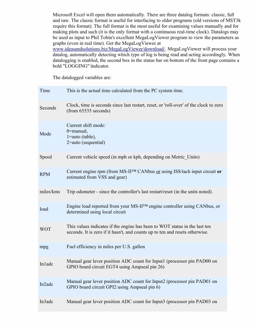
The datalogged variables are:
Time This is the actual time calculated from the PC system time.
SecondsClock, time is seconds since last restart, reset, or 'roll-over' of the clock to zero (from 65535 seconds)
Mode
Current shift mode:0=manual,1=auto (table),2=auto (sequential)
Speed Current vehicle speed (in mph or kph, depending on Metric_Units)
RPMCurrent engine rpm (from MS-II™ CANbus or using ISS/tach input circuit or estimated from VSS and gear)
miles/kms Trip odometer - since the controller's last restart/reset (in the units noted).
loadEngine load reported from your MS-II™ engine controller using CANbus, or determined using local circuit
WOTThis values indicates if the engine has been to WOT status in the last ten seconds. It is zero if it hasn't, and counts up to ten and resets otherwise.
mpg Fuel efficiency in miles per U.S. gallon
In1adcManual gear lever position ADC count for Input1 (processor pin PAD00 on GPIO board circuit EGT4 using Ampseal pin 26)
In2adcManual gear lever position ADC count for Input2 (processor pin PAD01 on GPIO board circuit GPI2 using Ampseal pin 6)
In3adc Manual gear lever position ADC count for Input3 (processor pin PAD03 on

GPIO board circuit EGT3 using Ampseal pin 25)
In4When 4 input channels are used to determine the shift lever position, this indicates whether that 4th input is high (=1) or low (=0)
solst
The state of Output1 is logged as the first bit of solst. The state of Output2 is logged as the second bit of solst. The state of Output3 is logged as the third bit of solst. The state of Output4 is logged as the 4th bit of solst, and so on. Zero inany position means off, 1 means on. So some examples are:
00000000 = 0 - Output1 off, Output2 off, Output3 off, Output4 through Output8 off00000001 = 1 - Output1 on, Output2 off, Output3 off, Output4 off,...00000011 = 3 - Output1 on, Output2 on, Output3 off, Output4 off,...00000101 = 5 - Output1 on, Output2 off, Output3 on, Output4 off,...00001000 = 8 - Output1 off, Output2 off, Output3 off, Output4 on,...00001010 = 10 - Output1 off, Output2 on, Output3 off, Output4 on,...00001100 = 12 - Output1 off, Output2 off, Output3 on, Output4 on,...00001111 = 14 - Output1 on, Output2 on, Output3 on, Output4 on,...... etc....
upbutton Indicates whether the upshift button has been pressed.
downbutton Indicates whether the downshift button has been pressed.
fUPIndicates whether an upshift is being forced by the rpm checking option Normally 0, this value will be 1 if a forced upshift is requested based on the current rpm (if 'rpm checking' is enabled).
fDWNIndicates whether a downshift is being forced by the rpm checking option. Normally 0, this value will be 1 if a forced downshift is requested based on the current rpm (if 'rpm checking' is enabled).
butADCWhen a voltage based shifter is used, this gives the current voltage level of the shifter input signal.
cGear Current selected gear determined from state of shift solenoids and output tables
tGear This is the gear the controller wants the trans to be in. Normally, it is the gear to shift to determined from shift table (limited by the manual gear lever

position as appropriate). On an under-rev or over-rev condition (if rpm checking is enabled), the target gear is set to the current gear ± 1. This value is still reported if shifting manually using the shift buttons, but the auto shift gear table value isn't used, of course
mGearManual gear lever position determined from switch manifold (GM style) or switch voltage (Ford style)
TCCTorque converter clutch state:0 = unlocked torque converter clutch,1 = locked clutch
BrakeBrake status:0 = brakes off,1 = brakes on
OS Current output shaft rpm, as determined from the VSS sensor output
IS Calculated or measured input shaft rpm
slip Difference in rpm between engine rpm and input shaft rpm
temp Transmission fluid temperature
line Line pressure in pounds per square inch or bars
auxCH Axillary data channel (used for load if no CANbus)
error error code:
bit & with meaning
0 0x01 = 1 1 = okay, 0 = serial communications error
1 0x02 = 20 = okay, 1 = no CANbus communications (load = 0.0)
2 0x04 = 4 0 = okay, 1 = under/over rev shift attempted
3 0x08 = 8 0 = okay, 1 = VSS reset occurred
4 0x10 = 160 = okay, 1 = other VSS error - no signal, excessive noisy/drop-outs (check tooth error counter)

5 0x20 = 32 0 = okay, 1 = gear out-of-range
6 0x40 = 64 0 = okay, 1 = low voltage (<10)
7 0x80 = 128
0 = okay, 1 = no brake signal (triggered only after exceeding 20 mph/kph and then going below 12 mph/kph without a brake signal being received at anypoint)
Ex1: error 11 = 1 + 2 + 8 = serial comms okay, no CANbus comms, VSS reset has occurred.Ex2: error 65 = 1 + 64 = serial comms okay, low voltage.
PC% Pressure Control valve duty cycle (% for PWM)
Sp0%
If spare port 0 is not used for a speedo output, this is the spare port 0 PWM percentage (from 0 to 100%). This value is interpolated from the 16x9 PWM Percent table if Sp0 is ON (OFF value if Sp0 is OFF). If spare port 0 is used for a speedo output, this is the shift status, where:
0. = no data 1. = shift completed - shift table 2. = shift completed - manual shift buttons 3. = shift completed - rev limit shift 4. = shift completed - manual gear lever position change 5. = shift blocked - under/over rev 6. = shift blocked - hysteresis not met 7. = shift blocked - manual lever position not found 8. = lower gear not available 9. = higher gear not available
Sp1%
Spare port 1 PWM percentage (from 0 to 100%). This value is interpolated from the 12x1 PWM Percent table if Sp1 is ON (OFF value if Sp1 is OFF), andthen the code picks the closest PWM% based on the number of 0.128 millisecond ticks available at the user specified frequency. So the returned percentage value may not exactly match the value expected from the table, especially if the PWM frequency is high. Click this link for more information.
Sp2%
Spare port 2 PWM percentage (from 0 to 100%). This value is interpolated from the 12x1 PWM Percent table if Sp2 is ON (OFF value if Sp2 is OFF), andthen the code picks the closest PWM% based on the number of 0.128 millisecond ticks available at the user specified frequency. So the returned percentage value may not exactly match the value expected from the table, especially if the PWM frequency is high. Click this link for more information.
sLoad Short term LOAD average

dbugSpare debugging variable brought out in TunerStudioMS (default is VSS tooth error count)
burn Indicates that a burn of users parameters to flash memory is active.
FWDstate of 2WD or 4WD switch for speedometer adjustment if enabled - 0 = 4WD, 1 = 2WD
sp0y
If spare port 0 is not used for a speedo output, this is the index value used for the 9 bin table for looking up the PWM percent for spare port 0. If spare port 0 is used for a speedo output, this is the TPS value received from the MS-II controller over CANbus.
sp0x
If spare port 0 is not used for a speedo output, this is the index value used for the 16 bin table for looking up the PWM percent for spare port 0. If spare port 0 is used for a speedo output, this is the raw speedo value before any correction from the speedo correction table.
Example: error 11 is 1 + 2 + 8 = serial comms okay, no CANbus comms, and VSS reset has occurred.Example 2: error 65 is 1 + 64 = serial comms okay, low voltage.
More variables are available for datalogging, you can find these in the [OutputChannels] section of the INI.
• Start Logging (CRTL-L) - starts a datalog. The runtime values will be saved to a file once you give the file a name. A default name is 'suggested' by TunerStudioMS, and has the format 'datalogyyyymmddhhiii.msl' (or .xls), where:
• yyyy is the year, • mm is the month (0-12), • dd is the day (0-31), • hh is the hour (0-24), and • ii is the minute (0-59),
all based on the time of creation of the datalog. The frequency of the datalog is set under 'DataRate' in the Communications dialog.
• Stop (CRTL-B) - stops the datalog from recording additional runtime variables.
• Burst Logging Mode datalog at the maximum speed the com port will support, regardless of the data rate set in the communications settings. This will result in very large datalogs in very short periods of time.
• Import/Conversion: Converts a datalog file. • Palm Import Utility: Converts a Palm log file. • Convert Binary Log (MS3/FRD): N/A
• View with MegaLogViewer: Opens a datalog file for viewing in MegaLogViewer. If you are actively datalogging, this will open the current datalog up to the point in time it is opened.
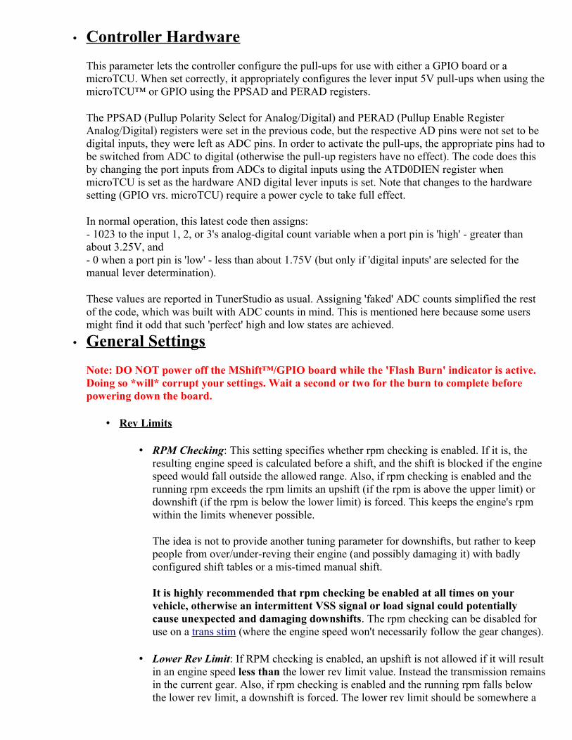
• Controller Hardware
This parameter lets the controller configure the pull-ups for use with either a GPIO board or a microTCU. When set correctly, it appropriately configures the lever input 5V pull-ups when using themicroTCU™ or GPIO using the PPSAD and PERAD registers.
The PPSAD (Pullup Polarity Select for Analog/Digital) and PERAD (Pullup Enable Register Analog/Digital) registers were set in the previous code, but the respective AD pins were not set to be digital inputs, they were left as ADC pins. In order to activate the pull-ups, the appropriate pins had tobe switched from ADC to digital (otherwise the pull-up registers have no effect). The code does this by changing the port inputs from ADCs to digital inputs using the ATD0DIEN register when microTCU is set as the hardware AND digital lever inputs is set. Note that changes to the hardware setting (GPIO vrs. microTCU) require a power cycle to take full effect.
In normal operation, this latest code then assigns:- 1023 to the input 1, 2, or 3's analog-digital count variable when a port pin is 'high' - greater than about 3.25V, and- 0 when a port pin is 'low' - less than about 1.75V (but only if 'digital inputs' are selected for the manual lever determination).
These values are reported in TunerStudio as usual. Assigning 'faked' ADC counts simplified the rest of the code, which was built with ADC counts in mind. This is mentioned here because some users might find it odd that such 'perfect' high and low states are achieved.
• General Settings
Note: DO NOT power off the MShift™/GPIO board while the 'Flash Burn' indicator is active. Doing so *will* corrupt your settings. Wait a second or two for the burn to complete before powering down the board.
• Rev Limits
• RPM Checking: This setting specifies whether rpm checking is enabled. If it is, the resulting engine speed is calculated before a shift, and the shift is blocked if the engine speed would fall outside the allowed range. Also, if rpm checking is enabled and the running rpm exceeds the rpm limits an upshift (if the rpm is above the upper limit) or downshift (if the rpm is below the lower limit) is forced. This keeps the engine's rpm within the limits whenever possible.
The idea is not to provide another tuning parameter for downshifts, but rather to keep people from over/under-reving their engine (and possibly damaging it) with badly configured shift tables or a mis-timed manual shift.
It is highly recommended that rpm checking be enabled at all times on your vehicle, otherwise an intermittent VSS signal or load signal could potentially cause unexpected and damaging downshifts. The rpm checking can be disabled for use on a trans stim (where the engine speed won't necessarily follow the gear changes).
• Lower Rev Limit: If RPM checking is enabled, an upshift is not allowed if it will resultin an engine speed less than the lower rev limit value. Instead the transmission remainsin the current gear. Also, if rpm checking is enabled and the running rpm falls below the lower rev limit, a downshift is forced. The lower rev limit should be somewhere a

bit below your lowest cruise rpm. • Upper Rev Limit: If RPM checking is enabled, a down shift is not allowed if it will
result in an engine speed greater than the upper rev limit value. Instead the transmission remains in the current gear. If it is enabled and the running rpm rises above the upper rev limit, an upshift is forced. The upper rev limit should be set to the redline (maximum rpm) of the engine.
• Force Auto Mode: This allows the user to set the circumstances when auto mode is selected from manual mode without user intervention (i.e. without using the shift buttons to select auto mode). The options are:
• In PNR OR under OR over rev: Switch to Auto mode if the manual gear lever ischanged to Park, Neutral or Reverse OR if the engine exceeds the maximum revlimit OR the engine falls below the minimum rev limit.
• Only if over rev: Switch to Auto mode ONLY if the engine exceeds the upper rev limit.
• Only if under rev: Switch to Auto mode ONLY if the engine drops below the lower rev limit.
• Only in PNR: Switch to Auto mode ONLY if the manual gear lever is changed to Park, Neutral or Reverse.
• Only if under OR over rev: Switch to Auto mode if the engine drops below the lower rev limit OR if the engine exceeds the maximum rev limit.
• Gear Ratios
You must enter the gear ratios built into the transmission. • Number of forward gears: This is the number of forward gears in the transmission.
This parameter is used to prevent the transmission from trying to shift to a gear that thetransmission does not have, and it is also used to limit the number of inputs available under the InputX Patterns and OutputX Patterns in the tuning software.
• First Gear: Gear ratio (x.xxx : 1) for first (1st) gear. • Second Gear: Gear ratio (x.xxx : 1) for second (2nd) gear. • Third Gear: Gear ratio (x.xxx : 1) for third (3rd) gear. • Fourth Gear: Gear ratio (x.xxx : 1) for fourth (4th) gear. • and so on up to the number of forward gears... • Reverse Gear: Gear ratio (x.xxx : 1) for reverse (R) gear.
• Shift Factors
• Auto Shift Mode: This can be sequential or skip-shift. Sequential always shifts to the next higher or lower gear, and completes that shift before attempting another shift. Skip-shift will go directly to the target gear, skipping any intermediate gears if necessary. Skip-shift may be faster, but may upset the vehicle dynamics.
• Burnout Mode (D2) Usage: Options to use either 'Use 1st and 2nd' (default), or 'Use 2nd Only (burnout mode)'. The chosen option only applies when in auto mode. If 'Use 2nd Only (burnout mode)' is selected, then whenever the lever is in 2nd (aka. D2) the trans will stay in 2nd and not shift to 1st at all.
Enabling burn-out mode effectively makes the trans manually shifted with the lever in the 1st (since the highest gear will be 1st) and 2nd positions (burn-out mode), and then the trans will be automatically shifted according to the shift table if the lever is in 3rd or 4th (or higher if your trans has more gears).

Note that in burnout mode the MShift™ code's rev limiter settings will be ignored. • Minimum Manual Speed: This the the minimum speed allowed in manual mode,
traveling slower than this will force the transmission into auto mode. Note that in addition to a speed between 0 and 15 mph, you can set this to:
• 0.0 = shift to auto mode only if you stop, or • -1.0 = shift to auto mode only if both shift buttons are pressed or if the rev
limits are exceeded. • Shift Button Duration: This is the number of main loop cycles (at approx 5000
loops/second) that it takes for the shift button activation to be recognized while continuously pressed. Larger number slow the shift response, but filter more noise out of the signal. The code then won't let you shift again until you have released both shift buttons for 1/4 of the user-set 'shift button duration'. This prevents a single button press from causing multiple shift up or down.
• Digital Switch Debounce: This is the number of times the gear lever determination switches must be the same before the controller will consider it to be 'certain' of the switch state and establish the gear lever position. Unlike older code (which ran from 0 to 255) this value can be as high as 65535. The default in the V4 code is 400 (compared to 80 in the V2 code).
• LOAD Smoothing Factor: This is a factor used to average the load readings to help geta true sense of the driving style and thus help prevent the transmission from 'hunting' gears. It can be from 1 to 4000. Higher numbers result in longer averaging periods (andless fluctuation).
• Max. Shift Line Pressure: This sets the maximum line pressure during a shift (in units of 100%-line pressure duty cycle%). High line pressures result in faster shifts, but are harder on the transmission internal parts. The 4L60E is not noted for being tolerant of very high line pressure during shifts.
• Shift Pressure Adjustment Delay: This is the period of time controller waits before a shift to allow the line pressure change to take effect (and for the TCC to disengage if necessary).
• Shift Completion Delay: This is the period of time the controller waits after changing the shift solenoid states for the shift to complete. No further shift computations are made during this period.
Shift Hysteresis: The shift hysteresis parameters below will prevent shifts until the speed or load has changed (from the speed/load at the most recent shift) either up or down by the hysteresis value. The default speed hysteresis is 3.5 mph. If the last shift was at 60 mph and the load doesn't change, another shift won't be allowed until the speed reaches either 63.5 mph or 56.5 mph (at which point a shift will be allowed according to the gear table). The intent is to prevent noise in the vehicle speed signal orload signal from causing the controller to jump back and forth if the speed load hovers around a shift point.
• Shift Speed Hysteresis: A shift will not be attempted until the vehicle speed has changed by at least the shift speed hysteresis amount (in mph or kph, depending on the 'Metric/Imperial Units' setting) since the last shift.
• Shift Load Hysteresis: A shift will not be attempted until the engine load has changed by at least the shift hysteresis amount since the last shift. If MAP is used as the load, then the hysteresis value is in kiloPascals (kPa), if TPS is used as the load, then the hysteresis value is in percent (%).
• Hysteresis Enable Speed: No hysteresis is used below this speed.
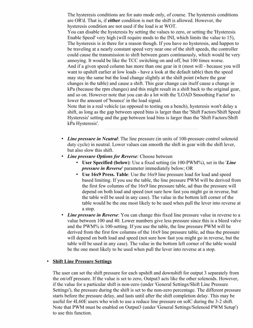
The hysteresis conditions are for auto mode only, of course. The hysteresis conditions are OR'd. That is, if either condition is met the shift is allowed. However, the hysteresis condition are not used if the load is at WOT. You can disable the hysteresis by setting the values to zero, or setting the 'Hysteresis Enable Speed' very high (will require mods to the INI, which limits the value to 15), The hysteresis is in there for a reason though. If you have no hysteresis, and happen to be traveling at a nearly constant speed very near one of the shift speeds, the controller could cause the transmission to shift between gears continuously, which would be very annoying. It would be like the TCC switching on and off, but 100 times worse. And if a given speed column has more than one gear in it (most will - because you will want to upshift earlier at low loads - have a look at the default table) then the speed may stay the same but the load change slightly at the shift point (where the gear changes in the table) and cause a shift. This gear change can itself cause a change in kPa (because the rpm changes) and this might result in a shift back to the original gear, and so on. However note that you can do a lot with the 'LOAD Smoothing Factor' to lower the amount of 'bounce' in the load signal. Note that in a real vehicle (as opposed to testing on a bench), hysteresis won't delay a shift, as long as the gap between speed bins is larger than the 'Shift Factors/Shift SpeedHysteresis' setting and the gap between load bins is larger than the 'Shift Factors/Shift kPa Hysteresis'.
• Line pressure in Neutral: The line pressure (in units of 100-pressure control solenoid duty cycle) in neutral. Lower values can smooth the shift in gear with the shift lever, but also slow this shift.
• Line pressure Options for Reverse: Choose between • User Specified (below): Use a fixed setting (in 100-PWM%), set in the 'Line
pressure in Reverse' parameter immediately below; OR • Use 16x9 Press. Table: Use the 16x9 line pressure load for load and speed
based limiting. If you use the table, the line pressure PWM will be derived fromthe first few columns of the 16x9 line pressure table, ad thus the pressure will depend on both load and speed (not sure how fast you might go in reverse, but the table will be used in any case). The value in the bottom left corner of the table would be the one most likely to be used when pull the lever into reverse ata stop.
• Line pressure in Reverse: You can change this fixed line pressure value in reverse to a value between 100 and 40. Lower numbers give less pressure since this is a bleed valveand the PWM% is 100-setting. If you use the table, the line pressure PWM will be derived from the first few columns of the 16x9 line pressure table, ad thus the pressure will depend on both load and speed (not sure how fast you might go in reverse, but the table will be used in any case). The value in the bottom left corner of the table would be the one most likely to be used when pull the lever into reverse at a stop.
• Shift Line Pressure Settings
The user can set the shift pressure for each upshift and downshift for output 3 separately from the on/off pressure. If the value is set to zero, Output3 acts like the other solenoids. However, if the value for a particular shift is non-zero (under 'General Settings/Shift Line Pressure Settings'), the pressure during the shift is set to the non-zero percentage. The different pressurestarts before the pressure delay, and lasts until after the shift completion delay. This may be useful for 4L60E users who wish to use a reduce line pressure on solC during the 3-2 shift. Note that PWM must be enabled on Output3 (under 'General Settings/Solenoid PWM Setup') to use this function.

• Upshift to 2nd: This is the line pressure setting for the upshift to 2nd gear, • etc. ...
• Throttle Factors
• WOT TPS Threshold: The TPS value (from MS-II over CANbus) above which the MegaShift™ code determines you are at full throttle, so it skips the LOAD averaging and uses the current LOAD value. The shift hysteresis values are also ignored if the WOT TPS Threshold is exceeded. Both of these actions speed downshifts.
• Idle TPS Threshold: The TPS value (from MS-II over CANbus) below which the MegaShift™ code determines you are at idling (if the speed is also zero and the transmission is in 1st gear), so applies the the Idle-Up timing and IAC adjustments.
• WOT Duration: This is the time after the throttle is open fully that hysteresis is disabled. It can be set from 0 to 20 seconds. The default is zero.
• Solenoid PWM Setup
Note that fully variable PWM is enabled only on the PC (pressure control) valve in the default 4L60E configuration. This valve has a 1N4001 recirculation diode installed externally between the solenoid power supply and the line to the GPIO board to recirculate the flyback current generated by the PWM. The illustrated instructions are here: Recirculation Diode Instructions. If you enable PWM on Output1, Output2, Output3, Output4, and/or TCC you MUST install an external 1N4001 recirculation diode between that solenoid's voltage supply and the line going to the GPIO board. The banded end of the diode goes to the voltage supply wire, the non-banded end of the diode goes to the line to the GPIO board. Install the diode as close to the solenoid as is convenient. The 1N4001 diode is installed externally to avoid bringing high-voltage noise into the controller. 1N4001 diodes are available at virtually any electronics supply shop. Without this external diode in the PWM circuits, you may damage some internal components.
• PC PWM Period: This is the period, in milliseconds, for the pressure control (PC) solenoid pulse width modulation. You can enter a value between 0.427 and 10.888 (92

Hertz to 2340 Hertz) - the tuning software may round the value up or down slightly to be compatible with the processor's timer set-up.
• PC Voltage Correction: This is the battery voltage correction factor for the pressure control solenoid. Lower voltages require longer PWM duty cycles to achieve the same line pressure. This factor lets you set how much duty cycle (as an additive percentage) is added to the pressure control duty cycle below 12 Volts (or subtracted above 12 Volts).
• Output3 PWM Period: This is the period, in milliseconds, for Output3 (the 3-2 shift control solenoid) pulse width modulation. You can enter a value between 0.850 (0.000850 sec = 1176 Hertz) and 21.000 (0.021 msec = 48 Hertz) - the tuning softwaremay round the value up or down slightly to be compatible with the processor's timer set-up. Not that in the default settings for the 4L60E, Output3 operates only at 0% PWM or 90% PWM.
• Output3 DC when ON: When Output1 is 'on' the DC will be set to the specified value (the frequency can be set under 'General Settings/Solenoid PWM Set-Up/Output3 PWM Period')
• Output1,2,4,5 and 6 PWM Parameters: The code makes it possible to 'bit-bang' up to 5 of the outputs to get PWM current limiting. The 'bit-bangable1' outputs are:
1. Output1 = PE4, 2. Output2 = PM2, 3. Output4 = PA0, 4. Output5 = PAD01, 5. Output6 = PAD03.
To set the code up to use PWM on Output1, Output2, Output4, Output5 and Output6 you need to set the on and off times:
• Output1/2/4 ON Period: this is the time the signal is high, and is specified in multiples of 0.128 milliseconds (0.000128 seconds).
• Output1/2/4 OFF Period: this is the time the signal is low, and is specified in multiples of 0.128 milliseconds (0.000128 seconds). The user parameters can range from zero up to 255. The shortest period we can have is 2*0.128 = 0.256 for a frequency of 1/0.000256 = 3906 Hertz. The lowest PWM frequency will be 1/((255+255)*0.000128) = 15 Hertz (at 50% duty cycle). So the range will be 15 to 3906 Hertz. Note that the longer the period (the smaller frequency), thegreater the PWM percentage resolution becomes.
Here is a calculator to help set the ON and OFF parameters based on the target frequency and duty cycle:
TargetFrequency (Hz)
Target DutyCycle
Set ON Period =Set OFF Period
=Actual
FrequencyActual Duty
Cycle
Hz %
You can select which of the outputs (1,2,4,5,6) have PWM, and which are on/off in thismenu as well. Note that Output3 is controlled independently.
Compute Parameters Reset

Also see: PWM Refresh and Dithering
• VSS Setup
• Number of VSS Teeth: The number of teeth on the output shaft gear wheel for the vehicle speed sensor to read.
• Input Capture Edge: This can be rising edge or falling edge. the best way to set it is to use an oscilloscope on the VSS sensor to see which of the transitions are steeper, then set the input capture edge to the opposite (since the VR input circuit on the GPIO boardinverts the signal). However, you can also set it by noting which setting gives the steadiest and most reliable VSS reading in TunerStudioMS.
• VSS Input Masking: The general rule for the mask setting is that when: • the speed drops unexpectedly, the mask needs to be higher to allow more of
the signal to be used, and • the speed jumps unexpectedly the mask needs to be lower to reject false
signals.
The masking is set as the average of the last 20 periods plus or minus the user input percentage. The lower limit is the average period minus (input_mask/2); the upper limit is the average period minus input_mask. For example, if you enter 33%, and the current count for the 20 periods is 1440 (= 1440/20 = 72 tics/tooth), then the mask is set to accept periods from 72-(33%/2) = 72-(0.165*72) = 60 tics to 72+33% = 96 tics. So the range is not based on 100% being no filtering. Instead, low numbers mean more filtering, high numbers mean less filtering (the INI limits the range to a maximum of 200% - higher numbers will break the code).As of 2.122 code, you can disable the VSS input signal masking by setting this value to zero (0). This may help with speedometer gauges that become jittery, spastic or stuck. If you do not set this value to zero, set it to at least 50. Values lower than 50 may cause the speedometer to respond very slowly.

• VSS Smoothing Factor: This factor reduces the effect of noise in the VSS signal. The factor ("VSSsmoothFactor") works like this:
new speed =( current speed * (VSSsmoothFactor - 1) + newspeed)/VSSsmoothFactor
The default VSSsmoothFactor is 4, so if the current speed is 20 and the VSS indicates it has risen instantaneously to 25 (usually because of noise), the calculation is:
new speed =( 20 * (4-1) + 25)/4 = (60+25)/8 = 21.2 mph
The controller recalculates this 100 times per second, so the 'real' speed can still rise or fall quite rapidly. The smoothing factor can be from 2 to 12 (limited in the INI file).
VSS smoothing is disabled if the current vehicle speed is less than 1.5 times the 'Min. Vehicle Speed' (below) to prevent the speedometer from being stuck at zero if the minimum speed is high.
• Max. Vehicle Speed: This is the maximum vehicle speed. Lower numbers will significantly improve the filtering of noise from the VSS signal. However, the speedometer will be railed at the number you enter, so it must cover the actual top speed of the vehicle under the conditions you are driving (though you can change it from one situation to another if you need to, of course). Try to set this value 5 to 15 mph (or 10 20 kph) above your vehicle's actual maximum speed, because the speedometer can act strangely if the max speed is reached while running.
• Min. Vehicle Speed: This is the minimum vehicle speed. Higher numbers will improvethe filtering of noise from the VSS signal. However, the speedometer will not register lower speeds.
• Max. Errors to Reset: This is the number of 'bad' VSS signals (those that fall outside of the mask above) that trigger a complete reset of the VSS settings. Lower numbers will reset more often, and keep the VSS from freezing, but may allow more 'false positive' signals to register. After a reset, all VSS 'history' is deleted, and all VSS filtering is disabled for a few seconds (the time is set below). Higher numbers will allow for more filtering (the filtering will continue even as bad teeth are registered, up until a reset occurs), but may allow errors conditions to persist for longer.
• Reset Filter Off: This is the length of time that VSS filtering is greatly reduced after a reset. Longer times allow the signal to be picked up, but may allow a lot of noise and false triggers. Shorter times prevent the VSS signal from climbing out of control.
• Axle Ratio: Drive axle final gear ratio (x.xxx : 1). • Tire Diameter: Rolling diameter of the tire (in inches if you have set the units to
Imperial, in centimeters if you have set it to Metric). • 4WD Speedo Correction: This is the dividing factor applied to the speedometer when
4WD is engaged (if GPI1/Amp5 INPUT Usage is set to use that pin as a 2/4WD selector, and is pulled low to indicate 4WD operation).
• MPG Settings
These fuel efficiency factors allow MegaShift™ to compute the instantaneous fuel consumption.
• Injector Flow Rate: The is the flow rate of the injectors used in MS-II™, in pounds perhour (aka. 'pph' or 'lb/hr')
• Injector Open Time: This is the injector open time used in MS-II™, in milliseconds. • Fuel Density: This is your fuel's density in lb/gal. Typically, this is 6.073 for gasoline.

• Number of Squirts: This is the number of squirts used in MS-II™.
• Timing Adjustments
Timing retard values are positive to remove timing from the MS-II™ engine controller spark advance table. Retard values are applied for the duration of the shift, which includes the 'shift pressure adjustment delay' and the 'shift completion delay' times (under 'General Settings/ShiftFactors'), plus the very short time required to process the shift solenoid switching.
• Retard only above: The timing will only be retarded in an upshift or downshift or in 2nd gear or higher if the load is greater than the value entered here.
• Upshift Retard: This amount of timing retard will be applied to MS-II's spark advance table setting for the duration of an upshift to reduce power (to protect the transmission and/or to prevent wheel spin). The duration is defined by the shift factors. For example,5.0 will give 5° of retard from MS-II's spark advance table setting during upshifts.
• Downshift Retard: This amount of timing retard will be applied to MS-II's spark advance table setting for the duration of a downshift to reduce power (to protect the transmission and/or to prevent wheel spin). The duration is defined by the shift factors. For example, 5.0 will give 5° of retard from MS-II's spark advance table setting during upshifts.
• 2nd Gear Retard: This amount of timing retard will be applied while in 2nd gear if the load is above the 'retard only above' value entered above. This allows more timing and better acceleration in lower gears (where rpm is rising rapidly and detonation is less likely), while preventing detonation with reduced advance in higher gears where the rpm increase rate is much lower.
• 3rd Gear Retard: This amount of timing retard will be applied while in 3rd gear if the load is above the 'retard only above' value entered above. This allows more timing and better acceleration in lower gears (where rpm is rising rapidly and detonation is less likely), while preventing detonation with reduced advance in higher gears where the rpm increase rate is much lower.
• and similar for the remaining forward gears... • Slip Based Retard and Fuel Adjustments:: These are the adjustments available if
using an ISS: • Min. Load for Slip Based Retard: Slip adjustments are only send to the engine
ECU if the current engine load is above the threshold specified here. • Retard When Slip Detected: This is the amount of ignition retard to apply to the
engine ECU's commanded spark advance when the load and slip conditions are met.
• Fuel Adjustment When Slip Detected: This is the amount to adjust the engine fuel pulse width on the engine ECU when the load and slip conditions are met.
• Min. Slip for Adjustments: This is the minimum amount to slip before the slip adjustments are sent to the engine ECU. Below this level of slip, the adjustments are not sent, they are ignored.
So, for example, if you shift from 1st to 2nd, and the upshift retard is 10°, and the second gear retard is 2°, with a base timing of 20° you would see on the timing gauge:
• initially 20° while in 1st before the shift, • then 10° (20°-10°) for the duration of the shift if the load is high enough (greater than
the user setting), • then 18° (20°-2°) while in 2nd for as long as the load threshold was met.
Assuming slippage is always below the Min. Slip for Adjustments, of course. If slip was above

that level, then additional adjustments would come into play, of course.
These timing adjustments have been extensively tested with MS-II™ and B&G code, where they work perfectly. Apparently these timing adjustments do not work in MS3 as of Nov.23, 2011, presumably due to a bug in the CANbus code for MS3. Contact the MS3 developers on their forum at www.msextra.com to see if this bug has been fixed at the time you read this.
• Idle-Up Adjustment
• Timing Adjustment: The value entered here will be added to the ignition timing advance in MS-II when stopped in 1st gear (and the TPS very low). Positive values mean the timing will be advanced. Adding advance when stopped may help prevent stalling in gear in some installations. Set to zero to disable.
• Idle Valve Adjustment: The value entered here will be added to the idle valve value in MS-II when stopped in 1st gear (and the TPS very low). This value is in percent (%) if the engine controller is configured to use a PWM Idle Valve, and it is in steps if stepper IAC is specified in MS-II. The value entered can be positive or negative. Use with caution, you do not want to apply too much IAC, as this may make the vehicle want to move forward when stopped. Set to zero to disable.
• Standard Inputs/Outputs Configuration
• Temperature Sensor Usage: the temperature sensor input (processor pin PAD02 on circuit GPI3 using Ampseal pin 30) has three options:
• log the temperature only, do not use it in any control functions. This can be used to measure and log a variable 0-5V signal.
• use it to control the trans functions as on the 4L60E (things like force TCC lockin certain gears above a specific temperature).
• Temperature Sensor Logging: It can be used to log a voltage signal (0-5V, or higher ifthe circuit is built appropriately). This could be used for a number of things, including troubleshooting outputs.
• Log the temperature only, do not use it in any control functions (still uses the cltfactor.inc table to convert to degrees),
• Log the raw ADC count only (and convert to voltage, etc. in the INI file). Canbe used only if not using the sensor for transmission temperature monitoring. If you are using a variable resistance sensor with this input, you might want to see: www.msgpio.com/manuals/mshift/adccalc.html
• Line Pressure Input: This lets you choose between: • Use pressure table as determined from the ADC count using the line pressure
values for the Digikey MSP6907-ND for $114. This sensor has a 0.5-4.5 Volt output (accuracy ±5 psi), and has just a three wire hookup:
1. 5V from Vref on Ampseal pin #28, 2. Ground, and 3. Signal to Ampseal pin #27.
This sensor has a 1/8" NPT fitting. However, a 90° elbow, or maybe even some tubing, will be required in most installs to keep the sensor away from the transmission tunnel. Note that other internal values can be burnt to the controller to accommodate other sensors, but it might be easier to convert the ADC count in the tuning software.

• Use as Engine Brake Input: Use the line pressure as a jake brake input to sense that a diesel engine compression brake ("jake brake") is activated and consequently apply the TCC and maximum line pressure. The brake is considered 'activated' if the voltage drops below approximate 0.24 Volts (an ADC count of 50). This is done by grounding Ampseal connector pin 27 through a suitable switch when the brake is active. The minimum TCC speed and minimum TCC gear still apply, so you must consider those parameters carefully for this application. The ADC count value of the line input at all timeswill be reported in the datalog.
• Use 2-Point Calcs: You can set the 2-point pressure sensor calibration values. Unlike the temperature sensor, the pressure sensor is not calibrated in TunerStudio. Instead, you can either use the default response 'curve', or log the ADC directly and convert it using a formula in TunerStudio. If you have a linear response from your sensor (the graph of the output is a straight line), thenyou can use that tho calibrate MShift to report the pressure correctly.
For example: Suppose 0bar = 0.5v and 20bar = 4.5 volt.
There are 1024 ADC count to cover 0.0 to 5.0 Volts. So:0.5V = 0.5/5.0*1024 = 102 ADC counts, and4.5V = 4.5/5.0*1024 = 922 ADC counts.
So the pairs we have are:(102 counts, 0 Bar) and (922 counts, 20 Bar).
The slope is then:m = rise/run = (20 - 0)/(922-102) = 20/820 = 0.0244 Bar/count
The y-intercept is:b = y - mx = 20 - 0.0244*922 = 20 - 22.488 = -2.488 Bar (this is the theoretical pressure when the Voltage is zero (if everything was linear).
This sets up a pressure sensor based on two (voltage, pressure) points. All the slope/intercept calculation is done internally, so the user doesn't have to do the math. There are four parameters, corresponding to two points:
1. Voltage at Point1: 2. Pressure at Point1: 3. Voltage at Point2: 4. Pressure at Point2:
The further apart the two points are, the more accurate the reported pressure will be.
You can use the 2 point setting to report the Analog-Digital Conversion (ADC) count on the line pressure input by changing the settings to:

You can read more about ADC counts here: www.msgpio.com/manuals/mshift/adccalc.html
Also, there is no dedicated gauge for the ADC output, you would have to create one. It would look something like this (add it to the [Gauges] section of the INI):
line_ADC = linepressure, "Pressure ADC", "", 0, 1023, 1, 5, 1020, 1024, 0, 0
• Shift Button Polarity: This user setting is to set the shift button active action. The user can set whether the button is considered 'pressed' if the CPU pin is grounded (as before,and still the default = "active low"), or ~5 Volts ("active high" with grounded being 'off').
• Brake Signal polarity: This lets you tell the processor if the brakes are on when it sees 12V or 0V on the input (processor pin PAD07 on circuit GPI4 using Ampseal pin 3). This allows for connecting the a stop lamp bulb that is powered by the brake switch and grounded at the lamp (typical of older cars), or a bulb that is always powered by 12V and grounded by the stop switch (more typical of newer cars). The default is HIGH for brake ON.
• PWM Refresh and Dithering
Some PWM solenoids uses a deliberately low PWM percent, but refresh the solenoid with a burst at 100% before it can close. As well, some pressure control solenoids use a cleaning pulse (called a 'dither') to ensure adequate fluid flow through the system to keep the system clean. You can set both of these up in this dialog.
• PWM Refresh Interval: the time, in milliseconds, between refresh pulses on Output1, Output2, and Output4.
• PWM Refresh Duration: the time, in milliseconds, that refresh pulses are held high (100% duty cycle) on Output1, Output2, and Output4, set to zero to disable,
• PC Dither Interval: the time, in milliseconds, between dither pulses on the PC output (processor pin PT2 on circuit PWM3 using Ampseal pin 33),
• PC Dither Duration: the time, in milliseconds, that refresh pulses are held high (100%duty cycle) on the PC output = solC (processor pin PT2 on circuit PWM3 using Ampseal pin 33), set to zero to disable.
• ISS/non-CANbus Tach Settings
• ISS/Tach Input Usage: Here you can choose between using the input (processor pin PT5 on circuit VR3 using Ampseal pin 14) for an input shaft speed sensor input, a tachometer input (if not using CANbus to get the RPM from MS-II), or neither.
• TCC/Trans Slip Reporting: Choose whether to report either converter slip or internal slip (only available if using ISS). Furthermore, user settable spark advance and fuel adjustments (General Settings -> Timing and Fuel Adjustments -> under Slip Based Retard and Fuel Adjustments) have been put in place when:
• slip is above a user set threshold (100% is no slip, anything else is slip, where slip is defined as (ISS/(VSS*internal gear ratio)) * 100%
• CANbus is enabled, • an ISS input is activated (General Settings -> ISS/non-CANbus Tach Settings

-> ISS/Tach Input Usage), • a minimum user-set load threshold is achieved. • the trans is not shifting (i.e. the controller is in neither of the pre-shift 'pressure
adjustment delay' nor the post-shift 'shift completion delay', both of which are existing user settings.
• Pulses/Revolution: The number of pulses per revolution (per crankshaft if using the input as a tach input, or the number of pulse per input shaft revolution if using as an input shaft speed input).
• Input Mask: A pulse will be rejected if is is not within the Input Mask% of the averageof the last 20 pulses. So lower numbers mean more filtering, larger numbers mean less filtering. You might have to play around with this to get a value that works for your installation. As of 2.122 code, you can disable the VSS input signal masking by setting this value to zero (0). This may help with inputshaft speed/tach gauges that become jittery, spastic or stuck. If you don't set this value to zero, set it to at least 50. Lower values may cause the ISS tach to respond very slowly.
• Input Capture Edge: You can set the code to recognize the rising or falling edge of thesignal. In general, the VRx circuits are designed to send the rising edge as the trigger edge, but you might need to change this setting in some cases.
• non-CANbus Load Calibration MegaShift™ can read the engine load from a MegaSquirt-II™ controller over the CANbus network. If the CANbus network is not used, a 0 to 5 Volt signal can be used to indicate the load to MegaShift™. This can come from a MAP sensor, TPS, MAF, or other load related device. MegaShift™ translates the voltage on the load device into a 0-100 value load signal. You specify two values to tell MegaShift™ how to do this:
• Multiplier: The translation is:
Load = ('Multiplier' * deviceVolts) + 'Load at 0 Volts'
• Load at 0 volts: This is the 'y-intercept' of the device response line.
To calculate these factors, we want to fit two points [(Volts1, Load1),(Volts2, Load2)]
to a line with the equation of the form:
y = Mx + B
Where M = multiplier (aka. "slope" in math terms), x is the Volts, B = Load at zero Volts, and y = load.
M is the slope, which is the 'rise' divided by the 'run':
M = (Load2 - Load1)/(Volts2 - Volts1)
and B = Load1 - M * Volts1

For example, if your device puts out 1.2 Volts at 20% load, and 4.4 Volts at 100% load, then the values you would use are:
Multiplier = (100-20)/(4.4-1.2) = 80/3.2 = 25Load at 0 Volts = B = y - Mx = Load1 - 25*Volts1 = 20 - (25*1.2) = -10
The equation then becomes Load = (25 * Volts) - 10
Here is a calculator to assist in deriving the values (click anywhere outside a text box to recalculate):
Low Load: % Signal Voltage: V
High Load: % Signal Voltage: V
Load at 0 Volts: = (aka. Y-Intercept)
Multiplier = (aka. Slope)
• Error Behavior • On Error: You can choose to report errors in the gauge and datalog, or ignore them.
Choose either 'Report Errors' to have the error conditions reported in TunerStudio and responded to by the code, or 'Ignore errors' to ignore these errors. The 'On Error' settingdoes not include VSS errors (missing or extra teeth, and the resets they eventually cause) or shift lever errors, which are handled separately (lever errors below, VSS error in the VSS setup).
• Lever Error Behavior: Allows the user to turn off the gear lever error checking. If the checking is turned off, the last known 'good' lever position is used until another good lever position is established. If the checking is on, lever errors are reported once the

'Lever Error Delay' has elapsed. The default is to check for errors. • Lever Error Delay: Set a time during which lever errors are ignored (the default is 2.0
seconds, the values can range from 0.3 to 25.5 seconds). When a gear error occurs, a timer is started. Until the timer period expires the last known valid gear lever position is reported and used by the code.
• Shift Input Patterns
Note: DO NOT power off the MShift™/GPIO board while the 'Flash Burn' indicator is active. Doing so *will* corrupt your settings. Wait a second or two for the burn to complete before powering down the board.
• Lever and Shift Button Configuration: Here you can set how the three (or 4 if configured for 4 digital inputs) inputs (SwA, SwB, SwC on the 4L60E) will allow the code to determine the manual gear lever position. The defaults are for the 4L60E/4L80E transmissions. Alternately, you can set your MShift™ up to use a single 'variable voltage' input to determine the manual gear lever position.
You can also choose whether you will use two grounding switches for manual shifting and mode changing, or whether you will use a variable voltage shift request scheme instead.
• Manual Lever Mode: This dialog also lets you set the gear shift lever sensor type. Thiscan be either digital (on/off) inputs (" digital switches (GM)") for transmissions that operate like the GM 4L60E, or a single variable voltage ("Voltages (Ford)") like some Ford transmissions. If you use a voltage based shift lever input, you set the voltages under 'Shift Input Patterns/Configure Inputs'.
• Max. Lever Position Change: This is the maximum number of lever positions that are considered valid for a single lever position shift (in forward gears only). This will prevent the reporting a misleading lever position if an invalid state is briefly attained between valid positions.
• Digital Voltage Threshold: If you elect to use digital inputs, then you can set the threshold voltage for the switches. If the voltage is below the threshold, the input is considered "low", otherwise it is "HIGH".
• Shift Button Mode: You can choose either 'Grounding Switches' (two separate switches, one for upshift and one for downshift, that ground their respective outputs) or'Discrete Voltages' (4 voltage levels that define the current buttons pressed). See this link for more information on the voltage based shifter.
• No Buttons pressed: This is the signal voltage that signifies that no buttons are pressed(plus or minus the button voltage tolerance).
• Upshift buttons pressed: This is the signal voltage that signifies that the upshift button is pressed (plus or minus the button voltage tolerance), but not the downshift button.
• Downshift buttons pressed: This is the signal voltage that signifies the downshift button is pressed (plus or minus the button voltage tolerance), but not the upshift button.

• Both buttons pressed: This is the signal voltage that signifies that both buttons are pressed (plus or minus the button voltage tolerance).
• Button voltage tolerance: This is the range of acceptable voltage variation that will still match the above voltages.
If the tolerance is set so that the valid ranges overlap, the code will select the first button state that is within the tolerance in the following order:
• Neither buttons pressed, • Both buttons pressed, • Upshift button pressed, • Downshift button pressed.
This may not be what you want, so be sure to set the voltage tolerance carefully.
• Input Patterns:
NOTE: You must only change the input patterns 'off-line' - then load that MSQ to your MShift™ controller once you are sure the patterns are appropriate. This is because you must make sure the entered patterns do not have the same pattern for more than one gear including reverse (except that park and neutral can and should have the same pattern, but different from all the other gears - the code does not distinguish between these), or MShift™ will NOT work. The code will not operate the solenoids correctly, and the flash memory burn process might be corrupted. Note that the input patterns are not 'tuning parameters', you must set them correctly and them leave them.
So, for example, if you have entered the same pattern for Reverse and 3rd, then the code will always assume 3rd gear when that pattern is sensed. The code will never be able to determine that you are in Reverse, regardless of the actual physical position of the gear lever.
You need to specific the state (high or low) of each input in each gear. To edit the bit pattern individually in each gear:
• Input1: This is Input1 (processor pin PAD00 on circuit GPI1) for the switches that are used to determine the manual gear lever position.
• Input2: This is Input2 (processor pin PAD01 on circuit GPI2) for the switches that are used to determine the manual gear lever position.
• Input3: This is Input3 (processor pin PAD03 on circuit EGT3) for the switches that areused to determine the manual gear lever position.
• Input4 (if set): This is Input4 (processor pin PE1 on circuit GPI1 using Ampseal pin AMP5) for the switches that are used to determine the manual gear lever position.
• Configure Inputs: If you are using a variable voltage in shift lever input above, then you can configure the voltages for each gear in this dialog. For the voltages, specify the middle of the voltage range in each gear. MShift™ will calculate the voltage range for each gear after being reset. These voltage are based on an input range of 0-5 Volts, if you are using some other sort of signal (0-12V, for example), you must use a voltage divider circuit (consisting of 2 resistors) to bring the voltage into a 0-5 Volt range, otherwise you will damage the processor.
The voltages ranges are set dynamically so that the split point is 1/2 way between the adjacent voltages. There is a dead band applied (the voltage must be at the 1/2 way point plus the dead band for the lower voltage, and minus the dead band for the higher voltage. The default dead band is 5 ADC counts, which is 5/1024*5.0 = 0.0244 Volts

For example, if you have voltages set at:
1st: 1.00V
2nd: 2.00V
3rd: 3.00V
... ...
Voltage Dead Band 0.024
The code will use any voltage between 1.524 and 2.475 for 2nd. The code doesn't depend on the user specified voltages being in any order, or any particular spacing.
You can also specify minimum and maximum valid voltages for the voltage based lever inputs. The defaults are a minimum of zero and a maximum of 5 Volts, making all possible voltages acceptable.
For example, if your lever signal drops to zero between shifts, and the minimum valid voltage for *any* gear is higher than zero (1.00 Volts, for example), you can set this value to a little below the lowest valid voltage (ex. 0.70 Volts), and any lower voltages will be completely ignored by the lever position determination code. Similarly, if the voltage jumps to 5.00 between gears, you can set the maximum to something between the highest valid voltage and 5.00 to filter out the invalid states.
The 10-bit ADC counts are available for Input1 through 3. Look for them as 'Input1', 'Input2', 'Input3' in the gauges and in the datalog (the values are the voltages, but these are derived fromthe ADC count received from MShift™/GPIO in TunerStudioMS using a 0.00488 conversion factor). Input 4 (when used) is not available this way, because it is a digital input.
You can also specify the usage of the remaining two inputs. You can configure these as: • both ADC inputs for datalogging (default). If you are using a variable resistance sensor
with this input, you might want to see: www.msgpio.com/manuals/mshift/adccalc.html,• both shift solenoid outputs (requires circuit changes with external components):
• Input 2 becomes Output5, • Input 3 becomes Output6.
OR • one shift output on Input2 and one ADC input on Input3).
If you enable the shift outputs, you must construct a suitable circuit to drive your shift solenoids. These new outputs are on two of the ADC channels. To reduce electrical switching noise from affecting the ADC results, the output of these two processor pins is reduced to 1/3 of full value when PWM is enable on them. As a result, a logic level driver is probably the best bet when designing a circuit for these outputs. Something like a RFP30N06LE-ND from Digikey (www.digikey.copm) (http://www.fairchildsemi.com/ds/RF/RFP30N06LE.pdf) can be used (mounted on the case with a mica insulator), with a 1N4001 recirculation diode across the solenoid (banded end to 12V supply). A resistor between the RFP3006 gate and processor is not required. The source can be connected to the ampseal connector using the component

holes on the PCB for:
Output port pin circuitprocessor connection
Ampseal connection
Ampseal pin
Output5 PAD01GPI2 (jumpered)
C16 - (the hole furthest from the heatsink, that is not connected to ground)
R29 (the hole closest the ampseal)
Ampseal pin 6
Output6 PAD03 EGT3
R67 (the hole furthest from the Ampseal)
AD595 pin14 (or either of the adjacent holes marked "a")
Ampseal pin 25
Note that it is also possible to use the LED circuits as shift outputs, with the appropriate hardware.
• Shift Output Patterns
Note: DO NOT power off the MShift™/GPIO board while the 'Flash Burn' indicator is active. Doing so *will* corrupt your settings. Wait a second or two for the burn to complete before powering down the board.
• Output Patterns:
These dialogs lets the user specify the activation patterns of three outputs for up to seven shift solenoids (Output1=SolA, Output2=SolB, and the Output3=32sol on the 4L60E):
You directly set whether the solenoids are on or off in each gear:

NOTE: You must only change the input patterns 'off-line' - then load that MSQ to your MShift™ controller once you are sure the patterns are appropriate. As well, you must make sure the entered patterns do not have the same pattern for more than one forward gear, or MShift™ will NOT work.
The code uses the output states at all times to know what gear the transmission is actually in. This means that for each gear the output pattern *must* be unique in the output pattern. The problem arises while editing the output patterns. If you change one, you might well change it to a pattern that exists for another gear. So until you change that other gear's pattern, the code is mightily confused! So only change the output patterns while stopped with the engine off and the shift lever in Park (and then you should never need to change them again - there's only one right pattern for your transmission - so this is a 'configuration' thing, not a 'tuning' thing).
• Output1: This is output1 for one of the shift solenoids (SolA for the 4L60E). • Output2: This is output2 for the second of the shift solenoids (SolB for the 4L60E). • Output3: This is output3 for the third of the shift solenoids (Sol3/2 for the 4L60E). • Output4: If enabled, this is output4 (aka. spare output 2) for the 4th of the shift
solenoids (not used for the 4L60E). • Output5: If enabled, this is output5 (available only if using a voltage based shift lever)
for the 5th of the shift solenoids (not used for the 4L60E). • Output6: If enabled, this is output6 (available only if using a voltage based shift lever)
for the 6th of the shift solenoids (not used for the 4L60E). • Output7: If enabled, this is output7 (aka. spare output 1) for the 6th of the shift
solenoids (not used for the 4L60E).
"on" means the solenoid is grounded (allowing current to flow in the controlled solenoid), "off" means it is not grounded (no current flows in the solenoid).
Note that you can enable outputs 5 and 6 without enabling 4. You can also enable 5 without enabling 6.
The OutputX patterns are used for two purposes: • In the forward gears, the shift patterns are used to set the shift solenoids so that the
controller can shift the gears. • In P, N, & R, the shift solenoids are set to match the position of the manual gear shift
lever. That is, the controller will not select P, N, or R, but will set the solenoid pattern appropriately when the manual gear lever is set to one of these positions.
• Output 3 Upshift/Downshift Behavior: The user can set the shift pressure for each upshift and downshift for the output 3 shift solenoid separately from the on/off pressure. If the value isset to zero, Output3 acts like the other solenoids. However, if the value for a particular shift is non-zero, the solenoid PWM% (and thus the pressure) during the shift is set to the non-zero percentage. The different pressure starts before the pressure delay, and lasts until after the shiftcompletion delay. For example, this may be useful for 4L60 users who wish to use a reduce line pressure on solC during the 3-2 shift. Note that PWM must be enabled on Output3 (under 'General Settings/Solenoid PWM Setup') to use this function.
• Clutch Pattern1/2: These dialogs let you set the 'on/off' state during upshifts and downshifts for each of the spare outputs, if you have chosen 'Selective Clutch' under 'Spare Port→Spare Port Function'.
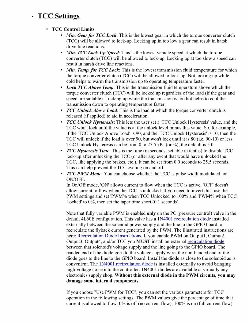
• TCC Settings
• TCC Control Limits • Min. Gear for TCC Lock: This is the lowest gear in which the torque converter clutch
(TCC) will be allowed to lock-up. Locking up in too low a gear can result in harsh drive line reactions.
• Min. TCC Lock-Up Speed: This is the lowest vehicle speed at which the torque converter clutch (TCC) will be allowed to lock-up. Locking up at too slow a speed can result in harsh drive line reactions.
• Min. Temp. for TCC Lock: This is the lowest transmission fluid temperature for whichthe torque converter clutch (TCC) will be allowed to lock-up. Not locking up while cold helps to warm the transmission up to operating temperature faster.
• Lock TCC Above Temp: This is the transmission fluid temperature above which the torque converter clutch (TCC) will be locked up regardless of the load (if the gear and speed are suitable). Locking up while the transmission is too hot helps to cool the transmission down to operating temperature faster.
• TCC Unlock Above Load: This is the load at which the torque converter clutch is released (if applied) to aid in acceleration.
• TCC Unlock Hysteresis: This lets the user set a 'TCC Unlock Hysteresis' value, and theTCC won't lock until the value is at the unlock level minus this value. So, for example, if the 'TCC Unlock Above Load' is 90, and the 'TCC Unlock Hysteresis' is 10, then the TCC will unlock if the load is over 90, but won't lock until it is 80 (i.e. 90-10) or less. TCC Unlock Hysteresis can be from 0 to 25.5 kPa (or %), the default is 5.0.
• TCC Hysteresis Time: This is the time (in seconds, settable in tenths) to disable TCC lock-up after unlocking the TCC (or after any event that would have unlocked the TCC, like applying the brakes, etc.). It can be set from 0.0 seconds to 25.5 seconds. This can help prevent the TCC cycling on and off.
• TCC PWM Mode: You can choose whether the TCC is pulse width modulated, or ON/OFF.In On/Off mode, 'ON' allows current to flow when the TCC is active, 'OFF' doesn't allow current to flow when the TCC is unlocked. If you need to invert this, use the PWM settings and set 'PWM% when TCC Unlocked' to 100% and 'PWM% when TCCLocked' to 0%, then set the taper time short (0.1 seconds).
Note that fully variable PWM is enabled only on the PC (pressure control) valve in the default 4L60E configuration. This valve has a 1N4001 recirculation diode installed externally between the solenoid power supply and the line to the GPIO board to recirculate the flyback current generated by the PWM. The illustrated instructions are here: Recirculation Diode Instructions. If you enable PWM on Output1, Output2, Output3, Output4, and/or TCC you MUST install an external recirculation diode between that solenoid's voltage supply and the line going to the GPIO board. The banded end of the diode goes to the voltage supply wire, the non-banded end of the diode goes to the line to the GPIO board. Install the diode as close to the solenoid as is convenient. The 1N4001 recirculation diode is installed externally to avoid bringing high-voltage noise into the controller. 1N4001 diodes are available at virtually any electronics supply shop. Without this external diode in the PWM circuits, you may damage some internal components.
If you choose "Use PWM for TCC", you can set the various parameters for TCC operation in the following settings. The PWM values give the percentage of time that current is allowed to flow. 0% is off (no current flow), 100% is on (full current flow).

For example, 70% means that the current is allowed to flow 70% of the time, simulating 70%×12V = 8.4 Volts on a 12V solenoid. The default for this setting is 'on/off'.
Full Time Lock Up: These settings allow you to lock the TCC at all times above a specified rpm and gear. This can be used to make the transmission more responsive, and also to boost top speed by locking the converter and gaining a few mph.
• At or Above RPM: This is the rpm to lock (and stay locked) at, regardless of the load. • Unlock At RPM: The full-time mode will be canceled and the TCC unlocked if the
engine rpm falls below the value specified here. This should be set at least a few hundred rpm below the 'At or Above RPM' to prevent the converter from cycling on and off when Full Time Lock Up mode is initiated.
• At or Above Gear: This is the minimum gear to use full time lock up. It must be at least 2nd gear. For top speed purposes, use the highest gear.
• TCC Upshift Settings
TCC individual upshift lock/unlock behavior is user configurable (under 'TCC Settings/TCC Upshift Settings'). You can set it to stay locked if it is already locked, or force it to unlock.
• Upshift to 2nd: Choose between: • Stay locked (if locked): If the converter is locked prior to the shift, allow it to
remain locked. • Unlock: Always unlock the converter (unless in full time TCC mode or jake
brake is active). • etc. ...
• TCC LOAD/PWM% Parameters
• TCC PWM Period: This is the period, in milliseconds, for the torque converter clutch control (TCC) solenoid pulse width modulation. You can enter a value between 0.427 and 10.888 (92 Hertz to 2340 Hertz) - the tuning software may round the value up or down slightly to be compatible with the processor's timer set-up. If your TCC specifies a value lower than this, usea multiple of that value. For example, if your OEM TCC uses 32 Hertz, you would specify 3×32 = 96 Hertz = 0.0104 seconds PWM period in the MShift™ controller.
• PWM% when TCC Unlocked: This is the pulse width modulation duty cycle desired when theTCC is not locked.
• PWM% when TCC Locked: This is the value that the TCC PWM percent will taper to, and it will stay at that level as long as the TCC is applied. The default is 100%.
Note: If you use PWM on the TCC circuit on a continuous basis (i.e. if either of 'PWM% whenTCC Unlocked' or 'PWM% when TCC Unlocked' does not equal 0% or 100%), you must put a1N4001 recirculation diode in the TCC solenoid. Install an external 1N4001 recirculation diode between that solenoid's voltage supply and the line going to the GPIO board. The illustrated instructions are here: Recirculation Diode Instructions. The banded end of the diodegoes to the voltage supply wire, the non-banded end of the diode goes to the line to the GPIO board. Install the diode as close to the solenoid as is convenient. The 1N4001 diode is installedexternally to avoid bringing high-voltage noise into the controller. 1N4001 diodes are available at virtually any electronics supply shop. Without this external diode in the PWM circuits, you may damage some internal components.
TCC lock-up start values: The following values set the PWM% that the TCC will start at, it will then move to the 'PWM% when TCC Locked' over the 'PWM Taper Time' you specify. This allows

you to have smooth engagement of the TCC Lock-up.
• Low Load Value: This is the load value (usually MAP in kPa) that is considered to be low load for TCC engagement PWM% purposes.
• PWM% at Low Load: This is the desired initial pulse width modulation duty cycle percent at low load (above). If this value is not 0% or 100% you will need a flyback 1N4001 recirculation diode on the TCC wires (see above).
• High Load Value: This is the load value (usually MAP in kPa) that is considered to be high load.
• PWM% at High Load: This is the desired initial pulse width modulation duty cycle percent at high load (above). If this value is not 0% or 100% you will need a flyback recirculation diode on the TCC wires (see above).
• PWM Taper Time: This is the desired amount of time (in seconds) over which the LUF should go from the load determined value (from the values above, as shown in the diagrams) to the 'PWM% when TCC Locked' value.
• Tables
Note: DO NOT power off the MShift™/GPIO board while the 'Flash Burn' indicator is active. Doing so *will* corrupt your settings. Wait a second or two for the burn to complete before powering down the board.

• Gear Auto-Shift Tables: These tables set the desired gear in auto mode.
Table switching is done with with the 2WD/4WD input on Ampseal pin 5 (GPI1/PE1). Table 1 is used if the pin is 'open' (voltage > 3.25V); table 2 is used if the input is grounded (low voltage).
Note: This code allows the use of processor pin PE0 for table switching whenever the 2WD/4WD input is used as an additional digital lever input. PE0 will have to be wired through an unused circuit and Ampseal pin with a 5V pull-up (an 1K resistor). Grounding thatpin will switching the the target gear control from table 1 to table 2. PE0 can be accessed from the 25x2 header on a GPIO board. It will need a 5V pull-up through a 1K Ohm resistor (and a 1K Ohm resistor can be put in-line between the pull-up and the processor pin). Pin PE0 is not brought out on the microTCU controller, so it cannot be used for table switching with the microTCU controller.
The shift table entries indicate the upshift gear that should be selected at the speed and MAP for that column and row.
For example, if the engine kPa is 60 kPa, and there is a 2 in the 40 mph bin and a 3 in the 50 mph bin, the transmission will shift from 2nd gear to 3rd gear at 50 mph (if the hysteresis conditions and rev limits are met). The transmission will downshift from 3rd to 2nd when decelerating at 49.9 mph at the same load, once the applicable hysteresis conditions are met.
Here is a calculator to help you decide on the before and after engine rpms when setting up thetable:
Gear RatioMPH
at specified enginespeed
RPMafter upshift
1
2
3
4
5 ---
Reverse---
Tire Section Width Tire Aspect Rim Size (in):

(mm): Ratio (%):
Engine Speed (rpm): Rear axle ratio: Desired SpeedoPulse/mile:
Computed Tirediameter (inches):
Output ShaftTeeth:
VSS Pulses per Mile:
Resulting VSS to Speedo Output ratio: (See this for more info.)
Note that you can use any reasonable rpm as the 'Engine Speed', it doesn't have to be the redline. So you could put in 2500 rpm, for example, and see if the rpm would drop too low after any of the shifts.
• Pressure Control Table: This table sets the transmission line pressure using the pressure control solenoid. The values are 40% to 100%. 40% specifies the minimum line pressure, 100% specifies maximum line pressure. These values are translated into the pressure control duty cycle as: PC duty cycle = 100-table_value (because the pressure control valve is typicallya normally closed 'bleed' mechanism, with maximum pressure at 0% duty cycle, and minimumpressure at 60% duty cycle). The table sets the pressure in gear, and sets the line pressure during shifts if the PC duty cycle from the table is lower than the maximum shift pressure setting.
• Bins
• Edit MAP Bins: This allows the user to set the load bins for the line pressure control and shiftcontrol tables to match the engine, vehicle and load sensor characteristics.
• Edit Speed Bins: This allows you to alter the vehicle speed bins for the shift control and line pressure control tables to suit your application. the maximum speed allowed is 255 mph/kph.
• Edit Temperature Bins: This allows the user to change the temperature bins for the line pressure temperature adjustments.
• LED Patterns
Reset

Note: DO NOT power off the MShift™/GPIO board while the 'Flash Burn' indicator is active. Doing so *will* corrupt your settings. Wait a second or two for the burn to complete before powering down the board.
Here you can set the LED patterns in each gear. The default is:
However, using these menu items, you can change the pattern in each gear. Select the gear you wish the change the pattern for from the menu, then change the pattern in the dialogue to have each LED "off" or "ON" for that gear.
For example, you can have only one LED light in each gear. You can also set two patterns for reverse:the LEDs will cycle through the set patterns once per second - allowing you to have the display flash in reverse as a warning.
Or if you wish to use a 7-segment LED to display the current gear numerically, you can use these pattern to adjust the 4 LED outputs to be suitable for a 7-segment LED driver (such as the 4511 7-segment decoder/display driver IC).
Note that when driving LEDs, "ON" means current is allowed to flow, and "off" means current is not allowed to flow. If you are using a pull-up circuit with a 7-segment LED driver IC, "ON" will mean the pull-up voltage is held low (< 0.7 Volts), while "off" will mean the pull up voltage is high. So it might be backwards to what you expect (unless you are using the processor pins directly, in which

case "ON" means 5V is being supplied).
There is much more on using the 7 segment LED/LCD driver here: 7segment.html
• Tuning
• Gear Shift Tables: This are two 16x9 table that indicates the target gear in auto mode by speed and load. It is up to the user to make sure these gears are appropriate, and will not over-rev the engine, etc. Enabling RPM checking is highly recommended until the shift speeds are confirmed.
• Pressure Control Table: This is a 16x9 line pressure table. An entry of 100% represents maximal line pressure, 40% is minimal line pressure. (This is 'backwards' compared to the pressure control solenoid's PWM duty cycle, since the line pressure solenoid is usually a bleed valve, and 0% represents 'no bleed' = max. pressure. TunerStudioMS 'inverts' the valuesto the more intuitive 100% = max. pressure, 40% = minimum pressure by sending the controller the value 100 - table value.)
• Speedometer Correction: This is a 16 element table (with its own speed bins) of adjustments to the measured 'raw' speedometer from the VSS to adjust the reported speed to account for noise in the VSS signal, tire growth, tire slippage, etc. The corrected speedometer values are used in the code for all purposes - shifting, spare port conditions, line pressure control, etc. Raw speedometer values are used only for deriving the corrected values. The correction valuescan be up to ±100%.
• Line Pressure v. Temp.: This is the line pressure control PWM percent adjustment over 10 temperatures. It is meant to adjust for the changed viscosity of the trans fluid, as well as for different electromechanical response of the pressure control solenoid at different temperatures.
• Spare Port X (index) This gives a graph of the the 12x1 spare port X index versus PWM%, along with the associate tables, all in one place. Note that the index bin values must not be negative.
• Spare Ports
Note: DO NOT power off the MShift™/GPIO board while the 'Flash Burn' indicator is active. Doing so *will* corrupt your settings. Wait a second or two for the burn to complete before powering down the board.
Spare Port Function: The function of each three 'spare ports' can be selected under: Spare Ports→Spare Ports Function→Spare Port X Usage (there are 5 modes, corresponding to 5 values of the parameter spX_mode):
• User Spare Ports/Speedo Output*:
• Spare Port 0 Use: For spare port 0 (but not spare port 1 or spare port 2), the user can select to enable this output to send a signal to an electronic speedometer. The output will then put out a pulse/mile signal (based on the VSS input) of the user's choice. To set this up, set the function to 'Speedo Output' under 'Spare Ports→Spare Port Function'and then set the desired pulse/mile under 'Spare Port→Speedo Output on Spare Port 0':
• Output pulse/mile: This is the output pulses/ mile (or pulses/kilometer if you

have set Metric units) for the speedometer output. The output is triggered in the VSS tooth interrupt (not the main loop), and has to be at least 2 of these long (one tooth to turn on, next tooth to turn off, etc.). As long as the ratio of speedometer output to VSS input is reasonable (say 1:5 or 'higher') it will work fine. Typically, the VSS gives about 96000 pulses per mile and the speedometerwill require 2000 to 4000 pulse/mile. This is a VSS/speedo pulse ratio of 24:1 to 48:1; well within the range needed to work effectively with your MShift™/GPIO controller. This output is used to drive an electronic speedometer (such as those found on many newer vehicles) - it is adjusted automatically when you change the VSS settings (such as tire diameter, rear axle ratio, etc.). The output is a 0-12V square wave.
The speedometer output signal will adjust automatically after a reset when you change the tire size, final drive ratio, or number of VSS teeth. If not used as a speedo output, this is a PWM enabled port with a 16x9 lookup table.
You can use the calculator above to determine the ratio of the VSS input frequency (pulse/mile) to the speedo desired output.
• Speedo Output Duty Cycle: You can use this parameter to set the pulse width modulation percentage for the speedometer output signal. It can be set from 1% to 99%, where the percentage is the time 'high' when the signal from the processor is used to control a PNP transistor with a pull-up circuit (i.e. the standard build). This can help in making the speedo output signal compatible with some speedometers. The default is 50%.
• Spare Port 1 Use: For Spare port 1 and spare port 2 (but not spare port 0), the user canselect settings to control the behavior based on speed, rpm, load. ON and OFF PWM percentages are based on the 12 element table (ON) and PWM OFF value (OFF). The PWM is updated continuously based on the index value. The AND'ed conditions, thresholds, and hysteresis values are set under: Spare Ports→User Spare Port X.
There are two 'user spare ports' (SP1/SP2) that are an ANDed combination of speed, rpm, load, and current gear (with hysteresis). Assuming they are not used for another function (like a 4th shift solenoid), these can be used to control external devices like fans (ex. shut off above a specified speed), or ancillary trans functions.
These are the 4 conditions on 4 variables (vehicle speed, engine rpm, load, and current gear) that can be used to set the state of the spare port output on Ampseal pin 11. The conditions are:
• 'no condition': this is ignored, so if you don't want to use 4 conditions, you don't have to. Just leave the unwanted variables as 'no condition'.
• 'greater than or equal to' • 'less than or equal to'
Note that the port is not directly aligned with the circuit on the 25x2 header. To use spare port 1, you must jumper from PT7 to VB1 (they are near opposite corners of the 25x2 header).
For example, if you set: • condition to 'greater than or equal to', • speed to 50, and • hysteresis to 5

and have 'no condition' on the remaining variables, then Output1 will go high when the speed reaches 50 (either mph or kph depending on what you have your units set to), and won't go low until the speed drops below 45.
• Spare Port 2 Use:
You can set up to 4 of the following conditions. There are 4 conditions on 4 variables (vehicle speed, engine rpm, load, and current gear) that can be used to set the state of the spare port output on Ampseal pin 12. ALL must be 'true' for the output to switch. The conditions are:
• 'no condition': this is ignored, so if you don't want to use 4 conditions, you don't have to. Just leave the unwanted variables as 'no condition'.
• 'greater than or equal to' • 'less than or equal to'
Note that the port is directly aligned with the circuit on the 25x2 header. To use spare port 2, you just jumper from PA0 to VB2.
For example, if you set: • condition to 'less than or equal to', • speed to 50, and • hysteresis to 5
and have 'no condition' on the remaining variables, then Output2 will go high until the speed reaches 50 (either mph or kph depending on what you have your units set to), and will stay low until the speed drops below 45.
• PWM mode: For spare port 0: Use the only PWM 144 (16x9) element table and OFF value to set the state. This setting relies on the 'PWM active' parameter (below) to determine when the PWM state is ON or OFF. The PWM can be set to a range of values from 0% to 100% in 144 bins (and the user can select if the interpolated PWM percent varies with load, temperature, speed, or engine rpm. The user can also set a single separate OFF value for the PWM. If the user doesn't want varying PWM, and wants and ON/OFF output instead, they can simply set all the table values to 100% and the OFF value to 0% (or vice-versa).
For spare port 1 and spare port 2: Use the only PWM 12 element table and OFF value to set the state. This setting relies on the 'PWM active' parameter (below) to determine when the PWM state is ON or OFF. The PWM can be set to a range of values from 0% to 100% in 12 bins (and the user can select if the interpolated PWM percent varies with load, temperature, speed, or engine rpm. The user can also set a single separate OFF value for the PWM. If the user doesn't want varying PWM, and wants and ON/OFF output instead, they can simply set all the table values to 100% and the OFF value to 0% (or vice-versa).
Spare Ports→Spare Port X PWM Setup→PWM Active (spX_active): • PWM Active: In PWM mode, the user has 3 choices as to when the PWM table is
used: • always ON: PWM percent is always based on the 12 element table, whether
shifting or not. The OFF value is not used. • ON except while shifting: PWM percent is based on 12 element table, except
during shifting when it is set to the user specified OFF value. • ON only during shift*: PWM percent is based on 12 element table during
shifting, but when not shifting the PWM percent is set to the user specified OFFvalue. (This is the inverse of the previous mode.)
* = default value; X = 0,1,2

• PWM Index: The pulse width modulation uses a table lookup for the ON state and hasan OFF value as well as index options. For spare port 1 and 2, the user can select the index value to use ('Spare Ports→Spare Port X PWM Setup→PWM Index') to interpolate the 12 element PWM% table based on the bins in the 'Spare Ports→Spare Port X PWM Index' table. For spare port 0, the user can select the index values to use ('Spare Ports→Spare Port X PWM Setup→PWM Index') to interpolate the 144 element PWM% 2-D table based on the bins in the 'Spare Ports→Spare Port X PWM Index' table. The possible index values are:
• Load*, • Speed, • RPM, • Temperature (only positive temperatures are allowed).
* = default value; X = 0,1,2
• PWM Period: This is the period of the pulse width modulation. The period = 1/frequency. The PWM clock operates in 0.128 millisecond 'ticks'. The period can be from 30.6 Hertz (cycles per second) to 1953 Hertz. You can enter any value you like, but the tuning software will round this to a multiple of 0.128 milliseconds.
• PWM% when inactive: This is the desired PWM percentage when the spare port is in the OFF state. It can be set to 0 (actually off), or any other value up to 100% (it will be rounded as necessary).
For spare port 1 and 2 there are two 12x1 tables for each spare port's PWM. One (Spare Port XPWM Percent) sets the percentage of 'ON-time' for each bin of the index table. The index tableis used to compare the current 'PWM Index' value (which can be the current load, speed, temperature or rpm, depending on what you have selected in the PWM setup) to the index bin values. The code finds the closest bin values in the index table, and then computes the interpolated PWM% from the 'PWM percent' table. Dealing with two separate table is awkward, though. Instead, it may be easier to use the 'Tuning→Spare Port X (index)' graphicalpresentation. This gives a graph of the index versus PWM%, along with the associate tables, all in one place.
For spare port 0 there are two index table (a 9 element bin table for the y axis, and a 16 element bin table for the x axis). These are used to interpolate the PWM percentage from a 144 element table. The bin values and PWM table can be edited under 'Tables→Spare Port 0 Table' once the spare port 0 is set to a PWM enabled usage under 'Spare Ports→Spare Port Function→Spare Port 0 Use' (i.e. if it is not set to be a speedo output).
Note that the PWM reported in TunerStudio is the actual PWM percentage. As the frequency increases, the 'granularity' of the possible PWM% increases, and the PWM% may be off from the target by up to several percent. Lowering the PWM frequency (increasing the period) will result in better accuracy.
• TCC mode: Output is ON (PWM% from 12x1 table for sp1/2, from the 16x9 table for sp0) while TCC is engaged, OFF otherwise. None of the spare port TCC settings affect the main TCC output on PT3 (which has its own PWM frequency, PWM algorithm, etc.)
• Use as Shift Solenoid: Output state is changed at some shifts based on user's output pattern. PWM% from 12x1 table in ON state. Note that if you want to have a constant PWM% for the shift solenoid, you should enter that value in all 12 bins (sp1 & sp2) or 144 (sp0) of the spare output's PWM % table.

• Selective Clutch: This parameter is to select using as ports active only during shifts (i.e. 'clutch' outputs), which are active only during the shifts specified under 'Shift Output Patterns→Clutch Pattern (Output 4/7)'. The ON state PWM percent is set by the 12x1 table forspare port 1 and spare port 2. The ON state PWM percent is set by the 16x9 table for spare port 0.
• Communications
Note: DO NOT power off the MShift™/GPIO board while the 'Flash Burn' indicator is active. Doing so *will* corrupt your settings. Wait a second or two for the burn to complete before powering down the board.
• Settings: • Configuration: This is the project name from which the initial communications
settings have been taken. • Port The communications port number should correspond to the port to which the MS
controller is attached. Usually you will select port 1 or 2, but some machines force you up to higher numbers (for instance, we have seen COM5 as the default on some IBM Thinkpad laptops). If you are using a USB/serial adapter, it may be as high as COM8 or COM9, or even higher. You can either look in the Control Panel under System/Device Manager, or simply try each COM port until you get a connection.
• Baud Rate The data rate is hard coded into your MegaSquirt® embedded code, use: 115200 for MegaSquirt-II™. Other values will NOT work without re-coding and reprogramming and you will spend a lot of time trying to figure out what is wrong.
• Test Port: Click this button to attempt serial communications with the controller. Success will be reported if TunerStudioMS is able to contact your MegaSquirt® controller over the controller automotive network (CANbus).
• Data rate: Select the data rate (in output channel reads per second) you would like to use on your serial connection. You have choices from 1 per second to maximum per second. Some options may be grayed out if your hardware doesn't support that speed,. you may need to choose a lower speed for some serial connections (such as a USB/serial converter or Bluetoothconnection).
• Mini-Terminal:This is an 'internal' version of hyperterminal for low level communications with MShift™ for troubleshooting, etc.
• Diagnostic Log Comm: This creates a detailed communications log for troubleshooting CANbus and serial communication issues. It is *NOT* the normal datalog of MShift™ variables.
• Tools
Note: DO NOT power off the MShift™/GPIO board while the 'Flash Burn' indicator is active. Doing so *will* corrupt your settings. Wait a second or two for the burn to complete before powering down the board.
• Binary Log Viewer: This utility will let you open a raw binary log file and view it in a number of formats.

• Expression Evaluator: This utility will let you design mathematical expressions using number, math operators, and the output channel variables and give you the value based on the current inputs. It can be very helpful for designing new variables to put into the INI.
• Calibrate TPS: This will allow you to calibrate the throttle position sensor from the 1024 ADC counts that the MShift™ controller uses to the 0-100% that TunerStudioMS uses.
To calibrate the throttle: • Shut the engine off and leave it off until the procedure is complete. • Take your foot completely off the accelerator pedal, and click on the 'Get Current'
button beside the 'Closed Throttle ADC Count' value. • Press the throttle pedal all the way down, and click on the 'Get Current' button beside
the 'Full ADC Count' value. • Click the 'Close' button and you are done.
Note that you may have to re-calibrate if you have changed the idle stop using the throttle stopscrew.
• Calibrate Thermistor Table: This calibrates the thermistor (for the transmission fluid temperature) based on the bias resistor value and three temperature/resistance pairs (usually freezing, boiling, and room temperature - but if you have a source that gives values from a table for your sensor, choose one in the middle and the others from each end of the table).
Note that the transmission fluid temperature values are stored as 'Coolant Temperature Sensor'in TunerStudio. Do not recalibrate the Air Temperature Sensor table.
• CANbus Configuration:
The CANbus user parameters in the MShift™ code are:
• CANbus Usage: Choose whether to use CANbus or not. If not using CANbus, then an alternate LOAD signal must be used; see: ISS/non-CANbus Tach Settings.
• CANbus ID (GPIO): This is the CANbus ID for the GPIO board running MShift™. The default is 1. You can change the CANbus ID in the menus to a value up to 13 to avoid conflicts with other CANbus devices - if you do change the MShift™ CANbus ID you must also change it in the tuning software under 'File/Project Properties/CAN Devices'.
• CANbus Fetch Rate: This is the number of 0.128 millisecond tics between CANbus requests to send outpc. variables over from MS-II.
• CANbus Load Variable: Choose to use the TPS or the MAP signal as the load signal over CANbus from the engine controller. The choices are:
• MAP • TPS • TPS for Line Pressure Table/MAP for Gear Tables • MAP for Line Pressure Table/TPS for Gear Tables
If you choose mixed loads (3 or 4 above), you also need to activate/deactivate some settings under Project -> Project Properties:

• if you are using TPS for Line Pressure Table/MAP for Gear Tables you should make sure:
1. GEARTABLEMAP is activated, and 2. PCTABLEMAP is deactivated
• if you are using MAP for Line Pressure Table/TPS for Gear Tables you should make sure:
1. GEARTABLEMAP is deactivated, and 2. PCTABLEMAP is activated
These will set the appropriate displays (the load axis index and bins) for the tables in TunerStudio.
If you are using only MAP or only TPS (either of the first two options) you only need to make sure LOAD_KPA is activated (for MAP) or deactivated (for TPS).
Also, note that the usual hysteresis limiting applies, except when MAP for Line Pressure Table/TPS for Gear Tables, in which case there is hysteresis on the speed, but not the TPS (this can block shifts on the stim, but with reasonable hysteresis values isn't likely to in real life).
• MS-II CANbus ID: Set the CANbus ID of the primary ECU (the one you will connectthe serial cable to). This is always 0 for MS-II/MS-II Sequencer.
• MS-II outpc block: This is the block number of the outpc structure on an MS-II™ or MicroSquirt® controller (which contains all the dataloggable variables, including the pw1, tps, map, vBatt, and kpa variables used by the MShift™ controller). This is normally 7 for the standard code. You can derive this value from the INI by looking in the [OutputChannels] section, and find a line like:
ochGetCommand = "a\x00\x06" ; Lower case so we don't get confused.
The last value for the 'output channel get command' (ochGetCommand) is x06, which indicates the hexadecimal count for the txtbuf table used for serial communications. The tables in B&G's 2.905 code are:
• cltfactor_table - the ADC count to temperature table for CLT, • matfactor_table - the ADC count to temperature table for IAT, • egofactor_table - the ADC count to AFR table for WBO2, • maffactor_table - the ADC count to air flow table for MAF, • inpram - the first page of input parameters, • in2ram - the second page of input parameters, • txbuf - the bufferred output channel values, • outpc - the unbufferred output channel values.
The text buffer for the outpc table is at table 0x06. The text buffer is isolated from the values as they change, so is less likely to produce errors on 'non-atomic' multi-byte word values. But the actual outpc for CANbus use is at table 7. So use either of the values 6 or 7 for the MS-II™/MicroSquirt® outpc table.
txbuf (table 6) has the same structure and 99.9% of the time has the same content as outpc, and when it doesn't, txbuf is more likely correct. That's why it exists and why TunerStudioMS uses it.

• VSS offset: This code can take a VSS signal over CANbus. When it does this, it ignores any VSS signal sent directly to the GPIO's VSS input pin (eventually we will make that input available for other uses).
To use the CANbus VSS, you need to specify the offset of the VSS value in the outpc. structure. You do this under 'Tools -> CAN Configuration -> VSS offset'. If you set thevalue to zero (the default), or the CANbus is not enabled, the GPIO's VSS input is used. If it is not set to zero and CAN is enabled, the VSS from the external CANbus controller is used.
You can determine the required offset from the outpc. structure. The outpc structure is described in the [OutputChannels] section of the INI for your code. This will look something like:
[OutputChannels]
deadValue = { 0 }; Convenient unchanging value.
ochBlockSize = 112
ochGetCommand = "a\x00\x06"; Lower case so we don't get confused.
seconds = scalar, U16, 0, "s", 1.000, 0.0
secl= { seconds % 256 },
"s"; For runtime screen.
pulseWidth1 = scalar, U16, 2, "s", 0.001, 0.0
pulseWidth2 = scalar, U16, 4, "s", 0.001, 0.0
...
VSS = scalar, U16, %%, "mph", 0.100, 0.0
...
where the number in the "%%" position is the value you need to enter for the 'VSS offset'. The speed value may have a different label (i.e. "speed" or "speedo" or "mph", etc., instead of "VSS"; that doesn't matter). However, the speed must be x10 (0.100 in the line above), and it must be an unsigned integer (U16 above).
• Outpc CANbus message format: This allows the user to select between:

• using the outmsg protocol ('Get only required vars'), or • grabbing the entire outpc ('Get all vars').
Grabbing only the required variables (10 bytes) is faster and more efficient. Grabbing the entire outpc (112 bytes) is necessary if the MS-II/MicroSquirt code doesn't have a compatible outmsg format. MS-II™ 2.90X code and 2.003+ MShift™ code have compatible outmsg's as defaults. TunerStudio has a utility to burn new outmsg formats to other code versions, but this is not tested yet.
• Spark/Fuel/Idle Adjustments: The following give the location in MS-II's memory of the fuel, spark and idle adjustments (that are sent from MShift™). Normally you won't change these location parameters, unless the code on MS-II is 'non-standard'.
• MS-II in2ram block: The table number (from the tableDescriptor fields) of the MS-II™/MicroSquirt® table containing the external adjustment variables from MShift™. The default is 5 (which is the 3.770+ & 2.905+ code's in2ram table). You can derive this value from the INI by looking in the [Constants] section, and find a line like:
pageIdentifier = "\x00\x04", "\x00\x05"
There are two sets of values in this case, for inpram (=x04) and in2ram (=x05) (other codes may have more or less sets). The last value in the last set, x05 indicates the hexadecimal count for the in2ram table that contains the adjustments in the case of this code (but not necessarily all codes). So use the value 5 for the in2ram block that contains the adjustment variables for MS-II™ or MicroSquirt® controllers using code from B&G.
• MS-II variable offset: The adjustment variables offset on the engine controller from the start of the 'MS-II in2ram block' table. The default is 946.
The code will write the adjustments in the table, starting at the offset entered. It will write eight (8) bytes:
1. Fuel adjustment - 2 bytes (default is table 5, offset 946 & 947), 2. Spark adjustment - 2 bytes (default is table 5, offset 948 & 949), 3. IAC adjustment - 2 bytes (default is table 5, offset 950 & 951), 4. spare adjustment - 2 bytes (default is table 5, offset 952 & 953) - unused
as of the 2.000 code but still must be available in the engine controller code or the value there will be overwritten.
Note that these values are also used in MicroSquirt® controllers, the Sequencer™ controllers, etc.
So the controller for the engine must have 8 bytes set aside (in the order above) in the chosen table for it to read and implement these adjustments. They do not have to have these specific names, however. All B&G code since 2.901/3.430 has these bytes reserved as in2ram bytes 946 - 953 (you will find these in 'page 2' of the INI's [Constants] section). Other codes may or may not have this already implemented - check with your code's developer.

MShift™, CANbus, and MS/Extra Code
MS3/Extra: Please check at the www.msextra.com forumsto get the adjustment variable names, offsets, etc. Because the relevant values appear to move from one version to another in the ms3/extra code, you best bet if you are running ms3/extra is to ask about these offsets for the particular code you are using on the www.msextra.com forums.
In theory, you should be able to find the values in the INI using the example above, once you know the relevant variable names.
For example, in the pre-release ms3/extra code, these were the same as the defaults above. However, we have been informed that the release code has in2ram at table 7, with the relevant variables starting at offset 630. We don't knowwhat the outpc table number is (it can't be 7, since that is apparently taken by in2ram), but a look in the INI for your code should reveal all of these values.
MS2/Extra: Apparently MS2/Extra code versions after November 20, 2010 had the appropriate parameters inserted. These were located at block = 7, offset = 622. So set:
• MS-II outpc block = ?
• MS-II in2ram block = 7 • MS-II variable offset = 622
These are NOT the same as the defaults, so you willneed to edit some of the values.To make these values 'editable', see below.
The developers of extra code may change these values in newer releasers of the code, so you shouldcheck on the msextra forums for up-to-date information.

Check with the developers at www.msextra.com to verify these values.
All of the CANbus parameters can be changed in the tuning software. However,by default some are blocked by the INI configuration to prevent users from accidentally disabling their CANbus communications. To enable editing of one or more of these parameters, you must find the line in the INI for that parameter(around line 1246), and change the last section of the line where it says { 0 } to { 1 } to make editable in the tuning software. You can do this using notepad.exe(which comes with Windows and which can be found under 'Start/All Programs/Accessories/Notepad'), or you can use any general text editor.
dialog = canconfig, "CANbus Configuration"
topicHelp = "http://www.msgpio.com/manuals/mshift/V2tune.html#oa"
field = "#Controller Area Network set-up"
field = "!CANbus Usage", CAN_enabled
field = "!CANbus ID (GPIO)", trans_can_id, { CAN_enabled }
field = "!CANbus Fetch Rate", can_var_rate, { CAN_enabled }
field = "CANbus Load Variable", load_type, { CAN_enabled }
; field = "!Board Type", board_type, { CAN_enabled }
field = "!MS-II CAN ID", ms2canID, { 0 } ; change to { 1 } to make editable
field = "!MS-II outpc block", ms2varBLK, { 0 } ; change to { 1 } to make editable
field = "!Outpc CANbus message format", can_testout, { CAN_enabled }
field = "Spark/Fuel/Idle Adjustments"
field = "!MS-II in2ram block", Adj_blk, { 0 } ; change to { 1 } to make editable
field = "!MS-II variable offset", Adj_varoffset, { 0 } ; change to { 1 } to make editable
field = ""
field = "If CANbus is disabled, load is determined"
field = "from 0-5V auxiliary input on AMP pin 24"
field = "See 'General Settings/Non-CAN Load Settings'"
The file you edit will be in the TunerStudio project folder (something like: C:\Users\user\Documents\TunerStudioProjects\project name\projectCfg\). The default file names for the files you need to edit will be either:
5. mainController.ini if you are connecting the serial connection directly to the GPIO board, or
6. CAN1.ini if you are using the CANbus pass-through and connecting theserial cable to MS-II.
If you cannot find a file with one of these names, try a file with the .ini extension in the /projectCfg/ folder.

For more CANbus configuration information, including wiring and tuning software setup, see: www.msgpio.com/manuals/mshift/cpt.html
• Help
• MegaShift™/GPIO Info: • Burning Values to ECU:
1 'Bit banging' means the port is turned off and on by specific instructions in the code that occur within normal program flow. In MShift™ the chance to turn these outputs off and on occurs every 1/8th of a millisecond. The alternative is to use timer channels. These are built in processor hardwaredevices that allows the user to set the PWM frequency and duty cycle, and the hardware handles the PWM switching independently of the program code. This not only reduces computational overhead, but can be switched an much higher (or lower speeds) and is also is much more accurate.
MegaSquirt® and MicroSquirt® controllers are experimental devices intended for educationalpurposes.
MegaSquirt® and MicroSquirt® controllers are not for sale or use on pollution controlled vehicles.Check the laws that apply in your locality to determine if using a MegaSquirt® or MicroSquirt®
controller is legal for your application.
© 2011, 2014 Bruce Bowling and Al Grippo. All rights reserved.