meeting of the technical committee on hazardous …
TRANSCRIPT

MEETING OF THE
TECHNICAL COMMITTEE ON HAZARDOUS MATERIALS
PROTECTIVE CLOTHING AND EQUIPMENT
March 15-17, 2011
Embassy Suites Galleria, Atlanta, GA
AGENDA
Tuesday, March 15 (continuing through close of business on Thursday, March 17, but NLT 5:00 p.m.)
1. 10:00 a.m. Call to Order
2. Introduction of Members and Guests
3. Committee Procedures, Staff Liaison Dave Trebisacci
4. Approval of the Minutes of the May 17-18, 2010 ROP meeting, Baltimore, MD
5. Chair remarks
6. Public Comments and TC Comments to NFPA 1991, NFPA 1992 and NFPA 1994
Please note - any public comments received via the NFPA comment submission process will be sent to the TC immediately following the comment closing date of March 3, 2011. Any technical committee comments received by NFPA staff as of March 1, 2011 will also be forwarded to the TC.
7. Task group reports
8. Update on SCAM work project
9. Old Business
10. New Business –
Select dates and recommend locations for future TC meetings
11. Adjourn at close of business, but NLT 5:00 p.m. on Thursday, March 17, 2011.

Report on Comments – November 2011 NFPA 1991_______________________________________________________________________________________________1991- Log #31 FAE-HAZ
_______________________________________________________________________________________________Jeffrey O. Stull, International Personnel Protection, Inc.
1991-8Revise text to read as follows:
1.3.6* Requirements of this standard shall not apply to the use of closed circuit SCBA.A.1.3.6 The testing in this standard is currently limited to an NFPA 1981 compliant open circuit SCBA.4.3.18 The manufacturer shall be permitted to specify one or more different types of specific self-contained breathing
apparatus for use with the vapor-protective ensemble. Where the manufacturer submits a vapor-protective ensemble forcertification with one or more specific self-contained breathing apparatus, the certification organization will require themanufacturer to list the acceptable self-contained breathing apparatus as part of the product label as specified in5.1.1.11 and require overall ensemble function and integrity testing using each listed self-contained breathing apparatusas specified in Section 8.4.5.1.1.11 Where specific self-contained breathing apparatus are specified by the manufacturer for the certification of the
vapor-protective ensemble, the following additional statement shall be provided as part of the product label:FOR COMPLIANCE WITH NFPA 1991, THE FOLLOWING SELF-CONTAINED BREATHING APPARATUS MUST BE
USED IN CONJUNCTION WITH THIS VAPOR PROTECTIVE ENSEMBLE:(List each self-contained breathing apparatus).5.2.4(4)(d) Proper integration and wearing of ensemble with specified self-contained breathing apparatus, if applicable.5.2.2.2(12) Type of or specific self-contained breathing apparatus to be worn with vapor-protective ensemble.8.4.4.1(6) Unless otherwise specified, test subjects shall wear a self-contained breathing apparatus (SCBA) that is
compliant with NFPA 1981, Standard on Open-Circuit Self-Contained Breathing Apparatus for Fire and EmergencyServices.(7) Where specific self-contained breathing apparatus are specified by the manufacturer for the certification of the
vapor-protective ensemble, separate testing shall be performed with each type of self-contained breathing apparatusspecified by the manufacturer.8.8.4.11 For consistency in testing Unless otherwise specified, the SCBA used for all testing with the vapor-protective
ensemble shall be certified as compliant with NFPA 1981, Standard on Open-Circuit Self-Contained BreathingApparatus for Fire and Emergency Services, and shall be equipped with a fully charged 60-minute breathing air cylinder.8.4.4.12 Where specific self-contained breathing apparatus are specified by the manufacturer for the certification of the
vapor-protective ensemble, separate testing shall be performed with each type of self-contained breathing apparatusspecified by the manufacturer.
This requirement is design restrictive and will prohibit use of alternative SCBA that have frequentlybeen used as part of vapor-protective ensembles. It will also prevent the development of innovative designs involvingthe integration of SCBA with vapor-protective ensembles that could afford potential advantages for hazardous materialsfirst responders in terms of reduced weight, profile, and stress as well as increasing ensemble service life, whenneeded. The NFPA Technical Committee on Respiratory Protective Equipment is working on a new standard for closedcircuit self contained breathing apparatus that may become available sometime after the promulgation for the newedition of the NFPA 1991 standard. Specific changes to the standard have been proposed that permit certification andtesting with other types of SCBA, when specified by the manufacturer.
1Printed on 3/11/2011

Report on Comments – November 2011 NFPA 1991_______________________________________________________________________________________________1991- Log #8 FAE-HAZ
_______________________________________________________________________________________________Jeffrey O. Stull, International Personnel Protection, Inc.
1991-1Revise text to read as follows:
Add to 2.3.2: ASTM F 2700,2008.
Delete from 2.3.4: ISO 17492,2003
The test apparatus specified in ISO 17492,
shall beused.
Radiant protective performance testing shall be performed in accordance with ISO 17492, Clothingfor protection against heat and flame--determination of heat transmission on exposure to both flame and radiant heat,Standard Test Method for Unsteady-State Heat Transfer Evaluation of Flame Resistant Materials for Clothing withContinuous Heating, shall be used with the following modifications:(1) An exposure heat flux of 84 kW/m2 (2.0 cal/cm2s) shall be used.(2) (1) The contact configuration optional spacer shall not be used for testing of all material specimens.(3) (2) The thermal threshold index analysis method heat transfer performance value shall be used with calculations
made using the heat flux in calories per square centimeter per second and reported as the TPP rating.(4) T-150 quartz tubes shall be used.
The individual test TPP rating of each specimen shall be recorded and reported. The average TPP rating shallbe calculated, recorded, and reported.
Where a TPP rating is greater than 60, then the TPP rating shall be reported as "<60."The proposed reference test method for the conduct of thermal protective performance (TPP) has
been updated and includes an improved calibration protocol. The new method permit reporting of TPP values greaterthan 60 cal/cm2.
_______________________________________________________________________________________________1991- Log #3 FAE-HAZ
_______________________________________________________________________________________________Marcelo M. Hirschler, GBH International
1991-1Revise text to read as follows:
Radioactive particulates, including alpha and beta particulates,that are generated from a source of radioactive material or nuclear event which are intentionally used to inflict lethal orincapacitating casualties, generally on a civilian population as a result of a terrorist attack. The contaminated particlesemit ionizing radiation.
The contaminated particles emit ionizing radiation.The proposed definition conflicts with the Manual of Style as it has multiple sentences. The second
sentence is not part of the definition but is information that can be placed into an annex or somewhere in the body of thestandard.
2Printed on 3/11/2011
Report on Comments – November 2011 NFPA 1991_______________________________________________________________________________________________1991- Log #1 FAE-HAZ
_______________________________________________________________________________________________Marcelo M. Hirschler, GBH International
1991-1Revise text to read as follows:
Any component that allows the passage of gases, liquids, or electrical current from theoutside to the inside of the element or item as well as any . Any fitting externally located on, and part of, the ensemblewhich is not part of the garment material, visor material, gloves, footwear, seams, or closure assembly.
The proposed definition conflicts with the Manual of Style as it has multiple sentences. The secondsentence needs to be changed either by incorporating into a single sentence (as proposed) or by placing it elsewhere inthe standard.
_______________________________________________________________________________________________1991- Log #2 FAE-HAZ
_______________________________________________________________________________________________Marcelo M. Hirschler, GBH International
1991-1Revise text to read as follows:
A positive pressure, self-contained breathing apparatus (SCBA) or combinationSCBA/supplied-air breathing apparatus certified by the National Institute for Occupational Safety and Health (NIOSH)and certified as compliant with NFPA 1981,
.Certification of respiratory equipment. Respiratory equipment shall be certified by the National Institute for
Occupational Safety and Health (NIOSH) and shall be certified as compliant with NFPA 1981,.
The proposed definition conflicts with the Manual of Style as it contains requirements. The proposedchange will place the requirements where they belong, which is within the body of the standard.
_______________________________________________________________________________________________1991- Log #17 FAE-HAZ
_______________________________________________________________________________________________Daniel J. Gohlke, W. L. Gore and Associates
N/ARewrite 3.3.55 Sample. The ensemble, element, item, component, or composite that is conditional
prior to testing. (see also specimen).This is the definition of sample from NFPA 1951. It captures the important concept that samples are
the subject of conditioning which is not captured in the current definition.
_______________________________________________________________________________________________1991- Log #26 FAE-HAZ
_______________________________________________________________________________________________Technical Correlating Committee on Fire and Emergency Services Protective Clothing and Equipment,
1991-17The TCC instructs the Technical Committee on Hazardous Materials Protective Clothing and
Equipment to consider adding the text "During each inspection" to the beginning of the new Section 4.3.18. TheTCC recognizes that there will be a new Section 4.3.18 to follow the existing Section 4.3.17.
This is a direction from the Technical Correlating Committee on Hazardous Materials Protective
Clothing and Equipment in accordance with 3.4.2 and 3.4.3 of the Regulations Governing Committee Projects.
3Printed on 3/11/2011
Report on Comments – November 2011 NFPA 1991_______________________________________________________________________________________________1991- Log #5 FAE-HAZ
_______________________________________________________________________________________________Jeffrey O. Stull, International Personnel Protection, Inc.
1991-17Revise text to read as follows:
The certification organization shall ensure that the manufacturer tests each vapor protective suit element forgastight integrity as specified in Section 8.2, Gastight Ingetrity Test. Each suit element shall show an ending pressure ofat least 1350 Pa (5.4 in) 125 mm (5 in.) water gauge pressure. The date of the test shall be placed on the product labelas specified in Section 5.1.1.8(5). Additionally, the manufacturer shall provide the result with each suit.
I oppose the change for modifying the gas-tight integrity test specified in NFPA 1991 to the Europeanapproach for two primary reasons--(1) There are no data and no research has been conducted to justify that theproposed change in the test procedures will provide a higher degree of suit quality and integrity as used as the basis inaccepting this modification, and (2) The idea that the committee should have a goal of harmonization with theInternational standards on chemical protective clothing is absolutely preposterous.The basis for the current pressure test procedures can be found in the following reference:Carroll, T. R., Resha, C. J., Vencill, C. T., and Langley, J. D.,
Sixth Volume, Performanceof Protective Clothing: ASTM STP 1273, Jeffrey O. Stull and Arther D. Schwope, Eds., American Society for Testing andMaterials, 1997, pp. 3-15.This research evaluated a range of pressure testing conditions, including those used in Europe and Internationally.
Experiments were conducted to determine the relative sensitivity of the inflation pressure, dwell pressure, and dwell timein showing pressure drop from leaks introduced into sample garments from different diameter hypodermic needles. Atthe time of this research, a slightly lower inflation pressure (3 in.), dwell pressure (2 in.) and test duration (3 minutes)were specified in the procedures of ASTM Test Method F1052. These conditions, along with those established in EN464 (the equivalent of ISO 17491, Procedure 2), and other intermediate pressures and test times, were evaluated forleak detection sensitivity. The study found that a 4 in. water gauge pressure, 4-minute pressure test provided theoptimum pressure test conditions for identifying leaks. As a result of this research, the test conditions in ASTM F1052were increased to those currently specified and now cited in the 2005 edition of NFPA 1991. This information waspresented internationally and Europe chose to ignore it. The reason for the continued insistence on high pressures andlonger dwell times in Europe is the accommodation of rubber-based technology combined with relatively insensitivepermeation measurements.As the original author of ISO 17491 and then head of the U.S. Delegation to ISO TC94, SC13 on Protective Clothing, I
can attest that the reason that there are two pressure test methods in that standard is because of a refusal for Europeaninterests to compromise with North American practice. The terms "minimum procedure" assigned to the U.S.-basedpressure test method and "rigorous procedure" representing the European approach were not acceptable to the UnitedStates for the designation of these test methods. In fact, it was the U.S. experience that some European interestspreferred not to compromise on any technical testing issues related to evaluation of chemical protective clothing counterto an agreement that was reached in 1993 with Phil Turnbull. That is why there are two sets of pressure and showertests in the ISO 17491 standard, which incidentally, Europe is trying to discontinue. Just as a simple example, it itinstructive to point out that European standards define normalized breakthrough time for permeation using a permeationrate that is 10 times higher than that used in ASTM F739 and NFPA 1991. In all certainty, harmonization with Europeanpractice is not a safety-based goal for the development of U.S.-based standards.
_______________________________________________________________________________________________1991- Log #9 FAE-HAZ
_______________________________________________________________________________________________William Alexander, Onguard Industries
1991-17Revise text to read as follows:
Clarification needed in reference to the gas tight fixture that would be utilized in testing footwear elements for gas tightintegrity.
No substantiation provided.
4Printed on 3/11/2011

Report on Comments – November 2011 NFPA 1991_______________________________________________________________________________________________1991- Log #29 FAE-HAZ
_______________________________________________________________________________________________William A. Fithian, Safety Equipment Institute (SEI)
N/ARevise text to read as follows:
4.5.2 The manufacturer shall be registered to ISO 9001, Quality management systems — requirements.4.5.3 The operation of the quality assurance program shall evaluate and test compliant product production against this
standard to assure production remains in compliance.4.5.2 The operation of the quality assurance program shall evaluate and test compliant product production to the
requirements of this standard to assure production remains in compliance.4.5.3 The manufacturer shall be registered to ISO 9001, Quality management systems — requirements.4.5.3.1 Registration to the requirements of ISO 9001, Quality management systems — requirements, shall be
conducted by a registrar that is accredited for personal protective equipment in accordance with ISO Guide 62, Generalrequirements for bodies operating assessment and certification/registration of quality systems. The registrar shall affixthe accreditation mark on the ISO registration certificate.4.5.3.2 The scope of the ISO registration shall include at least the design and manufacturing systems management for
the type of personal protective equipment being certified.4.5.4 Any entity that meets the definition of manufacturer specified in Section 3.3, General Definitions, and therefore is
considered to be the “manufacturer” but does not manufacture or assemble the compliant product, shall meet therequirements specified in Section 4.5.4.5.5 Where the manufacturer uses subcontractors in the construction or assembly of the compliant product, the
locations and names of all subcontractor facilities shall be documented, and the documentation shall be provided to themanufacturer’s ISO registrar and the certification organization.4.5.5.1 Component manufacturers shall be considered as subcontractors.4.5.5.2 Subcontractors shall include but not be limited to a person or persons, or a company, firm, corporation,
partnership, or other organization having an agreement with or under contract with the compliant product manufacturerto supply or assemble components of the compliant product, or to assemble portions of the compliant product.4.5.5.3 The assembly portion of the manufacturing process shall include but not be limited to the sewing, gluing,
laminating, tacking, or other means of attaching whereby materials or component parts are joined together to form aportion, a component, or a complete compliant product.4.5.6 All subcontractors, where different from the manufacturer, shall also be registered to the requirements of ISO
9001, Quality management systems — requirements, for manufacturing.The wording in Section 4.5 needs to be consistent between the NFPA 1991, NFPA 1992 and NFPA
1994 Standards. The proposed changes presented above will accomplish this goal.Additionally, it was brought to SEI’s attention that some ISO Registrars will not allow a manufacturer to apply an ISO
registration to a subcontractor. Based on this, the provisions in Sections 4.5.6.1 and 4.5.6.2 cannot be complied withand need to be removed from the 2011 edition.
_______________________________________________________________________________________________1991- Log #18 FAE-HAZ
_______________________________________________________________________________________________Daniel J. Gohlke, W. L. Gore and Associates
N/AChange reference from ASTM F 1052 to ISO 17491
I can find no where where the ensembles are required to be tested according to ASTM F 1052.
5Printed on 3/11/2011

Report on Comments – November 2011 NFPA 1991_______________________________________________________________________________________________1991- Log #15 FAE-HAZ
_______________________________________________________________________________________________Peter Kirk, Saint-Gobain Performance Plastics
1991-20Revise text to read as follows:
* Other than outer gloves and outer boots, vapor-protective ensembles shall be designed so that all separatecomponents are securely attached and provided as a single and integrated unit. Secure attachment of separatecomponents shall include the use of zippers, snaps, other hardware, hook and loop closure tape, belts, or other meansthat require the end user to physically separate the separate component from the vapor-protective ensemble.
Currently, some vapor-protective ensemble manufacturers provide over covers that are simply wornover top of the inner ensemble that provides the primary chemical protection of the wearer. The words "securelyattached" must be better defined to ensure that the certification organization can properly assess the compliance of themanufacturer product with this requirement.
_______________________________________________________________________________________________1991- Log #14 FAE-HAZ
_______________________________________________________________________________________________Peter Kirk, Saint-Gobain Performance Plastics
1991-25Revise text to read as follows:
(5) The specimen shall be abraded for 25 continuous cycles for 3 and 4(b), and 200 2500 continuous cycles for 4(a).The application of a larger number of abrasion cycles is appropriate for the abrasion testing of the
exterior layer against the ensemble layer that is tested for permeation resistance. However, given the relative motion ofthe two layers against one another, a significantly larger number of abrasion cycles should be applied. The 25 cycles ofthe highly abrasive surface for the normal exterior layer was based on wear conditions correlating to actual use. A totalof 2500 cycles is proposed to account for layer wear from movement that can range up to an hour for each use. Onemovement every second for a period of 45 minutes is 2,700.
6Printed on 3/11/2011

Report on Comments – November 2011 NFPA 1991_______________________________________________________________________________________________1991- Log #7 FAE-HAZ
_______________________________________________________________________________________________Jeffrey O. Stull, International Personnel Protection, Inc.
1991-28Revise text to read as follows:
(1) Ensembles shall have an ending pressure of at least 1350 Pa (5.4 in.) 80 mm (3 5/32 in.) water gaugepressure upon completion of the functional test.
Ensembles shall be tested for airflow capacity as specified in Section 8.5, Maximum Suit Ventilation Rate Test,and shall exhibit no internal pressures greater than 100 mm (4 in.) water gauge pressure, and shall show an endingpressure of at least 1350 Pa (5.4 in.) 80 mm (3 5/32 in.) water gauge pressure after subsequent testing for gastightintegrity as specified in Section 8.2, Gastight Integrity Test.
Ensembles on which external fittings are installed that penetrate any primary materials shall be tested forgastight integrity as specified in Section 8.2 Gastight Integrity Test, and show an ending pressure of at least 1350 Pa(5.4 in.) 80 mm (3 5/32 in.) water gauge pressure.
I oppose the change for modifying the gas-tight integrity test specified in NFPA 1991 to the Europeanapproach for two primary reasons--(1) There are no data and no research has been conducted to justify that theproposed change in the test procedures will provide a higher degree of suit quality and integrity as used as the basis inaccepting this modification, and (2) The idea that the committee should have a goal of harmonization with theInternational standards on chemical protective clothing is absolutely preposterous.The basis for the current pressure test procedures can be found in the following reference:Carroll, T. R., Resha, C. J., Vencill, C. T., and Langley, J. D.,
Sixth Volume, Performanceof Protective Clothing: ASTM STP 1273, Jeffrey O. Stull and Arther D. Schwope, Eds., American Society for Testing andMaterials, 1997, pp. 3-15.This research evaluated a range of pressure testing conditions, including those used in Europe and Internationally.
Experiments were conducted to determine the relative sensitivity of the inflation pressure, dwell pressure, and dwell timein showing pressure drop from leaks introduced into sample garments from different diameter hypodermic needles. Atthe time of this research, a slightly lower inflation pressure (3 in.), dwell pressure (2 in.) and test duration (3 minutes)were specified in the procedures of ASTM Test Method F1052. These conditions, along with those established in EN464 (the equivalent of ISO 17491, Procedure 2), and other intermediate pressures and test times, were evaluated forleak detection sensitivity. The study found that a 4 in. water gauge pressure, 4-minute pressure test provided theoptimum pressure test conditions for identifying leaks. As a result of this research, the test conditions in ASTM F1052were increased to those currently specified and now cited in the 2005 edition of NFPA 1991. This information waspresented internationally and Europe chose to ignore it. The reason for the continued insistence on high pressures andlonger dwell times in Europe is the accommodation of rubber-based technology combined with relatively insensitivepermeation measurements.As the original author of ISO 17491 and then head of the U.S. Delegation to ISO TC94, SC13 on Protective Clothing, I
can attest that the reason that there are two pressure test methods in that standard is because of a refusal for Europeaninterests to compromise with North American practice. The terms "minimum procedure" assigned to the U.S.-basedpressure test method and "rigorous procedure" representing the European approach were not acceptable to the UnitedStates for the designation of these test methods. In fact, it was the U.S. experience that some European interestspreferred not to compromise on any technical testing issues related to evaluation of chemical protective clothing counterto an agreement that was reached in 1993 with Phil Turnbull. That is why there are two sets of pressure and showertests in the ISO 17491 standard, which incidentally, Europe is trying to discontinue. Just as a simple example, it itinstructive to point out that European standards define normalized breakthrough time for permeation using a permeationrate that is 10 times higher than that used in ASTM F739 and NFPA 1991. In all certainty, harmonization with Europeanpractice is not a safety-based goal for the development of U.S.-based standards.
7Printed on 3/11/2011

Report on Comments – November 2011 NFPA 1991_______________________________________________________________________________________________1991- Log #32 FAE-HAZ
_______________________________________________________________________________________________Jeffrey O. Stull, International Personnel Protection, Inc.
1991-29, 1991-30, 1991-31, 1991, 37
****Include-L1991_L32****This comments provides several changes: (1) The chemical lists are provided in the test method not in
each individual requirement; (2) Cumulative permeation masses are used instead of normalized breakthrough time fordetermining the permeation resistance of all chemicals; (3) The list of toxic industrial chemicals and chemical warfareagents has been harmonized with NFPA 1994; (4) Specific permeation procedures have been specified for the testing ofchemical warfare agents that are consistent with industry testing approaches for these chemicals; (5) A number ofcorrections have been made to the permeation criteria and test method. For example, Section 8.6.12 was removedbecause the associated criteria were removed in an earlier revision of this standard.1. The current criteria for permeation resistance are awkwardly written. The list of test chemicals is repeated for each
element and should be part of the test method. The indication of flexing and abrasion of specimens should be part of thetest method, not the performance criteria.2. The use of cumulative permeation mass is a more appropriate measurement for assessing the chemical barrier
resistance of chemical protective clothing material because it permits an evaluation of the relative amount of chemicalpresented to the skin and can be related to acceptable levels of dermal exposure in the same manner that protectionfactors are used for determining the suitability of respirators. In addition, cumulative permeation mass is a much moreprecisely measured permeation test result as compared to normalized breakthrough time, which is dependent on thelaboratory’s chosen sampling frequency and method of analytical detection. It is currently common practice to reportcumulative permeation masses for both toxic industrial chemicals and chemical warfare agents in the other standards(NFPA 1994 and NIJ 0116-00-2010). The proposed changes still permit the reporting of actual and normalizedbreakthrough times; however, only cumulative permeation masses are used for the interpretation of the permeation testresults. The appropriateness of cumulative permeation masses as an end point is documented in the Technical SupportWorking Group Contract No. W91CRB-07-C-0006 Project Final Report,
dated 31 March 2010 on pages 75 to 82.3. The committee statements for 1991-30 and 1991-31 were in error. The measurements of cumulative permeation
mass does not require unique analytical test methods but uses the same analytical methods as required for thedetermination of normalized breakthrough time and permeation rate. Laboratories capable of measuring normalizedbreakthrough time and permeation rate are also able to use test methods for determining the cumulative permeationmass.4. NFPA 1994 was revised in 2007 and included changes from the 2001 edition for both toxic industrial chemicals and
chemical warfare agents. NFPA 1991 specifies testing with three different gases, which primarily represent a respiratoryhazard and are not significant skin absorption hazards. The new NFPA 1994 toxic industrial chemicals have greatersignificance as dermal exposure chemicals. Similarly, Soman replaced Sarin because of the relative volatility of Sarin.Even though, the test conditions for NFPA 1994 permeation resistance testing are different than those used for NFPA1991, it appropriate to harmonize the chemical lists.5. The procedures used in NFPA 1991 for measuring the permeation resistance of chemical warfare agents do not
reflect the actual industry practice for certification of chemical protective ensembles. The proposed test proceduresprovide the appropriate details for conducting permeation testing with chemical warfare agents and are document inTechnical Support Working Group Contract No. W91CRB-07-C-0006 Project Final Report,
dated 31 March 2010 on pages 82 to 88.6. Additional changes have been proposed to ensure consistent terminology, formatting, and cross-referencing of
sections.A copy of the Technical Support Working Group Contract No. W91CRB-07-C-0006 Project Final Report,
dated 31 March 2010 will be separately forwarded to NFPA to beprovided upon request.
8Printed on 3/11/2011

1991/L32/F2011/ROC 1
Where paragraphs have been removed, the respective section should be renumbered 7.2.1 Suit materials shall be tested for permeation resistance after flexing and abrading as specified in Section 8.6, Chemical Permeation Resistance Test, and shall not exhibit a breakthrough detection time of 1 hour or less have a cumulative permeation of 6.0 μg/cm2 or greater for the following list of industrial chemicals: each chemical tested. (1) Acetone (2) Acetonitrile (3) Anhydrous ammonia (gas) (4) 1,3-Butadiene (gas) (5) Carbon disulfide (6) Chlorine (gas) (7) Dichloromethane (8) Diethyl amine (9) Dimethyl formamide (10) Ethyl acetate (11) Ethylene oxide (gas) (12) Hexane (13) Hydrogen chloride (gas) (14) Methanol (15) Methyl chloride (gas) (16) Nitrobenzene (17) Sodium hydroxide (18) Sulfuric acid (19) Tetrachloroethylene (20) Tetrahydrofuran (21) Toluene 7.2.2 Primary suit materials shall be tested for permeation resistance as specified in Section 8.6, Chemical Permeation Resistance Test, and shall not exhibit normalized breakthrough detection times of 60 minutes or less for the following list of industrial chemicals: (1) Cyanogen chloride (CK; 506-77-4) (2) Carbonyl chloride (CG; 75-44-5) (3) Dimethyl sulfate (DMA, sulfuric acid dimethyl ester; 77-78-1) (4) Hydrogen cyanide (AC, HCN, CAS; 74-90-8) 7.2.3 Primary Suit materials shall be tested for permeation resistance as specified in Section 8.6, Chemical Permeation Resistance Test, and shall not exceed a cumulative permeation of 1.25 μg/cm2 for the chemical warfare agent sarin (GB, or isopropyl methyl phosphonofluoridate) soman (GD, o-pinacolyl methylphosphonofluoridate). 7.2.4 Primary Suit materials shall be tested for permeation resistance as specified in Section 8.6, Chemical Permeation Resistance Test, and shall not exceed a cumulative permeation of 4 μg/cm2 for the chemical warfare agent sulfur mustard, distilled [HD, or bis(2-chloroethyl)sulfide]. 7.2.9 Suit seams shall be tested for permeation resistance after flexing and abrading as specified in Section 8.6, Chemical Permeation Resistance Test, and shall not exhibit a breakthrough detection time of 1 hour or less have a cumulative permeation of 6.0 μg/cm2 or greater for the following list of industrial chemicals: each chemical tested. (1) Acetone (2) Acetonitrile (3) Anhydrous ammonia (gas) (4) 1,3-Butadiene (gas) (5) Carbon disulfide (6) Chlorine (gas) (7) Dichloromethane

1991/L32/F2011/ROC 2
(8) Diethyl amine (9) Dimethyl formamide (10) Ethyl acetate (11) Ethylene oxide (gas) (12) Hexane (13) Hydrogen chloride (gas) (14) Methanol (15) Methyl chloride (gas) (16) Nitrobenzene (17) Sodium hydroxide (18) Sulfuric acid (19) Tetrachloroethylene (20) Tetrahydrofuran (21) Toluene 7.2.10 Primary suit,material seams shall be tested for permeation resistance as specified in Section 8.6, Chemical Permeation Resistance Test, and shall not exhibit normalized breakthrough detection times of 60 minutes or less for the following list of industrial chemicals: (1) Cyanogen chloride (CK; 506-77-4) (2) Carbonyl chloride (CG; 75-44-5) (3) Dimethyl sulfate (DMA, sulfuric acid dimethyl ester; 77-78-1) (4) Hydrogen cyanide (AC, HCN, CAS; 74-90-8) 7.2.11 Primary Suit material seams shall be tested for permeation resistance as specified in Section 8.6, Chemical Permeation Resistance Test, and shall not exceed a cumulative permeation of 1.25 μg/cm2 for the chemical warfare agent sarin (GB, or isopropyl methyl phosphonofluoridate) soman (GD, o-pinacolyl methylphosphonofluoridate). 7.2.12 Primary Suit material seams shall be tested for permeation resistance as specified in Section 8.6, Chemical Permeation Resistance Test, and shall not exceed a cumulative permeation of 4 μg/cm2 for the chemical warfare agent sulfur mustard, distilled [HD, or bis(2-chloroethyl)sulfide]. 7.3.1 Visor materials shall be tested for permeation resistance after flexing and abrading as specified in Section 8.6, Chemical Permeation Resistance Test, and shall not exhibit a breakthrough detection time of 1 hour or less have a cumulative permeation of 6.0 μg/cm2 or greater for the following list of industrial chemicals: each chemical tested. (1) Acetone (2) Acetonitrile (3) Anhydrous ammonia (gas) (4) 1,3-Butadiene (gas) (5) Carbon disulfide (6) Chlorine (gas) (7) Dichloromethane (8) Diethyl amine (9) Dimethyl formamide (10) Ethyl acetate (11) Ethylene oxide (gas) (12) Hexane (13) Hydrogen chloride (gas) (14) Methanol (15) Methyl chloride (gas) (16) Nitrobenzene (17) Sodium hydroxide (18) Sulfuric acid (19) Tetrachloroethylene (20) Tetrahydrofuran

1991/L32/F2011/ROC 3
(21) Toluene 7.3,2 Primary suit visor materials and seams shall be tested for permeation resistance as specified in Section 8.6, Chemical Permeation Resistance Test, and shall not exhibit normalized breakthrough detection times of 60 minutes or less for the following list of industrial chemicals: (1) Cyanogen chloride (CK; 506-77-4) (2) Carbonyl chloride (CG; 75-44-5) (3) Dimethyl sulfate (DMA, sulfuric acid dimethyl ester; 77-78-1) (4) Hydrogen cyanide (AC, HCN, CAS; 74-90-8) 7.3.3 Primary suit Visor materials shall be tested for permeation resistance as specified in Section 8.6, Chemical Permeation Resistance Test, and shall not exceed a cumulative permeation of 1.25 μg/cm2 for the chemical warfare agent sarin (GB, or isopropyl methyl phosphonofluoridate) soman (GD, o-pinacolyl methylphosphonofluoridate). 7.3.4 Primary suit Visor materials shall be tested for permeation resistance as specified in Section 8.6, Chemical Permeation Resistance Test, and shall not exceed a cumulative permeation of 4 μg/cm2 for the chemical warfare agent sulfur mustard, distilled [HD, or bis(2-chloroethyl)sulfide]. 7.4.1 Glove materials and seams shall be tested for permeation resistance after flexing and abrading as specified in Section 8.6, Chemical Permeation Resistance Test, and shall not exhibit a breakthrough detection time of 1 hour or less have a cumulative permeation of 6.0 μg/cm2 or greater for the following list of industrial chemicals: each chemical tested. (1) Acetone (2) Acetonitrile (3) Anhydrous ammonia (gas) (4) 1,3-Butadiene (gas) (5) Carbon disulfide (6) Chlorine (gas) (7) Dichloromethane (8) Diethyl amine (9) Dimethyl formamide (10) Ethyl acetate (11) Ethylene oxide (gas) (12) Hexane (13) Hydrogen chloride (gas) (14) Methanol (15) Methyl chloride (gas) (16) Nitrobenzene (17) Sodium hydroxide (18) Sulfuric acid (19) Tetrachloroethylene (20) Tetrahydrofuran (21) Toluene 7.4,2 Primary glove materials and seams shall be tested for permeation resistance as specified in Section 8.6, Chemical Permeation Resistance Test, and shall not exhibit normalized breakthrough detection times of 60 minutes or less for the following list of industrial chemicals: (1) Cyanogen chloride (CK; 506-77-4) (2) Carbonyl chloride (CG; 75-44-5) (3) Dimethyl sulfate (DMA, sulfuric acid dimethyl ester; 77-78-1) (4) Hydrogen cyanide (AC, HCN, CAS; 74-90-8) 7.4.3 PrimaryGlove material and seams shall be tested for permeation resistance as specified in Section 8.6, Chemical Permeation Resistance Test, and shall not exceed a cumulative permeation of 1.25 μg/cm2

1991/L32/F2011/ROC 4
for the chemical warfare agent sarin (GB, or isopropyl methyl phosphonofluoridate) soman (GD, o-pinacolyl methylphosphonofluoridate). 7.4.4 Primary Glove material and seams shall be tested for permeation resistance as specified in Section 8.6, Chemical Permeation Resistance Test, and shall not exceed a cumulative permeation of 4 μg/cm2 for the chemical warfare agent sulfur mustard, distilled [HD, or bis(2-chloroethyl)sulfide]. 7.5.1 Footwear material and seams shall be tested for permeation resistance after flexing and abrading as specified in Section 8.6, Chemical Permeation Resistance Test, and shall not exhibit a breakthrough detection time of 1 hour or less have a cumulative permeation of 6.0 μg/cm2 or greater for the following list of industrial chemicals: each chemical tested. (1) Acetone (2) Acetonitrile (3) Anhydrous ammonia (gas) (4) 1,3-Butadiene (gas) (5) Carbon disulfide (6) Chlorine (gas) (7) Dichloromethane (8) Diethyl amine (9) Dimethyl formamide (10) Ethyl acetate (11) Ethylene oxide (gas) (12) Hexane (13) Hydrogen chloride (gas) (14) Methanol (15) Methyl chloride (gas) (16) Nitrobenzene (17) Sodium hydroxide (18) Sulfuric acid (19) Tetrachloroethylene (20) Tetrahydrofuran (21) Toluene 7.5,2 Primary footwear materials and seams shall be tested for permeation resistance as specified in Section 8.6, Chemical Permeation Resistance Test, and shall not exhibit normalized breakthrough detection times of 60 minutes or less for the following list of industrial chemicals: (1) Cyanogen chloride (CK; 506-77-4) (2) Carbonyl chloride (CG; 75-44-5) (3) Dimethyl sulfate (DMA, sulfuric acid dimethyl ester; 77-78-1) (4) Hydrogen cyanide (AC, HCN, CAS; 74-90-8) 7.5.3 Primary Footwear material and seams shall be tested for permeation resistance as specified in Section 8.6, Chemical Permeation Resistance Test, and shall not exceed a cumulative permeation of 1.25 μg/cm2 for the chemical warfare agent sarin (GB, or isopropyl methyl phosphonofluoridate) soman (GD, o-pinacolyl methylphosphonofluoridate). 7.5.4 Primary Footwear material and seams shall be tested for permeation resistance as specified in Section 8.6, Chemical Permeation Resistance Test, and shall not exceed a cumulative permeation of 4 μg/cm2 for the chemical warfare agent sulfur mustard, distilled [HD, or bis(2-chloroethyl)sulfide]. 7.7.2 Primary suit, glove, and footwear element materials shall be tested for liquefied gas permeation resistance as specified in Section 8.6, Chemical Permeation Resistance Test, and shall not show signs of damage, and shall not exhibit a normalized breakthrough detection time of 15 minutes or less have a cumulative permeation of 6.0 μg/cm2 or greater for the following list of gaseous industrial chemicals: each chemical tested. (1) Ammonia

1991/L32/F2011/ROC 5
(2) Chlorine (3) Ethylene oxide 8.6 Chemical Permeation Resistance Test. 8.6.1 Application. 8.6.1.1 This test method shall apply to suit, visor, glove, and footwear element materials, and shall apply to the elements’ seams. 8.6.1.2 Modifications to this test method for testing suit materials after flexing and abrading shall be as specified in 8.6.7 8.6.8. 8.6.1.3 Modifications to this test method for testing glove materials after flexing and abrading shall be as specified in 8.6.8 8.6.9. 8.6.1.4 Modifications to this test method for testing footwear materials after flexing and abrading shall be as specified in 8.6.9 8.6.10. 8.6.1.5 Modifications to this test method for testing seams shall be as specified in 8.6.10 8.6.11. 8.6.1.6 Modifications to this test for testing primary materials against liquefied gases shall be as specified in 8.6.11 8.6.12. 8.6.1.7 Modifications to this test for testing suit, visor, glove, and footwear materials following cold temperature embrittlement exposure shall be as specified in 8.6.12. 8.6.2 Sample Preparation. 8.6.2.1 Samples shall be either vapor-protective ensembles or suit materials, visor materials, gloves, and footwear of the sizes specified in the modifications. 8.6.2.2 Samples shall be conditioned as specified in 8.1.2 after the conditioning specified in the modifications. 8.6.3 Specimens. 8.6.3.1 Specimens shall be the size specified in ASTM F 739, Standard Test Method for Resistance of Protective Clothing Materials to Permeation by Liquids and Gases. 8.6.3.2 At least three specimens shall be tested per chemical challenge. 8.6.3.3 For composite materials, only the chemical protection layer shall be the sample for testing for chemical permeation resistance.

1991/L32/F2011/ROC 6
8.6.4 Apparatus. 8.6.4.1 Industrial Chemicals. The test apparatus shall be as specified in ASTM F 739, Standard Test Method for Resistance of Protective Clothing Materials to Permeation by Liquids and Gases, with the following modifications: (1) Alternative permeation test cells shall be permitted if demonstrated to meet the expected variation of results that are established in ASTM F 739, Standard Test Method for Resistance of Protective Clothing Materials to Permeation by Liquids and Gases, using the standard reference material for either the Neoprene or Butyl rubber reference materials. (2) A controlled environmental chamber shall be used to maintain the test cell, air flow control system, and reagent chemicals within ±1.0°C of the test temperature and ±5% of the test relative humidity. The controlled environmental chamber shall be sized so that it can be used for conditioning test materials, test cells when not in use, challenge chemicals, and other test apparatus prior to testing. 8.6.4.2 Chemical Warfare Agents. 8.6.4.2.1 A controlled environmental chamber shall be used to maintain the test cell, air flow control system, and reagent chemicals within ±1.0°C of the test temperature and ±5% of the test relative humidity. The controlled environmental chamber shall be sized so that it can be used for conditioning test materials, test cells when not in use, challenge chemicals, and other test apparatus prior to testing. 8.6.4.2.2* The test cell shall be a two-chambered stainless steel cell for contacting the specimen with the challenge chemical on the specimen's normal outside surface and with a collection medium on the specimen's normal inside surface, which meets the test cell requirements for the Liquid Challenge/Vapor Penetration (L/V) Test Cell specified in TOP 8-501 and shown in Figure 8.6.4.2.2(2) and with the following additional specifications: (1) The test cell is configured to separately permit flow across the challenge side and the collection side, and to allow the challenge side to be exposed for the placement of challenge chemical. (2) The sample support plate and compression plate indicated in Figure 8.6.5.2.2 shall be modified as show in Figures 8.6.4.2.2(2)-1, 8.6.4.2.2(2)-2, and 8.6.4.2.2(2)-3, to permit the O-rings to be closer to the exposed surface area of the specimen. (3) The cap of the test cell shall be modified to permit the attachment of a manometer or pressure gauge meeting the requirements of 8.6.4.2.7. ****Insert Figure 8.6.4.2.2(2)-1 Here**** ****Insert Figure 8.6.4.2.2(2)-1 Here**** ****Insert Figure 8.6.4.2.2(2)-2 Here**** ****Insert Figure 8.6.4.2.2(2)-3 Here**** 8.6.4.2.3 Equipment shall be placed within the controlled environmental chamber to position the test cells horizontally and permit connection with the air delivery system and manifold. 8.6.4.2.4* An air delivery system and manifold shall be used to provide oil-free, conditioned air to the test cells/fixtures at a rate of 1 standard L/min (slpm) per test cell/fixture with a temperature precision of ±0.2°C and relative humidity precision of ±5 percent. The manifold shall be designed to deliver 1 L/min for the collection side of the test cell and maintain the test temperature. All parts of the air delivery system and manifold shall be chemically inert and non-absorptive to the challenge chemical. 8.6.4.2.5 An analytical system shall be used to evaluate the amount of challenge chemical in the effluent air streams from the collection side of the test cell and shall be selected to provide the ability to measure the chemical at 0.1 μg/cm2 over the test exposure period. The analytical system shall be permitted to include a bubbler tube, solid sorbent, or real time chemical analyzer. Samples shall be permitted to be taken continuous, discretely, or cumulatively; however, the selected analytical system shall capture all challenge chemical emitted in the effluent air stream. 8.6.4.2.6 A vacuum pump capable of creating vacuum of at least 5 inches water column shall be used for testing the integrity of the assembled test cell.

1991/L32/F2011/ROC 7
8.6.4.2.7 A manometer or pressure gauge capable of measuring pressures or vacuums to 10 inches water column, with an accuracy of 5% scale, shall be used for testing the integrity of the assembled test cell. 8.7.4.3 The following chemical warfare agents shall be tested: (1) Distilled sulfur mustard [HD; bis (2-chloroethyl) sulfide], 505-60-2 (2) Soman (GD; o-pinacolyl methylphosphonofluoridate), 96-64-0 8.6.4 8.6.5 Procedures. 8.6.4.1 8.6.5.1 Industrial Chemicals. 8.6.4.1.1 8.6.5.1.1 Permeation resistance shall be measured in accordance with ASTM F 739, Standard Test Method for Resistance of Protective Clothing Materials to Permeation by Liquids and Gases, at 27°C, ±2°C (81°F, ±3°F) for a test duration of at least 3 hours for the following chemicals and test conditions: (1) Acetone (2) Acetonitrile (3) Anhydrous ammonia (gas) (4) 1,3-Butadiene (gas) (5) Carbon disulfide (6) Chlorine (gas) (7) Dichloromethane (8) Diethyl amine (9) Dimethyl formamide (10) Ethyl acetate (11) Ethylene oxide (gas) (12) Hexane (13) Hydrogen chloride (gas) (14) Methanol (15) Methyl chloride (gas) (16) Nitrobenzene (17) Sodium hydroxide (18) Sulfuric acid (19) Tetrachloroethylene (20) Tetrahydrofuran (21) Toluene (1) Testing shall be performed for a minimum exposure period of 3 hours. (2)* Individual tests shall be conducted for all 21 chemicals of ASTM F1001, Standard Guide for Selection of Chemicals to Evaluate Protective Clothing Materials, chemicals at 27°C, ±2°C (81°F, ±3°F). (3) Individual tests shall be conducted for the additional following chemicals at 32°C ±1°C (90°F ±2°F):
(a) Acrolein (allyl aldehyde), 107-02-8 (b) Acrylonitrile (VCN, cyanoethylene), 107-13-1 (c) Dimethyl sulfate (DMS, sulfuric acid dimethyl ester), 77-78-1
(4) Testing of liquids shall be performed with sufficient neat liquid at to fully cover the exposed specimen surface over the exposure period. (5) Testing with gases shall performed with the concentration of the gas is 100%, +0,-0%. 8.6.4.1.2 (6)The minimum detectable permeation rate for the permeation test apparatus shall be measured for each chemical tested. The minimum detectable permeation rate shall be less than or equal to 0.10 μg/cm2/min for all permeation resistance tests. (7) When using closed loop systems, the testing laboratory shall assume 1 hour accumulated permeation for the purpose of reporting normalized breakthrough time. (8) The cumulative permeation mass shall be measured at 60 minutes. (9) It shall be permitted to measure the actual breakthrough detection time, normalized breakthrough detection time, and maximum or steady-state permeation rate for reporting purposes only. 8.6.4.2 8.6.5.2 Chemical Warfare Agents. 8.6.4.2.1 Specimens shall be tested for permeation resistance for not less than 60 minutes in accordance with ASTM F 739, Standard Test Method for Resistance of Protective Clothing Materials to Permeation by Liquids or Gases Under Conditions of Continuous Contact, with the following modifications:

1991/L32/F2011/ROC 8
(1) The test cells shall be designed to accommodate the introduction of liquid chemicals in a safe manner. (2) The liquid concentration density shall be 100 g/m2, +10/−0 g/m2, and the cell shall be assembled in closed top configuration. (3) The collection media shall be filtered air flowed through the bottom of the test cell at a rate of 1 L/min ±0.1 L/min. (4) Analytical methods used shall be sensitive to concentrations of at least one order of magnitude lower than the required end points. (5) Cumulative permeation shall be determined and reported. (6) Testing shall be performed at a temperature of 32°C, ±1°C (90°F, ±2°F). 8.6.4.2.2 The following chemicals shall be tested: (1) Cyanogen chloride (CK; 506-77-4) (2) Carbonyl chloride (CG; 75-44-5) (3) Dimethyl sulfate (DMA, sulfuric acid dimethyl ester; 77-78-1) (4) Hydrogen cyanide (AC, HCN, CAS; 74-90-8) 8.6.4.2.3 The chemical warfare agent sarin (GB) shall be tested. 8.6.4.2.4 The minimum detectable cumulative permeation shall be determined for each chemical warfare agent tested. 8.6.5.2.1 Test Set Up. The following steps shall be undertaken before conducting the test: (1) The test cell holders and the air delivery system manifolds shall be installed in the environmental chamber and shall be prepared to receive the loaded test cells. (2) The analytical detection system shall be assembled and calibrated. (a) If bubblers are used, each bubbler shall be filled with the proper collection solvent using a calibrated pipetter or equivalent device; the collection solvent shall incorporate an internal standard so adjustments can be made for solvent evaporation/water condensation during sampling. (b) If solid sorbent tubes are to be used, each sorbent tube shall be cleaned by heating and purging; the absence of any residual chemical shall be verified by the appropriate analysis technique. (3) Each test cell shall be labeled. (4) All liquid chemical containers shall be placed in the environmental chamber for a minimum of 24 hours prior to testing. (5) The air delivery system shall be turned on and shall be operated at 32.2 ± 1.67C (90 ± 3F) and 80 ± 5 percent relative humidity for a minimum of 30 minutes to achieve environmental equilibrium before swatch loading. 8.6.5.2.2 Test Cell Assembly. The test cell shall be assembled 24 hours before specimen conditioning in the environmental chamber as shown in Figure 8.7.5.2.2 and using the following steps: (1) An O-ring shall be placed on the lower body of test cell. ****Insert Figure 8.7.5.2.2 Here**** (2) The sample support plate shall be placed on O-ring 1 and O-ring 2 shall be placed in the groove on the sample support plate. (3) The specimen shall be removed from the conditioning location in the environmental chamber and shall be placed in the depression of the sample support plate with O-ring 3 placed over the specimen. (4) O-ring 4 shall be placed in the upper body of the test cell and the compression plate shall be positioned over O-ring 4. (5) O-ring 4 shall be inverted and the upper body shall be aligned with the lower body. (6) Using the four cell sealing lugs, the cell halves shall be clamped together and 51.8 cm-kg (45 in-lbs) of torque shall be applied to each lug to ensure a proper cell seal. (7) O-ring 5 shall be inserted into the groove around the agent challenge port in the upper body of the test cell and the cell cap shall be screwed into place. 8.6.5.2.3 Verification of Test Cell Integrity (Impermeable Fabrics). Verify the test cell seal using the following steps: (1) Before applying chemical challenge, each test cell shall be subjected to a vacuum of 75 mm (3 in.) water column pressure in the bottom chamber of the cell as measured by a manometer. (2) The pressure shall be maintained for 2 minutes.

1991/L32/F2011/ROC 9
(3) The pressure drop shall be observed at 2 minutes. (4) Test cells shall be considered to have an adequate seal if the pressure drop is less than a 25 mm (1 in.) drop in water column pressure. (5) If a pressure drop of 25 mm (1 in.) drop in water column pressure or greater is observed, the procedures in 8.7.5.2 for assembling the cell shall be repeated to reseal the cell. (6) Only cells that have passed this test shall be used for testing. 8.7.5.2.4 Test Start-Up. The following steps shall be undertaken to conduct the exposure of the material specimens to the liquid chemical warfare agents. (1) The test cells shall be installed in test cell holder prior to chemical challenge and all connections shall be ensured to have been properly made. (2) The operation of any analytical system shall be initiated according to its instructions. (3) After placing the challenge chemical on the specimen surface in the test cell at a liquid concentration density of 100 g/m2, +10, -0 g/m2, the cell cap shall be closed. (4) The air delivery system shall be immediately operated to provide filtered air at a temperature of 32°C ±3°C (90°F ±5°F) and a relative humidity of 80 percent ±5 percent, flowed through the collection chamber of the test cell at a rate of 1.0 Lpm ±0.1 Lpm. (5) Challenge chemical in the effluent air streams shall be collected, measured, and analyzed either by using appropriate discrete sample methods or continuously. (6) If bubblers or sorbent tubes are used for collecting challenge chemical, bubblers or sorbent tubes shall be replaced at a prescribed frequency. (7) The collection media for challenge chemical shall be analyzed using an appropriate analytical procedure. (8) The exposure to challenge chemical shall be conducted for 60 minutes, -0,+1 minute. (9) A minimum of three specimens shall be tested with challenge chemical. (10) At least one test shall be conducted with the specimen but without challenge chemical. 8.7.5.2.5 Test Conclusion, Test Cell Clean Up and Specimen Disposal. The following steps shall be undertaken at the conclusion of the test: (1) At the conclusion of the test, the air delivery and analytical systems shall be shut down. (2) The test cells shall be removed from the test cell holders after completion of each trial. (3) Each cell shall be disassembled one at a time. (4)The test specimen shall be removed and inspected for any degradation or obvious abnormalities; these observations shall be recorded with test results. (5) Each specimen shall be extracted using appropriate extraction procedures for challenge chemical. (6) The extracted protective clothing material specimens and test cell O-rings shall be disposed of according to local, stated, Federal or other applicable regulations. (7) Each component of the test cell shall be rinsed with acetone or other appropriate solvent to remove residual chemicals. (8) The cells shall be allowed to air-dry in a clean area for 24 hours before reuse. 8.6.5 8.6.6 Report. 8.6.5.1 8.6.6.1The following information and results shall be recorded and reported: (1) Material type or name (2) Chemical or chemical mixture (volume composition of mixture) (3) Individual test cell and average cumulative permeation mass (μg/cm2) (4) Minimum detectable cumulative permeation mass (μg/cm2) (3) Permeation (5) Actual and normalized breakthrough detection time in minutes calculated at a system detectable permeation rate of 0.10 μg/cm2/min for industrial chemicals (4) (6) Maximum or steady-state permeation rate (μg/cm2/min) observed for industrial chemicals, whichever is greater (5) (7) Minimum detectable rate for test apparatus (μg/cm2/min) for industrial chemicals (6) Cumulative permeation mass (μg/cm2) for chemical warfare agents (7) Minimum detectable cumulative permeation mass (μg/cm) for chemical warfare agents (8) Detection method (9) Date of test (10) Testing laboratory

1991/L32/F2011/ROC 10
8.6.5.2 8.6.6.2 The manufacturer shall report all three measured normalized breakthrough detection times or cumulative permeation masses in the technical data package for each chemical. 8.6.5.3 8.6.6.3 The manufacturer shall report all three measured normalized breakthrough detection times and the observed permeation rates in the technical data package for industrial chemicals. 8.6.6 8.6.7 Interpretation. 8.6.6.1 For industrial chemicals, the average normalized breakthrough detection time shall be used in determining compliance for the particular material/chemical combination. 8.6.6.2 For chemical warfare agents, The average cumulative permeation mass shall be used in determining compliance for the particular each material/chemical combination. 8.6.7 8.6.8 Specific Requirements for Testing Suit Materials After Flexing and Abrading. 8.6.7.1 8.6.8.1 Samples for conditioning shall be 200 mm × 280 mm (8 in. × 11 in.) rectangles and shall consist of all layers as configured in the suit. 8.6.7.2 8.6.8.2 Two samples shall first be conditioned by flexing as specified in 8.1.3. 8.6.7.2.1 8.6.8.2.1 One sample shall be flexed with the longitudinal axis parallel to the machine direction of the material, and the second sample shall be flexed with the longitudinal axis parallel to the cross-machine direction of the material. 8.6.7.2.2 8.6.8.2.2 Following flexing, two samples for abrasion conditioning, each measuring 45 mm × 230 mm (13⁄4 in. × 9 in.), shall be cut from the center of the flexed samples. 8.6.7.2.3 8.6.8.2.3 At least one specimen for abrasion conditioning shall be taken from a sample flexed in the machine direction, and at least one specimen for abrasion conditioning shall be taken from a sample flexed in the cross-machine direction for each chemical tested. 8.6.7.3 8.6.8.3 These new samples for abrasion conditioning shall then be conditioned by abrading as specified in 8.1.4. 8.6.7.3.1 8.6.8.3.1 Following abrasion, only one specimen for permeation resistance testing shall be taken from each sample subjected to abrasion. 8.6.7.3.2 8.6.8.3.3 The permeation test specimen shall be taken from the exact center of the abraded sample so that the center of the permeation test and the center of the abraded sample coincide. 8.6.8 8.6.9 Specific Requirements for Testing Glove Materials After Flexing and Abrading. 8.6.8.1 8.6.9.1 Samples for conditioning shall be whole glove components or whole glove individual elements. 8.6.8.2 8.6.9.2 Samples shall first be conditioned by flexing as specified in 8.1.5. 8.6.8.2.1 8.6.9.2.1 Following flexing, three samples for abrasion conditioning, each measuring 45 mm × 230 mm (13⁄4 in. × 9 in.), shall be cut from the center of the gauntlet portion of the flexed sample. 8.6.8.2.2 8.6.9.2.2 At least one specimen for abrasion conditioning shall be taken from a sample flexed in the machine direction, and at least one specimen for abrasion conditioning shall be taken from a sample flexed in the cross-machine direction for each chemical tested. 8.6.8.3 8.6.9.3 These new samples for abrasion conditioning shall then be conditioned by abrading as specified in 8.1.4. 8.6.8.3.1 8.6.9.3.1 Following abrasion, only one specimen for permeation resistance testing shall be taken from each sample subjected to abrasion. 8.6.8.3.2 8.6.9.3.2 The permeation test specimen shall be taken from the exact center of the abraded sample so that the center of the permeation test and the center of the abraded sample coincide. 8.6.9 8.6.10 Specific Requirements for Testing Footwear Materials After Flexing and Abrading. 8.6.9.1 8.6.10.1 This test shall apply to all types of footwear configurations. Where the footwear incorporates a bootie constructed of suit material, the suit material flex fatigue resistance test shall be permitted to be substituted for this test. 8.6.9.2 8.6.10.2 Samples for conditioning shall be whole footwear components or whole footwear individual elements. 8.6.9.3 8.6.10.3 Samples shall first be conditioned by flexing as specified in 8.1.6. Following flexing, three samples for abrasion conditioning, each measuring 45 mm × 230 mm (13⁄4 in. × 9 in.), shall be cut from the center of the footwear upper where the greatest flexing occurred, usually at the quarter or vamp of the flexed sample.

1991/L32/F2011/ROC 11
8.6.9.4 8.6.10.4 These new samples for abrasion conditioning shall then be conditioned by abrading as specified in 8.1.4. 8.6.9.4.1 8.6.10.4.1 Following abrasion, only one specimen for permeation resistance testing shall be taken from each sample subjected to abrasion. 8.6.9.4.2 8.6.10.4.2 The permeation test specimen shall be taken from the exact center of the abraded sample so that the center of the permeation test and the center of the abraded sample coincide. 8.6.10 8.6.11 Specific Requirements for Testing Seams. 8.6.10.1 8.6.10.1 Seam specimens shall be prepared from seam samples that have a minimum of 150 mm (6 in.) of material on each side of the seam center. 8.6.10.2 8.6.10.2 Permeation test specimens shall be cut such that the exact seam center divides the specimen in half. 8.6.10.3 8.6.10.3 Seam specimens shall be prepared representing each different seam or shall be taken from each different type of seam found in the vapor-protective suit, including as a minimum the suit-to-suit material seams and the suit-to-visor material seams. 8.6.10.4 8.6.10.4 Samples for conditioning shall be 600 mm (23 9⁄16 in.) lengths of prepared seam or cut from vapor-protective ensembles. 8.6.11 8.6.12 Specific Requirements for Testing Primary Materials Against Liquefied Gases. 8.6.11.1 8.6.12.1 Samples for conditioning shall be suit material, visor material, glove material from the glove gauntlet, and footwear material from the footwear upper. 8.6.11.2 8.6.12.2 Specimens shall be conditioned as specified in 8.1.8. 8.6.11.3 8.6.12.3 Visor materials that are rigid and cannot be bent in the test apparatus shall be excluded from this conditioning. 8.6.11.4 8.6.12.4 Only one specimen for permeation resistance testing shall be taken from each sample subjected to embrittlement conditioning. The permeation test specimen shall be taken from the exact center of the folded sample so that the center of the permeation test and the center of the folded sample coincide. 8.6.11.5 8.6.12.5 The test cell and test chemical shall be maintained at a temperature sufficient to keep the test chemical as a liquid at ambient pressure such that a 13 mm (1⁄2 in.) liquid layer is maintained at all times during the test. 8.6.12.6 Testing shall be performed against the following chemicals: (1) Ammonia (2) Chlorine (3) Ethylene oxide 8.6.12 Specific Requirements for Testing Suit, Visor, Glove, and Footwear Materials Following Cold Temperature Embrittlement Exposure. 8.6.12.1 Samples for conditioning shall be suit material, visor material, glove material from the glove gauntlet, and footwear material from the footwear upper. 8.6.12.2 Specimens shall be conditioned as specified in 8.1.8. 8.6.12.3 Only one specimen for permeation resistance testing shall be taken from each sample subjected to embrittlement conditioning. 8.6.12.4 The permeation test specimen shall be taken from the exact center of the folded sample so that the center of the permeation test and the center of the folded sample coincide. A.8.6.4.2.2 A test cell meeting these requirements is available from Aerospace Tooling & Machining, 2190 West 1700 South, Salt Lake City, UT 84104. A.8.6.4.2.4 It is essential that the air delivery system provide precise flow to each test cell and achieve the specified temperature and humidity conditions. This delivery is controlled by the conditioning of the incoming air to achieve the temperature and humidity conditions before reaching each test cell and is monitored by separate flow meters or controllers for each test cell. A.8.6.5.1.1 The referenced edition of ASTM F1001, Standard Guide for Selection of Chemicals to Evaluate Protective Clothing Materials, includes the following chemicals:

1991/L32/F2011/ROC 12
Liquids: (1) Acetone (2-propanone), [67-64-1] (2) Acetonitrile (cyanomethane), [75-05-8] (3) Carbon Disulfide, [75-15-0] (4) Dichloromethane (methylene chloride), [75-09-2] (5) Diethylamine, [109-89-7] (6) Dimethylformamide (DMF), [68-12-2] (7) Ethyl Acetate, [141-78-6] (8) n-Hexane, [110-54-3] (9) Methanol (methyl alcohol, carbinol), [67-56-1] (10) Nitrobenzene, [98-95-3] (11) Sodium Hydroxide (50 % w/w), [1310-73-2] (12) Sulfuric Acid (93.1 % sp gr 1.84, 66° Be8), [7664-93-9] (13) Tetrachloroethylene (perchloroethylene), [127-18-4] (14) Tetrahydrofuran (THF, 1,4-epoxybutane), [109-99-9] (15) Toluene (toluol), [108-88-3] Gases: (1) Ammonia, anhydrous, (99.99 %), [7664-41-7] (2) 1,3-Butadiene, inhibited, (99.0 %) (bivinyl, vinylethylene, biethylene), [106-99-0] (3) Chlorine, 99.5 %, [7782-50-5] (4) Ethylene Oxide, (99.7 %), (oxirane, 1,2-epoxyethane), [75-21-8] (5) Hydrogen Chloride, (99.0 %), (hydrochloric acid), [7647-01-0] (6) Methyl Chloride, (99.5 %), (chloromethane), [74-87-3]

Report on Comments – November 2011 NFPA 1991
_______________________________________________________________________________________________1991- Log #19 FAE-HAZ
_______________________________________________________________________________________________Daniel J. Gohlke, W. L. Gore and Associates
N/AChange "25 mm (1 in)" to "20 mm (0.8 in)."
ASTM F 1790 was revised and this change is needed in order not to inadvertently increase therequirement.
_______________________________________________________________________________________________1991- Log #12 FAE-HAZ
_______________________________________________________________________________________________William Alexander, Onguard Industries
1991-58aRevise text to read as follows:
Does the proposed minimum 0.2 static coefficient of friction apply to both wet and dry conditions?No substantiation provided.
_______________________________________________________________________________________________1991- Log #25 FAE-HAZ
_______________________________________________________________________________________________Daniel J. Gohlke, W. L. Gore and Associates
1991-36Change requirement and method to be based on DIN EN ISO 13287
The current slip resistent test is not very discerning. Revise requirement and method as proposed byNFPA 1951.
_______________________________________________________________________________________________1991- Log #20 FAE-HAZ
_______________________________________________________________________________________________Daniel J. Gohlke, W. L. Gore and Associates
1991-29Reinstate 7.6 Optional Liquefied Gas Protection Performance Requirements for Vapor-Protective
Ensembles and Ensemble Elements.It appears when 7.6 was deleted by Log #1, the new section 7.6 (original section 7.7) was also deleted
in the preprint.
9Printed on 3/11/2011

Report on Comments – November 2011 NFPA 1991_______________________________________________________________________________________________1991- Log #28 FAE-HAZ
_______________________________________________________________________________________________Paul Dacey, W L Gore & Associates
1991-29Revise text to read as follows:
***Insert 1991_L28_Include_F2011_R***
This revised requirement and test method will, if adopted, harmonize the permeation resistanceperformance requirements for CWAs and TICs in NFPA 1951, NFPA 1971, NFPA 1991, and NFPA 1994. Currently,they all try to do the same thing with slightly different words and format. This comment updates the procedures toconform with current best practices, corrects many editorial mistakes, and aligns the formatting in all four documents.For NFPA 1991, this comment will also change the CWA challenge sarin to soman. Soman is both more lethal and
more persistent than sarin, making it of more interest to the user and less difficult to test for the laboratory. Thiscomment will also change the TICs from the current 3 to acrolein and acrylonitrile.
10Printed on 3/11/2011

1 1991_L28_Include_F2011_R
In NFPA 1971, replace para 7.20.1.3 with the following:
· In NFPA 1994 Replace para 7.1.2.1, 7.1.2.8.1, 7.1.3.2, 7.1.4.2 and create new
para 7.1.1.6 with the following:
· In NFPA 1994, replace para , 7.2.2.1, 7.2.2.9.1, 7.2.3.2 & 7.2.4.2 and create
new para 7.2.1.6 with the following:
· In NFPA 1951, replace para 7.3.1.3 with the following:
· In NFPA 1991, replace Para 7.2.2, 7.2.3, 7.2.4, 7.2.10, 7.2.11, 7.2.12, 7.3.2,
7.3.3, 7.3.4, 7.3.7, 7.3.8, 7.3.9, 7.4.2, 7.4.3, 7.4.4, 7.5.2, 7.5.3, 7.5.4 with the
following new para 7.1.10:
The following numbering is correct for NFPA 1951 document only
7.3.1.3 Each ensemble element’s CBRN barrier layer and the CBRN barrier
layer’s seams shall be tested for permeation resistance as specified in Section
8.45 and shall meet the following performance criteria:
1. For permeation testing of the liquid chemical warfare agent sulfur mustard,
distilled [HD, or bis (2- chloroethyl) sulfide, CAS 505-60-2], the average
cumulative permeation in one hour shall not exceed 4.0 µg / cm2.
2. For permeation testing of the liquid chemical warfare agent Soman [GD, or
O-Pinacolyl methylphosphonofluoridate, CAS 96-64-0], the average cumulative
permeation in one hour shall not exceed 1.25 µg / cm2.
3. For permeation testing of the liquid toxic industrial chemical dimethyl sulfate
(DMS, sulfuric acid dimethyl ester, CAS 77-78-1), the average cumulative
permeation in one hour shall not exceed 6. 0 µg / cm2.
4. For permeation testing of the chemical gas acrolein (allyl aldehyde, CAS 107-
02-8), the average cumulative permeation in one hour shall not exceed 6. 0 µg /
cm2.
5. For permeation testing of the chemical gas acrylonitrile (VCN, cyanoethylene,
CAS 107-13-1), the average cumulative permeation in one hour shall not exceed
6. 0 µg / cm2.
6. For permeation testing of the chemical gas ammonia (NH3, CAS 7664-41-7),
the average cumulative permeation in one hour shall not exceed 6. 0 µg / cm2.

2 1991_L28_Include_F2011_R
7. For permeation testing of the chemical gas chlorine (Cl2, CAS 7782-50-5), the
average cumulative permeation in one hour shall not exceed 6. 0 µg / cm2.
In the NFPA 1971 Standard, replace Section 8.67 with the following:
In the NFPA 1994 Standard, replace Section 8.7 with the following:
In the NFPA 1951 Standard, replace Section 8.45 with the following:
In the NFPA 1991 Standard, replace Section 8.6.4.2 with the following new
method:
The following numbering is correct for NFPA 1951 document only}
8.45 Chemical Permeation Resistance Test
8.45.1 Application
8.45.1.1 This method shall apply to the CBRN barrier layer and the CBRN
barrier layer’s seams used in ensembles and ensemble elements for CBRN
terrorism agent protection.
8.45.1.2 Specific requirements for testing the CBRN barrier layer of garments,
hoods, and booties shall be as specified in 8.45.10
8.45.1.3 Specific requirements for testing the CBRN barrier layer of visors shall
be as specified in 8.45.11
8.45.1.4 Specific requirements for testing the CBRN barrier layer of gloves shall
be as specified in 8.45.12
8.45.1.5 Specific requirements for testing the CBRN barrier layer of footwear
shall be as specified in 8.45.13
8.45.1.6 Specific requirements for testing the CBRN barrier layer’s seams of
garments, hoods, booties, visors, and gloves shall be as specified in 8.45.14
8.45.2 Samples
8.45.2.1 Samples for conditioning shall be as specified according to the specific
requirements in 8.45.10, 8.45.11, 8.45.12, 8.45.13, and 8.45.14 as appropriate.
8.45.2.2 Samples shall be conditioned as specified according to the specific
requirements in 8.45.10, 8.45.11, 8.45.12, 8.45.13, and 8.45.14 as appropriate.
8.45.2.3 Samples shall then be cut to the specimen size.
8.45.2.4 All layers of the samples during conditioning shall be present and
configured in the order and orientation as worn.

3 1991_L28_Include_F2011_R
8.45.3 Specimens
8.45.3.1 Specimens shall be the CBRN barrier layer or the CBRN barrier layer’s
seam of the size required to fit the permeation test cell.
8.45.3.2 A minimum of three specimens shall be tested against each challenge
chemical.
8.45.3.3 Any outer shell or other composite layers normally worn over the
specimen shall be permitted to be included on top of the specimen in the test.
Place the outer shell or other composite layers on the test specimen through the
cell cap port after the test cell has been assembled.
8.45.3.4 If the specimen is the outer most layer of the composite then it shall be
tested without any additional layers on top.
8.45.3.5 Any separable layers normally worn underneath the specimen shall not
be permitted to be included in the test.
8.45.3.6 Specimens with non-uniform surfaces shall be permitted to be treated
with an impermeable nonreactive sealant outside the area of the specimen
exposed to the challenge chemical in order to allow sealing of the test cell to a
uniform surface of the specimen.
8.45.3.7 Following any sample preparation, the specimens shall be conditioned
at a temperature of 32° C +/- 1° C (90° F, +/- 2° F) and at a relative humidity of
80 percent, +/- 5 percent, for at least twenty-four hours prior to testing in
accordance with paragraph 8.45.7.1.1
8.45.4 Apparatus
8.45.4.1 A thickness gauge suitable for measuring thicknesses to the nearest
0.02 mm (or the nearest 0.001 in.), as specified in ASTM D1777, shall be used to
determine the thickness of each test specimen.
8.45.4.2 An analytical balance readable and reproducible to +/- 0.5 mg, as
specified in ASTM D3776 shall be used to determine the weight per unit area of
each test specimen.
8.45.4.3 A controlled environmental chamber shall be used to maintain the test
cell, air flow control system, and reagent chemicals within +/- 1.0° C (+/- 2.0° F)
of the test temperature and +/- 5 percent of the test relative humidity. The

4 1991_L28_Include_F2011_R
controlled environment chamber shall be sized so that it can be used for
conditioning test materials, test cells when not in use, challenge chemicals, and
other test apparatus prior to testing, as well as holding the test cells horizontally
during use while connected to the air delivery system with manifold and to the
effluent sampling mechanism.
8.45.4.4 The test cell shall be a two-chambered aluminum alloy cell for
contacting the specimen with the challenge chemical on the specimen’s normal
outside surface and for flowing a collection medium on the specimen’s normal
inside surface, conforming to diffusion test cell part # TOP 8-2-501 from Aero-
Space Tooling & Machining, 2190 West 1700 South, Salt Lake City, UT 84104,
with the following modifications:
(a) The cell cap shall have a smooth solid surface facing the test specimen, i.e.
no opening ports for cell integrity testing.
(b) Ports for testing the integrity of the assembled test cell shall be mounted on
the inlet fittings on both the upper body and lower body of the test cell.
8.45.4.5* An air delivery system and manifold shall be used to provide oil-free,
conditioned air to the test cell/fixtures at a rate of 2 standard liters per minute
(SLPM) per test cell/fixture with a temperature precision of +/- 0.2° C and a
relative humidity precision of +/- 5 percent. The manifold is designed to deliver
0.3 L/min for the challenge side of the test cell and 1 L/min for the collection side
of the test cell and maintain at the test temperature. All parts of the air delivery
system and manifold must be chemically inert and non-absorptive to the
challenge chemical.
8.45.4.6* An analytical system shall be used to evaluate the amount of
challenge chemical in the effluent air streams from the collection side of the test
cell and shall be selected to provide the ability to measure the challenge
chemical at 0.1 µg/cm2 over the test exposure period. The analytical system shall
be permitted to include a bubbler tube, solid sorbent, or real time chemical
analyzer. Effluent sampling shall be permitted to be taken discretely or
cumulatively; however the selected analytical system shall be able to determine
all of the challenge chemical permeating through the specimen in 60 minutes.

5 1991_L28_Include_F2011_R
8.45.4.7 A vacuum pump capable of creating vacuum of at least 5 inches water
column shall be used for testing the integrity of the assembled test cell.
8.45.4.8 A manometer or pressure gage capable of measuring pressures or
vacuums to 10 inches water column, with an accuracy of 5 percent of scale, shall
be used for testing the integrity of the assembled test cell.
8.45.5 Supplies
8.45.5.1 Syringe needles, capable of delivering one-microliter droplets, +/- 1%,
of the challenge chemical, shall be used for dispensing liquid challenge chemical
onto the surface of the specimen in the test cell.
8.45.5.2* Replacement O-rings shall be available for use in the permeation test
cell.
8.45.5.2.1* If unknown, the compatibility of the O-ring material with the
challenge chemical shall be verified before use.
8.45.5.2.2 If an O-ring shows any signs of chemical degradation in the form of
softening, hardening, swelling, deterioration, or loss of shape, or function, an O-
ring of different material shall be used that does not show chemical degradation.
8.45.5.3* An inert impermeable surrogate material shall be used as a negative
control during validation tests.
8.45.6 Chemicals
8.45.6.1 The following challenge chemicals shall be tested as liquids:
(1) Liquid chemical warfare agents
(a) Sulfur mustard, distilled [HD, or bis (2- chloroethyl) sulfide, CAS 505-60-2]
(b) Soman [GD, or O-Pinacolyl methylphosphonofluoridate, CAS 96-64-0]
(2) Liquid toxic industrial chemical
(a) Dimethyl sulfate (DMS, sulfuric acid dimethyl ester, CAS 77-78-1)
8.45.6.2 Process for Determining the Mass of Liquid Chemical Challenge
Applied
8.45.6.2.1 Prior to assembling the test cell and conducting the test, the mass of
the applied challenge chemical shall be determined using the following
procedure.

6 1991_L28_Include_F2011_R
8.45.6.2.2* The challenge chemical shall be applied to an inert impermeable
surrogate specimen in the pattern described in 8.45.7.4
8.45.6.2.3 After application, the inert impermeable surrogate specimen shall be
visually inspected to verify that the liquid chemical challenge was correctly
applied.
8.45.6.2.4 The inert impermeable surrogate specimen with the applied liquid
chemical challenge shall be placed in a closed large vial containing a known
volume of solvent compatible with the following analysis procedure.
8.45.6.2.5 The large vial with solvent and impermeable surrogate specimen with
the applied liquid challenge chemical shall be agitated for at least 1 hour to
ensure complete extraction of the challenge chemical.
8.45.6.2.6 After agitation the solvent vial shall be removed and submitted for
analysis of the liquid challenge chemical using a procedure capable of detecting
1.0 µg of the liquid challenge chemical.
8.45.6.2.7 Using the mass of the liquid challenge chemical detected in the
extraction procedure and the exposed area of the test specimen defined by the
test cell, the exposure concentration shall be 10 g/m2 (+1.0 / - 0.0 g/m2).
8.45.6.2.8 The number of one-microliter liquid droplets shall be adjusted to
conform to the 10 g/m2 (+1.0 / - 0.0 g/m2) concentration requirement.
8.45.6.3* The following challenge chemicals shall be tested as gases or vapors
in dry air or nitrogen.
(1) Ammonia (NH3, CAS 7664-41-7)
(2) Chlorine (Cl2, CAS 7782-50-5)
(3) Acrolein (allyl aldehyde, CAS 107-02-8)
(4) Acrylonitrile (VCN, cyanoethylene, CAS 107-13-1)
8.45.7 Procedures
8.45.7.1 Preconditioning
8.45.7.1.1 The challenge chemicals, test specimen, test equipment, and test
cell assembly shall be placed in the environmental chamber for a minimum of
twenty-four hours at 32° C, +/- 1° C (90° F, +/- 2° F) and at a relative humidity of
80 percent, +/- 5 percent, prior to testing.

7 1991_L28_Include_F2011_R
8.45.7.2 Test Cell Assembly
INSERT FIGURE: Use figure 8.7.5.2.1 Permeation Cell Assembly from Risk-
Based Protective Clothing Material Permeation Criteria: Final Report prepared by
International Personnel Protection, Inc. dated February 19, 2010.
8.45.7.2.1 The test cell shall be assembled in the environmental chamber at 32°
C, +/- 1° C (90° F, +/- 2° F) and at a relative humidity of 80 percent, +/- 5 percent.
8.45.7.2.2 An O-ring shall be placed on the lower body of the test cell.
8.45.7.2.3 The sample support plate shall be placed on O-ring #1 and O-ring #2
shall be placed in the groove on the sample support plate.
8.45.7.2.4 The specimen shall be removed from the conditioning location in the
environmental chamber and shall be placed on top of the sample support plate
with O-ring #3 placed over the specimen.
8.45.7.2.5 With the upper body of the test cell upside down, O-ring #4 shall be
placed in the upper body of the test cell and the compression plate shall be
positioned over O-ring #4.
8.45.7.2.6 The upper body of the test cell with O-ring #4 and the compression
plate, shall be inverted, aligned with the lug posts, and joined with the lower body
of the test cell.
8.45.7.2.7 Using the four cell sealing lugs, the cell halves shall be clamped
together and 51.8 cm-kg (45 in-lbs) of torque shall be applied to each lug to
ensure a proper cell seal.
8.45.7.2.8 O-ring #5 shall be inserted into the groove around the agent
challenge port in the upper body of the test cell and the cell cap shall be screwed
into place.
8.45.7.2.9 The integrity of the test cell assembly shall be verified using the
procedure in
8.45.7.3.
8.45.7.2.10 Each test cell shall be labeled with the challenge chemical to be
used in it.
8.45.7.3 Verification of Test Cell Integrity

8 1991_L28_Include_F2011_R
8.45.7.3.1 Test cell integrity shall be performed in the environmental chamber at
32° C, +/- 1° C (90° F, +/- 2° F) and at a relative humidity of 80 percent, +/- 5
percent.
8.45.7.3.2 Valves on the outlet ports of the upper and lower body of the test cell
shall be closed.
8.45.7.3.3 Both the upper and lower body inlet ports of the test cell shall be
connected to a manometer.
8.45.7.3.4 Both inlet ports shall be connected to a vacuum and the test cell
upper body and test cell lower body shall be depressurized to 75 mm (3 inch)
water column pressure.
8.45.7.3.5 If the test cell pressure drops below 50 mm (2 inch) of water column
within 2 minutes, the test cell shall be reassembled according to the steps in
8.45.7.2
8.45.7.3.6 Only test cells that have passed this integrity test shall be used for
testing.
8.45.7.4 Determination of Procedure for Applying Liquid Challenge
Chemicals
8.45.7.4.1 The liquid chemical challenge concentration shall be 10 g/m2 (+1.0 / -
0.0 g/m2).
8.45.7.4.1.2 The number of one-microliter droplets shall be permitted to vary
depending on the density of the liquid chemical challenge. Eight droplets shall be
applied evenly spaced around the perimeter. The remaining droplets shall be
placed in the center, if more than one droplet is required in the center, then the
droplets shall be spaced 8.1 mm (1/3 in) apart. For seams, the droplets in the
center shall be spaced along the seam juncture.
8.45.7.4.1.3 A mechanical or automated device shall be permitted for uniformly
dispensing the droplets onto the surface of the specimen.
8.45.7.4.1.4 Prior to testing any liquid chemical, a quality control trial shall be
conducted to verify that the application process delivers 10 g/m2 (+1.0 / - 0.0
g/m2) using the procedures in 8.45.6.2
8.45.7.5 Procedure for Liquid Chemical Challenge

9 1991_L28_Include_F2011_R
8.45.7.5.1 The test cell shall be mounted horizontally and connected to the air
delivery system in the environmental chamber at 32° C, +/- 1° C (90° F, +/- 2° F)
and at a relative humidity of 80 percent, +/- 5 percent. All connections shall be
secured.
8.45.7.5.2 The calibrated analytical detection system shall be assembled and
initiated according to its instructions.
8.45.7.5.2.1 If bubblers are used, each bubbler shall be filled with the proper
collection solvent using a calibrated pipette or equivalent device; the collection
solvent shall incorporate an internal standard so adjustments can be made for
solvent evaporation/water condensation during sampling.
8.45.7.5.2.2 If solid sorbent tubes are to be used, each sorbent tube shall be
cleaned by heating and purging; the absence of any residual chemical shall be
verified by the appropriate analysis technique.
8.45.7.5.3 The air delivery shall be flowing filtered air at a temperature of 32° C,
+/- 1° C (90° F, +/- 2° F) and at a relative humidity of 80 percent, +/- 5 percent, to
the collection side of the test cell at least 15 minutes prior to the application of the
challenge chemical.
8.45.7.5.4 With the cell cap removed, one-microliter droplets shall be placed
through the agent challenge port of the test cell on the specimen’s outer surface
within 20 seconds, according to the procedure determined in 8.45.7.4
8.45.7.5.5 After placing the liquid challenge chemical on the specimen in the
test cell, the cell cap shall be sealed within 5 seconds.
8.45.7.5.5.1 For testing of Class 2 ensemble materials, (this paragraph should
be used in NFPA 1971 and 1994 and 1991) the filtered air at a temperature of
32° C, +/- 1° C (90° F, +/- 2° F) and at a relative humidity of 80 percent, +/- 5
percent, shall be flowed only to the collection side of the test cell a rate of 1.0
LPM, +/- 0.1 LPM. No air shall be flowed across the challenge side of the test
cell.
8.45.7.5.5.2 For testing of Class 3 ensemble materials, (this paragraph should
be used in NFPA 1951 and 1994) the filtered air at a temperature of 32° C, +/-
1° C (90° F, +/- 2° F) and at a relative humidity of 80 percent, +/- 5 percent, shall

10 1991_L28_Include_F2011_R
be flowed to the challenge side of the test cell at a rate of 0.3 LPM, +/- 0.03 LPM,
and to the collection sides of the test cell at a rate of 1.0 LPM, +/- 0.1 LPM.
8.45.7.5.6 The challenge chemical in the effluent air stream shall be collected,
measured, and analyzed using either discrete or cumulative methods for 60
minutes, +1.0 / - 0 minutes.
8.45.7.5.7 The collection media for the challenge chemical shall be analyzed
using an appropriate analytical procedure.
8.45.7.5.8 At least one test shall be conducted with a specimen, but without the
challenge chemical, as a negative control.
8.45.7.5.9* At least one test shall be conducted with an inert impermeable
surrogate specimen as a negative control.
8.45.7.5.10 The results from tests accompanied by unsuccessful negative
controls shall not be used and the test shall be repeated.
8.45.7.6 Procedure for Gas or Vapor Challenge Chemicals
8.45.7.6.1 The test cell shall be mounted horizontally and connected to the air
delivery system in the environmental chamber at 32° C, +/- 1° C (90° F, +/- 2° F)
and at a relative humidity of 80 percent, +/- 5 percent. All connections shall be
secured.
8.45.7.6.2 The air delivery shall be connected and flowing 1 LPM of filtered air
at a temperature of 32° C, +/- 1° C (90° F, +/- 2° F) and at a relative humidity of
80 percent, +/- 5 percent, to the collection side of test cell at least 15 minutes
prior to the initiation of any gas or vapor challenge chemical.
8.45.7.6.3 The calibrated analytical detection system shall be assembled and
initiated according to its instructions.
8.45.7.6.4 The initiation of the test shall occur when the gas or vapor challenge
chemical is introduced into the challenge side of the test cell.
8.45.7.6.4.1 The supply of the gas or vapor challenge chemical shall be
sufficient to maintain the gas or vapor challenge chemical concentration during
the exposure period of 60 minutes + 1.0 / -0.0 minutes.
8.45.7.6.4.2 The gas or vapor challenge chemical shall be at a temperature of
32° C, +/- 1° C (90° F, +/- 2° F).

11 1991_L28_Include_F2011_R
8.45.7.6.4.3 For testing of Class 2 ensemble materials, (this paragraph should
be used in NFPA 1971 and 1994 and 1991) the concentration of the gas or
vapor challenge chemical shall be 350 ppm, + 35 / -0 ppm.
8.45.7.6.4.4 For testing of Class 3 ensemble materials, (this paragraph should
be used in NFPA 1951 and 1994) the concentration of the gas or vapor
challenge chemical shall be 40 ppm, +10 / -0 ppm.
8.45.7.6.5 The challenge chemical in the effluent air stream shall be collected,
measured, and analyzed using either discrete or cumulative methods for 60
minutes, +1.0 / -0 minutes.
8.45.7.6.6 The collection media for the challenge chemical shall be analyzed
using an appropriate analytical procedure.
8.45.7.6.7 At least one test shall be conducted with the specimen, but without
the challenge chemical, as a negative control.
8.45.7.6.8* At least one test shall be conducted with an inert surrogate
specimen as a negative control.
8.45.7.6.9 The results from tests accompanied by unsuccessful negative
controls shall not be used and the test shall be repeated.
8.45.7.7 Test conclusion, test cell cleaned, and specimen disposal
8.45.7.7.1 At the conclusion of the test, the test cell shall be purged and the air
delivery and analytical system shall be shut down.
8.45.7.7.2 Each cell shall be disassembled one at a time.
8.45.7.7.3 The tested specimen shall be inspected for degradation or other
obvious abnormalities; these observations shall be recorded with the test results.
8.45.7.7.4 Disposal of tested specimens and other supplies shall be handled
according to local, state, federal or other applicable regulations.
8.45.7.7.5 Each component of the test cell shall be rinsed with acetone or other
appropriate solvent to remove residual chemicals.
8.45.7.7.6 The cell shall be allowed to air dry in a clean area for 24 hours before
reuse.
8.45.8 Report
12 1991_L28_Include_F2011_R
8.45.8.1 The cumulative permeation in one hour shall be calculated, recorded,
and reported in µg/cm2 for each specimen for each challenge chemical.
8.45.8.1.1 If no challenge chemical is detected at the end of the 60 minute test
period, then the cumulative permeation shall be recorded and reported as less
than the minimum detectable mass per unit area for the specific chemical being
tested.
8.45.8.2 The average cumulative permeation shall be calculated and reported
by averaging the results from all specimens for each challenge chemical.
8.45.8.2.1 For the calculation of average cumulative permeation, if the results of
one or more of the specimens tested is less than the minimum detectable
cumulative permeation then use the minimum detectable cumulative permeation
as the result for those specimens.
8.45.8.2.2 For the calculation of average cumulative permeation, if the results of
all the specimens tested are less than the minimum detectable cumulative
permeation then the average cumulative permeation is reported as the minimum
detectable cumulative permeation.
8.45.8.3 Report the thickness and weight per unit area of each specimen.
8.45.8.4 Report any observations of degradation or other abnormalities at the
conclusion of the testing of each specimen.
8.45.9 Interpretation
8.45.9.1 The average cumulative permeation for each challenge chemical shall
be used to determine pass or fail performance.
8.45.10 Specific Requirements for the CBRN Barrier layer of Garments,
Hoods, and Booties.
For NFPA 1951 see the existing text in section 8.45.7 of the 2007-edition
Standard
For NFPA 1971 see the existing text in section 8.67.7 of the 2007-edition
Standard
For NFPA 1991 see the existing text in section 8.6.7 of the 2005-edition
Standard

13 1991_L28_Include_F2011_R
For NFPA 1994 see the existing text in section 8.7.7 of the 2007-edition
Standard
8.45.11 Specific Requirements for Testing the CBRN Barrier Layer of
Visors
There is no specific text given for visors in NFPA 1951, 1971, or 1991
For NFPA 1994 see the existing text in section 8.7.8 of the 2007-edition
Standard
8.45.12 Specific Requirements for Testing the CBRN Barrier Layer of
Gloves
For NFPA 1951 see the existing text in section 8.45.9 of the 2007-edition
Standard
For NFPA 1971 see the existing text in section 8.67.9 of the 2007-edition
Standard
For NFPA 1991 see the existing text in section 8.6.8 of the 2005-edition
Standard
For NFPA 1994 see the existing text in section 8.7.9 of the 2007-edition
Standard
8.45.13 Specific Requirements for Testing the CBRN Barrier Layer of
Footwear
For NFPA 1951 see the existing text in section 8.45.10 of the 2007-edition
Standard
For NFPA 1971 see the existing text in section 8.67.10 of the 2007-edition
Standard
For NFPA 1991 see the existing text in section 8.6.9 of the 2005-edition
Standard
For NFPA 1994 see the existing text in section 8.7.10 of the 2007-edition
Standard
8.45.14 Specific Requirements for Testing the CBRN Barrier Layer's
seams of Garments, Hoods, Booties, Visors, and Gloves
For NFPA 1951 see the existing text in section 8.45.8 of the 2007-edition
Standard

14 1991_L28_Include_F2011_R
For NFPA 1971 see the existing text in section 8.67.8 of the 2007-edition
Standard
For NFPA 1991 see the existing text in section 8.6.10 of the 2005-edition
Standard
For NFPA 1994 see the existing text in section 8.7.11 of the 2007-edition
Standard
Annex:
A.8.45.4.5 It is essential that the air delivery system provide precise flow to
each test cell and achieve the specified temperature and humidity conditions.
This delivery is controlled by the conditioning of the incoming air to achieve the
temperature and humidity conditions before reaching each test cell and is
monitored by separate flow meters or controllers for each test cell.
A.8.45.4.6 The performance requirement is based on a cumulative
measurement; however discrete measurements can be used to determine this.
These discrete measurements must be able to account for all of the permeating
challenge chemical. This means that the frequency of the discrete sampling must
be almost continuous, at least sampling once per minute, preferably sampling
two to four times per minute, or more.
The efficacy of the selected sampling and analysis approach should be
validated for each challenge chemical through the use of procedures where a
known amount of the challenge chemical, representative of a cumulative
permeation close to the minimum requirement, is injected into the collection
medium of a trial test. The selected sampling and analytical approach should be
able to demonstrate a mass recovery of 95% or better to be considered a valid
part of the procedures.
A.8.45.5.2 Viton® O-rings have been found to be compatible with the challenge
chemicals.
A.8.45.5.2.1 One procedure to determine the compatibility of O-ring material
with the challenge chemicals would be to place the O-rings in contact with the
challenge chemical for a period of 4 hours. Remove the O-ring from contact with

15 1991_L28_Include_F2011_R
the challenge chemical and observe for any physical changes or signs of
degradation.
A.8.45.5.3 Aluminum foil with a thickness of 1/32nd of an inch has been found to
be acceptable.
A.8.45.6.2.2 Aluminum foil with a thickness of 1/32nd of an inch has been found
to be acceptable.
A.8.45.6.3 It is recommended that the concentrations for the gases be achieved
by ordering prepared gas mixtures at the prescribed concentration.
A.8.45.7.5.9 Aluminum foil with a thickness of 1/32nd of an inch has been found
to be acceptable.
A.8.45.7.6.8 Aluminum foil with a thickness of 1/32nd of an inch has been found
to be acceptable.

Report on Comments – November 2011 NFPA 1991_______________________________________________________________________________________________1991- Log #13 FAE-HAZ
_______________________________________________________________________________________________Peter Kirk, Saint-Gobain Performance Plastics
1991-39Delete the requirement for an additional overall ensemble flash fire test and test method found in
paragraph 7.8.5 and section 8.28, respectively.An overall flash fire test requirement and procedure is already provided in NFPA 1991-2005. The
adoption of this comment adds a second test and is redundant. It is also inappropriate and problematic for severalreasons:1. ASTM F1930 was never intended for evaluating non-form fitting garments and instead is mainly applied to relatively
tight-fitting uniforms and clothing (e.g., NFPA 2112). The test is not appropriate for encapsulating suit ensembles, whichgenerally remain inflated and off of the wearer's body because of the exhalation air from the SCBA resulting in littlecontact of the suit materials with the wearer's skin. Heat transfer will only be measured if the suit material happens tocontact the manikin in the specific area of a manikin sensor. As a result, test values will be highly dependent on the fit ofthe encapsulating ensemble on the manikin and will be highly variable.2. With the lack of physical contact of the ensemble with the manikin, the test will fail to address the important issues of
continued suit integrity and functional performance, if the ASTM F1930 test is accepted over the current flash testprocedures. The current criteria were created to ensure that suit does not ignite and continue to burn, that the suitmaintains its gas-tight integrity at some minimum level, and that the suit visor remains clear for continuing the protectionof the individual and allowing their escape from the emergency scene. The proposed implementation of ASTM F1930does not address any of these issues.3. The proposed flash fire exposure of 3 seconds is much shorter than the 7 +/- 1 second exposure used in the current
flash fire test. The current flash fire test (8.27) is a more realistic exposure of the ensemble to a flash fire caused by theignition and burning of a chemical.4. The incorporation of the ASTM F1930 imposes certain impracticalities for conducting the test. First, most thermal
manikins do not have sensors in the hands, an area where burn injury could be expected to occur. Some of thesemanikins also do not have sensors in the head or feet. The design and fit of the vapor-protective ensembles is partlydependent of being worn over an individual wearing a self-contained breathing apparatus. No provision is provided inthe proposed procedures to address this issue. Further, the configuration of thermal manikins requires the pass throughof cables to provide signals from the sensors to recording software. Different thermal manikins have different locationsfor these cables, which in any case would require cutting a large hole in the suit for the purpose of creating a passthrough.5. NFPA 1991 already incorporates a separate requirement for the measurement of material thermal insulation using
the thermal protective performance (TPP) test. This test requires that ensemble materials be exposed to a 2.0cal/cm2sec exposure and have a TPP rating of 12, which is equivalent to 6 seconds of protection. The 2.0 cal/cm2sec isthe same as the specified exposure level in the proposed ASTM F1930 test. The requirement for 6 seconds ofprotection is well in excess of the 3 second only manikin exposure provided in the new NFPA 1991 procedure.Moreover, the TPP represents a more rigorous method for evaluating thermal insulation against flash fire given the factthat the material system is in direct contact with the sensor.6. The flash fire test for NFPA 1992-2005 employs the same flash fire test method as NFPA 1991-2005. No changes to
the method have been proposed for NFPA 1992. Both standards should remain consistent in the evaluation ofensembles against flash fire.7. For the reasons provided above, this test is redundant with current criteria and procedures. Access to thermal
manikins is limited and the equipment is much more difficult to maintain. The proposed test adds unnecessary cost forno additional value for understanding chemical protective ensemble performance in flash fires.
11Printed on 3/11/2011

Report on Comments – November 2011 NFPA 1991_______________________________________________________________________________________________1991- Log #21 FAE-HAZ
_______________________________________________________________________________________________Daniel J. Gohlke, W. L. Gore and Associates
N/ADelete "preparation" from the expression "sample preparation section"
The "sample preparation" section has been reheaded "samples"
_______________________________________________________________________________________________1991- Log #22 FAE-HAZ
_______________________________________________________________________________________________Daniel J. Gohlke, W. L. Gore and Associates
N/ADelete "or specimens"
Samples are the subject of conditioning.
_______________________________________________________________________________________________1991- Log #33 FAE-HAZ
_______________________________________________________________________________________________Jeffrey O. Stull, International Personnel Protection, Inc.
1991-43Revise text to read as follows:
Specimens for elevated humidity shall beconditioned at 21°C ± 3°C (70°F ± 5°F) and a relative humidity of 80 percent ± 5 percent until equilibrium is reached, asspecified in ASTM D 1776, Standard Practice for Conditioning and Testing Textiles, or for at least 24 hours, whichever isshortest.
Samples shall be conditioned as specified in 8.1.2 8.1.8.(5) The testing shall be carried out in an environment controlled to 21°C ± 3°C (70°F ± 5°F) and a relative
humidity of 80 percent ± 5 percentExhaust valves should be preconditioned and tested under wet, hot conditions consistent with the
other material conditioning performed in the standard and to better replicate the environment where they will beoperating (e.g., permeation resistance testing and man-in-simulant testing, taking into account the internal suitenvironment).
12Printed on 3/11/2011

Report on Comments – November 2011 NFPA 1991_______________________________________________________________________________________________1991- Log #4 FAE-HAZ
_______________________________________________________________________________________________Peter Kirk, Saint-Gobain Performance Plastics
1991-45Revert to the original language in 8.2.4 as found in the 2005 edition. Do not include the new
reference to ISO 17491.1. The testing of ensembles at higher pressures does not provide any additional value in the
evaluation of ensemble integrity (the specified test pressures are well above any pressures that would be experiencedinside the ensemble).2. There is an increased cost associated with the longer required test time (16 minutes versus 5 minutes).3. Most of the current equipment in place for evaluating ensembles is based on ASTM F1052. The adoption of this
requirement would make this equipment obsolete and would require end users to replace the equipment.4. The adoption of a new pressure testing method will create industry confusion, requiring different equipment and
procedures for 2005-compliant ensembles compared to new ensembles certified to the 2011 edition.5. No research has been conducted to determine the effects of the increased pressure of unused suits over time.
Although the EN-943 standard utilizes these higher pressure values from ISO 17491, there is an absence of annualtesting requirements forcing repeated inflations over time when suits are unused. NFPA 1991 specifies annual testing.
13Printed on 3/11/2011

Report on Comments – November 2011 NFPA 1991_______________________________________________________________________________________________1991- Log #6 FAE-HAZ
_______________________________________________________________________________________________Jeffrey O. Stull, International Personnel Protection, Inc.
1991-45Revise text to read as follows:
8.2.4.1 Specimens shall be tested in accordance with ISO 17491, Method 2 (Rigorous Procedure) ASTM F 1052,Standard Test Method for Pressure Testing of Vapor-Protective Ensembles.8.2.4.2 The following pressures shall be used during testing:(1) Pre-test expansion pressure of 1750 ±50 Pa (7.0 in.) 125 mm (5 in.) water gauge(2) Test pressure of 1650 ±25 Pa (6.6 in.) 100 mm (4 in.) water gauge
I oppose the change for modifying the gas-tight integrity test specified in NFPA 1991 to the Europeanapproach for two primary reasons--(1) There are no data and no research has been conducted to justify that theproposed change in the test procedures will provide a higher degree of suit quality and integrity as used as the basis inaccepting this modification, and (2) The idea that the committee should have a goal of harmonization with theInternational standards on chemical protective clothing is absolutely preposterous.The basis for the current pressure test procedures can be found in the following reference:Carroll, T. R., Resha, C. J., Vencill, C. T., and Langley, J. D.,
Sixth Volume, Performanceof Protective Clothing: ASTM STP 1273, Jeffrey O. Stull and Arther D. Schwope, Eds., American Society for Testing andMaterials, 1997, pp. 3-15.This research evaluated a range of pressure testing conditions, including those used in Europe and Internationally.
Experiments were conducted to determine the relative sensitivity of the inflation pressure, dwell pressure, and dwell timein showing pressure drop from leaks introduced into sample garments from different diameter hypodermic needles. Atthe time of this research, a slightly lower inflation pressure (3 in.), dwell pressure (2 in.) and test duration (3 minutes)were specified in the procedures of ASTM Test Method F1052. These conditions, along with those established in EN464 (the equivalent of ISO 17491, Procedure 2), and other intermediate pressures and test times, were evaluated forleak detection sensitivity. The study found that a 4 in. water gauge pressure, 4-minute pressure test provided theoptimum pressure test conditions for identifying leaks. As a result of this research, the test conditions in ASTM F1052were increased to those currently specified and now cited in the 2005 edition of NFPA 1991. This information waspresented internationally and Europe chose to ignore it. The reason for the continued insistence on high pressures andlonger dwell times in Europe is the accommodation of rubber-based technology combined with relatively insensitivepermeation measurements.As the original author of ISO 17491 and then head of the U.S. Delegation to ISO TC94, SC13 on Protective Clothing, I
can attest that the reason that there are two pressure test methods in that standard is because of a refusal for Europeaninterests to compromise with North American practice. The terms "minimum procedure" assigned to the U.S.-basedpressure test method and "rigorous procedure" representing the European approach were not acceptable to the UnitedStates for the designation of these test methods. In fact, it was the U.S. experience that some European interestspreferred not to compromise on any technical testing issues related to evaluation of chemical protective clothing counterto an agreement that was reached in 1993 with Phil Turnbull. That is why there are two sets of pressure and showertests in the ISO 17491 standard, which incidentally, Europe is trying to discontinue. Just as a simple example, it itinstructive to point out that European standards define normalized breakthrough time for permeation using a permeationrate that is 10 times higher than that used in ASTM F739 and NFPA 1991. In all certainty, harmonization with Europeanpractice is not a safety-based goal for the development of U.S.-based standards.
_______________________________________________________________________________________________1991- Log #23 FAE-HAZ
_______________________________________________________________________________________________Daniel J. Gohlke, W. L. Gore and Associates
N/AChange "sample" to "specimen"
Specimens are the subject of testing.
14Printed on 3/11/2011

Report on Comments – November 2011 NFPA 1991_______________________________________________________________________________________________1991- Log #10 FAE-HAZ
_______________________________________________________________________________________________William Alexander, Onguard Industries
1991-58aRevise text to read as follows:
Recommendation: Revise test to include the footwear size:8.23.3.1 A minimum of three complete size 9 footwear items shall be tested in both the flat and heel position.
The surface contact area of different sizes of footwear will affect the static coefficient of friction. Thesize 9 is the typical median size.
_______________________________________________________________________________________________1991- Log #27 FAE-HAZ
_______________________________________________________________________________________________Technical Correlating Committee on Fire and Emergency Services Protective Clothing and Equipment,
1991-58a
This is a direction from the Technical Correlating Committee on Hazardous Materials ProtectiveClothing and Equipment in accordance with 3.4.2 and 3.4.3 of the Regulations Governing Committee Projects.
_______________________________________________________________________________________________1991- Log #11 FAE-HAZ
_______________________________________________________________________________________________William Alexander, Onguard Industries
1991-58aRevise text to read as follows:
Is there enough test data of currently certified footwear to ensure continued compliance to the proposed footwear testmethod for slip resistance?
No substantiation provided.
_______________________________________________________________________________________________1991- Log #24 FAE-HAZ
_______________________________________________________________________________________________Daniel J. Gohlke, W. L. Gore and Associates
N/AChange reference from ASTM F 1052 to Section 8.2 Gastight Integrity Test.
This will harmonize with 8.27.5.8.
15Printed on 3/11/2011

Report on Comments – November 2011 NFPA 1991_______________________________________________________________________________________________1991- Log #30 FAE-HAZ
_______________________________________________________________________________________________Jeffrey O. Stull, International Personnel Protection, Inc.
1991-6Revise text to read as follows:
A.1.1.7 The appropriate primary recommended type of respiratory protection for this ensemble is a self-containedbreathing apparatus that is certified to NFPA 1981, Standard on Open-Circuit Self-Contained Breathing Apparatus forFire and Emergency Services, and certified to NIOSH requirements for CBRN SCBA. Other types of self-containedbreathing apparatus may be specified by the manufacturer or authority having jurisdiction as long as the type ofself-contained breathing apparatus is subject is certified by NIOSH per 42 CFR Part 84 and by additional organizationas appropriate for use by emergency responders.
Other types of self-contained breathing apparatus can be appropriate. For example, the NFPATechnical Committee on Respiratory Protective Equipment is working on a new standard for closed circuit self containedbreathing apparatus that may become available sometime after the promulgation for the new edition of the NFPA 1991standard.
_______________________________________________________________________________________________1991- Log #16 FAE-HAZ
_______________________________________________________________________________________________Peter Kirk, Saint-Gobain Performance Plastics
1991-20Add new text to read as follows:
The simple placement of an outer cover over top of the chemical protective ensemble is an unacceptablepractice for meeting this requirement. This requirement is intended to have the ensemble include a specific means farattaching the outer cover to the inner ensemble by means of zippers, snaps, other hardware, hook and loop closuretape, or belts that enable the secure integration of the outer cover with the ensemble.
This comment provides supplemental information in the form of an appendix item for another publiccomment. Currently, some vapor-protective ensemble manufacturers provide over covers that are simply worn over topof the inner ensemble that provides the primary chemical protection of the wearer. The words "securely attached" mustbe better defined to ensure that the certification organization can properly assess the compliance of the manufacturerproduct with this requirement.
16Printed on 3/11/2011
Report on Comments – November 2011 NFPA 1992_______________________________________________________________________________________________1992- Log #11 FAE-HAZ
_______________________________________________________________________________________________Daniel J. Gohlke, W. L. Gore and Associates
1992-4Add "ASTM F1868, Standard Test Method for Thermal and Evaporative Resistance of Clothing
Materials Using a Sweating Hot Plate, 2002" to paragraph 2.3.2.The addition of THL in 5.1.1.10 and 6.1.5 should also mean this reference is included in 2.3.2.
_______________________________________________________________________________________________1992- Log #6 FAE-HAZ
_______________________________________________________________________________________________Jeffrey O. Stull, International Personnel Protection, Inc.
1992-1Revise text to read as follows:
Add to 2.3.2: ASTM F 2700,
Delete from 2.3.4: ISO 17492,2003.
See other changes as follows:The test apparatus specified in
shall beused.
. Radiant protective performance testing shall be performed in accordance with
Standard for Test Method for Unsteady-State Heat Transfer Evaluation of Flame Resistant Materials for Clothing withContinuous Heating, shall be used with the following modifications:
(1) An exposure heat flux of 84 kW/m2 (2.0 cal/cm2s) shall be used:
(2) (1) The contact configuration optional spacer shall not be used for testing of all material specimens.(3) (2) The thermal threshold index analysis method heat transfer performance value shall be used with calculationsmade using the heat flux in calories per square centimeter per second and reported as the TPP rating.(4) T-150 quartz tubes shall be used.
.8.20.6.1 The individual test TPP rating of each specimen shall be recorded and reported. The average TPP rating shallbe calculated, recorded, and reported.
Where a TPP rating is greater than 60, then the TPP rating shallb e reported as ">60."The proposed reference test method for the conduct of thermal protective performance (TPP) has
been updated and includes an improved calibration protocol. The new method permit reporting of TPP values greaterthan 60 cal/cm2.
1Printed on 3/11/2011

Report on Comments – November 2011 NFPA 1992_______________________________________________________________________________________________1992- Log #7 FAE-HAZ
_______________________________________________________________________________________________Jeffrey O. Stull, International Personnel Protection, Inc.
1992-1Revise text to read as follows:
, 6th 10th Edition, Sax, N. Irving, 1996 2000., U.S. Department of Health and Human Services, Public Health Services,
Publication DHHS No. 85-114, September 1996 November 2010., American
Conference of Governmental Industrial Hygienists, 1996 2010.Garment materials shall be tested for penetration resistance after flexing and abrasion as specified in Section
8.4, Chemical Penetration Resistance Test, and shall exhibit no penetration for at least 1 hour for the following list eachof the specified chemicals, and shall exhibit no penetration for at least 1 hour for each additional chemical or specificchemical mixture for which the manufacturer is certifying the garment:.
(1) Acetone(2) Ethyl acetate(3) 50 percent w/w sodium hydroxide(4) 93.1 percent w/w sulfuric acid(5) Tetrahydrofuran
Where provided, visor materials shall be tested for penetration resistance as specified in Section 8.4, ChemicalPenetration Resistance Test, and shall exhibit no penetration for at least 1 hour for each of the NFPA battery ofspecified chemicals and for each additional chemical or specific chemical mixture for which the manufacturer iscertifying the garment.
Garment seams, and visor seams where visors are provided, shall be tested for penetration resistance asspecified in Section 8.4, Chemical Penetration Resistance Test, and shall exhibit no penetration for at least 1 hour for100 percent isopropanol and 93.1 percent w/w sulfuric acid.
Where garment closures are not fully covered by a protective flap that is constructed of the same material asthe garment, garment closure assemblies shall be tested for penetration resistance as specified in Section 8.4,Chemical Penetration Resistance Test, and shall exhibit no penetration for at least 1 hour for 100 percent isopropanoland 93.1 percent w/w sulfuric acid.
Glove materials shall be tested for penetration resistance after flexing and abrading as specified in Section 8.4,Chemical Penetration Resistance Test, and shall exhibit no penetration for at least 1 hour for the following list each ofthe specified chemicals, and shall exhibit no penetration for at least 1 hour for each additional chemical or specificchemical mixture for which the manufacturer is certifying the glove:.
(1) Acetone(2) Ethyl acetate(3) 50 percent w/w sodium hydroxide(4) 93.1 percent w/w sulfuric acid(5) Tetrahydrofuran
Glove seams, if present, shall be tested for penetration resistance as specified in Section 8.4, ChemicalPenetration Resistance Test, and shall exhibit no penetration for at least 1 hour for 100 percent isopropanol and 93.1percent w/w acid.
Footwear upper materials shall be tested for penetration resistance after flexing and abrading as specified inSection 8.4, Chemical Penetration Resistance Test, and shall exhibit no penetration for at least 1 hour for the followinglist each of the specified chemicals, and shall exhibit no penetration for at least 1 hour for each additional chemical orspecific chemical mixture for which the manufacturer is certifying the footwear:.
(1) Acetone(2) Ethyl acetate(3) 50 percent w/w sodium hydroxide(4) 93.1 percent w/w sulfuric acid(5) Tetrahydrofuran
Footwear upper seams, if present, shall be tested for penetration resistance as specified in Section 8.4.Chemical Penetration Resistance Test, and shall exhibit no penetration for at least 1 hour for 100 percent isopropanol.
2Printed on 3/11/2011

Report on Comments – November 2011 NFPA 1992Unless otherwise specified, penetration testing shall be conducted against the following liquid chemicals:
(1) Acetone(2) Dimethylformamide(2) (3) Ethyl acetate(4) Nitrobenzene(3) (5) 50 percent w/w sodium hydroxide(4) 93.1 percent w/w sulfuric acid(5) (6) Tetrahydrofuran(7) Toluene
Seam specimens shall be taken from gloves from the gauntlet portion of the glove when an external seams isare used in the construction of the glove that are intended to provide the barrier protection to the wearers' hands andwrists.
Seam specimens shall be taken from the upper portion of the footwear when external seams are used in theconstruction of the footwear that are intended to provide the barrier protection to the wearers' feet and lower legs.
Penetration testing shall be conducted against 100% isopropanol.
***Insert Table here***The selection of test chemicals excludes liquid ASTM F1001 chemicals with vapor pressures greater
than 5 mm Hg that are either human or carcinogens or chemicals with a skin notation as defined in paragraphs 4.1.11and 4.1.12 of the standard. Changes in the classification of these chemicals have occurred since the 2005 edition. Thereferences on which the classifications are based also need to be updated. A table is attached with the substantiation forthe proposed changes. One of the newly excluded chemicals is sulfuric acid, which is not classified as a suspectedhuman carcinogen, requires changes in the testing of seams and closures. In addition, other errors in the application ofthe test were corrected.
_______________________________________________________________________________________________1992- Log #2 FAE-HAZ
_______________________________________________________________________________________________Marcelo M. Hirschler, GBH International
1992-1Revise text to read as follows:
3.3.23* Any component that allows the passage of gases, liquids, or electrical current from theoutside to the inside of the element or item as well as any . Any fitting externally located on, and part of, the ensemblewhich is not part of the garment material, visor material, gloves, footwear, seams, or closure assembly.
The proposed definition conflicts with the Manual of Style as it has multiple sentences. The secondsentence needs to be changed either by incorporating into a single sentence (as proposed) or by placing it elsewhere inthe standard.
3Printed on 3/11/2011

1 1992_L7_Tbl_F2011_R
Table of ASTM F1001 Liquids
Chemical Vapor Pressure
(mm Hg at 25ºC)
Skin Notation Actual or Suspected Human Carcinogen
2004 2010 2004 2010Acetone 260 No No No NoAcetontrile 73 Yes Yes No NoCarbon Disulfide 300 Yes Yes No NoDicholoromethane 350 No No Yes YesDiethylamine 192 Yes Yes No NoDimethylformamide 2.7 Yes Yes No NoEthyl Acetate 76 No No No NoHexane 124 Yes Yes No NoMethanol 97 Yes Yes No NoNitrobenzene <<1 Yes Yes No NoSodium Hydroxide, 50% approx. 0 No No No NoSulfuric Acid, 93.1% <0.001 No No No YesTetracholroethylene 14 No No Yes YesTetrahydrofuran 145 No Yes No NoToluene 22 Yes No No NoTest chemical include those chemicals which have vapor pressures less than 5 mm Hg, or chemicals that have vapor pressures that are greater than 5 mm Hg that have neither skin notation nor are carcinogens.

Report on Comments – November 2011 NFPA 1992_______________________________________________________________________________________________1992- Log #1 FAE-HAZ
_______________________________________________________________________________________________Marcelo M. Hirschler, GBH International
1992-1Revise text to read as follows:
3.3.61 A positive pressure, self-contained breathing apparatus (SCBA) or combinationSCBA/supplied-air breathing apparatus certified by the National Institute for Occupational Safety and Health (NIOSH)and certified as compliant with NFPA 1981,
.4.9 Certification of respiratory equipment. Respiratory equipment shall be certified by the National Institute for
Occupational Safety and Health (NIOSH) and shall be certified as compliant with NFPA 1981,.
The proposed definition conflicts with the Manual of Style as it contains requirements. The proposedchange will place the requirements where they belong, which is within the body of the standard.
4Printed on 3/11/2011

Report on Comments – November 2011 NFPA 1992_______________________________________________________________________________________________1992- Log #22 FAE-HAZ
_______________________________________________________________________________________________William A. Fithian, Safety Equipment Institute (SEI)
N/ARevise text to read as follows:
4.5.2 The manufacturer shall be registered to ISO 9001, Quality management systems — requirements.4.5.3 The operation of the quality assurance program shall evaluate and test compliant product production against this
standard to assure production remains in compliance.4.5.2 The operation of the quality assurance program shall evaluate and test compliant product production to the
requirements of this standard to assure production remains in compliance.4.5.3 The manufacturer shall be registered to ISO 9001, Quality management systems — requirements.4.5.3.1 Registration to the requirements of ISO 9001, Quality management systems — requirements, shall be
conducted by a registrar that is accredited for personal protective equipment in accordance with ISO Guide 62, Generalrequirements for bodies operating assessment and certification/registration of quality systems. The registrar shall affixthe accreditation mark on the ISO registration certificate.
4.5.3.2 The scope of the ISO registration shall include at least the design and manufacturing systems management forthe type of personal protective equipment being certified.
4.5.4 Any entity that meets the definition of manufacturer specified in Section 3.3, General Definitions, and therefore isconsidered to be the “manufacturer” but does not manufacture or assemble the compliant product, shall meet therequirements specified in Section 4.5.
4.5.5 Where the manufacturer uses subcontractors in the construction or assembly of the compliant product, thelocations and names of all subcontractor facilities shall be documented, and the documentation shall be provided to themanufacturer’s ISO registrar and the certification organization.
4.5.5.1 Component manufacturers shall be considered as subcontractors.4.5.5.2 Subcontractors shall include but not be limited to a person or persons, or a company, firm, corporation,
partnership, or other organization having an agreement with or under contract with the compliant product manufacturerto supply or assemble components of the compliant product, or to assemble portions of the compliant product.
4.5.5.3 The assembly portion of the manufacturing process shall include but not be limited to the sewing, gluing,laminating, tacking, or other means of attaching whereby materials or component parts are joined together to form aportion, a component, or a complete compliant product.
4.5.6 All subcontractors, where different from the manufacturer, shall also be registered to the requirements of ISO9001, Quality management systems — requirements, for manufacturing.
The wording in Section 4.5 needs to be consistent between the NFPA 1991, NFPA 1992 and NFPA1994 Standards. The proposed changes presented above will accomplish this goal.
Additionally, it was brought to SEI’s attention that some ISO Registrars will not allow a manufacturer to apply an ISOregistration to a subcontractor. Based on this, the provisions in Sections 4.5.6.1 and 4.5.6.2 cannot be complied withand need to be removed from the 2011 edition.
5Printed on 3/11/2011

Report on Comments – November 2011 NFPA 1992_______________________________________________________________________________________________1992- Log #4 FAE-HAZ
_______________________________________________________________________________________________Jeffrey O. Stull, International Personnel Protection, Inc.
1992-1Revise text to read as follows:
Garment materials shall be tested for cold weather performance as specified in Section 8.7, Cold TemperaturePerformance Test 1, and shall have a bending moment of 0.68 0.057 N × m (0.50 lb × in. in.-lbf) at an angular deflectionof 60 degrees and -25°C (-13°F).
Glove materials shall be tested for cold weather performance as specified in Section 8.7, Cold TemperaturePerformance Test 1, and shall have a bending moment of 0.68 0.057 N × m (0.50 lb × in. in.-lbf) at an angulardeflection of 60 degrees and -25°C (-13°F).
The proposed changes correct an error in NFPA 1992 relative to NFPA 1991 and NFPA 1994.
_______________________________________________________________________________________________1992- Log #5 FAE-HAZ
_______________________________________________________________________________________________Jeffrey O. Stull, International Personnel Protection, Inc.
1992-1Revise text to read as follows:
Garment seams, and visor seams where visors are provided, shall be tested for seam strength as specified inSection 8.8, Seam Closure Breaking Strength Test, and shall have a breaking strength of not less than 67 N/50 mm1.31 kN/m (15 lbf/2 in.).
Garment closure assemblies shall be tested for closure strength as specified in Section 8.8, Seam/ClosureBreaking Strength Test, and shall have a breaking strength of not less than 67 N/50 mm 1.31 kN/m (15 lbf/2 in.).
The proposed changes correct an error in NFPA 1992 relative to NFPA 1991 and NFPA 1994.
_______________________________________________________________________________________________1992- Log #14 FAE-HAZ
_______________________________________________________________________________________________Daniel J. Gohlke, W. L. Gore and Associates
N/AChange "25 mm (1 in.) to "20 mm (0.8 in.)".
ASTM F1790 was revised to make the test method more demanding. This change adjusts therequirement so that the level of performance required remains roughly the same.
_______________________________________________________________________________________________1992- Log #10 FAE-HAZ
_______________________________________________________________________________________________William Alexander, Onguard Industries
1992-21aRevise text as follows:
Does the proposed minimum 0.2 static coefficient of friction apply to both wet and dry surfaces?No substantiation provided.
6Printed on 3/11/2011

Report on Comments – November 2011 NFPA 1992_______________________________________________________________________________________________1992- Log #13 FAE-HAZ
_______________________________________________________________________________________________Daniel J. Gohlke, W. L. Gore and Associates
1992-12Change requirement and method to be based on DIN EN ISO 13287.
The current slip resistance test is not very discerning. Revise requirement and method as proposed byNFPA 1951.
_______________________________________________________________________________________________1992- Log #15 FAE-HAZ
_______________________________________________________________________________________________Daniel J. Gohlke, W. L. Gore and Associates
N/ADelete "preparation" from the expression "sample preparation section."
The "sample preparation" section has been retitled "samples".
_______________________________________________________________________________________________1992- Log #16 FAE-HAZ
_______________________________________________________________________________________________Daniel J. Gohlke, W. L. Gore and Associates
N/ARevise text to read as follows:
(2) The mannequin used in testing shall have straight arms and legs, with arms positioned at the mannequin's side. Ifthe garment being tested has an integrated glove, then one arm of the mannequin shall be bent at the elbow upward ata 45° angle.
Having one arm up is intended to evaluate the interface of the glove and garment. Evaluating agarment this way, without a glove, only evaluates the test lab's ability to seal it off.
_______________________________________________________________________________________________1992- Log #17 FAE-HAZ
_______________________________________________________________________________________________Daniel J. Gohlke, W. L. Gore and Associates
N/ADelete 8.3.7 and subparagraphs.
These paragraphs add no new information.
_______________________________________________________________________________________________1992- Log #18 FAE-HAZ
_______________________________________________________________________________________________Technical Correlating Committee on Fire and Emergency Services Protective Clothing and Equipment,
1992-21a
This is a direction from the Technical Correlating Committee on Hazardous Materials ProtectiveClothing and Equipment in accordance with 3.4.2 and 3.4.3 of the Regulations Governing Committee Projects.
7Printed on 3/11/2011

Report on Comments – November 2011 NFPA 1992_______________________________________________________________________________________________1992- Log #8 FAE-HAZ
_______________________________________________________________________________________________William Alexander, Onguard Industries
1992-21aRevise text as follows:
Is there enough test data of currently certified footwear to ensure continued compliance to the proposed footwear testmethod for slip resistance?
No substantiation provided.
_______________________________________________________________________________________________1992- Log #9 FAE-HAZ
_______________________________________________________________________________________________William Alexander, Onguard Industries
1992-21aRevise text to read as follows:
8.18.4 (a) A minimum of three size 9 footwear items shall be tested in both the flat and heel position.The surface contact area of different sizes of footwear will affect the static coefficient of friction. The
size 9 is the typical median size.
_______________________________________________________________________________________________1992- Log #12 FAE-HAZ
_______________________________________________________________________________________________Daniel J. Gohlke, W. L. Gore and Associates
1992-4In 8.22.4 and 8.22.5 change reference from "ASTM F1868" to "ASTM F 1868-02".
The new revision of ASTM F1868 introduces new techniques for handling composites that distortdimensionally during the test. This revision alters the standard values on which NFPA's performance requirements arebased, and introduces a bias caused by the spiral handling of these materials.
8Printed on 3/11/2011

Report on Comments – November 2011 NFPA 1992_______________________________________________________________________________________________1992- Log #19 FAE-HAZ
_______________________________________________________________________________________________Holly Blake, WL Gore & Associates
1992-4Revise text to read as follows:
8.22.5* Testing shall be conducted in accordance with ASTM F 1868, Standard Test method for Thermal andEvaporative Resistance of Clothing Materials Using a Sweating Hot Plate, using Part C, with the following modifications:
(1) The specimen shall be placed on the test plate with the side normally facing the human body toward the test plate.(2) For multiple layers, arrange the layers in the order and orientation as worn.(3) Smooth each layer by hand to eliminate wrinkles or bubbles in each layer and, if necessary, secure the edges.(4) *Once the test is started, no further adjustments to the specimen shall be made.*Annex 8.22.5 These modifications shall be used instead of Note 6 in ASTM F 1868 Part C.
The new revision of ASTM F 1868 has introduced new techniques via Note 6 for handling compositesthat distort dimensionally during the test. The standard values of performance in total heat Loss testing are dependenton the test parameters and procedures. By modifying the testing and handling techniques of the specimen, Note 6 hasthe unintended consequence of modifying standard values. It can allow material systems that previously failed therequirements to pass. Furthermore, the instructions are biased and unclear. For example, in a multi-layer composite, it isdifficult to determine, which layer, if any, is not laying flat per Note 6. By preferentially re-smoothing one or more of thelayers in one composite, and not all layers, or not all composites, Note 6 introduces bias. It is unclear when to implementNote 6 or which parts of Note 6. When is a flat specimen no longer flat? It also introduces a bias by assuming materialsonly change dimensionally under the conditions of the test, and, therefore, preferentially attempts to correct for only thisone effect. A uniform handling of the specimens is needed as this comment recognizes.
9Printed on 3/11/2011

Report on Comments – November 2011 NFPA 1994_______________________________________________________________________________________________1994- Log #17 FAE-HAZ
_______________________________________________________________________________________________Technical Correlating Committee on Fire and Emergency Services Protective Clothing and Equipment,
1994-3
This is a direction from the Technical Correlating Committee on Hazardous Materials ProtectiveClothing and Equipment in accordance with 3.4.2 and 3.4.3 of the Regulations Governing Committee Projects.
_______________________________________________________________________________________________1994- Log #7 FAE-HAZ
_______________________________________________________________________________________________Daniel J. Gohlke, W. L. Gore and Associates
1994-1Revise text to read as follows:
...to any ensembles or to any CBRN protective ensemble elements and ensemble elements.Editorial correction. See 1.1.3 for example.
_______________________________________________________________________________________________1994- Log #1 FAE-HAZ
_______________________________________________________________________________________________Marcelo M. Hirschler, GBH International
1994-1Revise text to read as follows:
Radioactive particulates, including alpha and beta particulates,that are generated from a source of radioactive material or nuclear event which are intentionally used to inflict lethal orincapacitating casualties, generally on a civilian population as a result of a terrorist attack. The contaminated particlesemit ionizing radiation.
A.3.3.1.5 The contaminated particles emit ionizing radiation.The proposed definition conflicts with the Manual of Style as it has multiple sentences. The second
sentence is not part of the definition but is information that can be placed into an annex or somewhere in the body of thestandard.
1Printed on 3/11/2011

Report on Comments – November 2011 NFPA 1994_______________________________________________________________________________________________1994- Log #8 FAE-HAZ
_______________________________________________________________________________________________Daniel J. Gohlke, W. L. Gore and Associates
1994-1Add new text to read as follows:
The certified parts of the ensemble that provide protection to the upper and lower torso, arms,legs, head, hands and feet.
This is the definition from NFPA 1951 and it recognizes that ensemble elements are certified asdistinct from items.
_______________________________________________________________________________________________1994- Log #22 FAE-HAZ
_______________________________________________________________________________________________William A. Fithian, Safety Equipment Institute (SEI)
N/ARevise text to read as follows:
4.5.6 All subcontractors, where different from the manufacturer, shall also be registered to the requirements of ISO9001, , for manufacturing, unless the provisions specified in 4.5.6.1 and4.5.6.2 apply.
4.5.6.1 The manufacturer shall be permitted to include subcontractors in the manufacturer's ISO 9001 registration inlieu of requiring the subcontractor to have their own ISO registration.
4.5.6.2 Where the manufacturer applies their ISO registration to subcontractors, this action shall require the inclusionof the subcontractors' addresses and functions on the manufacturer's ISO 9001 registration certificate, and themanufacturer shall provide the certification organization with copies of the ISO 9001 registrar's reports showingacceptable inclusion of these locations for the functions they perform for the manufacturer.
It was brought to SEI's attention that some ISO Registrars will not allow a manufacturer to apply anISO registration to a subcontractor. Based on this, the provisions in Sections 4.5.6.1 and 4.5.6.2 cannot be compliedwith and need to be removed form the 2011 edition. Additionally, the wording in Section 4.5 needs to be consistentbetween the NFPA 1991, NFPA 1992 and NFPA 1994 Standards. Comments were also provided for the 2011 editionsof the NFPA 1991 and NFPA 1992 Standards to accomplish this goal.
_______________________________________________________________________________________________1994- Log #9 FAE-HAZ
_______________________________________________________________________________________________Daniel J. Gohlke, W. L. Gore and Associates
1994-6aIn 5.1.3.3, 7.2.4.10 and 7.3.4.9. Change reference 6.4.8 to 6.4.10.
Wrong cross-reference.
2Printed on 3/11/2011

Report on Comments – November 2011 NFPA 1994_______________________________________________________________________________________________1994- Log #24 FAE-HAZ
_______________________________________________________________________________________________Jeffrey O. Stull, International Personnel Protection, Inc.
1994-13Add new text to read as follows:
The interface of and integration of the selected respirator with the protective ensemble shall not invalidate theNIOSH certification of the respective respirator.
Invalidation of the NIOSH certification may occur as the result of modifications to the respirator by theattachment of additional parts or modification of the respirator in order for the respirator to be donned with the ensemble.This requirement is not intended to affect common industry practices for the integration of respirators with protectiveensembles such as through the use of a soft, flexible gasket material on the hood of a protective ensemble that providesa circumferential seal around the respirator facepiece.
Currently, there is no formal mechanism for certification organization to identify the circumstance bywhich the fit or function of a respirator is adversely affected by its integration with a protective ensemble. The TechnicalCorrelating Committee on Fire and Emergency Services Protective Clothing and Equipment Task Group on CBRN TestMethods has indicated that this issue should be formalized within each CBRN standard. No specific information hasbeen provided from NIOSH Respirator and Ensemble Interoperability Benchmark Project as indicated as the basis fororiginally rejecting this proposal in the committee statement.
_______________________________________________________________________________________________1994- Log #11 FAE-HAZ
_______________________________________________________________________________________________Daniel J. Gohlke, W. L. Gore and Associates
1994-1Change requirement from "300 percent" to "250 percent".
Improved dexterity in gloves is needed. NFPA 1951 has lowered its requirement. See 1951-15 Log #9.Gloves are available that can meet this requirement. NFPA 1971 can meet this requirement.
_______________________________________________________________________________________________1994- Log #3 FAE-HAZ
_______________________________________________________________________________________________William Alexander, Onguard Industries
1994-44Revise text as follows:
Does the proposed minimum 0.2 static coefficient of friction apply to both wet and dry surfaces?No substantiation provided.
_______________________________________________________________________________________________1994- Log #15 FAE-HAZ
_______________________________________________________________________________________________Daniel J. Gohlke, W. L. Gore and Associates
1994-44Change requirement and test method to be based on DIN EN ISO 1328.
The current slip resistance test is not very discerning. Revise requirement and method as proposed byNFPA 1951.
3Printed on 3/11/2011

Report on Comments – November 2011 NFPA 1994_______________________________________________________________________________________________1994- Log #12 FAE-HAZ
_______________________________________________________________________________________________Daniel J. Gohlke, W. L. Gore and Associates
1994-1Change requirement from "200 percent" to "170 percent".
Improved dexterity in gloves is needed. NFPA 1951 has lowered its requirement. See 1951-15 Log #9.Gloves are available that can meet this requirement.
_______________________________________________________________________________________________1994- Log #10 FAE-HAZ
_______________________________________________________________________________________________Daniel J. Gohlke, W. L. Gore and Associates
1994-6aIn 7.2.4.10(c) change 7.2.4.6 to 7.2.4.7.
In 7.3.4.9(c) change 7.3.4.6 to 7.3.4.7.Wrong cross-reference.
_______________________________________________________________________________________________1994- Log #5 FAE-HAZ
_______________________________________________________________________________________________Daniel J. Gohlke, W. L. Gore and Associates
1994-1Delete "preparation" from "Sample preparation section".
The sample preparation section has been changed to the sample section.
_______________________________________________________________________________________________1994- Log #6 FAE-HAZ
_______________________________________________________________________________________________Daniel J. Gohlke, W. L. Gore and Associates
1994-1Change "specimens" to "samples".
Samples are the subject of conditioning.
4Printed on 3/11/2011

Report on Comments – November 2011 NFPA 1994_______________________________________________________________________________________________1994- Log #23 FAE-HAZ
_______________________________________________________________________________________________Jeffrey O. Stull, International Personnel Protection, Inc.
1994-40Revise text to read as follows:
Specimens for elevated humidity shall be conditioned at 21°C ± 3°C (70°F ± 5°F) and a relativehumidity of 80 percent ± 5 percent until equilibrium is reached, as specified in ASTM D 1776, Standard Practice forConditioning and Testing Textiles, or for at least 24 hours, whichever is shortest.
Samples shall be conditioned as specified in 8.1.2 8.1.8.(5) The testing shall be carried out in an environment controlled to 21°C ± 3°C (70°F ± 5°F) and a relative
humidity of 80 percent ± 5 percent.Exhaust valves should be preconditioned and tested under wet, hot conditions consistent with the
other material conditioning performed in the standard and to better replicate the environment where they will beoperating (e.g., permeation resistance testing and man-in-simulant testing, taking into account the internal suitenvironment.)
_______________________________________________________________________________________________1994- Log #18 FAE-HAZ
_______________________________________________________________________________________________Technical Correlating Committee on Fire and Emergency Services Protective Clothing and Equipment,
1994-37
This is a direction from the Technical Correlating Committee on Hazardous Materials ProtectiveClothing and Equipment in accordance with 3.4.2 and 3.4.3 of the Regulations Governing Committee Projects.
5Printed on 3/11/2011

Report on Comments – November 2011 NFPA 1994_______________________________________________________________________________________________1994- Log #26 FAE-HAZ
_______________________________________________________________________________________________Jeffrey O. Stull, International Personnel Protection, Inc.
1994-36, 1994-37Revise text as follows:
****Include-1994-L26****Errors have been identified in the MIST evaluation procedures that create problems with the conduct
and reproducibility of the test. A task group assigned by the Technical Correlating Committee has been established toresolve these issues with efforts including the conduct of experiments to assist with the identification of improvements.The proposed changes reflect these changes.
_______________________________________________________________________________________________1994- Log #20 FAE-HAZ
_______________________________________________________________________________________________Paul Dacey, W L Gore & Associates
1994-39Revise text to read as follows:
***Insert Include 1994_L20_F2011_Include_R***This revised requirement and test method will, if adopted, harmonize the permeation resistance
performance requirements for CWs and TICs in NFPA 1951, NFPA 1971, NFPA 1991, and NFPA 1994. Currently, theyall try to do the same thing with slightly different words and format. This comment updates the procedures to conformwith current best practices, corrects many editorial mistakes, and aligns the formatting in all 4 documents.
_______________________________________________________________________________________________1994- Log #25 FAE-HAZ
_______________________________________________________________________________________________Jeffrey O. Stull, International Personnel Protection, Inc.
1994-39New text to read as follows:
***Insert 1994_L25_Include_F2011_R***The procedures used in NFPA 1991 for measuring the permeation resistance of chemical warfare
agents do not reflect the actual industry practice for certification of chemical protective ensembles. The proposed testprocedures provide the appropriate details for conducting permeation testing with chemical warfare agents and aredocument in Technical Support Working Group Contract No. W91CRB-07-C-0006 Project Final Report,
dated 31 March 2010 on pages 82 to 88. A copy of the TechnicalSupport Working Group Contract No. W91CRB-07-C-0006 Project Final Report,
dated 31 March 2010 will be separately forwarded to NFPA to be provided upon request.
6Printed on 3/11/2011

1994/L26/F2011/ROC 1
7.1.1.1* Class 2 ensembles shall be tested for overall inward leakage as specified in Section 8.2, Man-In-Simulant Test (MIST), and shall have an average local physiological protective dosage factor (PPDFi) value at each PAD location for the four ensembles tested of no less than 360.0 and an average systemic physiological protective dosage factor (PPDFsys) value for each the four tested ensembles no less than 361.0. 7.2.1.1* Class 3 ensembles shall be tested for overall inward leakage as specified in Section 8.2, Man-In-Simulant Test (MIST), and shall have an average local physiological protective dosage factor (PPDFi) value at each PAD location for the four ensembles tested of no less than 120.0 and an average systemic physiological protective dosage factor (PPDFsys) value for each the four tested ensembles no less than 76.0. 8.2.4 Apparatus. 8.2.4.1 The test lab chamber and procedures shall be validated against the Test Operations Procedure (TOP 10-2-022), Man-In-Simulant Test (MIST) - Chemical Vapor Testing of Chemical/Biological Protective Suits, September 2001. 8.2.4.1 Test Facility. 8.2.4.3 8.6.4.1.1 The test facility shall include areas for dressing, a first stage undressing area adjacent and accessible to the chamber, and a second stage undressing area adjacent and accessible to the first stage undressing area. 8.2.4.4 8.6.4.1.2 The test shall be conducted in a sealed chamber with a minimum volume of sufficient dimensions to permit free movement of the test subject(s) when fully dressed in the ensemble. 8.2.4.5 8.6.4.1.3More than one test subject shall be permitted in the chamber at the same time, provided that they can complete all tasks completely in the appropriate time period and that they have an unobstructed direct path to the wind stream. 8.2.4.6 8.6.4.1.4 The test chamber shall have a temperature of 25°C, ±2°C, relative humidity of 55 percent, ±10 percent, and a nominal wind speed of 0.9 to 2.2 m/sec (2 to 5 mph). The average wind speed shall be 1.6 m/sec, ±0.2 m/sec (3.5 mph, ±0.5 mph). 8.2.4.2 Test Chemical and Analytical Equipment. 8.2.4.2 8.6.4.2.1 The test simulant shall be methyl salicylate (MeS; C8H8O8) CAS #119-36-8, more commonly known as oil of wintergreen. The MeS minimum purity shall be 95 percent. Vapor doses shall be measured using Passive Adsorbent Dosimeters (PADs). 8.2.4.7 8.6.4.2.2 The standard concentration of MeS in the vapor chamber shall be 100 mg/m3, ±15 mg/m3, as measured by a real-time infrared analysis of the chamber air or other validated real-time analytical technique. 8.2.4.8 8.6.4.2.3 Infrared readings shall be taken every 60 seconds to verify compliance with the concentration requirement, and an air sample shall be taken at least every 10 minutes for validation of infrared readings. 8.2.4.9 8.6.4.2.4 Every step shall be taken to avoid generation of liquid aerosol. 8.6.4.2.5 The sensitivity of the analytical technique used for the measurement of MeS in the PADs shall provide for a detection limit of 3 mg-min/m 3 (approximately 30 ng MS per PAD). In order to achieve the required maximum PFi under the standard test conditions in this method (4.5 cm2 PADS for 30 minutes at 100 ± 15 mg/m3 MeS concentration), the ratio of the analytical

1994/L26/F2011/ROC 2
mass limit of quantification to uptake rate must be less then 7.5 ng-min/cm. The analytical technique shall have an upper end dose limit of quantification of a minimum of 2000 mg.min/m3 8.2.4.3* Passive Adsorbent Dosimeters (PADs). 8.2.4.14 The test shall be conducted using Passive Adsorbent Dosimeters (PADs) that affix directly to the skin of the test subjects with the following characteristics. The PADS used in ensemble certification shall be the same type of dosimeter that was used during the validation of the MIST test lab. (1) The PADs shall be an adhesive-backed a foil packet measuring 25 mm × 35 mm × 0.02 mm, which contains an adsorbent material covered by a high-density polyethylene film that acts as a pseudo-skin barrier. The active surface sampling area of a PAD shall be 3.5 cm2, ±0.6 cm, and its (2) The PADs shall have an uptake rate of shall be 3.5 cm/min, ±1 cm/min. The four chamber PADs shall be used to calibrate the lot of PADs used in the test. 8.2.4.10 For the test, a minimum of four PADs shall be placed inside the chamber at defined positions for a known duration. 8.2.4.10.1 PADS shall be the item that is placed on skin of human test subject and in different chamber locations. 8.2.4.10.2 The PADS placed inside the test chamber shall be from the same lot as the dosimeters worn by the test subject and shall be used to calibrate the PADS lot used in the analysis. 8.2.4.11 The exposure time for the chamber PADS shall be 15 minutes, +5/−0 minutes, in length. 8.2.4.4 Test Subjects. 8.2.4.12 8.2.4.4.1 All test subjects shall be medically and physically suitable to perform these tests without danger to themselves. A medical certificate for each test subject shall have been issued within 12 months prior to testing. 8.2.4.13 8.2.4.4.2 Test subjects shall be familiar with the use of chemical protective ensembles and with the selected CBRN SCBA. 8.2.5.9.4 Where an adhesive is used on the back of the PADs, each PADS shall be backed with aluminum foil, placed in individual sealed glass vials with a nonadsorbent lid liner, and stored in a refrigerated environment [4°C (38°F)] and shall not be removed from the environment for more than 15 minutes before processing. 8.2.6 PAD Qualification and Analysis. 8.2.6.1* The sensitivity of the analytical technique shall provide for a detection limit of 3 mg/min/m3 (approximately 30 ng MS per PADS). The analytical technique shall be linear up to at least a dose of 2000 mg/min/m3 with a coefficient of variation on replicate spiked dosimeter samples of less than 15 percent uptake rate for each lot of PADs shall be determined in accordance with 8.2.6.2 using a minimum of 7 PADs selected randomly from the lot. 8.2.6.2 PAD uptake rate shall be measured by exposing the PADs to a concentration of MeS ranging from 1 to 10 mg/m3 for a period under conditions of 32°C ±3°C (90°F ±5°F) and a relative humidity of 80 percent ±5 percent for a period of 15 minutes, +5/-0 minutes. 8.2.6.2 8.2.6.3 Processing of the PADs samples shall be performed within 24 hours of exposure. Where liquid extraction of the PADs samples is performed, samples shall be permitted to be stored at 4°C (39°F) for up to 7 2 days before analysis. 8.2.6.3 8.2.6.4 Each lot of PADs used for testing shall be calibrated to determine its uptake rate. PADs shall be calibrated by placing at least four PADs from each representative lot within the

1994/L26/F2011/ROC 3
chamber for 30 minutes, +5/−0 minutes during the MIST test. The chamber PADs exposure time shall be set such that the PADS dosage does not exceed the linear range of the analytical technique. The average of the chamber MeS vapor exposure concentration and the actual time of exposure shall be used to determine the uptake rate from the following equation: m = uACt u = m / ACt where: u = the uptake rate in cm3/min m = the total mass of MeS measured on the PAD in mg u = the uptake rate in cm3/min A = the average active area of the PAD in cm2 Ct = the chamber exposure vapor dosage in mg/min/cm3. 8.2.6.4 8.2.6.5 For the test results to be considered valid for a given ensemble, no more than one PAD from each of the body region locations tested (i.e., no more than one PADS out of the four replicates for any particular region) shall be permitted to be lost to analysis over the course of the four test subjects. 8.2.7.1 The arithmetic mean for the calibrated uptake rate shall be used to calculate the dosage measured by each PADS (Ctinside,i) from the same equation based on the measured mass taken up by the PADS. Finally, the protection factor at each PADS location i inside the ensemble shall be calculated using the following equation: shall be determined using the average uptake rate determined for the PAD lot used in the evaluation of a specific ensemble using the following equation: Ctinside,i = mi / uavg A where: Ctinside,i = the MeS vapor dosage at the specific PAD in mg/min/cm3 mi = the total mass of MeS measured on the specific PAD in mg uavg = the average uptake of the PAD lot in cm3/min A = the average active area of the PA in cm2 8.2.7.1.1 The protection factor at each PAD location shall be calculated using the following equation: PFi = Ctoutside / Ctinside,i where the Ctoutside shall be determined from the measured chamber vapor dosage of the individual trial over the entire exposure. The value for Ctoutside shall be the average of the chamber MS concentration readings taken during the course of the test subject exposure period. 8.2.7.1.2 Where the measured total mass of MeS for a given PAD falls below 0.03 mg, the value of 0.03 mg shall be used for that specific PAD.

1994/L26/F2011/ROC 4
8.2.7.3.1 The average PPDFsys for all specimens tested shall be calculated and reported. 8.2.8 Report. 8.2.8.1 The individual specimen and average local PPDFi values for each PAD location shall be recorded and reported. 8.2.8.2 The PPDFsys value for each specimen and the average PPDFsys value for the ensemble tested shall be recorded and reported. 8.2.8.3 A spreadsheet shall be prepared that shows all test measurements and calculations including at least the following: (1) The MeS vapor exposure concentration for PAD lot qualification (2) The exposure time for used for PAD lot qualification (3) The measured MeS mass on each PAD used for PAD lot qualification (4) Each individual and the average PAD uptake rate (5) The measured MeS mass on each PAD using in the dressing room, stage 1 undressing room, and stage 2 undressing room. (6) The measured MeS mass on each PAD placed on the test subject (7) The calculated vapor dosage for each PAD placed on the test subject 8.2.9 Interpretation. The average local PPDFi values at each PAD location and the average PPDFsys value for each specimen shall be used to determine pass or fail performance. A.8.2.4.3 PADs meeting these requirements that use an adhesive-backed foil packet measuring 25 mm × 35 mm × 0.02 mm, using a Tenax TA adsorbent that is covered by a high-density polyethylene film and having an active surface sampling area of a PAD shall be 3.5 cm2, ±0.6 cm are available from M&C Specialties, 90 James Way, Southampton, PA 18966, tel: 215-322-1600 (“Natick Sampler,” Part Number 037-002101-113). A.8.2.6.2 A convenient approach for measurement of PAD uptake rates under these conditions is to use a small scale chamber or permeation test cell and system where the air flow rate is controlled at a low rate (100 mL per minute) under the specified temperature and humidity conditions.

1 1994_L20_Include_F2011_R
In NFPA 1971, replace para 7.20.1.3 with the following:
· In NFPA 1994 Replace para 7.1.2.1, 7.1.2.8.1, 7.1.3.2, 7.1.4.2 and create new
para 7.1.1.6 with the following:
· In NFPA 1994, replace para , 7.2.2.1, 7.2.2.9.1, 7.2.3.2 & 7.2.4.2 and create
new para 7.2.1.6 with the following:
· In NFPA 1951, replace para 7.3.1.3 with the following:
· In NFPA 1991, replace Para 7.2.2, 7.2.3, 7.2.4, 7.2.10, 7.2.11, 7.2.12, 7.3.2,
7.3.3, 7.3.4, 7.3.7, 7.3.8, 7.3.9, 7.4.2, 7.4.3, 7.4.4, 7.5.2, 7.5.3, 7.5.4 with the
following new para 7.1.10:
The following numbering is correct for NFPA 1951 document only
7.3.1.3 Each ensemble element’s CBRN barrier layer and the CBRN barrier
layer’s seams shall be tested for permeation resistance as specified in Section
8.45 and shall meet the following performance criteria:
1. For permeation testing of the liquid chemical warfare agent sulfur mustard,
distilled [HD, or bis (2- chloroethyl) sulfide, CAS 505-60-2], the average
cumulative permeation in one hour shall not exceed 4.0 µg / cm2.
2. For permeation testing of the liquid chemical warfare agent Soman [GD, or
O-Pinacolyl methylphosphonofluoridate, CAS 96-64-0], the average cumulative
permeation in one hour shall not exceed 1.25 µg / cm2.
3. For permeation testing of the liquid toxic industrial chemical dimethyl sulfate
(DMS, sulfuric acid dimethyl ester, CAS 77-78-1), the average cumulative
permeation in one hour shall not exceed 6. 0 µg / cm2.
4. For permeation testing of the chemical gas acrolein (allyl aldehyde, CAS 107-
02-8), the average cumulative permeation in one hour shall not exceed 6. 0 µg /
cm2.
5. For permeation testing of the chemical gas acrylonitrile (VCN, cyanoethylene,
CAS 107-13-1), the average cumulative permeation in one hour shall not exceed
6. 0 µg / cm2.
6. For permeation testing of the chemical gas ammonia (NH3, CAS 7664-41-7),
the average cumulative permeation in one hour shall not exceed 6. 0 µg / cm2.

2 1994_L20_Include_F2011_R
7. For permeation testing of the chemical gas chlorine (Cl2, CAS 7782-50-5), the
average cumulative permeation in one hour shall not exceed 6. 0 µg / cm2.
In the NFPA 1971 Standard, replace Section 8.67 with the following:
In the NFPA 1994 Standard, replace Section 8.7 with the following:
In the NFPA 1951 Standard, replace Section 8.45 with the following:
In the NFPA 1991 Standard, replace Section 8.6.4.2 with the following new
method:
The following numbering is correct for NFPA 1951 document only}
8.45 Chemical Permeation Resistance Test
8.45.1 Application
8.45.1.1 This method shall apply to the CBRN barrier layer and the CBRN
barrier layer’s seams used in ensembles and ensemble elements for CBRN
terrorism agent protection.
8.45.1.2 Specific requirements for testing the CBRN barrier layer of garments,
hoods, and booties shall be as specified in 8.45.10
8.45.1.3 Specific requirements for testing the CBRN barrier layer of visors shall
be as specified in 8.45.11
8.45.1.4 Specific requirements for testing the CBRN barrier layer of gloves shall
be as specified in 8.45.12
8.45.1.5 Specific requirements for testing the CBRN barrier layer of footwear
shall be as specified in 8.45.13
8.45.1.6 Specific requirements for testing the CBRN barrier layer’s seams of
garments, hoods, booties, visors, and gloves shall be as specified in 8.45.14
8.45.2 Samples
8.45.2.1 Samples for conditioning shall be as specified according to the specific
requirements in 8.45.10, 8.45.11, 8.45.12, 8.45.13, and 8.45.14 as appropriate.
8.45.2.2 Samples shall be conditioned as specified according to the specific
requirements in 8.45.10, 8.45.11, 8.45.12, 8.45.13, and 8.45.14 as appropriate.
8.45.2.3 Samples shall then be cut to the specimen size.
8.45.2.4 All layers of the samples during conditioning shall be present and
configured in the order and orientation as worn.

3 1994_L20_Include_F2011_R
8.45.3 Specimens
8.45.3.1 Specimens shall be the CBRN barrier layer or the CBRN barrier layer’s
seam of the size required to fit the permeation test cell.
8.45.3.2 A minimum of three specimens shall be tested against each challenge
chemical.
8.45.3.3 Any outer shell or other composite layers normally worn over the
specimen shall be permitted to be included on top of the specimen in the test.
Place the outer shell or other composite layers on the test specimen through the
cell cap port after the test cell has been assembled.
8.45.3.4 If the specimen is the outer most layer of the composite then it shall be
tested without any additional layers on top.
8.45.3.5 Any separable layers normally worn underneath the specimen shall not
be permitted to be included in the test.
8.45.3.6 Specimens with non-uniform surfaces shall be permitted to be treated
with an impermeable nonreactive sealant outside the area of the specimen
exposed to the challenge chemical in order to allow sealing of the test cell to a
uniform surface of the specimen.
8.45.3.7 Following any sample preparation, the specimens shall be conditioned
at a temperature of 32° C +/- 1° C (90° F, +/- 2° F) and at a relative humidity of
80 percent, +/- 5 percent, for at least twenty-four hours prior to testing in
accordance with paragraph 8.45.7.1.1
8.45.4 Apparatus
8.45.4.1 A thickness gauge suitable for measuring thicknesses to the nearest
0.02 mm (or the nearest 0.001 in.), as specified in ASTM D1777, shall be used to
determine the thickness of each test specimen.
8.45.4.2 An analytical balance readable and reproducible to +/- 0.5 mg, as
specified in ASTM D3776 shall be used to determine the weight per unit area of
each test specimen.
8.45.4.3 A controlled environmental chamber shall be used to maintain the test
cell, air flow control system, and reagent chemicals within +/- 1.0° C (+/- 2.0° F)
of the test temperature and +/- 5 percent of the test relative humidity. The

4 1994_L20_Include_F2011_R
controlled environment chamber shall be sized so that it can be used for
conditioning test materials, test cells when not in use, challenge chemicals, and
other test apparatus prior to testing, as well as holding the test cells horizontally
during use while connected to the air delivery system with manifold and to the
effluent sampling mechanism.
8.45.4.4 The test cell shall be a two-chambered aluminum alloy cell for
contacting the specimen with the challenge chemical on the specimen’s normal
outside surface and for flowing a collection medium on the specimen’s normal
inside surface, conforming to diffusion test cell part # TOP 8-2-501 from Aero-
Space Tooling & Machining, 2190 West 1700 South, Salt Lake City, UT 84104,
with the following modifications:
(a) The cell cap shall have a smooth solid surface facing the test specimen, i.e.
no opening ports for cell integrity testing.
(b) Ports for testing the integrity of the assembled test cell shall be mounted on
the inlet fittings on both the upper body and lower body of the test cell.
8.45.4.5* An air delivery system and manifold shall be used to provide oil-free,
conditioned air to the test cell/fixtures at a rate of 2 standard liters per minute
(SLPM) per test cell/fixture with a temperature precision of +/- 0.2° C and a
relative humidity precision of +/- 5 percent. The manifold is designed to deliver
0.3 L/min for the challenge side of the test cell and 1 L/min for the collection side
of the test cell and maintain at the test temperature. All parts of the air delivery
system and manifold must be chemically inert and non-absorptive to the
challenge chemical.
8.45.4.6* An analytical system shall be used to evaluate the amount of
challenge chemical in the effluent air streams from the collection side of the test
cell and shall be selected to provide the ability to measure the challenge
chemical at 0.1 µg/cm2 over the test exposure period. The analytical system shall
be permitted to include a bubbler tube, solid sorbent, or real time chemical
analyzer. Effluent sampling shall be permitted to be taken discretely or
cumulatively; however the selected analytical system shall be able to determine
all of the challenge chemical permeating through the specimen in 60 minutes.

5 1994_L20_Include_F2011_R
8.45.4.7 A vacuum pump capable of creating vacuum of at least 5 inches water
column shall be used for testing the integrity of the assembled test cell.
8.45.4.8 A manometer or pressure gage capable of measuring pressures or
vacuums to 10 inches water column, with an accuracy of 5 percent of scale, shall
be used for testing the integrity of the assembled test cell.
8.45.5 Supplies
8.45.5.1 Syringe needles, capable of delivering one-microliter droplets, +/- 1%,
of the challenge chemical, shall be used for dispensing liquid challenge chemical
onto the surface of the specimen in the test cell.
8.45.5.2* Replacement O-rings shall be available for use in the permeation test
cell.
8.45.5.2.1* If unknown, the compatibility of the O-ring material with the
challenge chemical shall be verified before use.
8.45.5.2.2 If an O-ring shows any signs of chemical degradation in the form of
softening, hardening, swelling, deterioration, or loss of shape, or function, an O-
ring of different material shall be used that does not show chemical degradation.
8.45.5.3* An inert impermeable surrogate material shall be used as a negative
control during validation tests.
8.45.6 Chemicals
8.45.6.1 The following challenge chemicals shall be tested as liquids:
(1) Liquid chemical warfare agents
(a) Sulfur mustard, distilled [HD, or bis (2- chloroethyl) sulfide, CAS 505-60-2]
(b) Soman [GD, or O-Pinacolyl methylphosphonofluoridate, CAS 96-64-0]
(2) Liquid toxic industrial chemical
(a) Dimethyl sulfate (DMS, sulfuric acid dimethyl ester, CAS 77-78-1)
8.45.6.2 Process for Determining the Mass of Liquid Chemical Challenge
Applied
8.45.6.2.1 Prior to assembling the test cell and conducting the test, the mass of
the applied challenge chemical shall be determined using the following
procedure.

6 1994_L20_Include_F2011_R
8.45.6.2.2* The challenge chemical shall be applied to an inert impermeable
surrogate specimen in the pattern described in 8.45.7.4
8.45.6.2.3 After application, the inert impermeable surrogate specimen shall be
visually inspected to verify that the liquid chemical challenge was correctly
applied.
8.45.6.2.4 The inert impermeable surrogate specimen with the applied liquid
chemical challenge shall be placed in a closed large vial containing a known
volume of solvent compatible with the following analysis procedure.
8.45.6.2.5 The large vial with solvent and impermeable surrogate specimen with
the applied liquid challenge chemical shall be agitated for at least 1 hour to
ensure complete extraction of the challenge chemical.
8.45.6.2.6 After agitation the solvent vial shall be removed and submitted for
analysis of the liquid challenge chemical using a procedure capable of detecting
1.0 µg of the liquid challenge chemical.
8.45.6.2.7 Using the mass of the liquid challenge chemical detected in the
extraction procedure and the exposed area of the test specimen defined by the
test cell, the exposure concentration shall be 10 g/m2 (+1.0 / - 0.0 g/m2).
8.45.6.2.8 The number of one-microliter liquid droplets shall be adjusted to
conform to the 10 g/m2 (+1.0 / - 0.0 g/m2) concentration requirement.
8.45.6.3* The following challenge chemicals shall be tested as gases or vapors
in dry air or nitrogen.
(1) Ammonia (NH3, CAS 7664-41-7)
(2) Chlorine (Cl2, CAS 7782-50-5)
(3) Acrolein (allyl aldehyde, CAS 107-02-8)
(4) Acrylonitrile (VCN, cyanoethylene, CAS 107-13-1)
8.45.7 Procedures
8.45.7.1 Preconditioning
8.45.7.1.1 The challenge chemicals, test specimen, test equipment, and test
cell assembly shall be placed in the environmental chamber for a minimum of
twenty-four hours at 32° C, +/- 1° C (90° F, +/- 2° F) and at a relative humidity of
80 percent, +/- 5 percent, prior to testing.

7 1994_L20_Include_F2011_R
8.45.7.2 Test Cell Assembly
INSERT FIGURE: Use figure 8.7.5.2.1 Permeation Cell Assembly from Risk-
Based Protective Clothing Material Permeation Criteria: Final Report prepared by
International Personnel Protection, Inc. dated February 19, 2010.
8.45.7.2.1 The test cell shall be assembled in the environmental chamber at 32°
C, +/- 1° C (90° F, +/- 2° F) and at a relative humidity of 80 percent, +/- 5 percent.
8.45.7.2.2 An O-ring shall be placed on the lower body of the test cell.
8.45.7.2.3 The sample support plate shall be placed on O-ring #1 and O-ring #2
shall be placed in the groove on the sample support plate.
8.45.7.2.4 The specimen shall be removed from the conditioning location in the
environmental chamber and shall be placed on top of the sample support plate
with O-ring #3 placed over the specimen.
8.45.7.2.5 With the upper body of the test cell upside down, O-ring #4 shall be
placed in the upper body of the test cell and the compression plate shall be
positioned over O-ring #4.
8.45.7.2.6 The upper body of the test cell with O-ring #4 and the compression
plate, shall be inverted, aligned with the lug posts, and joined with the lower body
of the test cell.
8.45.7.2.7 Using the four cell sealing lugs, the cell halves shall be clamped
together and 51.8 cm-kg (45 in-lbs) of torque shall be applied to each lug to
ensure a proper cell seal.
8.45.7.2.8 O-ring #5 shall be inserted into the groove around the agent
challenge port in the upper body of the test cell and the cell cap shall be screwed
into place.
8.45.7.2.9 The integrity of the test cell assembly shall be verified using the
procedure in
8.45.7.3.
8.45.7.2.10 Each test cell shall be labeled with the challenge chemical to be
used in it.
8.45.7.3 Verification of Test Cell Integrity

8 1994_L20_Include_F2011_R
8.45.7.3.1 Test cell integrity shall be performed in the environmental chamber at
32° C, +/- 1° C (90° F, +/- 2° F) and at a relative humidity of 80 percent, +/- 5
percent.
8.45.7.3.2 Valves on the outlet ports of the upper and lower body of the test cell
shall be closed.
8.45.7.3.3 Both the upper and lower body inlet ports of the test cell shall be
connected to a manometer.
8.45.7.3.4 Both inlet ports shall be connected to a vacuum and the test cell
upper body and test cell lower body shall be depressurized to 75 mm (3 inch)
water column pressure.
8.45.7.3.5 If the test cell pressure drops below 50 mm (2 inch) of water column
within 2 minutes, the test cell shall be reassembled according to the steps in
8.45.7.2
8.45.7.3.6 Only test cells that have passed this integrity test shall be used for
testing.
8.45.7.4 Determination of Procedure for Applying Liquid Challenge
Chemicals
8.45.7.4.1 The liquid chemical challenge concentration shall be 10 g/m2 (+1.0 / -
0.0 g/m2).
8.45.7.4.1.2 The number of one-microliter droplets shall be permitted to vary
depending on the density of the liquid chemical challenge. Eight droplets shall be
applied evenly spaced around the perimeter. The remaining droplets shall be
placed in the center, if more than one droplet is required in the center, then the
droplets shall be spaced 8.1 mm (1/3 in) apart. For seams, the droplets in the
center shall be spaced along the seam juncture.
8.45.7.4.1.3 A mechanical or automated device shall be permitted for uniformly
dispensing the droplets onto the surface of the specimen.
8.45.7.4.1.4 Prior to testing any liquid chemical, a quality control trial shall be
conducted to verify that the application process delivers 10 g/m2 (+1.0 / - 0.0
g/m2) using the procedures in 8.45.6.2
8.45.7.5 Procedure for Liquid Chemical Challenge

9 1994_L20_Include_F2011_R
8.45.7.5.1 The test cell shall be mounted horizontally and connected to the air
delivery system in the environmental chamber at 32° C, +/- 1° C (90° F, +/- 2° F)
and at a relative humidity of 80 percent, +/- 5 percent. All connections shall be
secured.
8.45.7.5.2 The calibrated analytical detection system shall be assembled and
initiated according to its instructions.
8.45.7.5.2.1 If bubblers are used, each bubbler shall be filled with the proper
collection solvent using a calibrated pipette or equivalent device; the collection
solvent shall incorporate an internal standard so adjustments can be made for
solvent evaporation/water condensation during sampling.
8.45.7.5.2.2 If solid sorbent tubes are to be used, each sorbent tube shall be
cleaned by heating and purging; the absence of any residual chemical shall be
verified by the appropriate analysis technique.
8.45.7.5.3 The air delivery shall be flowing filtered air at a temperature of 32° C,
+/- 1° C (90° F, +/- 2° F) and at a relative humidity of 80 percent, +/- 5 percent, to
the collection side of the test cell at least 15 minutes prior to the application of the
challenge chemical.
8.45.7.5.4 With the cell cap removed, one-microliter droplets shall be placed
through the agent challenge port of the test cell on the specimen’s outer surface
within 20 seconds, according to the procedure determined in 8.45.7.4
8.45.7.5.5 After placing the liquid challenge chemical on the specimen in the
test cell, the cell cap shall be sealed within 5 seconds.
8.45.7.5.5.1 For testing of Class 2 ensemble materials, (this paragraph should
be used in NFPA 1971 and 1994 and 1991) the filtered air at a temperature of
32° C, +/- 1° C (90° F, +/- 2° F) and at a relative humidity of 80 percent, +/- 5
percent, shall be flowed only to the collection side of the test cell a rate of 1.0
LPM, +/- 0.1 LPM. No air shall be flowed across the challenge side of the test
cell.
8.45.7.5.5.2 For testing of Class 3 ensemble materials, (this paragraph should
be used in NFPA 1951 and 1994) the filtered air at a temperature of 32° C, +/-
1° C (90° F, +/- 2° F) and at a relative humidity of 80 percent, +/- 5 percent, shall
10 1994_L20_Include_F2011_R
be flowed to the challenge side of the test cell at a rate of 0.3 LPM, +/- 0.03 LPM,
and to the collection sides of the test cell at a rate of 1.0 LPM, +/- 0.1 LPM.
8.45.7.5.6 The challenge chemical in the effluent air stream shall be collected,
measured, and analyzed using either discrete or cumulative methods for 60
minutes, +1.0 / - 0 minutes.
8.45.7.5.7 The collection media for the challenge chemical shall be analyzed
using an appropriate analytical procedure.
8.45.7.5.8 At least one test shall be conducted with a specimen, but without the
challenge chemical, as a negative control.
8.45.7.5.9* At least one test shall be conducted with an inert impermeable
surrogate specimen as a negative control.
8.45.7.5.10 The results from tests accompanied by unsuccessful negative
controls shall not be used and the test shall be repeated.
8.45.7.6 Procedure for Gas or Vapor Challenge Chemicals
8.45.7.6.1 The test cell shall be mounted horizontally and connected to the air
delivery system in the environmental chamber at 32° C, +/- 1° C (90° F, +/- 2° F)
and at a relative humidity of 80 percent, +/- 5 percent. All connections shall be
secured.
8.45.7.6.2 The air delivery shall be connected and flowing 1 LPM of filtered air
at a temperature of 32° C, +/- 1° C (90° F, +/- 2° F) and at a relative humidity of
80 percent, +/- 5 percent, to the collection side of test cell at least 15 minutes
prior to the initiation of any gas or vapor challenge chemical.
8.45.7.6.3 The calibrated analytical detection system shall be assembled and
initiated according to its instructions.
8.45.7.6.4 The initiation of the test shall occur when the gas or vapor challenge
chemical is introduced into the challenge side of the test cell.
8.45.7.6.4.1 The supply of the gas or vapor challenge chemical shall be
sufficient to maintain the gas or vapor challenge chemical concentration during
the exposure period of 60 minutes + 1.0 / -0.0 minutes.
8.45.7.6.4.2 The gas or vapor challenge chemical shall be at a temperature of
32° C, +/- 1° C (90° F, +/- 2° F).

11 1994_L20_Include_F2011_R
8.45.7.6.4.3 For testing of Class 2 ensemble materials, (this paragraph should
be used in NFPA 1971 and 1994 and 1991) the concentration of the gas or
vapor challenge chemical shall be 350 ppm, + 35 / -0 ppm.
8.45.7.6.4.4 For testing of Class 3 ensemble materials, (this paragraph should
be used in NFPA 1951 and 1994) the concentration of the gas or vapor
challenge chemical shall be 40 ppm, +10 / -0 ppm.
8.45.7.6.5 The challenge chemical in the effluent air stream shall be collected,
measured, and analyzed using either discrete or cumulative methods for 60
minutes, +1.0 / -0 minutes.
8.45.7.6.6 The collection media for the challenge chemical shall be analyzed
using an appropriate analytical procedure.
8.45.7.6.7 At least one test shall be conducted with the specimen, but without
the challenge chemical, as a negative control.
8.45.7.6.8* At least one test shall be conducted with an inert surrogate
specimen as a negative control.
8.45.7.6.9 The results from tests accompanied by unsuccessful negative
controls shall not be used and the test shall be repeated.
8.45.7.7 Test conclusion, test cell cleaned, and specimen disposal
8.45.7.7.1 At the conclusion of the test, the test cell shall be purged and the air
delivery and analytical system shall be shut down.
8.45.7.7.2 Each cell shall be disassembled one at a time.
8.45.7.7.3 The tested specimen shall be inspected for degradation or other
obvious abnormalities; these observations shall be recorded with the test results.
8.45.7.7.4 Disposal of tested specimens and other supplies shall be handled
according to local, state, federal or other applicable regulations.
8.45.7.7.5 Each component of the test cell shall be rinsed with acetone or other
appropriate solvent to remove residual chemicals.
8.45.7.7.6 The cell shall be allowed to air dry in a clean area for 24 hours before
reuse.
8.45.8 Report
12 1994_L20_Include_F2011_R
8.45.8.1 The cumulative permeation in one hour shall be calculated, recorded,
and reported in µg/cm2 for each specimen for each challenge chemical.
8.45.8.1.1 If no challenge chemical is detected at the end of the 60 minute test
period, then the cumulative permeation shall be recorded and reported as less
than the minimum detectable mass per unit area for the specific chemical being
tested.
8.45.8.2 The average cumulative permeation shall be calculated and reported
by averaging the results from all specimens for each challenge chemical.
8.45.8.2.1 For the calculation of average cumulative permeation, if the results of
one or more of the specimens tested is less than the minimum detectable
cumulative permeation then use the minimum detectable cumulative permeation
as the result for those specimens.
8.45.8.2.2 For the calculation of average cumulative permeation, if the results of
all the specimens tested are less than the minimum detectable cumulative
permeation then the average cumulative permeation is reported as the minimum
detectable cumulative permeation.
8.45.8.3 Report the thickness and weight per unit area of each specimen.
8.45.8.4 Report any observations of degradation or other abnormalities at the
conclusion of the testing of each specimen.
8.45.9 Interpretation
8.45.9.1 The average cumulative permeation for each challenge chemical shall
be used to determine pass or fail performance.
8.45.10 Specific Requirements for the CBRN Barrier layer of Garments,
Hoods, and Booties.
For NFPA 1951 see the existing text in section 8.45.7 of the 2007-edition
Standard
For NFPA 1971 see the existing text in section 8.67.7 of the 2007-edition
Standard
For NFPA 1991 see the existing text in section 8.6.7 of the 2005-edition
Standard

13 1994_L20_Include_F2011_R
For NFPA 1994 see the existing text in section 8.7.7 of the 2007-edition
Standard
8.45.11 Specific Requirements for Testing the CBRN Barrier Layer of
Visors
There is no specific text given for visors in NFPA 1951, 1971, or 1991
For NFPA 1994 see the existing text in section 8.7.8 of the 2007-edition
Standard
8.45.12 Specific Requirements for Testing the CBRN Barrier Layer of
Gloves
For NFPA 1951 see the existing text in section 8.45.9 of the 2007-edition
Standard
For NFPA 1971 see the existing text in section 8.67.9 of the 2007-edition
Standard
For NFPA 1991 see the existing text in section 8.6.8 of the 2005-edition
Standard
For NFPA 1994 see the existing text in section 8.7.9 of the 2007-edition
Standard
8.45.13 Specific Requirements for Testing the CBRN Barrier Layer of
Footwear
For NFPA 1951 see the existing text in section 8.45.10 of the 2007-edition
Standard
For NFPA 1971 see the existing text in section 8.67.10 of the 2007-edition
Standard
For NFPA 1991 see the existing text in section 8.6.9 of the 2005-edition
Standard
For NFPA 1994 see the existing text in section 8.7.10 of the 2007-edition
Standard
8.45.14 Specific Requirements for Testing the CBRN Barrier Layer's
seams of Garments, Hoods, Booties, Visors, and Gloves
For NFPA 1951 see the existing text in section 8.45.8 of the 2007-edition
Standard

14 1994_L20_Include_F2011_R
For NFPA 1971 see the existing text in section 8.67.8 of the 2007-edition
Standard
For NFPA 1991 see the existing text in section 8.6.10 of the 2005-edition
Standard
For NFPA 1994 see the existing text in section 8.7.11 of the 2007-edition
Standard
Annex:
A.8.45.4.5 It is essential that the air delivery system provide precise flow to
each test cell and achieve the specified temperature and humidity conditions.
This delivery is controlled by the conditioning of the incoming air to achieve the
temperature and humidity conditions before reaching each test cell and is
monitored by separate flow meters or controllers for each test cell.
A.8.45.4.6 The performance requirement is based on a cumulative
measurement; however discrete measurements can be used to determine this.
These discrete measurements must be able to account for all of the permeating
challenge chemical. This means that the frequency of the discrete sampling must
be almost continuous, at least sampling once per minute, preferably sampling
two to four times per minute, or more.
The efficacy of the selected sampling and analysis approach should be
validated for each challenge chemical through the use of procedures where a
known amount of the challenge chemical, representative of a cumulative
permeation close to the minimum requirement, is injected into the collection
medium of a trial test. The selected sampling and analytical approach should be
able to demonstrate a mass recovery of 95% or better to be considered a valid
part of the procedures.
A.8.45.5.2 Viton® O-rings have been found to be compatible with the challenge
chemicals.
A.8.45.5.2.1 One procedure to determine the compatibility of O-ring material
with the challenge chemicals would be to place the O-rings in contact with the
challenge chemical for a period of 4 hours. Remove the O-ring from contact with

15 1994_L20_Include_F2011_R
the challenge chemical and observe for any physical changes or signs of
degradation.
A.8.45.5.3 Aluminum foil with a thickness of 1/32nd of an inch has been found to
be acceptable.
A.8.45.6.2.2 Aluminum foil with a thickness of 1/32nd of an inch has been found
to be acceptable.
A.8.45.6.3 It is recommended that the concentrations for the gases be achieved
by ordering prepared gas mixtures at the prescribed concentration.
A.8.45.7.5.9 Aluminum foil with a thickness of 1/32nd of an inch has been found
to be acceptable.
A.8.45.7.6.8 Aluminum foil with a thickness of 1/32nd of an inch has been found
to be acceptable.

1994_L25_Include_F2011_ROC
8.7 Chemical Permeation Resistance Test. 8.7.1 Application. 8.7.1.1 This method shall apply to Class 2 and Class 3 garment, visor, glove, and footwear materials and seams. 8.7.1.2 Specific requirements for testing garment materials after flexing and abrasion shall be as specified in 8.7.7 8.7.8. 8.7.1.3 Specific requirements for testing visor materials shall be as specified in 8.7.8 8.7.9. 8.7.1.4 Specific requirements for testing glove materials after flexing shall be as specified in 8.7.9 8.7.10. 8.7.1.5 Specific requirements for testing footwear materials after flexing and abrasion shall be as specified in 8.7.10 8.7.11. 8.7.1.6 Specific requirements for testing garment, visor, and glove seams shall be as specified in 8.7.11 8.7.12. 8.7.2 Specimens. 8.7.2.1 A minimum of three specimens of each material shall be tested against each chemical. 8.7.2.2 For composite materials, only the CBRN barrier material shall be tested for chemical permeation resistance. 8.7.2.2.1 The thickness and the weight of the CBRN barrier material specimens shall be determined in accordance with ASTM D1777 and ASTM D3776, respectively. 8.7.2.3 Where the flexing and abrading conditioning is required in this section, all layers shall be present during the conditioning required. 8.7.3 Preparation. 8.7.3.1 Specimens shall be conditioned at least as specified in 8.1.8. 8.7.3.2 Specimens shall be placed in the environmental chamber at least 24 hours prior to testing. 8.7.4 Procedures. Apparatus, Supplies, and Chemicals. 8.7.4.1 Specimens shall be tested for permeation resistance for not less than 60 minutes, against the chemicals specified in 8.7.4.2 and 8.7.4.3 in accordance with ASTM F 739, Standard Test Method for Resistance of Protective Clothing Materials to Permeation by Liquids or Gases Under Conditions of Continuous Contact, with the following modifications: (1) The test cells shall be designed to accommodate the introduction of liquid chemicals in a safe manner. (2) The testing mode shall be open loop and the collection media shall be filtered air at a temperature of 32°C ±3°C (90°F ±5°F) and a relative humidity of 80 percent ±5 percent, flowed through the collection chamber of the test cell at a rate of 1 Lpm ±0.1 Lpm. (3) Analytical methods used shall be sensitive to concentrations of at least one order of magnitude lower than the required end points. (4) Where cumulative permeation end points are not specified in this standard, a permeation rate of 0.1 μg/cm2/min, as defined by ASTM F 739, Standard Test Method for Resistance of Protective Clothing Materials to Permeation by Liquids or Gases Under Conditions of Continuous Contact, shall be used. 8.7.4.2 The following liquid chemicals shall be tested: (1) Liquid chemical warfare agents (a) Distilled sulfur mustard [HD; bis (2-chloroethyl) sulfide], 505-60-2; at 32°C ±1°C (90°F ±2°F) (b) Soman (GD; o-pinacolyl methylphosphonofluoridate), 96-64-0; at 32°C ±1°C (90°F ±2°F) (2) Liquid toxic industrial chemicals (a) Acrolein (allyl aldehyde), 107-02-8; at 32°C ±1°C (90°F ±2°F) (b) Acrylonitrile (VCN, cyanoethylene), 107-13-1; at 32°C ±1°C (90°F ±2°F) (c) Dimethyl sulfate (DMS, sulfuric acid dimethyl ester), 77-78-1; at 32°C ±1°C (90°F ±2°F) 8.7.4.3 The following gases shall be tested: (1) Ammonia (7664-41-7); at 32°C ±1°C (90°F ±2°F) (2) Chlorine (Cl2; 7782-50-5); at 32°C ±1°C (90°F ±2°F) 8.7.4.4 Class 2 Elements. 8.7.4.4.1 For Class 2 elements, the gas concentration shall be 350 ppm +35 ppm/−0 ppm. 8.7.4.4.2 For Class 2 elements, the liquid concentration density shall be 10 g/m2 +1 g/m2/−0 g/m2.

1994_L25_Include_F2011_ROC
8.7.4.4.3* The liquid drops shall be applied as nominal 1 μl drops uniformly distributed over the test area of the specimen surface. Where a seam, closure, or fixture is included, at least one drop shall be applied to each critical juncture, such as the seam edge. 8.7.4.4.4 The test cell shall be assembled in the closed-top configuration. 8.7.4.5 Class 3 Elements. 8.7.4.5.1 For Class 3 elements, the gas concentration shall be 40 ppm +10 ppm/−0 ppm, and the cell shall be assembled in closed-top configuration. 8.7.4.5.2 For Class 3 elements, the liquid concentration density shall be 10 g/m2 +1 g/m2/−0 g/m2. 8.7.4.5.3 Drops shall be applied as nominal 1 μl drops uniformly distributed over the test area of the specimen surface. Where a seam, closure, or fixture is included, at least one drop shall be applied to each critical juncture, such as the seam edge. 8.7.4.5.4 For the liquid chemicals specified in 8.7.4.2, the test cell shall be assembled in the open-top configuration with 0.3 Lpm ±0.03 Lpm of filtered air controlled at 80 percent ±5 percent, relative humidity (RH) flowing through the top of the cell. With the open-top configuration, the test cell washer shall be allowed to be sealed by an impermeable nonreactive sealant. 8.7.4.1 Apparatus. 8.7.4.1.1 A thickness gauge suitable for measuring thicknesses to the nearest 0.02 mm (or the nearest 0.001 in.), as specified in ASTM D1777, shall be used to determine the thickness of each protective clothing material specimen tested. 8.7.4.1.2 An analytical balance readable and reproducible to ±0.5 mg, as specified in ASTM D3776, shall be used to determine weight per unit area of each test specimen. 8.7.4.1.3 A controlled environmental chamber shall be used to maintain the test cell, air flow control system, and reagent chemicals within ±1.0°C of the test temperature and ±5% of the test relative humidity. The controlled environmental chamber shall be sized so that it can be used for conditioning test materials, test cells when not in use, challenge chemicals, and other test apparatus prior to testing. 8.7.4.1.4* The test cell shall be a two-chambered stainless steel cell for contacting the specimen with the challenge chemical on the specimen's normal outside surface and with a collection medium on the specimen's normal inside surface, which meets the test cell requirements for the Liquid Challenge/Vapor Penetration (L/V) Test Cell specified in TOP 8-501 and shown in Figure 8.7.4.1.4 and with the following additional specifications: (1) The test cell is configured to separately permit flow across the challenge side and the collection side, and to allow the challenge side to be exposed for the placement of challenge chemical. (2) The sample support plate and compression plate indicated in Figure 8.7.5.2.1 shall be modified as show in Figures 2 8.7.4.1.4(2)-1, 2 8.7.4.1.4(2)-2, and 2 8.7.4.1.4(2)-3, to permit the O-rings to be closer to the exposed surface area of the specimen. (3) The cap of the test cell shall be modified to permit the attachment of a manometer or pressure gauge meeting the requirements of 8.7.4.1.9.

1994_L25_Include_F2011_ROC
Figure 8.7.4.1.4 Liquid Challenge/Vapor Penetration (L/V) Test Cell.
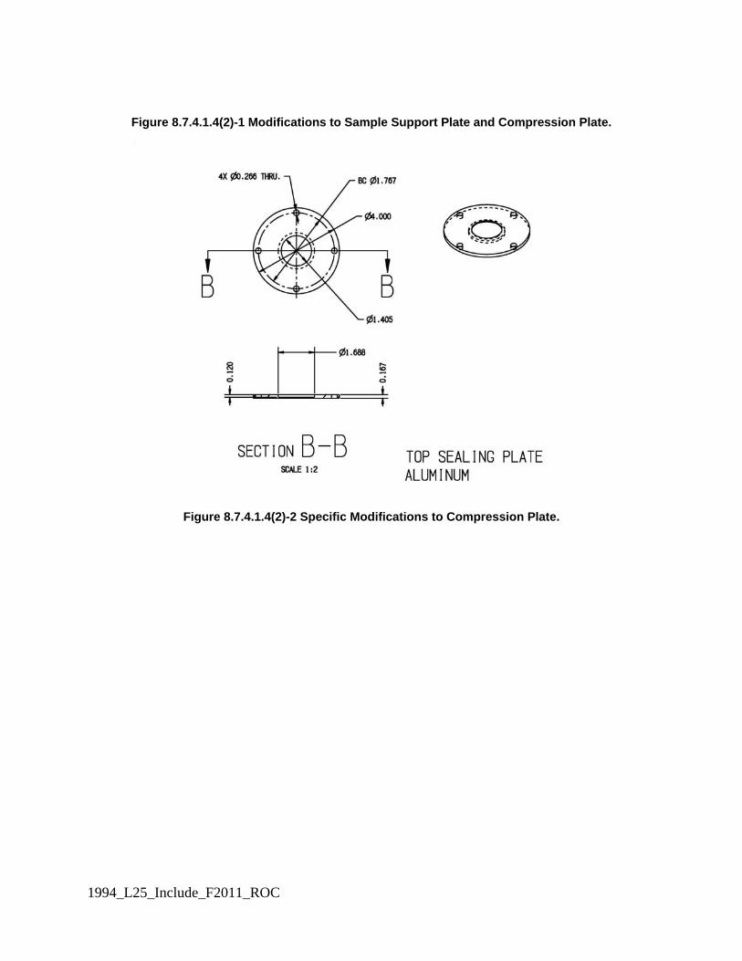
1994_L25_Include_F2011_ROC
Figure 8.7.4.1.4(2)-1 Modifications to Sample Support Plate and Compression Plate.
Figure 8.7.4.1.4(2)-2 Specific Modifications to Compression Plate.

1994_L25_Include_F2011_ROC
Figure 8.7.4.1.4(2)-3 Specific Modifications to Sample Support Plate.
8.7.4.1.5 Equipment shall be placed within the controlled environmental chamber to position the test cells horizontally and permit connection with the air delivery system and manifold. 8.7.4.1.6* An air delivery system and manifold shall be used to provide oil-free, conditioned air to the test cells/fixtures at a rate of 2 standard L/min (slpm) per test cell/fixture with a temperature precision of ±0.2°C and relative humidity precision of ±5 percent. The manifold is designed to deliver 1 L/min for the challenge side of the test cell and 1 L/min for the collection side of the test cell and maintain the test temperature. All parts of the air delivery system and manifold must be chemically inert and non-absorptive to the challenge chemical. 8.7.4.1.7* An analytical system shall be used to evaluate the amount of challenge chemical in the effluent air streams from the collection side of the test cell and shall be selected to provide the ability to measure the chemical at 0.1 μg/cm2 over the test exposure period. The analytical system shall be permitted to include a bubbler tube, solid sorbent, or real time chemical analyzer. Samples shall be permitted to be taken continuous, discretely, or cumulatively; however, the selected analytical system shall capture all challenge chemical emitted in the effluent air stream. 8.7.4.1.8 A vacuum pump capable of creating vacuum of at least 5 inches water column shall be used for testing the integrity of the assembled test cell. 8.7.4.1.9 A manometer or digital pressure gauge capable of measuring pressures or vacuums to 10 inches water column, with an accuracy of 5% scale, shall be used for testing the integrity of the assembled test cell. 8.7.4.2 Supplies. 8.7.4.2.1 Syringe needles, capable of delivering 1 μL ± 1% droplets of challenge chemical, shall be used for dispensing liquid chemicals onto the surface of the specimens in the test cell. 8.7.4.2.2 Replacement O-rings shall be available for use in the permeation test cell.

1994_L25_Include_F2011_ROC
8.7.4.2.2.1 If unknown, the compatibility of the O-ring material shall be verified before using the O-rings by placing the O-ring in contact with the chemical for a period of 4 hours and observing any physical changes to the O-ring within 10 minutes after the O-ring is removed from contact with the chemical. 8.7.4.2.2.2 If an O-ring shows any signs of chemical degradation in the form of softening, hardening, swelling, deterioration, or loss of shape, or function, an )-ring of different material shall be used that does not show chemical degradation. 8.7.4.2.3 Aluminum foil shall be used for the control and validation tests. 8.7.4.3 Chemicals. 8.7.4.3.1 The following chemicals shall be tested as liquids: (1) Liquid chemical warfare agents (a) Distilled sulfur mustard [HD; bis (2-chloroethyl) sulfide], 505-60-2 (b) Soman (GD; o-pinacolyl methylphosphonofluoridate), 96-64-0 (2) Liquid toxic industrial chemical (a) Dimethyl sulfate (DMS, sulfuric acid dimethyl ester), 77-78-1 8.7.4.3.2* The following chemicals gases shall be tested as gases or vapors in dry air or nitrogen: (1) Ammonia (NH3, 7664-41-7) (2) Chlorine (Cl2; 7782-50-5) (3) Acrolein (allyl aldehyde), 107-02-8 (4) Acrylonitrile (VCN, cyanoethylene), 107-13-1 8.7.5 Procedures. 8.7.5.1 Test Set Up. 8.7.5.1.1 The test cell holders and the air delivery system manifolds shall be installed in the environmental chamber and shall be prepared to receive the loaded test cells. 8.7.5.1.2 The analytical detection system shall be assembled and calibrated. 8.7.5.1.2.1 If bubblers are used, each bubbler shall be filled with the proper collection solvent using a calibrated pipetter or equivalent device; the collection solvent shall incorporate an internal standard so adjustments can be made for solvent evaporation/water condensation during sampling. 8.7.5.1.2.2 If solid sorbent tubes are to be used, each sorbent tube shall be cleaned by heating and purging; the absence of any residual chemical shall be verified by the appropriate analysis technique. Checks should also be made to determine that the flow rate through the test cells are not affected by the differential pressure through the sorbent tubes. 8.7.5.1.3 Each test cell shall be labeled. 8.7.5.1.4 All liquid chemicals shall be placed in the environmental chamber for a minimum of 24 hours prior to testing. 8.7.5.1.5 The air delivery system shall be turned on and shall be operated at 32.2 ± 2C (90 ± 3F) and 80 ± 5 percent relative humidity for a minimum of 30 minutes to achieve environmental equilibrium before swatch loading. 8.7.5.2 Test Cell Assembly. 8.7.5.2.1 The test cell shall be assembled 24 hours before specimen conditioning in the environmental chamber as shown in Figure 8.7.5.2.1. 8.7.5.2.2 An O-ring shall be placed on the lower body of test cell. 8.7.5.2.2.1 The testing of seams and other non-uniform profile specimens shall require special O-rings to ensure that test cell integrity is maintained. 8.7.5.2.3 The sample support plate shall be placed on O-ring 1 and O-ring 2 shall be placed in the groove on the sample support plate. 8.7.5.2.4 The specimen shall be removed from the conditioning location in the environmental chamber and shall be placed in the depression of the sample support plate with O-ring 3 placed over the specimen. 8.7.5.2.5 O-ring 4 shall be placed in the upper body of the test cell and the compression plate shall be positioned over O-ring 4. 8.7.5.2.6 O-ring 4 shall be inverted and the upper body shall be aligned with the lower body. 8.7.5.2.7 Using the four cell sealing lugs, the cell halves shall be clamped together and 51.8 cm-kg (45 in-lbs) of torque shall be applied to each lug to ensure a proper cell seal. 8.7.5.2.8 O-ring 5 shall be inserted into the groove around the agent challenge port in the upper body of the test cell and the cell cap shall be screwed into place.

1994_L25_Include_F2011_ROC
8.7.5.2.9 For semipermeable fabrics the integrity of the seal between O-ring 5 and the cell cap shall be visually inspected and the procedure in 8.7.5.3 shall be used to verify the test cell seal. 8.7.5.2.10 For impermeable fabrics tested in dual mode, the procedures in 8.7.5.4 shall be used to verify test cell seal.
Figure 8.7.5.2.1 Permeation Cell Assembly. 8.7.5.3 Verification of Test Cell Integrity (Permeable and Semipermeable Fabrics). 8.7.5.3.1 All ports shall be sealed except for the outlet port. 8.7.5.3.2 The cell shall be depressurized to 75 mm (3 in.) water column pressure by opening the valve slightly and watching the manometer. 8.7.5.3.3 When the pressure inside the test cell drops by 75 mm (3 in.) water column pressure, the valve shall be closed and the manometer shall be monitored for 2 minutes. 8.7.5.3.4 A 25 mm (1 in.) drop in water column pressure shall be considered failure to seal.

1994_L25_Include_F2011_ROC
8.7.5.3.5 If a test cell fails, the procedures in 8.7.5.2 for assembling the cell shall be repeated to reseal the cell. 8.7.5.3.6 Only cells that have passed this test shall be used for testing. 8.7.5.4 Verification of Test Cell Integrity (Impermeable Fabrics). 8.7.5.4.1 Before applying chemical challenge, each test cell shall be subjected to a vacuum of 75 mm (3 in.) water column pressure in the bottom chamber of the cell as measured by a manometer. 8.7.5.4.2 The pressure shall be maintained for 2 minutes. 8.7.5.4.3 The pressure drop shall be observed at 2 minutes. 8.7.5.4.4. Test cells shall be considered to have an adequate seal if the pressure drop is less than a 25 mm (1 in.) drop in water column pressure. 8.7.5.4.5 If a pressure drop of 25 mm (1 in.) drop in water column pressure or greater is observed, the procedures in 8.7.5.2 for assembling the cell shall be repeated to reseal the cell. 8.7.5.3.6 Only cells that have passed this test shall be used for testing. 8.7.5.5 Application of Liquid Chemical Challenge. 8.7.5.5.1 Eight 1-L droplets shall be placed evenly spaced around a 25.4 mm (1-in) diameter circle on the upper specimen surface and two 1-L droplets shall be placed 8.1 mm (1/3-in) apart in the center of the specimen. For seams, the two droplets shall be placed on the seam juncture. 8.7.5.5.1.1 A mechanical or automated device shall be permitted for uniformly dispensing the droplets onto the surface of the specimen. 8.7.5.5.2 Prior to any test with a new chemical, a quality control trial shall be conducted to verify the challenge level delivery process using the procedures in 8.7.5.6. 8.7.5.6 Verification of Liquid Chemical Challenge Method. 8.7.5.6.1 For 10 1-μL droplets, the mass ± 1 μg shall be determined using the density of the challenge chemical. 8.7.5.6.2 An inert specimen (aluminum foil) shall be placed in the test cell using the procedures described in 8.7.5.2. 8.7.5.6.3 The challenge chemical shall be applied to the inert specimen in the pattern described in 8.7.5.5. 8.7.5.6.4 After placement of the chemical, the specimen shall be visually inspected to verify that the agent was correctly applied. 8.7.5.6.5 The contaminated specimen shall be carefully removed and shall be placed in a closed large vial containing a known volume of solvent compatible with the analysis procedure. 8.7.5.6.6. The vial of solvent shall be agitated for at least one hour to ensure complete extraction of the challenge chemical from the swatch. 8.7.5.6.7 After agitation, the solvent vial shall be removed and submitted for analysis for challenge chemical using a procedure capable of detecting 1 μg using the density of the challenge chemical. 8.7.5.7 Test Start-Up for Liquid Chemical Challenges. 8.7.5.7.1 The test cells shall be installed in test cell holder prior to chemical challenge and all connections shall be ensured to have been properly made. 8.7.5.7.2 The operation of any analytical system shall be initiated according to its instructions. 8.7.5.7.3 After placing the challenge chemical on the specimen in the test cell, the cell cap shall be closed. 8.7.5.7.4 The air delivery system shall be immediately operated to provide filtered air at a temperature of 32°C ±2°C (90°F ±5°F) and a relative humidity of 80 percent ±5 percent, flowed through the collection chamber of the test cell at a rate of 1.0 Lpm ±0.1 Lpm. 8.7.5.7.4.1 For testing of Class 2 ensemble materials, the filtered air shall be flowed to collection sides of the test cells only. 8.7.5.7.4.2 For testing of Class 3 ensemble materials, the filtered air shall be flowed to both the challenge and collection sides of the test cells, each at a rate of 1.0 Lpm ±0.1 Lpm. 8.7.5.7.5 Challenge chemical in the effluent air streams shall be collected, measured, and analyzed either by using appropriate discrete sample methods or continuously. 8.7.5.7.5.1 If bubblers or sorbent tubes are used for collecting challenge chemical, bubblers or sorbent tubes shall be replaced at a prescribed frequency. 8.7.5.7.6 The collection media for challenge chemical shall be analyzed using an appropriate analytical procedure. 8.7.5.7.7 The exposure to challenge chemical shall be conducted for 60 minutes, -0,+1 minute.

1994_L25_Include_F2011_ROC
8.7.5.7.8 A minimum of three specimens shall be tested with challenge chemical. 8.7.5.7.9 At least one test shall be conducted with the specimen but without challenge chemical. 8.7.5.7.10 At least one test shall be conducted with an inert specimen (e.g., aluminum foil). 8.7.5.8 Test Start-Up for Gas or Vapor Chemical Challenges. 8.7.5.8.1 The test cells shall be installed in test cell holder prior to chemical challenge and all connections shall be ensured to have been properly made. 8.7.5.8.2 The operation of any analytical system shall be initiated according to its instructions. 8.7.5.8.3 The initial of the test shall occur when the gas or vapor chemical challenge is introduced into the test cell. 8.7.5.8.3.1 The flow of the gas or vapor chemical challenge shall be continuous over the exposure period of 60 minutes, -0,+1 minute. 8.7.5.8.3.2 The gas shall be at a temperature of 32°C ±3°C (90°F ±5°F). 8.7.5.8.3.3 For Class 2 ensembles, the concentration of the challenge chemical in the gas shall be 350 ppm +35 ppm/−0 ppm. 8.7.5.8.3.4 For Class 3 ensembles, the concentration of the challenge chemical in the gas shall be 40 ppm +10 ppm/−0 ppm. 8.7.5.8.4 The air delivery system shall be immediately operated to provide filtered air at a temperature of 32°C ±3°C (90°F ±5°F) and a relative humidity of 80 percent ±5 percent, flowed through the collection chamber of the test cell at a rate of 1.0 Lpm ±0.1 Lpm. 8.7.5.8.5 Challenge chemical in the effluent air streams shall be collected, measured, and analyzed either by using appropriate discrete sample methods or continuously. 8.7.5.8.5.1 If bubblers or sorbent tubes are used for collecting challenge chemical, bubblers or sorbent tubes shall be replaced at a prescribed frequency. 8.7.5.8.6 The collection media for challenge chemical shall be analyzed using an appropriate analytical procedure. 8.7.5.8.7 The exposure to challenge chemical shall be conducted for 60 minutes, -0,+1 minute. 8.7.5.8.8 A minimum of three specimens shall be tested with challenge chemical. 8.7.5.8.9 At least one test shall be conducted with the specimen but without challenge chemical. 8.7.5.8.10 At least one test shall be conducted with an inert specimen (e.g., aluminum foil). 8.7.5.9 Test Conclusion, Test Cell Clean Up and Specimen Disposal. 8.7.5.9.1 At the conclusion of the test, the air delivery and analytical systems shall be shut down. 8.7.5.9.2 The test cells shall be removed from the test cell holders after completion of each trial. 8.7.5.9.3 Each cell shall be disassembled one at a time. 8.7.5.9.4 The test specimen shall be removed and inspected for any degradation or obvious abnormalities; these observations shall be recorded with test results. 8.7.5.9.5 Each specimen shall be extracted using appropriate extraction procedures for challenge chemical. 8.7.5.9.6 The extracted protective clothing material specimens and test cell O-rings shall be disposed of according to local, stated, Federal or other applicable regulations. 8.7.5.9.7 Each component of the test cell shall be rinsed with acetone or other appropriate solvent to remove residual chemicals. 8.7.5.9.8 The cells shall be allowed to air-dry in a clean area between 4 and 24 hours before reuse. 8.7.5 8.7.6 Report. 8.7.5.1 For permeation testing of chemical warfare agents specified in 8.7.4.2(1), t 8.7.6.1 The cumulative permeation in 60 minutes shall be recorded and reported in μg/cm2 for each specimen. The average cumulative permeation in 1 hour for all specimens shall be calculated, recorded, and reported. The report shall include the pass or fail results for each chemical tested. 8.7.5.2 For permeation testing of liquid and gaseous industrial chemicals specified in 8.7.4.2(2) and 8.7.4.3, the normalized breakthrough time shall be recorded and reported in minutes for each specimen. The average normalized breakthrough time shall also be calculated and reported. 8.7.6.2 If no challenge chemical is detected at the end of the 60-minute test period, the cumulative permeation shall be reported as less than the minimum detectable mass per unit area for the specific chemical being tested. 8.7.6.3 The average cumulative permeation shall be calculated for all specimens for each challenge chemical.

1994_L25_Include_F2011_ROC
8.7.6.3.1 If no challenge chemical is detected for one or two specimens, the average cumulative permeation shall be the average of all specimens where the cumulative permeation is measured and the minimum detectable cumulative permeation for those specimens where no challenge chemical is detected. 8.7.6.3.2 If no challenge chemical is detected in all of the specimens tested, the average cumulative permeation shall be reported as less than the minimum detectable mass per unit area for the specific chemical being tested. 8.7.6.4 Observations for the condition of the specimen following the test shall be provided with the test results. 8.7.6 8.7.7 Interpretation. 8.7.6.1 For permeation testing of chemical warfare agents specified in 8.7.4.2(1), t The average cumulative permeation shall be used to determine pass or fail performance. 8.7.6.2* For permeation testing of liquid and gaseous industrial chemicals specified in 8.7.4.2(2) and 8.7.4.3, the average normalized breakthrough time shall be used to determine pass or fail performance. 8.7.7 8.7.8 Specific Requirements for Testing Garment Materials. 8.7.7.1 8.7.8.1 Samples shall be conditioned by flexing as specified in 8.1.3. Samples shall be 200 mm × 280 mm (8 in. × 11 in.). Following flexing, one specimen shall be taken from the center of each sample subjected to flexing for permeation resistance testing. 8.7.7.2 8.7.8.2 Samples shall be conditioned by abrading as specified in 8.1.4. Samples shall be as specified in Figure 8.1.4. Following abrading, one specimen shall be taken from the center of each sample subjected to abrading for permeation resistance testing. 8.7.7.3 8.7.8.3 It shall be permitted to precondition one sample to both flexing and abrading prior to permeation resistance testing. 8.7.8 8.7.9 Specific Requirements for Testing Visor Materials. Samples for conditioning shall be visor materials. 8.7.9 8.7.10 Specific Requirements for Testing Glove Materials After Flexing. 8.7.9.1 8.7.10.1 Samples for conditioning shall be whole gloves. 8.7.9.2 8.7.10.2 Samples shall be conditioned as specified in 8.1.5. 8.7.10 8.7.11 Specific Requirements for Testing Footwear Materials After Flexing and Abrading. 8.7.10.1 8.7.11.1 This test shall apply to all types of footwear configurations. 8.7.10.2 8.7.11.2 Where the footwear incorporates a sock or overboot constructed of garment material, the garment material flex fatigue resistance test as specified in 8.1.3 shall be permitted to be substituted for this test. 8.7.10.3 8.7.11.3 Upper samples for conditioning shall be whole footwear items. 8.7.10.4 8.7.11.4 Upper samples shall first be conditioned by flexing as specified in 8.1.6. 8.7.10.5 8.7.11.5 Following flexing, new upper samples shall be taken in areas from the footwear upper where the greatest flexing occurred, usually at the footwear quarter or vamp, and shall be as specified in Figure 8.1.4. 8.7.10.6 8.7.11.6 Sole samples for conditioning shall be taken from the footwear or shall be permitted to be facsimile samples of sole material where the facsimile samples are the same composition and construction of the sole used in actual footwear. 8.7.10.6.1 8.7.11.6.1 Facsimile sole samples shall be of a maximum thickness representative of the thinnest portion of the sole, exclusive of hardware, midsoles, or inner soles. 8.7.10.6.2 8.7.11.6.2 Where facsimile samples are elected, the sole samples shall not be subjected to the flexing specified in 8.7.10.4. 8.7.10.6.3 8.7.11.6.3 Specific Requirements for Testing Thermoplastic Sole Compositions. Samples shall be compression mold samples with a consistent thickness from the thermoplastic compound used to manufacture the footwear sole or from the actual sole. 8.7.10.6.4 8.7.11.6.4 Specific Requirements for Testing Vulcanized Sole Compositions. Samples shall be compression mold samples with a consistent thickness from the nonvulcanized compound used to manufacture the footwear sole.

1994_L25_Include_F2011_ROC
8.7.10.6.5 8.7.11.6.5 Specific Requirements for Testing Thermoset Sole Compositions. Samples shall be compression mold samples with a consistent thickness from the thermoset material used to manufacture the footwear sole. 8.7.10.7 8.7.11.7 The upper samples that were taken per 8.7.10.5, and sole samples shall then be conditioned by abrading as specified in 8.1.4. 8.7.10.8 8.7.11.8 Following abrasion, only one test specimen for chemical permeation resistance testing shall be taken from each sample subjected to abrasion. 8.7.10.9 8.7.11.9 The chemical permeation test specimen shall be taken from the exact center of the abraded sample so that the center of the permeation test specimen and the center of the abraded specimen coincide. 8.7.11 8.7.12 Specific Requirements for Testing Garment, Visor, and Glove Seams. 8.7.11.1 8.7.12.1 Samples for conditioning shall be 600 mm (231⁄2 in.) lengths of prepared seam or cut from ensembles. 8.7.11.2 8.7.12.2 Seam specimens shall be prepared from seam samples that have a minimum of 75 mm (3 in.) of material on each side of the seam center. 8.7.11.3 8.7.12.3 Permeation test specimens shall be cut such that the exact seam center divides the specimen in half. 8.7.11.4 8.7.12.4 Seam specimens shall be prepared representing each different type of seam found in the garment, or shall be taken from each different type of seam found in the garment, including as a minimum the garment-to-garment material seams and the garment-to-visor material seams. 8.7.11.5 8.7.12.5 Seam specimens shall be taken from gloves from the gauntlet portion of the glove when an external seam is used in the construction of the glove. A.8.7.6.2 In ASTM F 739, Standard Test Method for Resistance of Protective Clothing Materials to Permeation by Liquids or Gases Under Conditions of Continuous Contact, normalized breakthrough time is the time at which permeation of the challenge chemical through the specimen exceeds 0.1 μg/cm2/min. If the permeation rate does not exceed this 0.1 μg/cm2/min, the normalized breakthrough time is reported as greater than the test duration, or, in this case, >60 minutes. However, this does not mean that breakthrough did not occur. If the permeation rate remained slightly under 0.1 μg/cm2/min for the 60-minute duration of this procedure, a level of 6 μg/cm2/min of chemical would have permeated. A.8.7.4.1.4 A test cell meeting these requirements is available from Aerospace Tooling & Machining, 2190 West 1700 South, Salt Lake City, UT 84104. A.8.7.4.1.6 It is essential that the air delivery system provide precise flow to each test cell and achieve the specified temperature and humidity conditions. This delivery is controlled by the conditioning of the incoming air to achieve the temperature and humidity conditions before reaching each test cell and is monitored by separate flow meters or controllers for each test cell. A.8.7.4.1.7 It is not required to provide an analytical and sampling approach that provides discrete measurements of cumulative permeation as the criterion for this test is based on total cumulative permeation over a one hour period. This approach allows complete collection of any permeating chemical and subsequent analysis. The efficacy of the selected sampling and analysis approach should be validated for each challenge chemical through the use of procedure where a known amount of the challenge chemical representative of a cumulative permeation close to the minimum requirement is injected into the collection medium of a trial test. The selected sampling and analytical approach should be able to demonstrate a recovery of 95% or better to be considered a valid part of the procedures. A.8.7.4.3.2 It is recommended that the concentrations for the gases be achieved by ordering prepared gas mixtures at the prescribed concentration. Add the following additional references: In section 2.3.2, ASTM Publications: ASTM D 1777 Test Method for Thickness of Textile Materials, 2007. ASTM D 3776 Standard Test Methods for Mass per Unit Area (Weight) of Fabric, 2009. In section 2.3.6, Military Publications:
1994_L25_Include_F2011_ROC
Test Operations Procedure (TOP 10-2-022), Man-In-Simulant Test (MIST) — Chemical Vapor Testing of Chemical/Biological Protective Suits, September 2001. Test Operations Procedure (TOP) 8-2-501, Permeation and Penetration Testing of Air-Permeable, Semipermeable, and Impermeable Materials with Chemical Agents or Simulants (Swatch Testing), Report No. WDTC-TR-99-095, January 2002

Report on Comments – November 2011 NFPA 1994_______________________________________________________________________________________________1994- Log #16 FAE-HAZ
_______________________________________________________________________________________________Technical Correlating Committee on Fire and Emergency Services Protective Clothing and Equipment,
1994-40
This is a direction from the Technical Correlating Committee on Hazardous Materials ProtectiveClothing and Equipment in accordance with 3.4.2 and 3.4.3 of the Regulations Governing Committee Projects.
_______________________________________________________________________________________________1994- Log #13 FAE-HAZ
_______________________________________________________________________________________________Daniel J. Gohlke, W. L. Gore and Associates
1994-1Change reference from "ASTM F 1868" to "ASTM F 1868-02".
The new revision of ASTM F 1868 introduces new techniques for handling composites that distortdimensionally during the test. This revision alters the standard values on which NFPA's performance requirements arebased and introduces a bias caused by the special handling of these materials. And will allow materials that previouslyfailed to pass.
7Printed on 3/11/2011

F2011 - NFPA 1994 - Log #20 - Table 1
NFPA Technical Correlating Committee on Fire and Emergency Service Protective Clothing and Equipment
NFPA 1994
Table for Log 20 Table of Recommended Changes to Permeation Resistance Test Method Test Parameter Current Specification Proposed Change Referenced standards ASTM F 739 ASTM D 1777 for thickness
measurement; ASTM D 3776 for unit area weight measurement
Test environment None; however, testing to be performed at 32 ±1oC
All testing to be performed in separate test chamber that will be maintained at test conditions; specimens, chemicals, and test apparatus will be placed in chamber and required to be in place 24 hrs prior to testing
Test cell Per ASTM F 739, alternative test cells permitted; no requirements for determining equivalency
Modified TOP 8-2-501 test cell with drawing specification for modified specimen plate to accommodate control of exposed surface area in saturated surface exposure tests; test cap to contain fitting for measuring integrity of test cell after specimen is mounted
Air flow requirements in collection side
Filtered air at rate of 1 ±0.1 Lpm at 80 ±5% RH
Balance air flow with challenge side for consistency and absence of pressure drop; measure temperature and relative humidity at test cell inlet; principal air flow system to be positioned inside environmental chamber
Specimen size Varies with test cell Standardized for TOP 8-2-501 test cell
Permeation specimen conditioning
21 ±3°C and 65 ±5% RH (standard textile conditioning)
32 ±1oC and 80 ±5% RH to be conducted inside test chamber; tolerance on temperature to be relaxed to ±2oC
Test cell sealing None Alternative gasketing material to be specified; O-rings and fittings must be assessed for compatibility with test chemical; Specific torque to be applied in sealing test cell

F2011 - NFPA 1994 - Log #20 - Table 2
Test Parameter Current Specification Proposed Change Test cell integrity check
None Using fitting in test line cap, test cell to be pressurized with air to 2 psig with specimen in place with pressure drop measured after 1 minute (only 10% pressure drop permitted)
Liquid challenge conditions
Liquid applied at surface density of 10 g/m2 using appropriate number of 1-μL droplets uniformly dispensed on material specimen surface
For each liquid chemical (including chemical warfare agents), nine (9) 1-μL droplets will be applied in specific pattern on exposed specimen surface; time of 30 seconds will be required for opening test cell cap, dispensing droplets, and closing test cell cap.
Air flow on challenge side for open top test cell configuration
Filtered air at rate of 0.3 ±0.03 Lpm at 80 ±5% RH
Filtered air at rate of 0.3 ±0.03 Lpm at 80 ±5% RH, temperature conditioning with environmental chamber
Volatile liquid toxic industrial chemical challenge
None Chemicals with vapor pressures of 5 mm Hg or greater at 25oC will be tested as vapors at the corresponding gas concentration in the respective standard
Collection technique Combination of analytical technique and collection medium shall be selected to maximize sensitivity for the detection of the test chemical and represent actual occupational conditions as closely as possible
Test system collection efficiency evaluated using procedure to determine total test chemical collected; evaluation must be performed for each test chemical and verified periodically by laboratory
Analytical sensitivity Test system must have detection limit that is one order of magnitude lower than prescribed permeation end point
Specification to be based on each individual chemical; good laboratory practice standards will be referenced for correct analytical procedures
Results reported Breakthrough time Permeation rate (optional) Test parameters as part of report
Cumulative permeation Test parameters as part of report
Interpretation of results Average of all results Average of all results; however, if one or two test cells show no cumulative permeation, the standard-defined minimum detection limit will be used for no detectable permeation test results for purposes of averaging results

Report on Comments – November 2011 NFPA 1994_______________________________________________________________________________________________1994- Log #21 FAE-HAZ
_______________________________________________________________________________________________Holly Blake, WL Gore & Associates
N/ARevise text to read as follows:
Testing shall be conducted in accordance with ASTM F 1868, Standard Test method for Thermal andEvaporative Resistance of Clothing Materials Using a Sweating Hot Plate, using Part C, with the following modifications:
(1) The specimen shall be placed on the test plate with the side normally facing the human body toward the test plate.(2) For multiple layers, arrange the layers in the order and orientation as worn.(3) Smooth each layer by hand to eliminate wrinkles or bubbles in each layer and, if necessary, secure the edges.(4)* Once the test is started, no further adjustments to the specimen shall be made.*Annex 8.6.5 These modifications shall be used instead of Note 6 in ASTM F1868 Part C.
The new revision of ASTM F 1868 has introduced new techniques via Note 6 for handling compositesthat distort dimensionally during the test. The standard values of performance in Total Heat Loss testing are dependenton the test parameters and procedures. By modifying the testing and handling techniques of the specimen, Note 6 hasthe unintended consequence of modifying standard values. It can allow material systems that previously failed therequirements to pass. Furthermore, the instructions are biased and unclear. For example, in a multi-layer composite, it isdifficult to determine, which layer, if any, is not laying flat per Note 6. By preferentially re-smoothing one or more of thelayers in one composite, and not all layers, or not all composites, Note 6 introduces bias. It is unclear when to implementNote 6 or which parts of Note 6. When is a flat specimen no longer flat? It also introduces a bias by assuming materialsonly change dimensionally under the conditions of the test, and therefore preferentially attempts to correct for only thisone effect. A uniform handling of the specimens is needed as this comment recognizes.
_______________________________________________________________________________________________1994- Log #14 FAE-HAZ
_______________________________________________________________________________________________Daniel J. Gohlke, W. L. Gore and Associates
1994-1Add new "8.12.7.2 Specimens shall be conditioned as specified in 8.1.3."
No specimen preconditioning is given.
_______________________________________________________________________________________________1994- Log #19 FAE-HAZ
_______________________________________________________________________________________________Technical Correlating Committee on Fire and Emergency Services Protective Clothing and Equipment,
1994-44
This is a direction from the Technical Correlating Committee on Hazardous Materials ProtectiveClothing and Equipment in accordance with 3.4.2 and 3.4.3 of the Regulations Governing Committee Projects.
8Printed on 3/11/2011

Report on Comments – November 2011 NFPA 1994_______________________________________________________________________________________________1994- Log #2 FAE-HAZ
_______________________________________________________________________________________________William Alexander, Onguard Industries
1994-44Revise text as follows:
Is there enough test data of currently certified footwear to ensure continued compliance to the proposed footwear testmethod for slip resistance?
No substantiation provided.
_______________________________________________________________________________________________1994- Log #4 FAE-HAZ
_______________________________________________________________________________________________William Alexander, Onguard Industries
1994-44Revise text to read as follows:
8.19.4(1) A minimum of three complete size 9 footwear items shall be tested in the flat and heel positions.
The surface contact area of different sizes of footwear will affect the static coefficient of friction. Thesize 9 is the typical median size.
9Printed on 3/11/2011