medium-voltage - · pdf fileup to 40.5 kv, gas-insulated medium-voltage switchgear catalog ha...
TRANSCRIPT

Fixed-Mounted Circuit-BreakerSwitchgear, Types 8DA and 8DB,up to 40.5 kV, Gas-Insulated
Medium-VoltageSwitchgear
Catalog HA 35.112006
Invalid:Catalog HA 35.11 · 2003

Fixed-Mounted Circuit-Breaker Switchgear, Types 8DA and 8DB, up to 40.5 kV, Gas-Insulated
2 Siemens HA 35.11· 2006
© Siemens AG 2006
R-HA
35-0
96ep
s
R-HA
35-0
95ep
s
R-HA
35-0
94ep
s
Contents Application
TypesPage
Fixed-mountedcircuit-breaker switchgear
• 8DA10 for single-busbar applications• 8DA11/8DA12 (1-pole and 2-pole design)
for traction power supply systems• 8DB10 for double-busbar
applications
are metal-enclosed,metal-clad and gas-insulatedswitchgear forindoor installation.
Application
Types, typical uses 2 to 4
Requirements
Features, safety, technology 4 and 5
Technical Data
Electrical data, dimensions 6Constructional data 7Room planning, floor openingsand fixing points 8Shipping data 9
Product Range
Single-busbar panels 10Double-busbar panels 11 to 13
Design
Basic panel design 14 and 15
Components
Busbars 16Three-position disconnector 17Vacuum circuit-breaker 18 and19Current and voltage transformers 20 and 21Panel connection 22 and 23Control board 24Indicating and measuring equipment 25 and 26Low-voltage equipment 27 and 28
Standards
Standards, specifications, guidelines 29 to 31
Notes
31
8DA10panelfor single-busbarapplications
8DA11/8DA12panelfor traction powersupply systems,1-pole and 2-poledesign(example 8DA11)
8DB10panelfor double-busbarapplications

Fixed-Mounted Circuit-Breaker Switchgear, Types 8DA and 8DB, up to 40.5 kV, Gas-Insulated
3Siemens HA 35.11· 2006 3
R-HA
35-0
90a
eps
R-HA
35-1
01ep
s
R-HA
35-0
98ep
s
R-HA
35-0
99ep
s
ApplicationIndustry
ApplicationPublic powersupply system
8DA10 switchgearfor single-busbarapplications
ApplicationTraction powersupply system
Typical uses
Application

Fixed-Mounted Circuit-Breaker Switchgear, Types 8DA and 8DB, up to 40.5 kV, Gas-Insulated
4 Siemens HA 35.11· 2006
Typical uses Features
Application Requirements
Fixed-mounted circuit-breaker switchgear8DA and 8DB is used in transformerand switching substations, e.g.
ApplicationPublic power supply system with 8DA10/8DB10
■ Power supply companies
ApplicationIndustry with 8DA10/8DB10
■ Power stations■ Cement industry■ Automobile industry■ Iron and steel works■ Rolling mills■ Mining industry■ Textile, paper and food industries■ Chemical industry■ Petroleum industry■ Pipeline installations■ Offshore installations■ Electrochemical plants■ Petrochemical plants■ Shipbuilding industry■ Diesel power plants■ Emergency power supply installations■ Lignite open-cast mines■ Traction power supply systems
Applicationfor single-pole and double-pole designwith 8DA11/8DA12
■ Traction power supply systems
Environmental independence
Enclosures with modular stand-ard housings made of corro-sion-resistant aluminium alloymake 8DA and 8DB switchgear
• Insensitive to aggressiveambient conditions such as
– salt water– air humidity– dust– temperature
• Primary part is hermeticallytight to ingress of foreignbodies, such as
– dust– dirt
• Independent of site altitude
Compact design
Thanks to the gas insulation,narrow panel widths of only600 mm up to 40.5 kVare possible.
Thus,
• Existing switchgear roomscan be used effectively
• New constructions cost little
• Costly city-area space is saved
Almost maintenance-freedesign
Switchgear housings designedas sealed pressure systems,maintenance-free switchingdevices and enclosed cableplugs ensure
• Maximized power supplyreliability
• Personnel safety
• Reduced operating cost
• Cost-efficient investment
Innovations
The use of digital secondarysystems and combined protec-tion and control devices ensure
• Clear integration in processcontrol systems
• Flexible and highly simplifiedadaption to new systemconditions and thus tocost-efficient operation

5Siemens HA 35.11· 2006
Fixed-Mounted Circuit-Breaker Switchgear, Types 8DA and 8DB, up to 40.5 kV, Gas-Insulated
Personal safety
• Safe-to-touch andhermetically sealed primaryenclosure
• All high-voltage parts includ-ing the cable terminations,busbars and voltage transfor-mers are surrounded byearthed layers or metal en-closures
• Capacitive voltage detectionsystem for verification of safeisolation from supply
• Operating mechanisms andauxiliary switches safelyaccessible outside the pri-mary enclosure (switchgearhousings)
• Protective system interlock toprevent operation when theenclosure is open
• Standard degree of protec-tion IP65 (primary part) andIP3XD (secondary part) accor-ding to IEC 60 529 and VDE0470-1Option: Degree of protectionIP31D for low-voltage com-partment
• High resistance to internalarcs by logical mechanicalinterlocks and tested enclo-sure
• Arc-fault classified panelsaccording to IEC 62 271-200
• Mechanical and/or electricalinterlocks prevent malopera-tion
Security of operation
• Hermetically sealed primaryenclosure independent ofenvironmental effects (dirt,moisture and small animals)
• Operating mechanisms ofswitching devices accessibleoutside the primary enclo-sure (switchgear housings)
• Metal-enclosed, plug-ininductive voltage transform-ers mounted outside the gascompartments
• Ring-core current transform-ers mounted outside the gascompartments
• Complete logical mechanicalinterlocking system
• Option: Aseismic design
• Minimum fire load
Reliability
• Type and routine-tested
• Standardized, NC productionprocesses
• Quality assurance in accor-dance with DIN EN ISO 9001
• More than 38,000 switch-gear panels of Siemens inoperation worldwide formany years
General
• Single-pole enclosure of pri-mary conductors
• Insulating gas SF6
• Three-position disconnectoras busbar disconnector andfeeder earthing switch
• Make-proof earthing withvacuum circuit-breaker
• Outgoing and incomingfeeder panel width: 600 mm
• Enclosure with standardhousings made of corrosion-resistant aluminium alloy
• Cable connection with inside-cone plug-in systems, orconnection of solid-insulatedor gas-insulated bars
• Existing switchgearextendable on both sides
Modular design
• Circuit-breaker or cable termi-nation can be replaced with-out disconnecting the busbar
• Extension of double-busbarswitchgear 8DB10(option: without interruptingoperation of existing feeders)
• Low-voltage compartmentcan be removed without in-terrupting the bus wires
Safety
Instrument transformers
• Can be removed without al-tering the position of thebusbar modules (outside thegas compartments)
Vacuum circuit-breaker
• Maintenance-free undernormal ambient conditionsaccording to IEC 60 694 andVDE 0670-1000
• No relubrication oradjustment
• Up to 10,000 electricaloperating cycles
• Up to 30,000 mechanicaloperating cycles
• Vacuum-tight for life
Secondary systems
• Digital multifunction protec-tion relay with integratedprotection, control, commu-nications, operating andmonitoring functions
• Can be integrated in processcontrol systems
Technology
Requirements

Fixed-Mounted Circuit-Breaker Switchgear, Types 8DA and 8DB, up to 40.5 kV, Gas-Insulated
6 Siemens HA 35.11· 2006
Dimensions in mm (dim. drawings see page 7)Width B1
Incoming feeder panel 600Track section outgoing feeder panel 600
Switchgear end wall width B2
For left and right side of switchgear 152
Depth T
For 8DA11, 1-pole 865For 8DA12, 2-pole 1245
Height H1
Standard 2350
Height H2
Standard 1850
Dimensions in mm (dimension drawings see page 7)Width B1
Circuit-breaker panel 600 600Disconnector panel 600 –Bus coupler – 600Bus sectionalizer (2 panels) 2 x 600 2 x 600Bus sectionalizer for connection in cablebasement (2 panels)
2 x 600 2 x 600
Spare panel 600 600
Switchgear end wall width B2
For left and right side of switchgear 152 152
Depth T
For all panel types 1625 2660
Height H1
Standard 2350 2350With high low-voltage compartment 2700 2700With make-proof busbarearthing switch
2700 2700
Height H2Standard 1850 2100With make-proof busbarearthing switch
1960 2210
With top-mountedbus sectionalizer
2320 2570
Busbar fittings without disconnecting facility:
With voltage transformer up to 24 kV36/40.5 kV
21602225
24102475
With cable connection for- 1 plug, interface type 2 2050 2300- 1 plug, interface type 3 2030 2280- 2 or 3 plugs, interface type 2 2110 2360- 2 or 3 plugs, interface type 3 2130 2380- 4 to 6 plugs, interface type 2 2250 2500With connection for fully insulated bar 5) 1930 2180
Busbar fittings with disconnecting facility:
With voltage transformer up to 24 kV36/40.5 kV
23602455
26102705
With cable connection for
- 1 plug, interface type 2 2180 2430
- 1 plug, interface type 3 2240 2490
- 2 or 3 plugs, interface type 2 2240 2490
- 2 or 3 plugs, interface type 3 2260 2510
- 4 to 6 plugs, interface type 2 2380 2630
With connection for fully insulated bar 5) 2130 2380
Designation 8DA103-pole
8DB103-pole
Rated valuesRated
-voltage max. kV 12 24 1) 36 40.5 2) 12 24 36 40.5-frequency 50 Hz 3) 50 Hz 3)
-short-dur. power-frequency withst. volt. kV 28 50 70 85 4) 28 50 70 85
-lightning impulse withstand voltage kV 75 125 170 185 75 125 170 185
-short-circuit breaking current max. 40 kA max. 40 kA
-short-time withstand current, 3 s max. 40 kA max. 40 kA
-short-circuit making current max. 100 kA max. 100 kA
-peak withstand current max. 100 kA max. 100 kA
-normal current of busbar max. 4000 A max. 4000 A
-normal current of feeders max. 2500 A max. 2500 A
Ambient temperature -5 to + 55 °C
Designation 8DA11/8DA121-/2-pole
Rated valuesRatedvoltage according to kVIEC 60 850 and EN 50 163
15 25
-voltage kV 17.5 27.5-frequency Hz 16.7 50/60-short-duration to earth kVpower-frequency across isola- kVwithstand voltage ting distance
5060
95110
-lightning impulse to earth kVwithstand voltage across isola- kV
ting distance
125145
200220
-short-circuit breaking current max. 31.5 kA-short-circuit making current max. 80 kA-normal current of busbar max. 2500 A-normal current of feeders max. 2000 AAmbient temperature -5 to + 55 °C
Footnotes for left-hand table column:
1) Acc. to Russian GOST standard for 6/10 kV systems
2) Acc. to Russian GOST standard for 36 kV systems
3) 60 Hz on request
4) Rated short-duration power-frequency withstandvoltage 95 kV possible according to GB standard
5) Dimensions must be co-ordinatedwith the bar supplier
Electrical data, dimensions
Technical Data

7Siemens HA 35.11· 2006
Fixed-Mounted Circuit-Breaker Switchgear, Types 8DA and 8DB, up to 40.5 kV, Gas-Insulated
��
���������� �
�� ��
�
��
��� ��� ��� ���
��
���
����������� �
��
����������� �
�� ��
�
��
��� ���
��
���
����������� �
�
��
��� ��� ���
��
���
������������ �
��
����������� �
�� ��
�
��
��� ��� ���
��
���
����������� �
���
Front view
Side view
Front view
Side viewfor 8DA11, 1-pole
Side viewfor 8DA12, 2-pole
Side view
Front view
8DA10 3-poleSingle busbar
8DB10 3-poleDouble busbar
8DA11 1-pole, 8DA12 2-pole
Constructional data (see also dimension table on page 6)
Technical Data

Fixed-Mounted Circuit-Breaker Switchgear, Types 8DA and 8DB, up to 40.5 kV, Gas-Insulated
8 Siemens HA 35.11· 2006
����������������������������������������������������������������������������� � �����
����
���
���
����
���
����
�� ��
���
������������ �
��
�����
��
��
�������� ���
���������
��
���
���
�
�
�
�
�
�
�
���������������������������������������������������������������������������� � �����
���������
���
�� �� ���
����
���
����
���
������������ �
��
�����
��
��
������ ���
��������
��
���
���
�
�
�
�
�
�
�
���
������������ �
��
�����
��
��
������ ���
��������
�� ���
���
�
�
�
�
�
�
�
�������������������������������������������� � ��� ����������������������������������������������������������������������������������������������� � �����
����
����
�� �� ���
�����
���
�����
���
����������� �
����
�����
��
�������� ���
�������������
��
���
������
�
�
�
�
�
�
�
�
8DA10 3-poleSingle busbar
8DA11 1-pole, 8DA12 2-pole 8DB10 3-poleDouble busbar
8DA111-pole
8DA122-pole
5 Floor opening forprimary cables
6 Fixing hole in thebase frame
7 Rear edge ofbase frame
Room planning, floor openings and fixing points
Technical Data
Room planning (dimension B1 see page 7)
Room height ≥ 2850 mm 1)
Door dimen- dependent onsions – the number of panels
per transport unit and– the transport dimen-
sions (see page 9)
Net weight approx. 750 kg per panel
Room planning (dimension B1 see page 7)
Room height ≥ 2850 mm 1)
Door dimen- dependent onsions – the number of panels per transport unit and
– the transport dimensions (see page 9)
Net weight approx. 1200 kg per panel
* For switchable fittings at the busbar W 1000 mm(optionally on the left or right)
* 865 mm for 8DA11,1245 mm for 8DA12
Room planning (dimension B1 see page 7)
Room height ≥ 2850 mm 1)
Door dimen- dependent onsions – the number of panels
per transport unit and– the transport dimen-
sions (see page 9)
Net weight – approx. 400 kg for 8DA11per panel: – approx. 500 kg for 8DA12
Floor openings andfixing points
Floor openings
• Foundation as steel-reinforced con-crete or steel structure with lower, ad-justable support columns (false floor)
• Floor opening below each row ofpanels should be continuous
Fastening
Connection of the panel base frame to thefoundation rails below the fixing holes:– as bolted joints or– welded design
Legend
1 Base frame
Floor opening for control cables:2 For end panels3 Central arrangement (standard)4 Option
5 Floor opening for primary cables
6 Fixing hole in the base frame
7 Rear edge of base frame
Floor openings and fixing points
Floor openings
• Foundation as steel-reinforced concrete or steel struc-ture with lower, adjustable support columns (false floor)
• Floor opening below each row of panels should becontinuous
Fastening
Connection of the panel base frame to the foundationrails below the fixing holes:– as bolted joints or– welded design
Legend
1 Base frame
Floor opening forcontrol cables:2 For end panels3 Central arrangement
(standard)4 OptionFloor openings and
fixing points
Floor openings as per left-hand column
Fastening as per left-hand column
Legend as per left-hand column
** Size of floor opening (5) may be reduced if the switchgearrow is configured “without bus sectionalizers for connec-tion in cable basement”: Dimension 80 ** changes to440 mm and dimension 2180** changes to 1820 mm
1) Dimension 2850 mm applies to standard panel height.Room height with further busbar fittings = Actual panel height (see page 6) + 300 mm

Transport units
The following must benoted when definingthe transport units:
• Transport facilitieson site
• Transport dimensions andweights
• Size of door openings inbuilding
Packing
Place of destination insideGermany or other Europeancountries
• Method of transport:Rail and truck
• Type of packing:– panels on open pallets,
pallet height = 200 mm– open packing with
PE protective foil
Place of destination overseas
• Method of transport:Ship
• Type of packing:– panels on open pallets,
pallet height = 200 mm– in closed crates with sealed
upper and lower PE pro-tective foil
– with desiccant bags– with sealed wooden floor– max. storage time: 6 months
Fixed-Mounted Circuit-Breaker Switchgear, Types 8DA and 8DB, up to 40.5 kV, Gas-Insulated
9Siemens HA 35.11· 2006
Technical Data
Shipping data
Transport unit Numberof panels
8DA10single-busbar panels
max. 4
8DA11(1-pole) and8DA12 (2-pole)panels for tractionpower supply systemsin 1-pole or 2-poleapplications
max. 4
8DB10double-busbar panels
max. 3
8DA10 single busbars
Transport dimensions
Panel width
mm
Transport dimensionsWidth x Height x Depth
mm x mm x mm
Transport inside Germany or to other European countries
1 x 600 1764 x 2550 1) x 1840
2 x 600 1764 x 2550 1) x 1840
3 x 600 2400 x 2550 1) x 1840
4 x 600 2964 x 2550 1) x 1840
Transport Overseas
1 x 600 1764 x 2700 2) x 1864
2 x 600 1764 x 2700 2) x 1864
3 x 600 2400 x 2700 2) x 1864
4 x 600 2964 x 2700 2) x 1864
Transport weights *
Panel width
mm
Transport weightwith withoutpacking packing
approx. kg approx. kg
1 x 600 850 750
2 x 600 1700 1500
3 x 600 2550 2250
4 x 600 3400 3000
1) Height for standard panel:1200 mm high low-voltagecompartment and/or busbarfittings result in other heights(see page 6).
2) 3050 mm high in case of1200 mm high low-voltage boxand busbar voltage transformer36/40.5 kV with disconnectingfacility
3) 3050 mm high in case of1200 mm high low-voltage box,busbar voltage transformer 36/40.5 kV without disconnectingfacility, busbar voltage transfor-mer w 24 kV with disconnectingfacility and busbar connection4 to 6 times plug size 2 withdisconnecting facility
* Average values dependingon the degree to which panelsare equipped
8DB10 double busbars
Transport dimensions
Panel width
mm
Transport dimensionsWidth x Height x Depth
mm x mm x mm
Transport inside Germany or to other European countries
1 x 600 1816 x 2550 1) x 3124
2 x 600 1816 x 2550 1) x 3124
3 x 600 2416 x 2550 1) x 3124
Transport Overseas
1 x 600 1840 x 2850 3) x 3124
2 x 600 1840 x 2850 3) x 3124
3 x 600 2440 x 2850 3) x 3124
Transport weights *
Panel width
mm
Transport weightswith withoutpacking packing
approx. kg approx. kg
1 x 600 1300 1200
2 x 600 2600 2400
3 x 600 3900 3600

Siemens HA 35.11· 2006
Fixed-Mounted Circuit-Breaker Switchgear, Types 8DA and 8DB, up to 40.5 kV, Gas-Insulated
10
����������� �
������������ �
������������ �
Single-busbar panels 8DA10 , 3-pole ( 8DA11 , 1-pole and 8DA12 , 2-pole panels, on request)
Product Range
Circuit-breakerpanel
Disconnector panel
Same fittings andconnections asfor circuit-breakerpanel
Bus sectionalizer
Consisting of2 panels(circuit-breakerarranged in left-handor right-handpanel optionally)
Busbar fittings
Panel connectionfittings
Fitting at thecircuit-breaker housing
Fitting over thepanel connection
Fitting at thepanel connection
Panel connectionfittings
Fitting over thepanel connection
Fitting at thebus riser housing
Busbar fittings
Fitting at thebus riser housing
Busbar fittings
Currenttransformer
Resistivevoltagedivider
3)
Inductivevoltage
transformer
3)
Inductive voltagetransformer,
cable-connected3)
Resistivevoltagedivider
3)
Surgearrester
and/or
and/or
and/or
or
or
or
or
Voltage trans-former, fixed-mounted ordisconnectable
Make-proofearthingswitch
Cable or barconnection,fixed-mounted ordisconnectable
Top-mountedbussectionalizer
Busbarcurrenttransformer
or
2)
Plug-in cable
1)
1)
1)
Currenttransformer
Busbarcurrenttransformer
Fully insulatedbar, solid-insulated orgas-insulated
1) Capacitive voltagedetection system
2) – For plug-in cableconnection withinside cone accord-ing to EN 50 181
– Max. 6 connec-tions possible perphase accordingto the plug size
3) The use of thesefittings reduces thenumber of possibleplug-in cables by1 no. each
Siemens HA 35.11· 2006
Fixed-Mounted Circuit-Breaker Switchgear, Types 8DA and 8DB, up to 40.5 kV, Gas-Insulated
����������� �
������
������
��� ���
��������
��� ���
����������� ���
��� ���
��� ���
��� ���
������������ �
11
Product Range
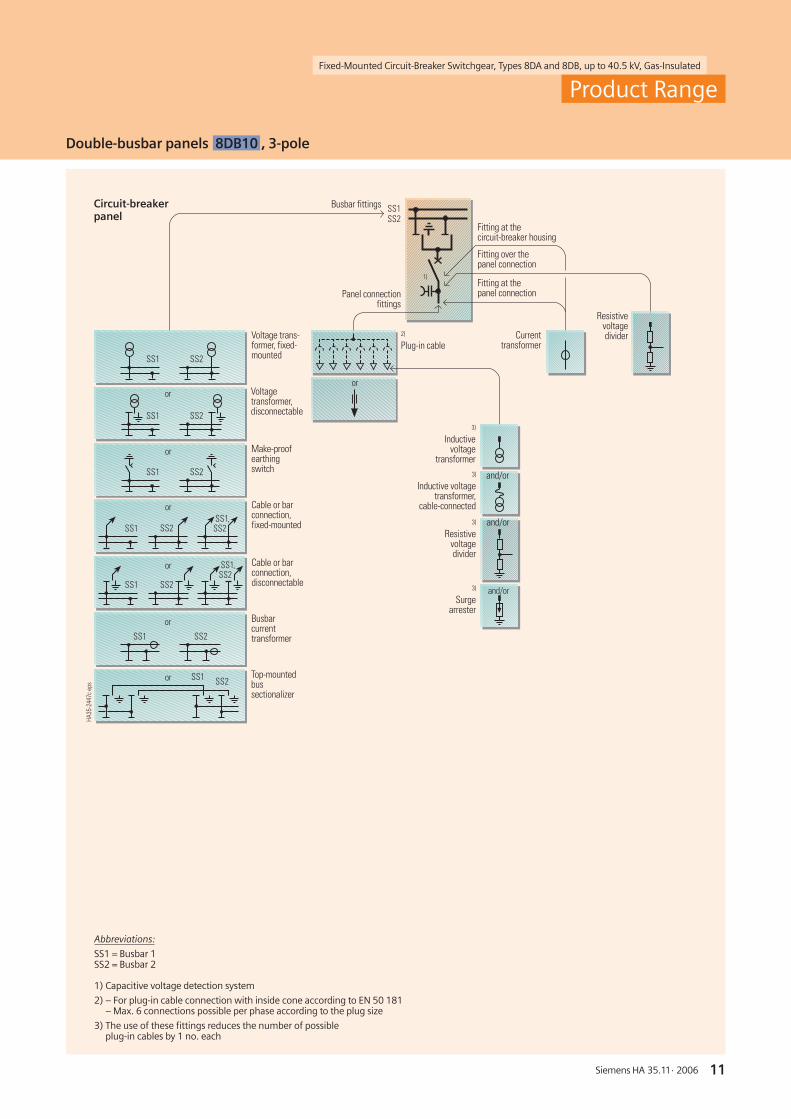
Double-busbar panels 8DB10 , 3-pole
Abbreviations:
SS1 = Busbar 1SS2 = Busbar 2
1) Capacitive voltage detection system
2) – For plug-in cable connection with inside cone according to EN 50 181– Max. 6 connections possible per phase according to the plug size
3) The use of these fittings reduces the number of possibleplug-in cables by 1 no. each
Circuit-breakerpanel
Busbar fittings
Panel connectionfittings
Fitting at thecircuit-breaker housing
Fitting over thepanel connection
Fitting at thepanel connection
1)
Voltage trans-former, fixed-mounted
Make-proofearthingswitch
Cable or barconnection,fixed-mounted
Top-mountedbussectionalizer
Busbarcurrenttransformer
Voltagetransformer,disconnectable
Cable or barconnection,disconnectable
Currenttransformer
Resistivevoltagedivider
3)
Inductivevoltage
transformer3)
Inductive voltagetransformer,
cable-connected
3)
Resistivevoltagedivider
3)
Surgearrester
and/or
and/or
and/or
2)
Plug-in cable
or
or
or
or
or
or
or
Fixed-Mounted Circuit-Breaker Switchgear, Types 8DA and 8DB, up to 40.5 kV, Gas-Insulated
12 Siemens HA 35.11· 2006
������
������
��� ���
��������
��� ���
����������� ���
��� ���
��� ���
��� ���
����������� �
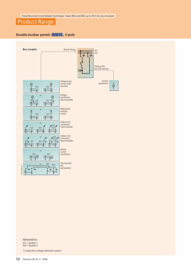
Bus coupler
Abbreviations:
SS1 = Busbar 1SS2 = Busbar 2
1) Capacitive voltage detection system
Busbar fittings
Fitting at thebus riser housing
1)
Voltage trans-former, fixed-mounted
Make-proofearthingswitch
Cable or barconnection,fixed-mounted
Top-mountedbussectionalizer
Busbarcurrenttransformer
Voltagetransformer,disconnectable
Cable or barconnection,disconnectable
Currenttransformer
or
or
or
or
or
or
Product Range
Double-busbar panels 8DB10 , 3-pole

Siemens HA 35.11· 2006
Fixed-Mounted Circuit-Breaker Switchgear, Types 8DA and 8DB, up to 40.5 kV, Gas-Insulated
13
���������� �
������
���
���
������������ �
������
���
���
Product Range
Double-busbar panels 8DB10 , 3-pole
Abbreviations:
SS1 = Busbar 1SS2 = Busbar 2
1) Capacitive voltage detection system
Bus sectionalizerfor busbar1 and 2Consisting of 2joined panels
Bus sectionalizerfor connection incable basementConsisting of 2separate panels
Busbar fittings
Fitting at thebus riser housing
Currenttransformer
or
or
Busbar currenttransformerat SS1
Busbar currenttransformerat SS2
Busbar currenttransformerat SS2
Busbar currenttransformerat SS1
Busbar fittings
Currenttransformer
Resistivevoltagedivider
Fitting at thecircuit-breaker housing
Fitting over thepanel connection
or
Panel connection fittings:Single plug-in cable,size 1 to 3, or bar(solid-insulated orgas-insulated)
Fitted in each panelat the connection ofthe circuit-breakeror the bus riser
1) 1)
1) 1) 1) 1)
Siemens HA 35.11· 2006
Fixed-Mounted Circuit-Breaker Switchgear, Types 8DA and 8DB, up to 40.5 kV, Gas-Insulated
14
����������� �
�
�
�
�
�
�
� ����������� �
����������� �
����������� �
�
�
�
�
�
�
�
�
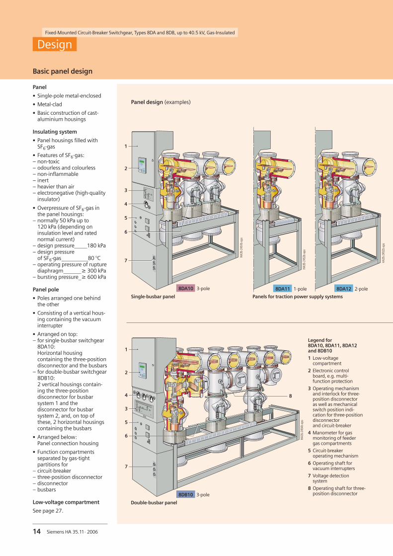
Basic panel design
Design
Panel
• Single-pole metal-enclosed
• Metal-clad
• Basic construction of cast-aluminium housings
Insulating system
• Panel housings filled withSF6-gas
• Features of SF6-gas:– non-toxic– odourless and colourless– non-inflammable– inert– heavier than air– electronegative (high-quality
insulator)
• Overpressure of SF6-gas inthe panel housings:
– normally 50 kPa up to120 kPa (depending oninsulation level and ratednormal current)
– design pressure 180 kPa– design pressure
of SF6-gas 80 °C– operating pressure of rupture
diaphragm ≥ 300 kPa– bursting pressure ≥ 600 kPa
Panel pole
• Poles arranged one behindthe other
• Consisting of a vertical hous-ing containing the vacuuminterrupter
• Arranged on top:– for single-busbar switchgear
8DA10:Horizontal housingcontaining the three-positiondisconnector and the busbars
– for double-busbar switchgear8DB10:2 vertical housings contain-ing the three-positiondisconnector for busbarsystem 1 and thedisconnector for busbarsystem 2, and, on top ofthese, 2 horizontal housingscontaining the busbars
• Arranged below:Panel connection housing
• Function compartmentsseparated by gas-tightpartitions for
– circuit-breaker– three-position disconnector– disconnector– busbars
Low-voltage compartment
See page 27.
Panel design (examples)
Double-busbar panel
Single-busbar panel Panels for traction power supply systems
Legend for8DA10, 8DA11, 8DA12and 8DB10
1 Low-voltagecompartment
2 Electronic controlboard, e.g. multi-function protection
3 Operating mechanismand interlock for three-position disconnectoras well as mechanicalswitch position indi-cation for three-positiondisconnectorand circuit-breaker
4 Manometer for gasmonitoring of feedergas compartments
5 Circuit-breakeroperating mechanism
6 Operating shaft forvacuum interrupters
7 Voltage detectionsystem
8 Operating shaft for three-position disconnector8DB10 3-pole
8DA12 2-pole8DA11 1-pole8DA10 3-pole

Siemens HA 35.11· 2006
Fixed-Mounted Circuit-Breaker Switchgear, Types 8DA and 8DB, up to 40.5 kV, Gas-Insulated
15
������������ �
��
��
�
�
������������ �
��
��
��
��
��
��
����������� �
�
�
�
�
�
�
�
�
����������� �
�
�
�
�
�
�
�
�
�
����
Basic panel design
Design
Single-pole design
Double busbar
1 Busbar housing
2 Busbar
3 Three-positiondisconnector
4 Gas-tight bushingbetween three-positiondisconnector andcircuit-breaker
5 Circuit-breaker housing
6 Vacuum interrupter
7 Current transformer
8 Pole supporting plate
9 Panel connectionSingle busbar
Items 1 to 9 as above
10 Gas-tight bushingbetween three-positiondisconnector or dis-connector and busbar 1
11 Gas-tight bushingbetween three-positiondisconnector (busbar 1)and disconnector(busbar 2)
12 Busbar disconnector forbusbar system 2
Gas compartment principle
• Optimal availability by means of– sealed pressure system– distribution of gas compartments– arrangement of manometers for
pressure monitoring– position of three-position
disconnectors
• Operation and monitoring of abusbar section only possible if allbusbar housings involved are ingood working order:
– operation and monitoring of theentire busbar section as one gascompartment is sufficient
– lining up individual panels to oneswitchgear assembly forms one gascompartment for each busbar phase
– manometer for this gas compart-ment mounted in one end wall
• Operation and monitoring of onebusbar section of a single-busbarswitchgear assembly also possibleif a feeder is faulty:
– “feeder” gas compartment separatedfrom “busbar” gas compartment
– 3 circuit-breaker housings intercon-nected by a pipe, ensuring individualgas monitoring for each panel
– manometer for this gas compart-ment mounted at the panel front
• Operation and monitoring of adouble-busbar switchgear also possi-ble if one busbar system or thedisconnector is faulty:
– gas compartments of both busbarsseparated from the gas compart-ments of both disconnectors
– 1 gas compartment available eachfor the 3 circuit-breaker housings,the disconnector housings and thethree-position disconnectorhousings
– 3 manometers mounted on the pa-nel front to monitor the gas pressure
• Separate, defined pressure relief foreach gas compartment
• Pressure monitoring via manometersin connection with alarm contactsto signal any increase or drop inpressure
• Ratings according to IEC 62 271-200resp. VDE 0671-200 remain un-changed after more than 20 yearsof operation. During this time, norefilling of SF6-gas will be necessary
Arrangementof gas compartments
Gas compartmentsof single-busbarswitchgear
Gas compartmentsof double-busbarswitchgear
1 Busbar: L12 Busbar: L23 Busbar: L3
4 Circuit-breaker
1 Busbar 1: L12 Busbar 1: L23 Busbar 1: L3
4 Busbar 2: L15 Busbar 2: L26 Busbar 2: L3
7 Busbar 1:Three-position disconnector
8 Busbar 2:Disconnector
9 Circuit-breaker
Siemens HA 35.11· 2006
Fixed-Mounted Circuit-Breaker Switchgear, Types 8DA and 8DB, up to 40.5 kV, Gas-Insulated
16
������������ �
������������ �
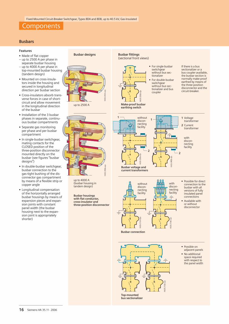
Busbars
Components
Features
• Made of flat copper– up to 2500 A per phase in
separate busbar housing– up to 4000 A per phase in
top-mounted busbar housing(tandem design)
• Mounted on cross-insula-tors inside the housing andsecured in longitudinaldirection per busbar section
• Cross-insulators absorb trans-verse forces in case of short-circuit and allow movementin the longitudinal directionof the busbar
• Installation of the 3 busbarphases in separate, continu-ous busbar compartments
• Separate gas monitoringper phase and per busbarcompartment
• In single-busbar switchgear,mating contacts for theCLOSED position of thethree-position disconnectormounted directly on thebusbar (see figures “busbardesigns”)
• In double-busbar switchgear,busbar connection to thegas-tight bushing of the dis-connector gas compartmentby means of a flexible strip orcopper angle
• Longitudinal compensationof the horizontally arrangedbusbar housings by means ofexpansion pieces and expan-sion joints with constantpanel width (the busbarhousing next to the expan-sion joint is appropriatelyshorter)
Busbar designs
Busbar housingswith flat conductor,cross-insulator andthree-position disconnector
up to 4000 A(busbar housing intandem design)
up to 2500 A
Busbar fittings(sectional front views)
1 Voltagetransformer
2 Currenttransformer
• Possible for directconnection to thebusbar with allversions of fullyinsulated panelconnections
• Available withor withoutdisconnector
• Possible onadjacent panels
• No additionalspace requiredwith respect tothe panel width
withdiscon-nectingfacility
������������ �
�
�
������������ �
�
� withoutdiscon-nectingfacility
Busbar voltage andcurrent transformers
Make-proof busbarearthing switch
������������ �
If there is a bussectionalizer or abus coupler available,the busbar section isnormally make-proofearthed by means ofthe three-positiondisconnector and thecircuit-breaker.
• For single-busbarswitchgearwithout bus sec-tionalizer
• For double-busbarswitchgearwithout bus sec-tionalizer and buscoupler
������������ �
Busbar connection
������������ �
withdiscon-nectingfacility
withoutdiscon-nectingfacility
����������� �
Top-mountedbus sectionalizer

Fixed-Mounted Circuit-Breaker Switchgear, Types 8DA and 8DB, up to 40.5 kV, Gas-Insulated
Siemens HA 35.11· 2006 17
������������ �
������������ �
������������ �
������������ �
Power consumption andprotection of the motor
Ratedvoltage
Rating
W
M.c.b. withC-characteristic
Rated current A
DC 60 V110 V220 V
100100100
31.60.5
AC 110 V220 V
100100
1.60.5
Rated power andoperating time of the interlocking magnet
Ratedvoltage
Rating
W
Operatingtime
%
60/110/220 V DC 7.1 100
110/220 V AC 7.1 100
R-HA
35-0
08ep
sR-
HA35
-009
eps
R-HA
35-0
10ep
sR-
HA35
-010
eps
Three-position disconnector
Components
Features
• Rated normal currents up to2500 A
• Up to 2000 operating cyclesfor the disconnector, 3000operating cycles for 8DA11/12switchgear
• Up to 1000 operating cyclesfor the earthing switch
• Operating shaft and contactblades with common centreof rotation and reliable switchposition up to the controlboard of the panel
• Maintenance-free
• Three switch positions– CLOSED: Contact blades
connected with the busbars:Main circuit closed betweenbusbar and circuit-breaker
– OPEN: Main circuit openbetween busbar and circuit-breaker: Test voltages for iso-lating distances are withstood
– READY-TO-EARTH:Contact blades connectedwith the earthing contact ofthe busbar housing: Feederearthed and short-circuited byclosing the circuit-breaker
• Gas-tight barriers separatethe busbar and circuit-breakerhousings from each other un-derneath the contact blades
• Cable connection and circuit-breaker housings can beremoved without interruptingbusbar operation.
Operating mechanism
• Only permissible operationspossible due to logicalmechanical interlocks
• Switch position indication viamechanically coupled flags
• Separate operating shafts forthe “Disconnecting” and“Ready-to-earth” functions
• Basically available withmanual or motor operatingmechanism
• Same sense of rotation forthe “CLOSE” or “OPEN” func-tions
• Logical mechanical interlocksfor double-busbar switchgearinterrogated by means of acontrol gate which selects thedisconnector to be operated(for busbar system 1 or 2).
Switch positionsfor three-positiondisconnector
Switch position indicationsfor three-position disconnectorand vacuum circuit-breaker
Feeder OFF
Feeder ON
Feeder READY-TO-EARTH
Feeder EARTHED
Electrical data for three-position disconnector and disconnector
Three-positiondisconnectorOPEN ( )
Vacuum circuit-breakerOPEN ( )
Three-positiondisconnectorCLOSED ( )
Vacuum circuit-breakerCLOSED ( )
Three-positiondisconnectorREADY-TO-EARTH
Vacuum circuit-breakerOPEN ( )
Three-positiondisconnectorEARTHED
Vacuum circuit-breakerCLOSED ( )
Siemens HA 35.11· 2006
Fixed-Mounted Circuit-Breaker Switchgear, Types 8DA and 8DB, up to 40.5 kV, Gas-Insulated
18
���������� �
�
�
����������� �
�
�
��
��
���
���
���
� ���
� ���
� ���
�� ���
�� ���
�� ���
��� ���
� � � �� �� �� ���
������������ �
������
�� ���
��
�� ��
��
��
���
���
���
� ���
� ���
� ���
�� ���
�� ���
�� ���
��� ���
� � � �� �� �� ���
����������� �
��
�� ���
��
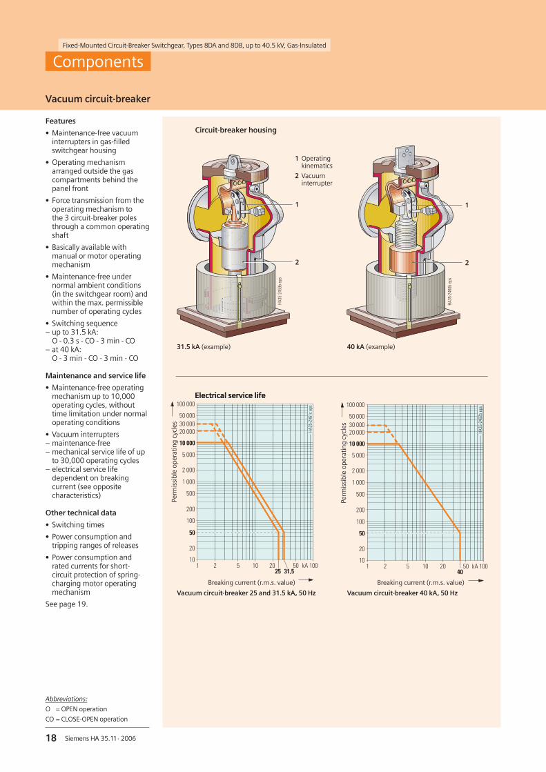
Vacuum circuit-breaker
Components
Features
• Maintenance-free vacuuminterrupters in gas-filledswitchgear housing
• Operating mechanismarranged outside the gascompartments behind thepanel front
• Force transmission from theoperating mechanism tothe 3 circuit-breaker polesthrough a common operatingshaft
• Basically available withmanual or motor operatingmechanism
• Maintenance-free undernormal ambient conditions(in the switchgear room) andwithin the max. permissiblenumber of operating cycles
• Switching sequence– up to 31.5 kA:
O - 0.3 s - CO - 3 min - CO– at 40 kA:
O - 3 min - CO - 3 min - CO
Maintenance and service life
• Maintenance-free operatingmechanism up to 10,000operating cycles, withouttime limitation under normaloperating conditions
• Vacuum interrupters– maintenance-free– mechanical service life of up
to 30,000 operating cycles– electrical service life
dependent on breakingcurrent (see oppositecharacteristics)
Other technical data
• Switching times
• Power consumption andtripping ranges of releases
• Power consumption andrated currents for short-circuit protection of spring-charging motor operatingmechanism
See page 19.
Circuit-breaker housing
Electrical service life
40 kA (example)31.5 kA (example)
1 Operatingkinematics
2 Vacuuminterrupter
Electrical service life
Breaking current (r.m.s. value) Breaking current (r.m.s. value)
Perm
issi
ble
oper
atin
gcy
cles
Perm
issi
ble
oper
atin
gcy
cles
Vacuum circuit-breaker 25 and 31.5 kA, 50 Hz Vacuum circuit-breaker 40 kA, 50 Hz
Abbreviations:
O = OPEN operation
CO = CLOSE-OPEN operation

Siemens HA 35.11· 2006
Fixed-Mounted Circuit-Breaker Switchgear, Types 8DA and 8DB, up to 40.5 kV, Gas-Insulated
19
Switching times
Designation Switching timeof vacuumcircuit-breakers
With the followingequipment
Closing time 1) 95 ± 10 ms –
Opening time 1) < 70 ms 1st shunt release
< 55 ms 2nd and 3rd release
< 25 ms Option:instantaneous release for 8DA11
Arcing time at 50 Hz < 15 ms –
Breaking time < 85 ms 1st shunt release
< 70 ms 2nd and 3rd release
Dead time 300 ms –
CLOSED/OPEN contact time < 80 ms 1st shunt release
< 65 ms 2nd and 3rd release
Minimum command duration 45 ms Closing solenoid
40 ms 1st shunt release
20 ms 2nd and 3rd release
Impulse time for circuit-breakertripping signal
> 15 ms 1st shunt release
> 10 ms 2nd and 3rd release
Charging time with elec. operation < 15 s –
Synchronism error between poles 2 ms –
Power consumption and rated currents for short-circuit protection of motors
Rated voltageof operatingmechanism
Operatingvoltagemax. min.
Power consumptionof motor
Smallest possible rated currentof m.c.b. withC-characteristic
DC 24 V48 V60 V
110 V220 V
26 V 20 V53 V 41 V66 V 51 V
121 V 93 V242 V 187 V
500 W500 W500 W500 W500 W
16 A8 A6 A3 A1.6 A
AC 110 V230 V
121 V 93 V244 V 187 V
650 VA650 VA
3 A1.6 A
Power consumption and tripping ranges of releases
Release Order No.ofrelease
Power consumption Tripping ranges
Operation
at DC at 50/60 Hz AC
Tripping voltage Trippingvoltageor current
atDC at 50/60 Hz AC
Closing solenoid 3AY15 10 140 W 140 VA 85 up to 110 % U 85 up to 110 % U
1st shunt release(without energy store)
3AY15 10 140 W 140 VA 70 up to 110 % U 85 up to 110 % U
2nd shunt release(with energy store)
3AX11 01 60 W 55 VA 70 up to 110 % U 85 up to 110 % U
Undervoltagerelease
3AX11 03 13 W 15 VA 35 up to 0 % U 35 up to 0 % U
Vacuum circuit-breaker
Other technical data
See opposite table
Components
1) Shorter switching times on request

Siemens HA 35.11· 2006
Fixed-Mounted Circuit-Breaker Switchgear, Types 8DA and 8DB, up to 40.5 kV, Gas-Insulated
20
1 Mounted on the busbar
2 Mounted on the circuit-breakerhousing
3 Mounted on the panel connection, possible for:– 1 to 3 cables per phase, interface type 2– 1 cable per phase, interface type 3 or 4– solid-insulated bar
4 Mounted on the cable
�
�
�
�
�
������������ �
Technical data for ring-core current transformers
Operating voltage max. 0.72 kV
Rated short-duration power-frequency withstand voltage
3 kV(winding test)
Rated frequency 50/60 Hz
Rated continuousthermal current
max. 1.2 x In
Rated thermalshort-time current
40 kA, max. 3 s
Rated dynamic current 100 kA
Rated primary current 40 up to 2500 A
Multiratio (secondary) 200 – 100 up to2500 – 1250 A
Rated secondary current 1 A or 5 A
Number of cores max. 3
Core data (according torated primary current):
Measuring Ratingcore Class
Overcurrent factorProtection Ratingcore Class
Overcurrent factor
2.5 up to 10 VA0.2 up to 1FS102.5 up to 30 VA5 up to 10P10 up to P30
Permissible ambienttemperature
max. 80 °C
Insulation class E
Standards IEC 60 044-1,VDE 0414-1
Components
Current transformers
Ring-core current transformers
• Ring-core as carrier ofsecondary winding
• Main circuit corresponds toprimary winding
• Arranged outside the primary enclosure(switchgear housing)
• Free of dielectrically stressed cast-resinparts (due to design)
• According to IEC 60 044-1 andVDE 0414-1
• Certifiable
Mounting locations
• At the busbar (1):Inside diameter of transformer 300 mm,max. overall height 155 mm
• At the circuit-breaker housing (2):Inside diameter of transformer 300 mm,max. overall height 294 mm
• At the panel connection (3):– with single connection up to interface
type 2:Inside diameter of transformer 180 mmand outside diameter of transformer376 mm, max. overall height 294 mm
– with single connection for interfacetype 3:Inside diameter of transformer 300 mm,max. overall height 294 mm
– with multiple connection(2 or 3 cable plugs interface type 2)per phase:Inside diameter of transformer 300 mm,max. overall height 214 mm
• On the cable (cable-type currenttransformer) (4)Depending on the cable
Mounting locationsfor ring-corecurrent transformers

Fixed-Mounted Circuit-Breaker Switchgear, Types 8DA and 8DB, up to 40.5 kV, Gas-Insulated
21Siemens HA 35.11· 2006
Technical data for low-power voltage transducers
Operating voltage max. 40.5 kV
Rated frequency 50/60 Hz
Secondary voltage 3.25 V/KL3
Accuracy 0.2 up to 0.5
Permissible ambienttemperature
max. 60 °C
Insulation class E
R-HA
35-0
80ep
s
Voltage transformer
• Cast-resin insulated
• Inductive type
• Safe-to-touch due to metalenclosure/metal coating
• Plug-in type
• Arranged outside theprimary enclosure (switch-gear housing)
• Mounting locations– at the busbar, metal-enclosed,
directly connected ordisconnectable through athree-position disconnector
– at the panel connection,metal-enclosed, directlyplugged in or mounted se-parately via a plug-in cable
• According to IEC 60 044-2 /VDE 0414-2
• Certifiable
Low-power voltagetransducers asresistor dividers
• According to IEC 60 044-7
• Mounted over the panel con-nection as flange dividers, orpluggable to any free socketas an inside-cone plug-insystem
• Suitable for all protection andmeasuring functions
• No ferroresonance possibleanymore
• No disconnection forswitchgear or cable tests
• Resistant against transientovervoltages
• Extended voltage measuringrange from 0.4 to 1.2 timesrated voltage
• High reliability and availa-bility
• Short-circuit-proof
• Rating-independent wiring
• System-conformity tonumerical secondary systems
Voltage transformers
Components
Mounting locations forinductive voltage transform-ers and low-power voltagetransducers
Low-power voltage transducer as resistor divider
Mounting location as above
for inside-cone plug-in system
������������ �
�
1 Mounted on the busbar,directly connected ordisconnectable through athree-position disconnector(figure)
Voltagetransfor-mer, dis-connect-able
�
������������ �
2 Mounted on the panelconnection, metal-enclosed,directly plugged in(figure) or mountedseparately via a plug-incable
Voltagetransformer,directlyplugged in(examplefor 36 kV)
Technical data for inductive voltage transformers
Operating voltage max. kV 12 24 36
Common data for inductive voltage transformers
Primary voltage kV 3.3/KL33.6/KL34.8/KL35.0/KL36.0/KL36.6/KL37.2/KL3
10.0/KL311.0/KL3
13.8/KL315.0/KL317.5/KL320.0/KL322.0/KL3
25.0/KL325.8/KL330.0/KL333.0/KL334.5/KL335.0/KL3
Secondary voltage V 100/KL3110/KL3
100/KL3110/KL3
100/KL3110/KL3
Busbar voltage transformer
Type 4MT32 4MT34 4MU1/4MT6
Auxiliary winding for Vearth-fault detection
100/3110/3
100/3110/3
100/3110/3
Secondary, thermal limit Acurrent of measuring winding
6 6 6
Rated voltage factor UN/8 h 1.9 1.9 1.9
Rated long-time current/8 h A 5 5 11
Accuracy 0.2/0.5/1 0.2/0.5/1 0.2/0.5/1
Rating VA 30/90/180 30/90/180 25/60/150
Voltage transformer, directly plugged in
Type 4MT72 4MT74 4MT76
Auxiliary winding for Vearth-fault detection
100/3110/3
100/3110/3
100/3110/3
Secondary, thermal limit Acurrent of measuring winding
7 7 6
Rated voltage factor UN/8 h 1.9 1.9 1.9
Rated long-time current/8 h A 6 6 6
Accuracy 0.2/0.5/1 0.2/0.5/1 0.2/0.5/1
Rating VA 10/30/75 10/30/75 10/30/75
Voltage transformer, mounted separately
Type 4MU32 4MU34 4MU36
Auxiliary winding for Vearth-fault detection
100/3110/3
100/3110/3
100/3110/3
Secondary, thermal limit Acurrent of measuring winding
6 6 6
Rated voltage factor UN/8 h 1.9 1.9 1.9
Rated long-time current/8 h A 6 6 6
Accuracy 0.2/0.5/1 0.2/0.5/1 0.2/0.5/1
Rating VA 30/90/180 30/90/180 30/90/180

Fixed-Mounted Circuit-Breaker Switchgear, Types 8DA and 8DB, up to 40.5 kV, Gas-Insulated
22 Siemens HA 35.11· 2006
Legend (pages 22 and 23)
1 Upper part of subframe
2 Lower part of subframe
3 Gas insulation
4 Floor of switchgear room
����� ��
�
����������� �
������ ����������� �
��
�
������ ����������� �
�
�
�
������ ���������� �
�
�
�
������ ����������� �
�
�
�
�
����� ����������� �
�
�
�
�
���� ����������� �
�
�
�
������ ����������� �
��
�
�
����� ����������� �
��
�
�
8DA10 8DA11/8DA12
Numberofcables
Forinterfacetype
1x 2
Numberofcables
Forinterfacetype
1x 3
Numberofcables
Forinterfacetype
1x 4
Numberofcables
Forinterfacetype
1xand 1x
23
Numberofcables
Forinterfacetype
2x 2
3x 2
Numberofcables
Forinterfacetype
2x 3
3x 3
2xand 1x
32
1xand 1x
32
Numberofcables
Forinterfacetype
1xand 1xand 1x
234
2xand 1x
24
1xand 1x
24
2xand 1x
34
1xand 1x
34
2x 4
Numberofcables
Forinterfacetype
6x 2
5x 2
4x 2
4xand 1x
23
3xand 1x
23
3xand 2x
23
2xand 2x
23
2xand 3x
23
1xand 3x
23
1xand 4x
23
4x 3
Numberofcables
Forinterfacetype
2x 2
2x 3
1xand 1x
23
Panel connection
Components
Features
• Fully insulated
• For inside-cone plug-in sys-tem according to EN 50 181
• For interface types 2, 3 and 4
• Interface types depending oncable cross-section and ratedvoltage
• Single and multiple connec-tions possible per phase, seeconnection drawings
• Multiple connections avail-able with different interfacetypes
• Solid-insulated or gas-insulated bar connection
• Number of possible cableconnections is reduced by 1
– if directly plugged in or sepa-rately mounted inductivevoltage transformers areconnected
– if plug-in surge arresters areconnected
Cable testing
Cable testing is possiblethrough an inside-cone socketby means of a test unit.
Panel connection for plug-in cables (possible versions)
Example: 2x interface type 2
Example: 2x interface type 3
Example:1x interface type 2 and1x interface type 3 and1x interface type 4
Example:2x interface type 2 and3x interface type 3
With plug-in voltagetransformer
Example: 1x interface type 2, 1x interface type 3,1x plug-in voltage transformer

Siemens HA 35.11· 2006
Fixed-Mounted Circuit-Breaker Switchgear, Types 8DA and 8DB, up to 40.5 kV, Gas-Insulated
23
����� ����������� �
��
�
������ ����������� �
��
�
����� ����������� �
�
�
�
������ ����������� �
�
�
�
������ ���������� �
��
�
�
8DB10���� ����������� �
�
�
�
�
�� � ����������� �
�
�
� ������ ����������� �
��
�
�
����� ����������� �
��
�
������ ����������� �
�
�
��
����� ����������� �
�
�
��
����� ����������� �
�
�
��
����� ����������� �
��
�
�
8DA10 8DA11/8DA12
8DB10
Numberofcables
Forinterfacetype
2x 2
2x 3
1xand 1x
23
Numberofcables
Forinterfacetype
6x 2
5x 2
4x 2
4xand 1x
23
3xand 1x
23
3xand 2x
23
2xand 2x
23
2xand 3x
23
1xand 3x
23
1xand 4x
23
4x 3
Numberofcables
Forinterfacetype
1xand 1xand 1x
234
2xand 1x
24
1xand 1x
24
2xand 1x
34
1xand 1x
34
2x 4
Numberofcables
Forinterfacetype
2x 3
3x 3
2xand 1x
32
1xand 1x
32
Example: 1x interface type 2, 1x interface type 3,1x plug-in voltage transformer
Panel connection
Components
Numberofcables
Forinterfacetype
1x 2
Numberofcables
Forinterfacetype
1x 3
Numberofcables
Forinterfacetype
1x 4
Numberofcables
Forinterfacetype
1xand 1x
23
Numberofcables
Forinterfacetype
2x 2
3x 2
Solid-insulated barfor rated normal currentsup to 2500 A
Gas-insulated barfor rated normal currentsup to 2500 A
Panelconnection for bar
Solid-insulated barfor rated normal currentsup to 2500 A
Gas-insulated barfor rated normal currentsup to 2500 A
Example: 2x interface type 3
Example:1x interface type 2 and1x interface type 3 and1x interface type 4
Example:2x interface type 2 and3x interface type 3
With plug-in voltagetransformerExample: 2x interface type 2

Fixed-Mounted Circuit-Breaker Switchgear, Types 8DA and 8DB, up to 40.5 kV, Gas-Insulated
24 Siemens HA 35.11· 2006
R-HA35-094.eps
1
2
3
10
1211
4
56
13
14
15
16
B
A
Control board
Components
Features
• Mechanical control boardlocated below the low-voltage compartment
• Actuation next to the operat-ing mechanisms
• Integrated mechanical switchposition indications in themimic diagram
• Unambiguous assignmentof actuating openings andcontrol elements to thecorresponding switch posi-tion indications
• Convenient height of allcontrol elements
Logical mechanical interlocks
• Internal panel interlocks areof the mechanical type
• Operation of three-positiondisconnector (disconnectingand earthing function) inter-locked with vacuum circuit-breaker in both directions
• Selector lock (4) opens orlocks the actuating openingsfor the disconnecting (3) andearthing function (2) in ac-cordance with the circuit-breaker position
• Actuating openings (2 and 3)cannot be opened with aselector key as long as thevacuum circuit-breaker isCLOSED
• Operating lever can be inser-ted in open actuating open-ings
• Operating lever cannot beremoved before the definiteend position of the discon-necting or earthing functionis reached – nor can theselector key
• Feeder de-earthing is securedby the vacuum circuit-breaker
– electrically via the auxiliaryswitch
– mechanically through thelever (13) of the mechanicalcircuit-breaker tripping block
A Operating mechanism forthree-position disconnector:
1 Switch position indicator CLOSED/OPENfor disconnecting function of three-positiondisconnector
2 Actuating opening for earthing function
3 Actuating opening for disconnectingfunction
4 Actuating opening for selector lock ofrespective switching operation
5 Switch position indicator CLOSED/OPEN forearthing function of three-positiondisconnector
6 Switch position indicator CLOSED/OPENfor vacuum circuit-breaker
7 Switch position indicator CLOSED/OPENfor 2nd disconnector in double-busbarswitchgear
8 Actuating opening for 2nd disconnector indouble-busbar switchgear
9 Control gate for selecting the three-positiondisconnector or the disconnector in double-busbar switchgear
B Operating mechanismfor vacuum circuit-breaker:
10 Mechanical ON pushbuttonfor vacuum circuit-breaker
11 Actuating opening for manual charging ofthe circuit-breaker operating spring
12 Mechanical OFF pushbuttonfor vacuum circuit-breaker
13 Lever for locking the vacuum circuit-breakeragainst de-earthing
14 Spring charged indicator
15 Switch position indicator CLOSED/OPENfor vacuum circuit-breaker
16 Operating cycle counterfor vacuum circuit-breaker
Operating mechanism for the three-positiondisconnector and the vacuum circuit-breaker
Control board forsingle-busbar panel 8DA10
Control board fordouble-busbar panel 8DB10
R-HA35-096a.eps
13
11
12
10
7
8
4
16
15
14
A
B
231
65
4 9

Fixed-Mounted Circuit-Breaker Switchgear, Types 8DA and 8DB, up to 40.5 kV, Gas-Insulated
25Siemens HA 35.11· 2006
R-HA
35-0
96ep
sR-
HA35
-094
eps
1
3
Indicating and measuring equipment
Components
Gas monitoring
• With contact manometer
• 2 signalling contacts for“pressure too low” and“pressure too high”
• Easy verification of readinessfor service by means ofred/green indication areas
• Local indication, also withoutauxiliary voltage
• Refilling socket for SF6-gaswith non-return valve andcover
• Number of manometers for8DA switchgear:
– 3 nos. for the busbar phases(1 no. per phase) of acomplete switchgear row,mounted in one of the twolateral end walls
– 1 no. for the 3 circuit-breakerpoles (mounted on the frontof each panel)
• Number of manometers for8DB switchgear:
– 6 nos. for the busbar phases(1 no. per phase and busbarsystem) of a completeswitchgear row, mounted inone of the two lateral endwalls
– 3 nos. for the switchpanelpoles;1 no. thereof for the3 circuit-breaker poles,1 no. for the 3 three-positiondisconnector poles of the firstbusbar system and1 no. for the 3 disconnectorpoles of the second busbarsystem (mounted on thefront of each panel)
Gas monitoring for 8DA switchgear(for single-busbar switchgear andtraction power supply systems)
Manometer (1) for circuit-breaker poles(mounted on the panel front)
Gas monitoring for 8DB switchgear(for double-busbar switchgear)
Manometer (2) forbusbar phases,mounted in the lateral endwall (side cover open)
Manometers (3) for circuit-breakerand disconnector poles(mounted on the panel front)
Manometer (4) forbusbar phases(mounted on the lateral end wall)
R-HA
35-0
97b
eps
4
R-HA
35-1
00a
eps
2

Fixed-Mounted Circuit-Breaker Switchgear, Types 8DA and 8DB, up to 40.5 kV, Gas-Insulated
26 Siemens HA 35.11· 2006
4 Voltage indicator,LRM system
Voltage detection systems
����������� ����
��� ��� ��
����
��
Voltage detectionvia capacitive voltage divider (principle)
–C1 Capacity coupling electrode integrated into bushing
–C2 Capacity of the coupling section (as well as connection leadsof the voltage detection system) to earth
ULE= UN / 3 during rated operation in the three-phase system
U2 = Voltage at the interface (for plug-in voltage detection system)or at the test socket (for integrated voltage detection system)
4
Voltage indicator, LRM system(inserted)
RHA4
0101
a.ep
s
plugged-inLRM system
mountedCAPDIS-S1+ or -S2+
CAPDIS-S1+ CAPDIS-S2+
A3
A4
A5
A6
Symbols shown on
A0 CAPDIS-S2+: Operating voltagenot present
A1 Operating voltage present
A2 – Operating voltage not present– For CAPDIS-S2+:
Auxiliary power not present
A3 Earth fault or failure in phase L1,operating voltage at L2 and L3
A4 Voltage (not operating voltage)present
A5 Indication “Device-function-test”passed
A6 Indication “ERROR”, e.g. in caseof missing auxiliary voltage(see: “error indication M4”)
������������ �
���� �� ���� ��
�����
A0
A1
A2
Indicating and measuring equipment
Components
Voltage detectionsystems
For voltage detectionaccording to IEC 61 243-5 /VDE 0682-415
• Detection systems(option):
– LRM system– Integrated voltage
detection systems,LRM system: CAPDIS-S1+and -S2+
LRM system
• With voltage indicator(LRM system)
• Verification of safe isola-tion from supply phaseby phase by insertion ineach socket pair
• Voltage indicator flasheswhen high voltage is pre-sent
• Indicator suitable forcontinuous operation
• Safe-to-touch
• Routine-tested
• Measuring system andvoltage indicator can betested
• Without auxiliary voltage
Features of integratedvoltage detection systems
Common features
• Maintenance-free
• Integrated display, withoutauxiliary power
• Integrated repeat test ofthe interfaces (self-testing)
• With integrated functiontest (without auxiliarypower) by pressing the“Device-function-test”pushbutton
• With integrated 3-phasetest socket for phase com-parison (also suitable forplug-in voltage indicator)
• Degree of protectionIP 54, temperature range–25 °C to +55 °C
• With circuit capacity
Features of CAPDIS-S1+
• Without auxiliary power
• With indication “A1” to “A5”(see legend)
• Without ready-for-servicemonitoring
• Without signalling relay(thus without auxiliarycontacts)
Features of CAPDIS-S2+
• With indication “A0” to “A6”(see legend)
• Only by pressing the“Device-function-test” push-button: “ERROR” indication(A6), e.g. in case of missingauxiliary voltage
• With ready-for-servicemonitoring (externalauxiliary power required)
• With integrated signallingrelay for signalling “M1” to“M4” (auxiliary powerrequired):
– “M1”: Operating voltagepresent at phases L1, L2, L3
– “M2”: Voltage not presentat L1, L2 and L3(= active zero indication)
– “M3”: Earth fault or voltagefailure, e.g. in one phase
– “M4”: External auxiliarypower missing (operatingvoltage present or not)
• Separate circuit capacity

Fixed-Mounted Circuit-Breaker Switchgear, Types 8DA and 8DB, up to 40.5 kV, Gas-Insulated
27Siemens HA 35.11· 2006
R-HA
35-0
94ep
s
Low-voltage equipment
Components
Low-voltage compartment
• Accommodates equipmentfor protection, control,measuring and metering
• Separated from thehigh-voltage part,safe-to-touch
• Low-voltage compartmentcan be removed, bus wiresand control cables areplugged in
• Option: High low-voltagecompartment (1200 mm)possible
Description ofthe SIPROTEC 4multifunctionprotection relays,see page 28.
Low-voltage compartment with multifunctionprotection relay SIPROTEC 4 7SJ61 (example)

Fixed-Mounted Circuit-Breaker Switchgear, Types 8DA and 8DB, up to 40.5 kV, Gas-Insulated
28 Siemens HA 35.11· 2006
4
5
6
2
3
R-HA
35-1
02ep
sR-
HA35
-104
eps
R-HA
35-1
03ep
s
1
7
2
6
4
4
2
7
Low-voltage equipment
Components
Multifunction protectionrelay SIPROTEC 4 7SJ63
• For stand-alone or masteroperation
• Communications and buscapability
• Functions: control,protection, indicating,communications andmeasuring
• LCD for process andequipment data, in theform of a feeder mimicdiagram and as text, e.g.for
– measuring and meteringvalues
– information on status ofswitchgear and switchingdevice
– protection data– general indications– alarms
• Four user-programmablefunction keys for fre-quently performedactions
• Fourteen user-program-mable LEDs for displayingany desired data
• Two key-operated swit-ches to switch between“local and remote con-trol” and “interlocked andnon-interlocked opera-tion”
• Keys for navigation inmenus and for enteringvalues
• Integrated motor controlby special relays withenhanced performance
Multifunction protectionrelay SIPROTEC 47SJ600/7SJ602
• User-friendly operatingprogram DIGSI 4 for con-figuration and analysis
• Communications and buscapability
• Functions: control,protection, indicating,communications andmeasuring
• LCD (2 text lines) andkeyboard for local opera-tion, configuration anddisplay
• Four user-programmableLEDs for displaying anydesired data
• Operation and faultindication memory
• Fault recording
• Circuit-breaker control
Multifunction protectionrelay SIPROTEC 47SJ61/7SJ62
• For stand-alone or masteroperation
• Communications and buscapability
• Functions: control,protection, indicating,communications andmeasuring
• LCD (4 text lines) for pro-cess and equipment data,in the form of a feedermimic diagram and astext, e.g. for
– measuring and meteringvalues
– information on status ofswitchgear and switchingdevice
– protection data– general indications– alarms
• Four user-programmablefunction keys forfrequently performedactions
• Seven user-program-mable LEDs for displayingany desired data
• Keys for navigation inmenus and for enteringvalues
Legend
1 LCD
2 LEDs
3 Key-operated switches
4 Navigation keys
5 Control keys
6 Function keys
7 LCD (text display)
Multifunction protection relays SIPROTEC 4
Multifunction protection relaySIPROTEC 4 7SJ600/7SJ602
Multifunction protection relaySIPROTEC 4 7SJ61/7SJ62
Multifunction protectionrelay SIPROTEC 4 7SJ63

Fixed-Mounted Circuit-Breaker Switchgear, Types 8DA and 8DB, up to 40.5 kV, Gas-Insulated
29Siemens HA 35.11· 2006 29
Overview of standards (January 2006)
IEC standard VDE standard EN standard
Switchgear 8DA, 8DB IEC 60 694 VDE 0670-1000 EN 60 694
IEC 62 271-200 VDE 0671-200 EN 62 271-200
Devices Circuit-breaker IEC 62 271-100 VDE 0671-100 EN 62 271-100
Vacuum contactor IEC 60 470 VDE 0670-501 EN 60 470
Disconnector and earthingswitch
IEC 62 271-102 VDE 0671-102 EN 62 271-102
Switch-disconnector IEC 62 265-1 VDE 0670-301 EN 60 265-1
Switch-disconnector /fuse combination
IEC 62 271-105 VDE 0671-105 EN 62 271-105
HV HRC fuses IEC 60 282 VDE 0670-4 EN 60 282
Voltage detection systems IEC 61 243-5 VDE 0682-415 EN 61 243-5
Degree ofprotection
IEC 60 529 VDE 0470-1 EN 60 529
Insulation IEC 60 071 VDE 0111 EN 60 071
Transformers Current transformers IEC 60 044-1 VDE 0414-1 EN 60 044-1
Voltage transformers IEC 60 044-2 VDE 0414-2 EN 60 044-2
Current-carrying capacity
• According to IEC 62 271-200or IEC 60 694 andVDE 0671-200 orVDE 0670-1000, current-carrying capacities refer tothe following ambient tem-peratures:
– maximum of24-hour mean + 35 °C
– maximum + 40 °C
• The current-carrying capacityof the panels and busbarsdepends on the ambienttemperature outside theenclosure.
Site altitude
The gas insulation permitsinstallation of the switchgear atany altitude above sea levelwithout influences on thedielectric strength. This alsoapplies to cable connection.
Overview of standards for traction applications
IEC standard EN standard
Supply voltage IEC 60 850 EN 50 163
Switchgear – EN 50 152
Insulation – EN 50 124
Standards, specifications, guidelines
Standards
Standards
The 8DA/8DB switchgearcomplies with the relevantstandards and specificationsapplicable at the time of thetype tests.
In accordance with the harmo-nization agreement reachedby the EU countries, theirnational specificationsconform to the IEC standard.
Type of service location
8DA/8DB switchgear can beused as an indoor installation inaccordance with VDE 0101 orthe Harmonization DocumentHD 637 S1 (Power installationsexceeding 1 kV AC)
• Outside lockable electrical ser-vice locations at places whichare not accessible to the pub-lic. Enclosures of switchgearcan only be removed withtools.
• Inside lockable electricalservice locations. A lockableelectrical service location is aplace outdoors or indoors thatis reserved exclusively forhousing electrical equipmentand which is kept under lockand key. Access is restricted toauthorized personnel andpersons who have been prop-erly instructed in electricalengineering. Untrained orunskilled persons may onlyenter under the supervisionof authorized personnel orproperly instructed persons.
Aseismic capacity (option)
• 8DA/8DB switchgear can beupgraded for regions at riskfrom earthquakes.
For upgrading, earthquakequalification testing is carriedout in accordance with thefollowing standards:
• IEC 68-3-3 1993
• IEC 68-2-6 1995
• IABG TA13-TM-002/98(guide)
Within the range of the prevail-ing earthquake frequenciesfrom 1 Hz to 35 Hz, the category1 required response spectrumto IABG TA13-TM-002/98 coversthe following response spectra:
• Uniform BuildingCode zone 3
• Seismic RequirementsSpec. 9067; Department ofWater & Power, Los Angeles
• GTS – 1.013 ENDESA, Chile
• VDE 0670-111
Insulating capacity
• The insulating capacity is veri-fied by testing the switchgearat rated short-duration power-frequency withstand voltageand rated lightning impulsewithstand voltage in accord-ance with IEC 60 694 andVDE 0671-1000(see following table).
• The rated values refer to sealevel and to normal atmos-pheric conditions (1013 hPa,20 °C, 11 g/m3 water contentin accordance with IEC 60 071and VDE 0111).
• With increasing altitude, theinsulating capacity decreases.This influence can be neglec-ted for gas-insulated switch-gear 8DA/8DB.
Table – Insulating capacity
Rated voltage (r.m.s. value) kV 7.2 12 15 17.5 24 36 38 40.5 40.5
Rated short-duration power-frequency withstand voltage (r.m.s. value)
– across isolating distance kV 23 32 39 45 60 80 90 90 110
– between phases and to earth kV 20 28 35 38 50 70 80 85 95
Rated lightning impulse withstand voltage (peak value)
– across isolating distance kV 70 85 105 110 145 195 230 218 218
– between phases and to earth kV 60 75 95 95 125 170 200 185 185

Fixed-Mounted Circuit-Breaker Switchgear, Types 8DA and 8DB, up to 40.5 kV, Gas-Insulated
30 Siemens HA 35.11· 200630
Internal arc classification
Standards, specifications, guidelines
Standards
Internal arc fault test
• Tests for verifying the internalarc classification should es-tablish proper protection foroperating personnel
• The tests must be per-formed in accordance withIEC 62 271-200/VDE 0671-200
Criteria for internal arc faults
• Criteria according toIEC 62 271-200/VDE-0671-200with respect to thebehaviour in case of internalarc faults
• Definitions of criteria:– Acceptance criterion 1
Covers and doors remainclosed. Limited deformationsare accepted
– Acceptance criterion 2No fragmentation of theenclosure. No projection ofsmall parts above 60 g weight
– Acceptance criterion 3No holes in the accessiblesides up to a height of 2 m
– Acceptance criterion 4Indicators do not ignite due tothe effect of hot gases
– Acceptance criterion 5The enclosure remainsconnected to its earthingparts
Climate andambient conditions
8DA/8DB indoor switchgear arehighly insensitive to climateand ambient conditions due tothe following features:
• Gas insulation of all high-voltage parts (no negativeeffects on the primary part ofthe switchgear)
• No cross-insulation of isolat-ing distances from phase tophase
• Bearings in operating mecha-nisms are designed as drybearings
• Operating mechanism partswhich are functionally impor-tant are made of corrosion-resistant materials
• Insensitive to ambient effectssuch as
– natural foreign bodies– chemically active pollutants– small animals and insects
Additional safety
• No short-circuit arcingbetween phases due tosingle-pole metal enclosure
• Earth-fault arcing betweenphase and earthed enclosureharmless due to
– low current arcs incompensated and insulatedsystems
– no important damages toinsulation, main circuits andmetal enclosure
• In effectively or resistivelyearthed systems the partitionbushings restrict the effects ofarc faults to the gas compart-ment affected (adjacent polesare not affected)
• Any excess pressure is relievedby means of rupture dia-phragms: the aluminium en-closure does not tear open
• Probability of arcingconsiderably lower than inair-insulated switchgear asthere are no effects due to
– pollution layers– moisture– small animals and foreign
bodies
• Maloperation is practically ex-cluded by logical arrangementof operating elements andlogical mechanical interlocks
• Short-circuit-proof feederearthing by means of three-position disconnector in com-bination with vacuum circuit-breaker

Fixed-Mounted Circuit-Breaker Switchgear, Types 8DA and 8DB, up to 40.5 kV, Gas-Insulated
31Siemens HA 35.11· 2006 31
Type of protection Degree of protection
I P 3 X Dsss
Protection against solid foreign bodiesProtected against ingress of solid foreign bodies,diameter W 2.5 mm (probe with diameter 2.5 mmmust not ingress)
Protection against waterNo specification
Protection against electric shockProtected against access to hazardousparts with a wire (probe with diameter 1 mm,length 100 mm must be sufficientlyclear of hazardous parts)
I P 6 5ss
Protection against solid foreign bodiesDust-tight: No ingress of dust
Protection against electric shockProtected against access to hazardousparts with a wire(probe with diameter 1 mm must not ingress)
Protection against waterProtected against water jets;water directed against the enclosure fromany direction in the form of a jet mustnot have any harmful effect
I P 3 1 Dsss
Protection against solid foreign bodiesProtected against ingress of solid foreign bodies,diameter W 2.5 mm (probe with diameter 2.5 mmmust not ingress)
Protection against waterProtected against dripping water(vertically falling drops must nothave any harmful effect)
Protection against electric shockProtected against access to hazardousparts with a wire (probe with diameter 1 mm,length 100 mm must be sufficientlyclear of hazardous parts)
Standards, specifications, guidelines
Standards
Protection against solid for-eign bodies, electric shockand water
8DA/8DB switchgear compliesaccording to
with the following degrees ofprotection:
See adjacent table forexplanations about the degreesof protection
Degree ofprotection
Type ofprotection
IP 3XD for outerenclosure
IP 65 for all partsunder highvoltage
IP 31D(option)
for low-voltagecompartment
Notes
If not stated otherwise on theindividual pages of this catalog,we reserve the right to includemodifications, especiallyregarding the stated values,dimensions and weights.
Drawings are not binding.
All product designations usedare trademarks or productnames of Siemens AG or othersuppliers.
If not stated otherwise, alldimensions in this catalog aregiven in mm.
The information in thisdocument contains generaldescriptions of the technicaloptions available, which donot always have to be presentin individual cases.The required features shouldtherefore be specified in eachindividual case at the time ofclosing the contract.
Some of the figuresshown feature customer-specific constructions.
Responsible for
Technical contents:Stefan AuxelSiemens AG, Dept. PTD M 2 PPMErlangen
General editing:Gabriele PollokSiemens AG, Dept. PTD CC MErlangen
Printed in GermanyKGK 01.06 6.0 28 En 1015506101/C6037
IEC 60529 and EN 60529:
IEC 60 694 VDE 0670-1000EN 60 694
IEC 60 529 EN 60 529
IEC 62 271-200 VDE 0671-200

Order No.: E50001-K1435-A101-A9-7600www.siemens.com/medium-voltage-switchgear
Published by
Siemens AG
Power Transmission and DistributionMedium Voltage DivisionPostfach 32 40
91050 ErlangenGermany
If you have any questions aboutPower Transmission and Distribution,our Customer Support Centeris available around the clock
Tel.: +49 180 / 524 70 00Fax: +49 180 / 524 24 71
E-Mail: [email protected]/energy-support
(Subject to charges,e.g.: 12 ct/min.)