medium voltage onegear smc flex motor controller...
TRANSCRIPT

Medium Voltage OneGear SMC Flex Motor Controller (10…15 kV)Catalog Numbers 7760, 7761, 7762, 7763
User ManualOriginal Instructions

Important User Information
Read this document and the documents listed in the additional resources section about installation, configuration, and operation of this equipment before you install, configure, operate, or maintain this product. Users are required to familiarize themselves with installation and wiring instructions in addition to requirements of all applicable codes, laws, and standards.
Activities including installation, adjustments, putting into service, use, assembly, disassembly, and maintenance are required to be carried out by suitably trained personnel in accordance with applicable code of practice.
If this equipment is used in a manner not specified by the manufacturer, the protection provided by the equipment may be impaired.
In no event will Rockwell Automation, Inc. be responsible or liable for indirect or consequential damages resulting from the use or application of this equipment.
The examples and diagrams in this manual are included solely for illustrative purposes. Because of the many variables and requirements associated with any particular installation, Rockwell Automation, Inc. cannot assume responsibility or liability for actual use based on the examples and diagrams.
No patent liability is assumed by Rockwell Automation, Inc. with respect to use of information, circuits, equipment, or software described in this manual.
Reproduction of the contents of this manual, in whole or in part, without written permission of Rockwell Automation, Inc., is prohibited
Throughout this manual, when necessary, we use notes to make you aware of safety considerations.
Labels may also be on or inside the equipment to provide specific precautions.
WARNING: Identifies information about practices or circumstances that can cause an explosion in a hazardous environment, which may lead to personal injury or death, property damage, or economic loss.
ATTENTION: Identifies information about practices or circumstances that can lead to personal injury or death, property damage, or economic loss. Attentions help you identify a hazard, avoid a hazard, and recognize the consequence.
IMPORTANT Identifies information that is critical for successful application and understanding of the product.
SHOCK HAZARD: Labels may be on or inside the equipment, for example, a drive or motor, to alert people that dangerous voltage may be present.
BURN HAZARD: Labels may be on or inside the equipment, for example, a drive or motor, to alert people that surfaces may reach dangerous temperatures.
ARC FLASH HAZARD: Labels may be on or inside the equipment, for example, a motor control center, to alert people to potential Arc Flash. Arc Flash will cause severe injury or death. Wear proper Personal Protective Equipment (PPE). Follow ALL Regulatory requirements for safe work practices and for Personal Protective Equipment (PPE).

Table of Contents
Summary of Changes New and Updated Information . . . . . . . . . . . . . . . . . . . . . . . . . . . . . . . . . . . . . 9
Preface Service Procedure . . . . . . . . . . . . . . . . . . . . . . . . . . . . . . . . . . . . . . . . . . . . . . . . 11
Chapter 1Product Overview Manual Objectives . . . . . . . . . . . . . . . . . . . . . . . . . . . . . . . . . . . . . . . . . . . . . . . 13
Documentation . . . . . . . . . . . . . . . . . . . . . . . . . . . . . . . . . . . . . . . . . . . . . . . . . . 13Description. . . . . . . . . . . . . . . . . . . . . . . . . . . . . . . . . . . . . . . . . . . . . . . . . . . . . . 13
7703 – OEM Controller . . . . . . . . . . . . . . . . . . . . . . . . . . . . . . . . . . . . . . 137760 – Retrofit Controller . . . . . . . . . . . . . . . . . . . . . . . . . . . . . . . . . . . . 147761 – Combination Controller. . . . . . . . . . . . . . . . . . . . . . . . . . . . . . . 157762 – Combination Controller (Vacuum Contactor) . . . . . . . . . . 167763 – Combination Controller (Vacuum Breaker) . . . . . . . . . . . . . 17Power Factor Correction Capacitors . . . . . . . . . . . . . . . . . . . . . . . . . . . 18Proposal for Implementation of Power Factor Correction Capacitors 20SMC Flex Control Module. . . . . . . . . . . . . . . . . . . . . . . . . . . . . . . . . . . . 21
Starting Modes . . . . . . . . . . . . . . . . . . . . . . . . . . . . . . . . . . . . . . . . . . . . . . . . . . 22Soft Start . . . . . . . . . . . . . . . . . . . . . . . . . . . . . . . . . . . . . . . . . . . . . . . . . . . . 22Selectable Kickstart . . . . . . . . . . . . . . . . . . . . . . . . . . . . . . . . . . . . . . . . . . . 23Current Limit Start. . . . . . . . . . . . . . . . . . . . . . . . . . . . . . . . . . . . . . . . . . . 23Dual Ramp Start . . . . . . . . . . . . . . . . . . . . . . . . . . . . . . . . . . . . . . . . . . . . . 24Full Voltage Start. . . . . . . . . . . . . . . . . . . . . . . . . . . . . . . . . . . . . . . . . . . . . 24Preset Slow Speed . . . . . . . . . . . . . . . . . . . . . . . . . . . . . . . . . . . . . . . . . . . . 25Linear Speed Acceleration and Deceleration . . . . . . . . . . . . . . . . . . . . 26Soft Stop . . . . . . . . . . . . . . . . . . . . . . . . . . . . . . . . . . . . . . . . . . . . . . . . . . . . 27
Protection and Diagnostics . . . . . . . . . . . . . . . . . . . . . . . . . . . . . . . . . . . . . . . 28Overload . . . . . . . . . . . . . . . . . . . . . . . . . . . . . . . . . . . . . . . . . . . . . . . . . . . . 28Underload . . . . . . . . . . . . . . . . . . . . . . . . . . . . . . . . . . . . . . . . . . . . . . . . . . . 30Undervoltage . . . . . . . . . . . . . . . . . . . . . . . . . . . . . . . . . . . . . . . . . . . . . . . . 30Overvoltage . . . . . . . . . . . . . . . . . . . . . . . . . . . . . . . . . . . . . . . . . . . . . . . . . . 30Unbalance . . . . . . . . . . . . . . . . . . . . . . . . . . . . . . . . . . . . . . . . . . . . . . . . . . . 31Stall Protection and Jam Detection . . . . . . . . . . . . . . . . . . . . . . . . . . . . 31Ground Fault . . . . . . . . . . . . . . . . . . . . . . . . . . . . . . . . . . . . . . . . . . . . . . . . 32Thermistor/PTC Protection . . . . . . . . . . . . . . . . . . . . . . . . . . . . . . . . . . 33PTC Trip. . . . . . . . . . . . . . . . . . . . . . . . . . . . . . . . . . . . . . . . . . . . . . . . . . . . 34Open Gate . . . . . . . . . . . . . . . . . . . . . . . . . . . . . . . . . . . . . . . . . . . . . . . . . . . 34Line Faults . . . . . . . . . . . . . . . . . . . . . . . . . . . . . . . . . . . . . . . . . . . . . . . . . . . 35Excessive Starts/Hour . . . . . . . . . . . . . . . . . . . . . . . . . . . . . . . . . . . . . . . . 35Overtemperature . . . . . . . . . . . . . . . . . . . . . . . . . . . . . . . . . . . . . . . . . . . . . 35
Metering . . . . . . . . . . . . . . . . . . . . . . . . . . . . . . . . . . . . . . . . . . . . . . . . . . . . . . . . 36I/O . . . . . . . . . . . . . . . . . . . . . . . . . . . . . . . . . . . . . . . . . . . . . . . . . . . . . . . . . . . . . 36Communication . . . . . . . . . . . . . . . . . . . . . . . . . . . . . . . . . . . . . . . . . . . . . . . . . 37Programming . . . . . . . . . . . . . . . . . . . . . . . . . . . . . . . . . . . . . . . . . . . . . . . . . . . . 37Status Indication . . . . . . . . . . . . . . . . . . . . . . . . . . . . . . . . . . . . . . . . . . . . . . . . . 38
Rockwell Automation Publication 7760-UM001F-EN-P - March 2016 3

Table of Contents
Control Options . . . . . . . . . . . . . . . . . . . . . . . . . . . . . . . . . . . . . . . . . . . . . . . . . 39Pump Control Option . . . . . . . . . . . . . . . . . . . . . . . . . . . . . . . . . . . . . . . . 39Pump Application Considerations . . . . . . . . . . . . . . . . . . . . . . . . . . . . . 39Braking Control Options . . . . . . . . . . . . . . . . . . . . . . . . . . . . . . . . . . . . . 40
Hardware Description. . . . . . . . . . . . . . . . . . . . . . . . . . . . . . . . . . . . . . . . . . . . 40Power Module . . . . . . . . . . . . . . . . . . . . . . . . . . . . . . . . . . . . . . . . . . . . . . . 41Current Loop Gate Driver (CLGD) Board . . . . . . . . . . . . . . . . . . . . . 41Interface Board. . . . . . . . . . . . . . . . . . . . . . . . . . . . . . . . . . . . . . . . . . . . . . . 41
Functional Description . . . . . . . . . . . . . . . . . . . . . . . . . . . . . . . . . . . . . . . . . . . 44Bulletin 7763 – Basic Control – Controlled Start only . . . . . . . . . . 44Bulletin 7760 – Basic Control – Controlled Start Only. . . . . . . . . . 44
Chapter 2Commissioning Procedure Preliminary Setup . . . . . . . . . . . . . . . . . . . . . . . . . . . . . . . . . . . . . . . . . . . . . . . . 47
System Characteristics . . . . . . . . . . . . . . . . . . . . . . . . . . . . . . . . . . . . . . . . . . . . 48Actual Motor Load . . . . . . . . . . . . . . . . . . . . . . . . . . . . . . . . . . . . . . . . . . . 48
Important Commissioning Checks . . . . . . . . . . . . . . . . . . . . . . . . . . . . . . . . 49Programming . . . . . . . . . . . . . . . . . . . . . . . . . . . . . . . . . . . . . . . . . . . . . . . . . . . . 50
MV SMC Flex Module . . . . . . . . . . . . . . . . . . . . . . . . . . . . . . . . . . . . . . . 50Hi-Pot and Megger Test . . . . . . . . . . . . . . . . . . . . . . . . . . . . . . . . . . . . . . . . . . 50Resistance Checks and Power Supply Tests . . . . . . . . . . . . . . . . . . . . . . . . . 53Control Function Tests. . . . . . . . . . . . . . . . . . . . . . . . . . . . . . . . . . . . . . . . . . . 58Voltage Sensing Module . . . . . . . . . . . . . . . . . . . . . . . . . . . . . . . . . . . . . . . . . . 58Start-Up. . . . . . . . . . . . . . . . . . . . . . . . . . . . . . . . . . . . . . . . . . . . . . . . . . . . . . . . . 59
Chapter 3Programming Overview . . . . . . . . . . . . . . . . . . . . . . . . . . . . . . . . . . . . . . . . . . . . . . . . . . . . . . . . 61
Keypad Description . . . . . . . . . . . . . . . . . . . . . . . . . . . . . . . . . . . . . . . . . . . . . . 61Programming Menu . . . . . . . . . . . . . . . . . . . . . . . . . . . . . . . . . . . . . . . . . . . . . . 61Password . . . . . . . . . . . . . . . . . . . . . . . . . . . . . . . . . . . . . . . . . . . . . . . . . . . . . . . . 65Parameter Management . . . . . . . . . . . . . . . . . . . . . . . . . . . . . . . . . . . . . . . . . . 66
Random Access Memory (RAM) . . . . . . . . . . . . . . . . . . . . . . . . . . . . . . 66Read-only Memory (ROM) . . . . . . . . . . . . . . . . . . . . . . . . . . . . . . . . . . . 66Electrically Erasable Programmable Read-only Memory (EEPROM) 67
Parameter Modification . . . . . . . . . . . . . . . . . . . . . . . . . . . . . . . . . . . . . . . . . . 67Soft Start . . . . . . . . . . . . . . . . . . . . . . . . . . . . . . . . . . . . . . . . . . . . . . . . . . . . . . . . 68Current Limit Start . . . . . . . . . . . . . . . . . . . . . . . . . . . . . . . . . . . . . . . . . . . . . . 68Dual Ramp Start . . . . . . . . . . . . . . . . . . . . . . . . . . . . . . . . . . . . . . . . . . . . . . . . . 69Full Voltage Start . . . . . . . . . . . . . . . . . . . . . . . . . . . . . . . . . . . . . . . . . . . . . . . . 70Linear Speed . . . . . . . . . . . . . . . . . . . . . . . . . . . . . . . . . . . . . . . . . . . . . . . . . . . . . 70Stop Control . . . . . . . . . . . . . . . . . . . . . . . . . . . . . . . . . . . . . . . . . . . . . . . . . . . . 70Preset Slow Speed . . . . . . . . . . . . . . . . . . . . . . . . . . . . . . . . . . . . . . . . . . . . . . . . 71Basic Set-up . . . . . . . . . . . . . . . . . . . . . . . . . . . . . . . . . . . . . . . . . . . . . . . . . . . . . 71Motor Protection . . . . . . . . . . . . . . . . . . . . . . . . . . . . . . . . . . . . . . . . . . . . . . . . 73Example Settings . . . . . . . . . . . . . . . . . . . . . . . . . . . . . . . . . . . . . . . . . . . . . . . . . 74
Undervoltage . . . . . . . . . . . . . . . . . . . . . . . . . . . . . . . . . . . . . . . . . . . . . . . . 74
4 Rockwell Automation Publication 7760-UM001F-EN-P - March 2016

Table of Contents
Overvoltage(1) . . . . . . . . . . . . . . . . . . . . . . . . . . . . . . . . . . . . . . . . . . . . . . . . 74Jam . . . . . . . . . . . . . . . . . . . . . . . . . . . . . . . . . . . . . . . . . . . . . . . . . . . . . . . . . . 74Underload(2) . . . . . . . . . . . . . . . . . . . . . . . . . . . . . . . . . . . . . . . . . . . . . . . . . 74
Motor Information . . . . . . . . . . . . . . . . . . . . . . . . . . . . . . . . . . . . . . . . . . . . . . . 75Motor Data Entry . . . . . . . . . . . . . . . . . . . . . . . . . . . . . . . . . . . . . . . . . . . . . 75
Chapter 4Metering Overview. . . . . . . . . . . . . . . . . . . . . . . . . . . . . . . . . . . . . . . . . . . . . . . . . . . . . . . . . 77
Viewing Metering Data. . . . . . . . . . . . . . . . . . . . . . . . . . . . . . . . . . . . . . . . . . . . 77
Chapter 5Options Overview. . . . . . . . . . . . . . . . . . . . . . . . . . . . . . . . . . . . . . . . . . . . . . . . . . . . . . . . . 79
Human Interface Module . . . . . . . . . . . . . . . . . . . . . . . . . . . . . . . . . . . . . . . . . 79Programming Parameters . . . . . . . . . . . . . . . . . . . . . . . . . . . . . . . . . . . . . . . . . . 81Control Wiring. . . . . . . . . . . . . . . . . . . . . . . . . . . . . . . . . . . . . . . . . . . . . . . . . . . 82
Chapter 6Diagnostics Overview. . . . . . . . . . . . . . . . . . . . . . . . . . . . . . . . . . . . . . . . . . . . . . . . . . . . . . . . . 83
Protection Programming . . . . . . . . . . . . . . . . . . . . . . . . . . . . . . . . . . . . . . 83Fault Display . . . . . . . . . . . . . . . . . . . . . . . . . . . . . . . . . . . . . . . . . . . . . . . . . . . . . 83Clear Fault . . . . . . . . . . . . . . . . . . . . . . . . . . . . . . . . . . . . . . . . . . . . . . . . . . . . . . . 84Fault Buffer . . . . . . . . . . . . . . . . . . . . . . . . . . . . . . . . . . . . . . . . . . . . . . . . . . . . . . 84
Fault Codes. . . . . . . . . . . . . . . . . . . . . . . . . . . . . . . . . . . . . . . . . . . . . . . . . . . 84Fault and Alarm Auxiliary Indication. . . . . . . . . . . . . . . . . . . . . . . . . . . . . . . 85
Fault Definitions. . . . . . . . . . . . . . . . . . . . . . . . . . . . . . . . . . . . . . . . . . . . . . 85
Chapter 7Communication Overview. . . . . . . . . . . . . . . . . . . . . . . . . . . . . . . . . . . . . . . . . . . . . . . . . . . . . . . . . 87
Communication Ports . . . . . . . . . . . . . . . . . . . . . . . . . . . . . . . . . . . . . . . . . . . . 87Human Interface Module . . . . . . . . . . . . . . . . . . . . . . . . . . . . . . . . . . . . . . . . . 88
Keypad Description . . . . . . . . . . . . . . . . . . . . . . . . . . . . . . . . . . . . . . . . . . . 88Connecting the Human Interface Module to the Controller . . . . . . 89HIM Control Enable . . . . . . . . . . . . . . . . . . . . . . . . . . . . . . . . . . . . . . . . . . 90
Control Enable . . . . . . . . . . . . . . . . . . . . . . . . . . . . . . . . . . . . . . . . . . . . . . . . . . . 92Loss of Communication and Network Faults. . . . . . . . . . . . . . . . . . . . . . . . 92SMC Flex Specific Information . . . . . . . . . . . . . . . . . . . . . . . . . . . . . . . . . . . . 92Default Input/Output Configuration . . . . . . . . . . . . . . . . . . . . . . . . . . . . . . 92Variable Input/Output Configuration. . . . . . . . . . . . . . . . . . . . . . . . . . . . . . 93
SMC Flex Bit Identification. . . . . . . . . . . . . . . . . . . . . . . . . . . . . . . . . . . . 94Reference/Feedback. . . . . . . . . . . . . . . . . . . . . . . . . . . . . . . . . . . . . . . . . . . . . . . 95Parameter Information . . . . . . . . . . . . . . . . . . . . . . . . . . . . . . . . . . . . . . . . . . . . 95Scale Factors for PLC Communication . . . . . . . . . . . . . . . . . . . . . . . . . . . . . 96
Read Example. . . . . . . . . . . . . . . . . . . . . . . . . . . . . . . . . . . . . . . . . . . . . . . . . 96Write Example. . . . . . . . . . . . . . . . . . . . . . . . . . . . . . . . . . . . . . . . . . . . . . . . 96
Display Text Unit Equivalents . . . . . . . . . . . . . . . . . . . . . . . . . . . . . . . . . . . . . 96Configuring Datalinks . . . . . . . . . . . . . . . . . . . . . . . . . . . . . . . . . . . . . . . . . . . . 97
Rockwell Automation Publication 7760-UM001F-EN-P - March 2016 5

Table of Contents
Rules for Using Datalinks . . . . . . . . . . . . . . . . . . . . . . . . . . . . . . . . . . . . . 97Updating Firmware . . . . . . . . . . . . . . . . . . . . . . . . . . . . . . . . . . . . . . . . . . . . . . 97
Chapter 8Troubleshooting General Notes and Warnings. . . . . . . . . . . . . . . . . . . . . . . . . . . . . . . . . . . . . . 99
Control Module Removal. . . . . . . . . . . . . . . . . . . . . . . . . . . . . . . . . . . . . . . . 104Voltage Feedback Circuit Test . . . . . . . . . . . . . . . . . . . . . . . . . . . . . . . . . . . 105Voltage-Sensing Board Replacement . . . . . . . . . . . . . . . . . . . . . . . . . . . . . . 105Current Loop Power Supply . . . . . . . . . . . . . . . . . . . . . . . . . . . . . . . . . . . . . 108Circuit Board Replacement . . . . . . . . . . . . . . . . . . . . . . . . . . . . . . . . . . . . . . 108Power Circuit. . . . . . . . . . . . . . . . . . . . . . . . . . . . . . . . . . . . . . . . . . . . . . . . . . . 109
PowerBrick (SCR) Testing . . . . . . . . . . . . . . . . . . . . . . . . . . . . . . . . . . . 109Voltage Sensing Board Testing . . . . . . . . . . . . . . . . . . . . . . . . . . . . . . . . . . . 113Power Resistor Replacement . . . . . . . . . . . . . . . . . . . . . . . . . . . . . . . . . . . . . 114
Chapter 9Maintenance Safety and Preventative . . . . . . . . . . . . . . . . . . . . . . . . . . . . . . . . . . . . . . . . . . 115
Periodic Inspection. . . . . . . . . . . . . . . . . . . . . . . . . . . . . . . . . . . . . . . . . . . . . . 115Contamination . . . . . . . . . . . . . . . . . . . . . . . . . . . . . . . . . . . . . . . . . . . . . 115Vacuum Bottles . . . . . . . . . . . . . . . . . . . . . . . . . . . . . . . . . . . . . . . . . . . . . 116Terminals. . . . . . . . . . . . . . . . . . . . . . . . . . . . . . . . . . . . . . . . . . . . . . . . . . . 116Coils . . . . . . . . . . . . . . . . . . . . . . . . . . . . . . . . . . . . . . . . . . . . . . . . . . . . . . . 116Solid-state Devices. . . . . . . . . . . . . . . . . . . . . . . . . . . . . . . . . . . . . . . . . . . 116Static-Sensitive Items . . . . . . . . . . . . . . . . . . . . . . . . . . . . . . . . . . . . . . . . 117Overload Maintenance After a Fault Condition. . . . . . . . . . . . . . . . 117Final Check Out . . . . . . . . . . . . . . . . . . . . . . . . . . . . . . . . . . . . . . . . . . . . 117Keep Good Maintenance Records. . . . . . . . . . . . . . . . . . . . . . . . . . . . . 117Power Components . . . . . . . . . . . . . . . . . . . . . . . . . . . . . . . . . . . . . . . . . 117Control Components – Electronic. . . . . . . . . . . . . . . . . . . . . . . . . . . . 118Fans . . . . . . . . . . . . . . . . . . . . . . . . . . . . . . . . . . . . . . . . . . . . . . . . . . . . . . . . 118Interlocks . . . . . . . . . . . . . . . . . . . . . . . . . . . . . . . . . . . . . . . . . . . . . . . . . . . 118Barriers . . . . . . . . . . . . . . . . . . . . . . . . . . . . . . . . . . . . . . . . . . . . . . . . . . . . . 118
Environmental Considerations . . . . . . . . . . . . . . . . . . . . . . . . . . . . . . . . . . . 118Hazardous materials . . . . . . . . . . . . . . . . . . . . . . . . . . . . . . . . . . . . . . . . . 118Disposal . . . . . . . . . . . . . . . . . . . . . . . . . . . . . . . . . . . . . . . . . . . . . . . . . . . . 119
Appendix A7760, 7761, 7762, and 7763 SMC Flex Specifications
. . . . . . . . . . . . . . . . . . . . . . . . . . . . . . . . . . . . . . . . . . . . . . . . . . . . . . . . . . . . . . . . 121
Appendix BParameter Information . . . . . . . . . . . . . . . . . . . . . . . . . . . . . . . . . . . . . . . . . . . . . . . . . . . . . . . . . . . . . . . . 131
Appendix CSpare Parts . . . . . . . . . . . . . . . . . . . . . . . . . . . . . . . . . . . . . . . . . . . . . . . . . . . . . . . . . . . . . . . . 141
6 Rockwell Automation Publication 7760-UM001F-EN-P - March 2016
Table of Contents
Appendix DAccessories . . . . . . . . . . . . . . . . . . . . . . . . . . . . . . . . . . . . . . . . . . . . . . . . . . . . . . . . . . . . . . . . 143
Index
Rockwell Automation Publication 7760-UM001F-EN-P - March 2016 7

Table of Contents
Notes:
8 Rockwell Automation Publication 7760-UM001F-EN-P - March 2016

Summary of Changes
This manual contains new and updated information.
New and Updated Information
This table contains the changes made to this revision.
Topic Page
Changed to 81020-761-51-R, and Match Designator to W 141
Changed to 81020-295-51-R, and Match Designator to W 141
Rockwell Automation Publication 7760-UM001F-EN-P - March 2016 9

Summary of Changes
Notes:
10 Rockwell Automation Publication 7760-UM001F-EN-P - March 2016
Preface
Service Procedure For your convenience, the Rockwell Customer Support and Maintenance (CSM), provides an efficient and convenient method of servicing medium voltage products.
Contact your local area support office to make arrangements to have a qualified service representative come to your facility.
A complete listing of Area Support Offices may be obtained by calling your local Rockwell Automation Distributor or Sales Office.
For MV SMC Flex technical support on start-up or existing installations, contact your Rockwell Automation representative. You can also call 1-519-740-4790 for assistance Monday through Friday from 9:00 a.m. to 5:00 p.m. (Eastern time zone).
Rockwell Automation Publication 7760-UM001F-EN-P - March 2016 11

Preface
Notes:
12 Rockwell Automation Publication 7760-UM001F-EN-P - March 2016

Chapter 1
Product Overview
Manual Objectives This manual is intended for use by personnel familiar with medium voltage and solid-state power equipment. The manual contains material that allows you to operate, maintain, and troubleshoot the OneGear™ MV SMC™ Flex family of controllers. The family consists of the following Bulletin numbers: 7760, 7761, 7762, and 7763.
This user manual pertains to units with firmware release 6.003 or later.
Documentation These Rockwell Automation publications provide pertinent information for the MV SMC Flex and components.
Table 1 - Rockwell Automation MV SMC Flex publications
Description The MV SMC Flex is a solid-state, three-phase, AC line controller. It is designed to provide microprocessor-controlled starting and stopping of standard three-phase, squirrel-cage induction motors, using the same control module as the Allen-Bradley® Bulletin 1500 SMC Flex.
7703 – OEM Controller
A solid-state controller designed to be mounted in an OEM structure and work with existing or OEM- or customer-supplied start and bypass controllers. It is composed of several modular components, including:
• PowerBrick™ SCR assemblies including gate driver boards• Loose interface and voltage feedback boards• Fiber-optic cables for SCR firing• Microprocessor based control module• Fiber-optic Interface Board
MV-QS050 General Handling Procedures for MV Controllers
7760-TD001 OneGear SMC Flex Solid-State Motor Controller (10...15 kV) Technical Data
7760-SR001 OneGear SMC Flex Solid-State Motor Controller (10...15 kV) Specification Guide
1560E-WP023 How to Successfully Apply Medium Voltage Soft Starters
150-WP003 SMC Flex Controller with Pump Control
Rockwell Automation Publication 7760-UM001F-EN-P - March 2016 13
Chapter 1 Product Overview
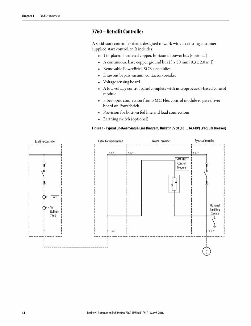
7760 – Retrofit Controller
A solid-state controller that is designed to work with an existing customer-supplied start controller. It includes:
• Tin-plated, insulated copper, horizontal power bus (optional)• A continuous, bare copper ground bus (8 x 50 mm [0.3 x 2.0 in.])• Removable PowerBrick SCR assemblies• Drawout bypass vacuum contactor/breaker• Voltage sensing board• A low voltage control panel complete with microprocessor-based control
module• Fiber-optic connection from SMC Flex control module to gate driver
board on PowerBrick• Provision for bottom fed line and load connections• Earthing switch (optional)
Figure 1 - Typical OneGear Single-Line Diagram, Bulletin 7760 (10…14.4 kV) (Vacuum Breaker)
R, S, T R, S, T R, S, T
U, V, WR, S, T
M3~
Existing Controller Cable Connection Unit Power Converter Bypass Controller
Optional Earthing Switch
SMC Flex Control Module
ToBulletin 7760
14 Rockwell Automation Publication 7760-UM001F-EN-P - March 2016
Product Overview Chapter 1
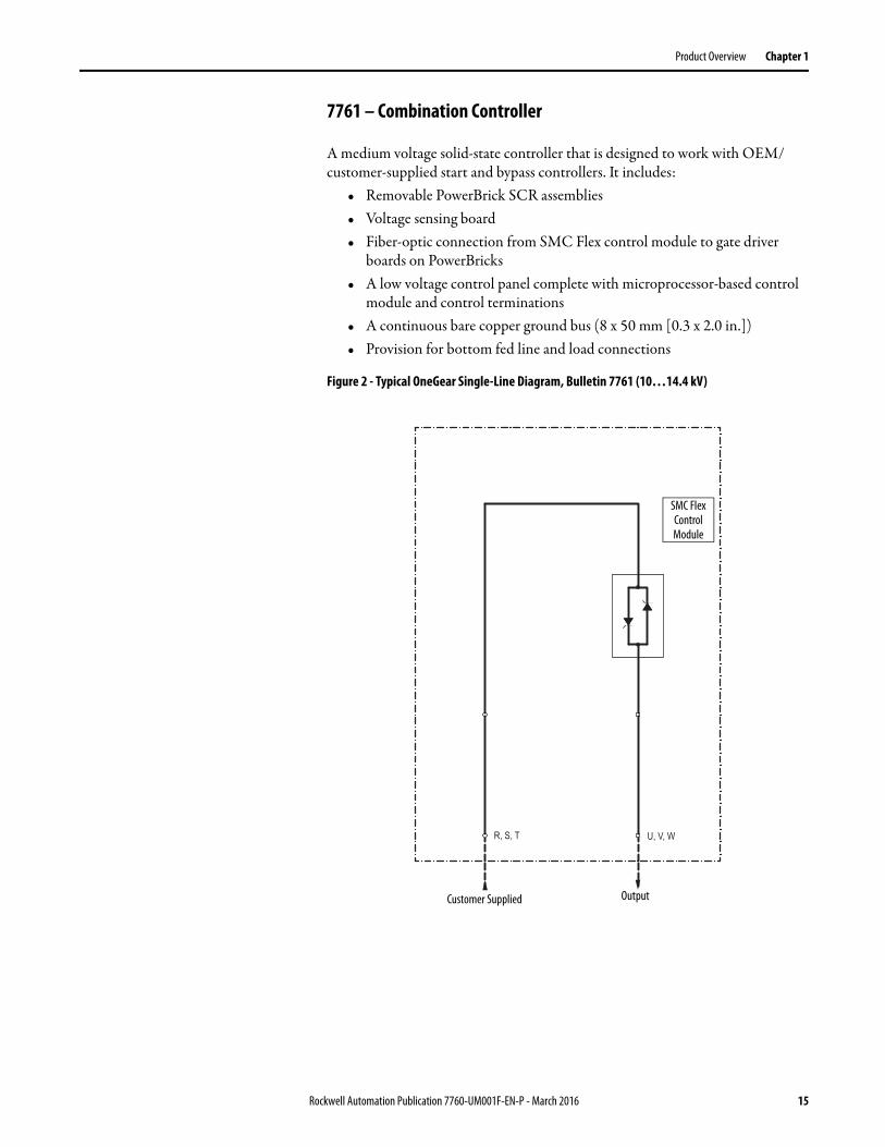
7761 – Combination Controller
A medium voltage solid-state controller that is designed to work with OEM/customer-supplied start and bypass controllers. It includes:
• Removable PowerBrick SCR assemblies• Voltage sensing board• Fiber-optic connection from SMC Flex control module to gate driver
boards on PowerBricks• A low voltage control panel complete with microprocessor-based control
module and control terminations• A continuous bare copper ground bus (8 x 50 mm [0.3 x 2.0 in.])• Provision for bottom fed line and load connections
Figure 2 - Typical OneGear Single-Line Diagram, Bulletin 7761 (10…14.4 kV)
R, S, T U, V, W
SMC Flex Control Module
OutputCustomer Supplied
Rockwell Automation Publication 7760-UM001F-EN-P - March 2016 15

Chapter 1 Product Overview
7762 – Combination Controller (Vacuum Contactor)
A medium voltage solid-state controller that provides isolation and protection for new installations. It includes:
• Tin-plated, insulated copper, horizontal power bus• A continuous, bare copper ground bus (8 x 50 mm [0.3 x 2.0 in.])• Removable PowerBrick SCR assemblies• Drawout main isolation (START) vacuum contactor• Drawout bypass (RUN) vacuum contactor• Six current-limiting power fuses • Six current transformers• Fiber-optic connection from SMC Flex control module to gate driver
board on PowerBricks• A low voltage control panel complete with microprocessor-based control
module• Space for necessary auxiliary control and metering devices• Motor overload protection (included in SMC Flex control module)• Earthing switch (optional)
Figure 3 - Typical OneGear Single-Line Diagram, Bulletin 7762 (10…12 kV)
U, V, W
R, S, T R, S, T R, S, T
Start Controller Power Converter Bypass Controller
Optional Earthing Switch
SMC Flex Control Module
ToConverterSection
ToSMC FlexControlModule
To OptionalMPS
OptionalIED
16 Rockwell Automation Publication 7760-UM001F-EN-P - March 2016
Product Overview Chapter 1
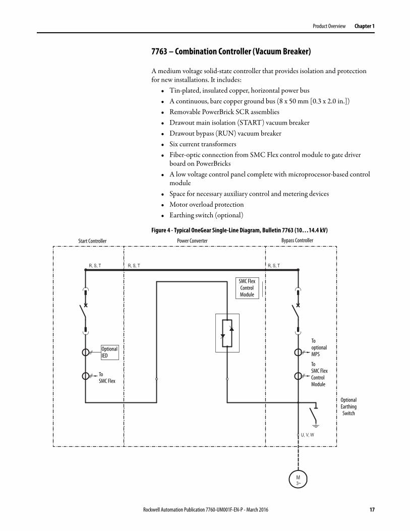
7763 – Combination Controller (Vacuum Breaker)
A medium voltage solid-state controller that provides isolation and protection for new installations. It includes:
• Tin-plated, insulated copper, horizontal power bus• A continuous, bare copper ground bus (8 x 50 mm [0.3 x 2.0 in.])• Removable PowerBrick SCR assemblies• Drawout main isolation (START) vacuum breaker• Drawout bypass (RUN) vacuum breaker• Six current transformers• Fiber-optic connection from SMC Flex control module to gate driver
board on PowerBricks• A low voltage control panel complete with microprocessor-based control
module• Space for necessary auxiliary control and metering devices• Motor overload protection • Earthing switch (optional)
Figure 4 - Typical OneGear Single-Line Diagram, Bulletin 7763 (10…14.4 kV)
U, V, W
M3~
R, S, T R, S, T R, S, T
Start Controller Power Converter Bypass Controller
Optional Earthing Switch
SMC Flex Control Module
ToSMC Flex
To optionalMPS
OptionalIED
ToSMC FlexControlModule
Rockwell Automation Publication 7760-UM001F-EN-P - March 2016 17

Chapter 1 Product Overview
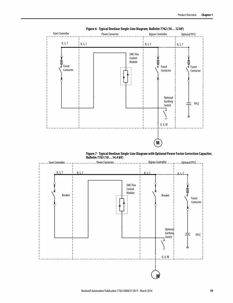
Power Factor Correction Capacitors
OneGear SMCs can be installed on a system with power factor correction capacitors. These capacitors must be installed on the line side of the Power Converter to prevent damage to the SMC Flex Controller silicon-controlled rectifiers (SCR). A separate switching contactor or breaker is required for the power factor correction capacitors. This switching device closes only after the bypass contactor has closed. The power factor correction capacitors must also be opened before the bypass contactor is opened to perform a stop function.
Acceptable optional PFCC connection methods for Bulletin 7760, 7762, and 7763 are shown in Figure 5, Figure 6, and Figure 7. The same concept applies to Bulletin 7761.
Figure 5 - Typical OneGear Single-Line Diagram Bulletin 7760 (10…14.4 kV) with two optional Power Factor Correction Capacitor positions (Vacuum Breaker)
TIP Consult that the factory is there are capacitors on the same branch circuit as the OneGear SMC.
WARNING: Do not connect power factor correction capacitors in the circuit when OneGear SMC SCRs are gating.
Power Converter Bypass Controller Optional PFCC
Breaker Fused Contactor
PFCC
SMC Flex Control Module
R, S, TR, S, T R, S, T R, S, T
U, V, W
M
R, S, T
R, S, T
Fused Contactor
PFCC
Optional PFCC Cable Connection PointExisting Controller
Breaker
Optional Earthing Switch
18 Rockwell Automation Publication 7760-UM001F-EN-P - March 2016
Product Overview Chapter 1
Figure 6 - Typical OneGear Single-Line Diagram, Bulletin 7762 (10…12 kV)
Figure 7 - Typical OneGear Single-Line Diagram with Optional Power Factor Correction Capacitor, Bulletin 7763 (10…14.4 kV)
Start Controller Power Converter Bypass Controller Optional PFCC
R, S, TR, S, T R, S, T R, S, T
SMC Flex Control Module
Optional Earthing Switch
M
PFCC
Fused Contactor
Fused Contactor
Fused Contactor
U, V, W
Start Controller Power Converter Bypass Controller Optional PFCC
Breaker BreakerFused Contactor
PFCC
SMC Flex Control Module
Optional Earthing Switch
R, S, TR, S, T R, S, T R, S, T
U, V, W
M
Rockwell Automation Publication 7760-UM001F-EN-P - March 2016 19

Chapter 1 Product Overview
Proposal for Implementation of Power Factor Correction Capacitors
1. Normal start rung, KG1 initiates start through the SMC Flex module at Term 16.
2. M closes, motor accelerates, the Up to Speed contact within the SMC Flex module between terminal 19 and 20 closes, B closes.
3. B, KG3 and KG1 then close KG4 to apply PFCC.
4. If option stop, KG1 opens KG4 immediately to drop out PFCC, and command SMC to stop.
5. CC holds in B until CC drops out, then permits B to open, option stop continues.
6. If a coast stop is initiated, the Flex opens the contact between 20 to 34; KG3 opens M and command KG4 to open CC. CC holds B until CC drops out.
Permissives Option Stop
Coast Stop
Control Relay
Bypass Control (B)
Start Control (M)
Capacitor Control (CC)
MPR
KG1
B KG3 KG1
Start
KG3 KG1
KG1
KG2
KG3
KG4
SMC Flex Control Module
CC
20 Rockwell Automation Publication 7760-UM001F-EN-P - March 2016

Product Overview Chapter 1
SMC Flex Control Module
The MV SMC Flex controller offers a full range of starting and stopping modes as standard:
• Soft Start with Selectable Kickstart• Soft Stop• Current Limit Start with Selectable Kickstart • Linear Acceleration with Selectable Kickstart(1)
• Linear Deceleration(1)
• Dual Ramp Start• Preset Slow Speed(2)
• Full Voltage Start
Other features that offer further user benefit include:• Extensive protection features• Metering• Communication capability• I/O
Innovative control option provides enhanced performance:• Pump Control (Start and Stop Control modes)
These modes, features, and options are further described in this chapter.
(1) Requires motor tachometer.
(2) This option utilizes gating patterns that result in motor and line currents which produce noise and vibration in the motor and/or distribution transformer. This must be considered before applying this option.
Rockwell Automation Publication 7760-UM001F-EN-P - March 2016 21

Chapter 1 Product Overview
Starting Modes Soft Start
This mode has the most general application. The motor is given an initial torque setting, which is user-adjustable from 0…90% of locked-rotor torque. From the initial torque level, the output voltage to the motor is steplessly increased during the acceleration ramp time. The acceleration ramp time is user-adjustable from 0…30 seconds. Once the MV SMC Flex controller senses that the motor has reached the up-to-speed condition during the voltage ramp operation, the output voltage automatically switches to full voltage, and the bypass contactor is closed.
Figure 8 - Soft Start
100%
PercentVoltage
Start Run
Time (Seconds)
InitialTorque
22 Rockwell Automation Publication 7760-UM001F-EN-P - March 2016

Product Overview Chapter 1
Selectable Kickstart
Selectable kickstart provides a power boost at start-up that is user-adjustable from 0…90% of locked rotor torque. The additional power helps motors generate higher torque to overcome the resistive mechanical forces of some applications when they are started. The selectable kickstart time is user-adjustable from 0.0…2.0 seconds.
Figure 9 - Selectable Kickstart
Current Limit Start
This starting mode provides a true current limit start that is used when limiting the maximum starting current is necessary. The Current Limit level is user-adjustable from 50%…600% of the motor's full-load ampere rating, and the current limit time is user-adjustable from 0…30 seconds. Once the MV SMC Flex controller senses that the motor has reached the up-to-speed condition during the current limit starting mode, the output voltage automatically switches to full voltage and the bypass contactor is closed.
Figure 10 - Current Limit Start
Kickstart is also available with Current Limit Start, Dual Ramp Start, and Linear Acceleration.
100%
Start Run
PercentVoltage
Start RunTime (Seconds)
InitialTorque
Kickstart
Percent FullLoad Current
Start
Time (seconds)
Rockwell Automation Publication 7760-UM001F-EN-P - March 2016 23

Chapter 1 Product Overview
Dual Ramp Start
This starting mode is useful for applications that have varying loads (and therefore varying starting torque requirements). Dual Ramp Start allows you to select between two separate Soft Start profiles with separately adjustable ramp times and initial torque settings.
Dual Ramp Start is available only with the standard controller.
Full Voltage Start
This starting mode is used for applications which require across-the-line starting. The output voltage to the motor will reach full voltage within 1/4 second.
Table 3 - Full Voltage Start
Table 2 - Dual Ramp Start
Parameter Option
Set UpThe user must select the Set-up programming mode to obtain access to the Dual Ramp parameters.
–
Basic Set-up/Starting ModeSet up as stated in previous pages.
–
Option Input 2 (Dual Ramp) (1)
Offers you the option to choose between two Soft Start profiles defined by:1. Start Mode/Ramp Time/Initial Torque, and2. Start Mode 2/Ramp Time 2/Initial Torque 2.
When this feature is turned on, the ramp time/initial torque combination is determined by a hard contact input to terminal 15. When this input signal is low, ramp time/initial torque are selected. When input signal is high, ramp time 2/initial torque 2 are selected. Once the Option 2 input has been set to Dual Ramp, you must ESC back to the Parameter (File) menu. Reenter into the Set Up menu to show both Basic Set Up and Dual Ramp.
(1) The Dual Ramp feature is available on the standard Controller.
–
Basic Set Up/Start Mode(2)
Selects the start mode for option #1.
(2) Kickstart can be programmed for both start modes.
–
Basic Set-up/Ramp TimePrograms the time period during which the controller ramps the output voltage up to full voltage for the first Start set-up.
0…30 s
Basic Set-up/Initial TorqueEstablishes and adjusts the initial reduced output voltage level for the first Soft Start set-up.
0…90% locked rotor torque
Dual Ramp/Start Mode 2(2)
Selects the start motor for option #2.–
Dual Ramp/Ramp Time 2Programs the time period during which the controller ramps the output voltage up to full voltage for the second Start set-up.
0…30 s(3)
(3) For ramp times greater than 30 s, set “Ramp Time 2” to zero and program “Start Time 2E”(parameter 130) for the new time. Do not exceed the thermal capacity of the controller.
Dual Ramp/Initial Torque 2The initial reduced output voltage level for the second Start set-up is established and adjusted with this parameter.
0…90% locked rotor torque
24 Rockwell Automation Publication 7760-UM001F-EN-P - March 2016

Product Overview Chapter 1
Preset Slow Speed
This option can be used in applications that require a slow-speed jog for general-purpose positioning. Preset Slow Speed provides either 7% of base speed (low) or 15% of base speed (high) settings in the forward direction. Reverse can also be programmed and offers 10% of base speed (low) and 20% of base speed (high) settings.
Figure 11 - Preset Slow Speed Option
Parameter Option
Starting ModeMust be programmed for Full Voltage.
Full Voltage
100%
Start
Forward15% – High
7% – Low
Time (seconds)
Reverse
10% – Low
20% – High
MotorSpeed
Run
IMPORTANT Slow speed running is not intended for continuous operation due to reduced motor cooling. The two starts per hour limitation also applies to slow speed operation. This option employs a cycle-skipping scheme, which produces limited torque. Applications must be checked with the factory.
Rockwell Automation Publication 7760-UM001F-EN-P - March 2016 25
Chapter 1 Product Overview
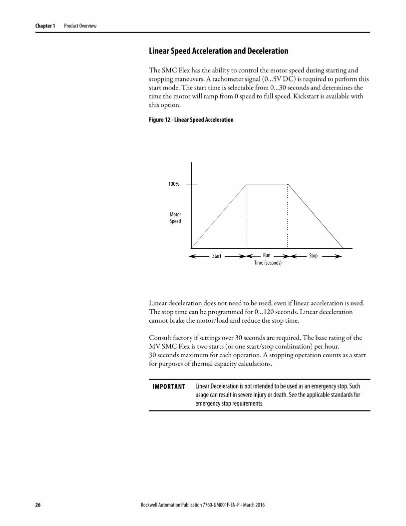
Linear Speed Acceleration and Deceleration
The SMC Flex has the ability to control the motor speed during starting and stopping maneuvers. A tachometer signal (0…5V DC) is required to perform this start mode. The start time is selectable from 0…30 seconds and determines the time the motor will ramp from 0 speed to full speed. Kickstart is available with this option.
Figure 12 - Linear Speed Acceleration
Linear deceleration does not need to be used, even if linear acceleration is used. The stop time can be programmed for 0…120 seconds. Linear deceleration cannot brake the motor/load and reduce the stop time.
Consult factory if settings over 30 seconds are required. The base rating of the MV SMC Flex is two starts (or one start/stop combination) per hour, 30 seconds maximum for each operation. A stopping operation counts as a start for purposes of thermal capacity calculations.
100%
Start Run Stop
100%
StartTime (seconds)
MotorSpeed
Run Stop
IMPORTANT Linear Deceleration is not intended to be used as an emergency stop. Such usage can result in severe injury or death. See the applicable standards for emergency stop requirements.
26 Rockwell Automation Publication 7760-UM001F-EN-P - March 2016

Product Overview Chapter 1
Soft Stop
This feature can be used in applications that require an extended coast-to-rest time. The voltage ramp-down time is user-adjustable from 0…120 seconds and is adjusted independently from the starting time. The load stops when the output voltage drops to a point where the load torque is greater than the developed motor torque.
Figure 13 - Soft Stop Option
Consult factory if settings over 30 seconds are required. The base rating of the MV SMC Flex is two starts (or one start/stop combination) per hour, 30 seconds maximum for each operation. A stopping operation counts as a start for purposes of thermal capacity calculations.
100%
Start Run Soft Stop
PercentVoltage
Start RunTime (Seconds)
InitialTorque
Soft Stop
Soft Stop
Coast-to-RestKickstart
IMPORTANT Soft Stop is not intended to be used as an emergency stop. Such usage can result in severe injury or death. See the applicable standards for emergency stop requirements.
Rockwell Automation Publication 7760-UM001F-EN-P - March 2016 27

Chapter 1 Product Overview
Protection and Diagnostics The MV SMC Flex controller provides the following protective and diagnostic features:
Overload
The MV SMC Flex controller meets applicable requirements as a motor overload protection device. Thermal memory provides added protection and is maintained even when control power is removed. The built-in overload algorithm controls the value that is stored in Parameter 12, Motor Thermal Usage (see Chapter 3, Programming). An Overload Fault occurs when this value reaches 100%. The parameters in Table 4 provide application flexibility and easy setup.
Table 4 - Overload Parameters
Notes:
1. If the MV SMC Flex is used to control a multi-speed motor, or multiple motors, the Overload Class parameter must be programmed to “OFF” and separate overload relays must be supplied for each speed/motor.
2. Automatic reset of an overload fault requires the start input to be cycled in a 2-wire control scheme.
3. The trip rating is 117% of the programmed FLC.
Figure 14 and Figure 15 provide the overload trip curves for the available trip classes.
Separate protection relay c/w instantaneous overcurrent protection is required when used with vacuum breakers.
Parameter Range
Overload Class Disable, 10, 15, 20, 30
Overload Reset Manual...Auto
Motor FLC 1.0…2200 A
Service Factor 0.01…1.99
IMPORTANT During slow speed operations, current waveforms exhibit non-sinusoidal characteristics. These non-sinusoidal characteristics inhibit the controller's current-measurement capability. To compensate for additional motor heating that may result, the controller uses motor thermal modeling, which increments motor thermal usage. This compensation takes place when the Preset Slow Speed option is used.
28 Rockwell Automation Publication 7760-UM001F-EN-P - March 2016

Product Overview Chapter 1
Figure 14 - Overload Trip Curves
Figure 15 - Restart Trip Curves after Auto Reset
1.0
10.0
100.0
1000.0
10000.0
1 10 2 3 9 8 7 6 5 4 0.1
1.0
10.0
100.0
1000.0
1 10 2 3 9 8 7 6 5 4 1.0
10.0
100.0
1000.0
10000.0
1 10 2 3 9 8 7 6 5 4 1.0
10.0
100.0
1000.0
10000.0
1 10 2 3 9 8 7 6 5 4 1 10 2 3 9 8 7 6 5 4 1 10 2 3 9 8 7 6 5 4 1 10 2 3 9 8 7 6 5 4 1 10 2 3 9 8 7 6 5 4
Multiples of FLC Multiples of FLC Multiples of FLCMultiples of FLC
Appr
oxim
ate T
rip Ti
me (
seco
nds)
Appr
oxim
ate T
rip Ti
me (
seco
nds)
Appr
oxim
ate T
rip Ti
me (
seco
nds)
Appr
oxim
ate T
rip Ti
me (
seco
nds)
Approximate trip time for 3-phasebalanced condition from cold start
Approximate trip time for 3-phasebalanced condition from cold start
Class 10 Class 15 Class 20 Class 30
100000
1000
100
10
1
0100% 1000%
Class 10Class 15Class 20Class 30
Seco
nds
Class 10Class 15Class 20Class 30
Class 10Class 15Class 20Class 30
Auto Reset TimesClass 10 = 90 sClass 15 = 135 sClass 20 = 180 sClass 30= 270 s
Percent Full Load Current Setting
Rockwell Automation Publication 7760-UM001F-EN-P - March 2016 29

Chapter 1 Product Overview
Underload
Using the underload protection of the MV SMC Flex controller, motor operation can be halted if a sudden drop in current is sensed.
The MV SMC Flex controller provides an adjustable underload trip setting from 0…99% of the programmed motor full load current rating. Trip delay time can be adjusted from 0…99 seconds.
Underload protection is disabled during slow speed and braking operations.
Undervoltage
Using the undervoltage protection of the MV SMC Flex, motor operation can be halted if a sudden drop in voltage is detected.
The MV SMC Flex controller provides an adjustable undervoltage trip setting from 0…99% of the programmed motor voltage. Trip delay time can be adjusted from 0…99 seconds.
For medium voltage applications, undervoltage protection must be set at or above 80%.
An alarm (pre-fault) indication level can be programmed to indicate that the unit is getting close to faulting. The alarm modification information is displayed through the LCD, HIM, Communication (if applicable), and alarm contact closing.
Overvoltage
Using the overvoltage protection of the MV SMC Flex, motor operation can be halted if a sudden increase in voltage is detected.
The MV SMC Flex controller provides an adjustable overvoltage trip setting from 0…199% of the programmed motor voltage. Trip delay time can be adjusted from 0…99 seconds.
For medium voltage applications, overvoltage protection must be set at or below 110%.
An alarm (pre-fault) indication level can be programmed to indicate that the unit is getting close to faulting. The alarm modification information is displayed through the LCD, HIM, Communication (if applicable), and alarm contact closing.
Undervoltage, overvoltage, and voltage unbalance protection are disabled during braking operation.
30 Rockwell Automation Publication 7760-UM001F-EN-P - March 2016

Product Overview Chapter 1
Unbalance
The MV SMC Flex is able to detect an unbalance in line voltages. Motor operation can be halted if the unbalance is greater than the desired range.
The MV SMC Flex controller provides an adjustable unbalance setting from 0…25% of the line voltages. Trip delay time can be adjusted from 0…99 seconds.
An alarm (pre-fault) indication level can be programmed to indicate that the unit is getting close to faulting. The alarm modification information is displayed through the LCD, HIM, Communication (if applicable), and alarm contact closing.
Undervoltage, overvoltage, and voltage unbalance protection are disabled during braking operation.
Stall Protection and Jam Detection
The MV SMC Flex controller provides both stall protection and jam detection for enhanced motor and system protection.
• Stall protection is user-adjustable from 0.0…10.0 seconds (enabled only after the programmed start time expires). It is recommended that it is set at 1.0 second.
• An alarm (pre-fault) indication level can be programmed to indicate that the unit is getting close to faulting. The alarm modification information is displayed through the LCD, HIM, Communication (if applicable), and alarm contact closing.
• Jam detection allows you to determine the jam level (up to 1000% of the full-load current rating of the motor) and the delay time (up to 99.0 seconds) for application flexibility.
Figure 16 - Stall Protection
PercentFull Load
Current
Programmed Start Time Stall
Time (seconds)
Rockwell Automation Publication 7760-UM001F-EN-P - March 2016 31

Chapter 1 Product Overview
Figure 17 - Jam Detection
Jam Detection is disabled during slow speed and braking operation.
Ground Fault
In isolated or high impedance-grounded systems, core-balanced current sensors are typically used to detect low-level ground faults that are caused by insulation breakdowns or entry of foreign objects. Detection of such ground faults can be used to interrupt the system to prevent further damage, or to alert the appropriate personnel to perform timely maintenance.
The ground fault detection capabilities consist of a core balance current transformer for 1…5A core-balanced ground fault protection, with the option of enabling Ground Fault Trip, Ground Fault Alarm, or both (a core balance CT can be provided with 1562E units).
Ground Fault Trip
The MV SMC Flex trips with a ground fault indication if:• No trip currently exists• Ground fault protection is enabled• GF Inhibit Time has expired• GF Current is equal to or greater than the GF Trip Level for a time period
greater than the GF Trip Delay
Parameter 75, Gnd Flt Inh Time, allows the installer to inhibit a ground fault trip from occurring during the motor starting sequence and is adjustable from 0…250 seconds.
Parameter 74, Gnd Flt Delay, allows the installer to define the time period a ground fault condition must be present before a trip occurs. It is adjustable from 0.1…25 seconds.
Parameter 73, Gnd Flt Level, allows the installer to define the ground fault current at which the MV SMC Flex trips. It is adjustable from 1.0…5.0 A.
100%
Running JamTime (seconds)
PercentFull Load
Current
Running Jam
Time (seconds)
32 Rockwell Automation Publication 7760-UM001F-EN-P - March 2016

Product Overview Chapter 1
Ground Fault Alarm
The MV SMC Flex will indicate a Ground Fault Alarm if:• No warning currently exists• Ground fault alarm is enabled• GF Inhibit Time has expired• GF Current is equal to or greater than the Gnd Flt A Lvl
Parameter 77, Gnd Flt A Lvl, allows the installer to define the ground fault current at which an alarm is indicated. It is adjustable from 1.0…5.0 A.
Parameter 78, Gnd Flt A Dly, allows the installer to define the time period a ground fault alarm condition must be present before a trip occurs. It is adjustable from 0.1…25 seconds.
Thermistor/PTC Protection
The MV SMC Flex provides terminals 23 and 24 for the connection of positive temperature coefficient (PTC) thermistor sensors. PTC sensors are commonly embedded in motor stator windings to monitor the motor winding temperature. When the motor winding temperature reaches the PTC sensor’s temperature rating, the PTC sensor’s resistance transitions from a low to high value. Since PTC sensors react to actual temperature, enhanced motor protection can be provided to address such conditions as obstructed cooling and high ambient temperatures.
Table 5 defines the MV SMC Flex PTC thermistor input and response ratings.
Table 5 - PTC Input Ratings
IMPORTANT The ground fault inhibit timer starts after the maximum phase of load current transitions from 0 A to 30% of the minimum FLA Setting or the GF Current is greater than or equal to 0.5 A. The MV SMC Flex does not begin monitoring for a ground fault condition until the Gnd Flt Inh Time expires.
Response Resistance 3400 Ω ± 150 Ω
Reset Resistance 1600 Ω ± 100 Ω
Short-circuit Trip Resistance 25 Ω ± 10 Ω
Maximum Voltage at PTC Terminals (RPTC - 4 k ) < 7.5V
Maximum Voltage at PTC Terminals (RPTC = open) 30V
Maximum Number of Sensors 6
Maximum Cold Resistance of PTC Sensor Chain 1500 Ω
Response Time 800 ms
Rockwell Automation Publication 7760-UM001F-EN-P - March 2016 33

Chapter 1 Product Overview
Figure 18 illustrates the required PTC sensor characteristics, per IEC-34-11-2.
Figure 18 - PTC Sensor Characteristics per IEC-34-11-2
PTC Trip
The MV SMC Flex trips with a PTC indication if:• No other fault currently exists• PTC protection is enabled• The resistance across terminals 23 and 24 is either greater than the relay’s
response resistance or less than the short-circuit trip resistance.
Open Gate
An open-gate fault indicates that improper SCR firing, typically caused by an open SCR gate or driver system, has been detected on one of the power poles. Before the controller shuts down, it attempts to start the motor a total of three times (or as programmed in Parameter 82).
An open gate is detected when the module sends a gate signal to the SCRs but does not detect that they turned on. SCR turn-on is detected when the voltage across the leg (L-T) collapses. The Open Gate detection is active during starting or stopping only.
34 Rockwell Automation Publication 7760-UM001F-EN-P - March 2016
Product Overview Chapter 1
Line Faults
The MV SMC Flex controller continually monitors line conditions for abnormal factors. Pre-start protection includes:
• Line Fault (with phase indication)– Line voltage loss– Missing load connection– Shorted SCR
Running protection includes:• Line Fault (no phase indication)
– Line voltage loss– Missing load connection
Phase reversal protection u can be toggled either ON or OFF.
Phase reversal protection is functional only at pre-start.
Excessive Starts/Hour
The MV SMC Flex module allows you to program the desired number of starts per hour (up to 99). This helps eliminate motor stress that is caused by repeated starting over a short time period.
The base rating of the MV SMC Flex is two starts (30 seconds each max.) per hour. Applications which require more frequent starts, or longer duration starts, must be reviewed with the factory to avoid equipment damage.
Overtemperature
The power module temperature is monitored during starting and stopping maneuvers by thermistors. The thermistor is connected to the gate driver board where it is processed, and the status is transmitted by fiber-optic cable through the interface board to the control module. When an overtemperature condition exists (greater than 85°C [185°F]), the control module trips and indicates a "PTC Power Pole" fault. This trip can also indicate a problem with the gate driver board, fiber-optic cable, or interface board.
An overtemperature condition could indicate high ambient temperature, overloading, or excessive cycling. After the power module temperature is reduced to allowable levels, the fault can be cleared (see Maintenance on page 115 for instructions).
Rockwell Automation Publication 7760-UM001F-EN-P - March 2016 35

Chapter 1 Product Overview
Metering Power monitoring parameters include:• Three-phase current• Three-phase voltage• Power in MW • Power usage in MWh • Power factor • Motor thermal capacity usage• Elapsed time• Motor speed (full speed %, with use of optional tachometer input)
Notes:
1. Voltage measurement is not available during the braking operation of the SMB Smart Motor Braking, Accu-Stop, and Slow Speed with Braking control options.
2. The elapsed time and MWh values are automatically saved to memory every 12 hours.
3. Motor thermal capacity usage is determined by the built-in electronic thermal overload. An overload fault occurs when this value reaches 100%.
I/O The SMC Flex accepts up to two inputs and four outputs controlled over a network. The two inputs are controlled at terminal 16 (Option Input 1), and terminal 15 (Option Input 2). For these two inputs, see Chapter 3 for the parameter settings and see Chapter 7 for the bit identification. By using these two terminals as inputs, the Stop Input needs to be programmed to meet the desired stop functionality.
The four outputs are Aux 1, Aux 2, Aux 3, and Aux #4. All auxiliary contacts are programmable to the function found on page 71. If programmed to Network or Network NC, they can be controlled over a Network. See Table 34 which defines the Logic Command Word (Control).
For MV applications, some of the I/O are assigned to specific functions. See on page 38 for additional details.
36 Rockwell Automation Publication 7760-UM001F-EN-P - March 2016

Product Overview Chapter 1
Communication A serial interface port (DPI) is provided as standard, which allows connection to the Bulletin 20-HIM LCD human interface modules.
Figure 19 - DPI Location
Programming Setup is easy with the built-in keypad and three-line, sixteen-character backlit LCD. Parameters are organized in a three-level menu structure, using a text format for straightforward programming.
Figure 20 - Built-in Keypad and LCD
ATTENTION: Two peripheral devices can be connected to the DPI. The maximum output current through the DPI is 280 mA.
Port 5 – DPI Communications
Port 2
Ports 2 and 3 when two HIMsare connected with a splitter
Rockwell Automation Publication 7760-UM001F-EN-P - March 2016 37
Chapter 1 Product Overview
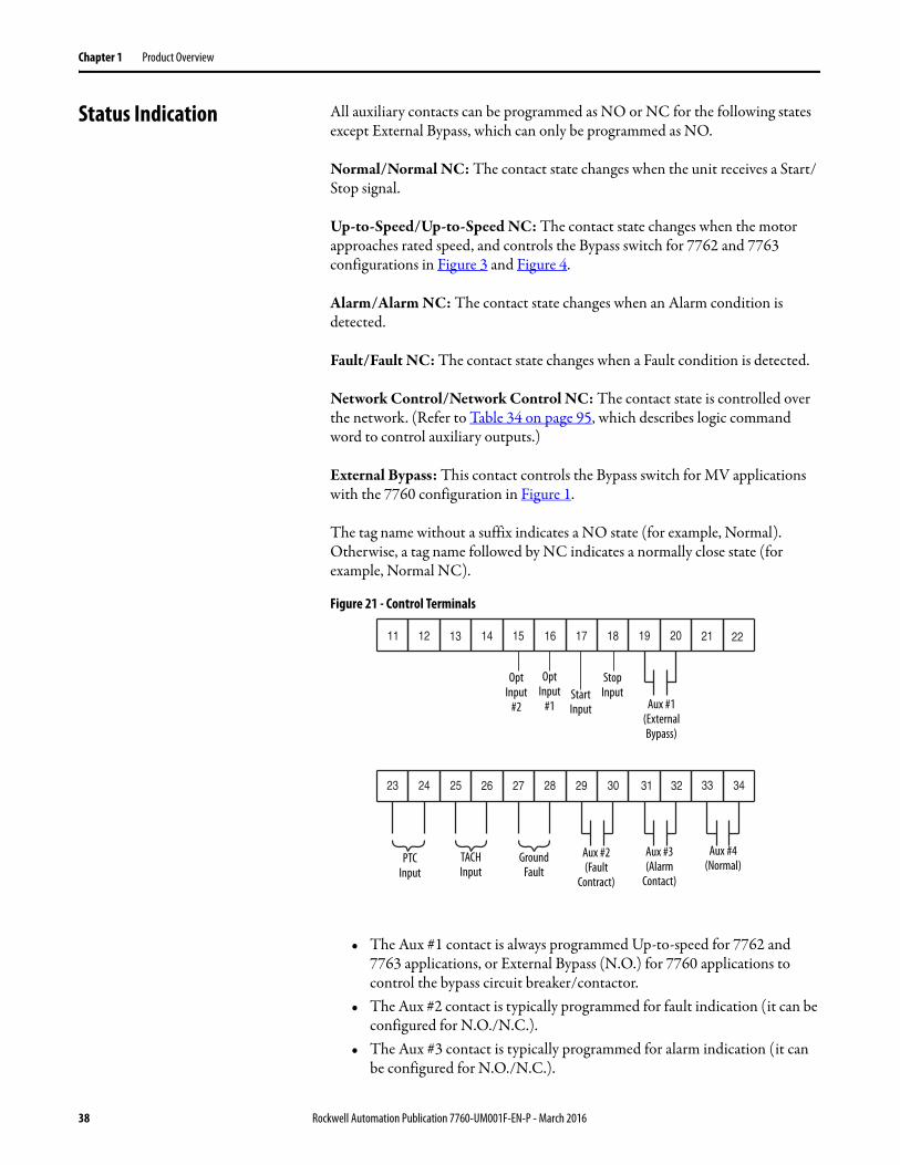
Status Indication All auxiliary contacts can be programmed as NO or NC for the following states except External Bypass, which can only be programmed as NO.
Normal/Normal NC: The contact state changes when the unit receives a Start/Stop signal.
Up-to-Speed/Up-to-Speed NC: The contact state changes when the motor approaches rated speed, and controls the Bypass switch for 7762 and 7763 configurations in Figure 3 and Figure 4.
Alarm/Alarm NC: The contact state changes when an Alarm condition is detected.
Fault/Fault NC: The contact state changes when a Fault condition is detected.
Network Control/Network Control NC: The contact state is controlled over the network. (Refer to Table 34 on page 95, which describes logic command word to control auxiliary outputs.)
External Bypass: This contact controls the Bypass switch for MV applications with the 7760 configuration in Figure 1.
The tag name without a suffix indicates a NO state (for example, Normal). Otherwise, a tag name followed by NC indicates a normally close state (for example, Normal NC).
Figure 21 - Control Terminals
• The Aux #1 contact is always programmed Up-to-speed for 7762 and 7763 applications, or External Bypass (N.O.) for 7760 applications to control the bypass circuit breaker/contactor.
• The Aux #2 contact is typically programmed for fault indication (it can be configured for N.O./N.C.).
• The Aux #3 contact is typically programmed for alarm indication (it can be configured for N.O./N.C.).
11 12 13 14 15 16 17 18 19 20 21
23 24 25 26 27 28 29 30 31 32 33 34
22
Opt Input
#2
Opt Input
#1Start Input
Stop Input
Aux #1(External Bypass)
PTC Input
TACH Input
Ground Fault
Aux #2 (Fault
Contract)
Aux #3 (Alarm
Contact)
Aux #4 (Normal)
38 Rockwell Automation Publication 7760-UM001F-EN-P - March 2016

Product Overview Chapter 1
• The Aux #4 contact is always configured as Normal (N.O.) to control the line circuit breaker/contactor.
Network inputs can be obtained through proper programming of Option Input #1 and Option Input #2 (see Appendix B for available options).
Control Options
Pump Control Option
This option reduces surges during the starting and stopping of a centrifugal pump by smoothly accelerating and decelerating the motor. The microprocessor analyzes the motor variables and generates commands that control the motor and reduce the possibility of surges occurring in the system.
The motor current varies during the acceleration period, and can be near the motor rated starting current. The pump algorithm does not limit starting current since full voltage is needed to reach full speed with a loaded motor.
The starting time is programmable from 0...30 seconds, and the stopping time is programmable from 0...120 seconds.
Kickstart is available with this option.
Pump Application Considerations
1. Consult factory if start time settings over 30 seconds are required. The base rating of the MV SMC Flex is two starts (or one start/stop combination) per hour, 30 seconds maximum for each operation. A stopping operation counts as a start for purposes of thermal capacity calculations.
2. The Pump Control option functions only for centrifugal pumps. It is not suited for positive displacement, piston, or other types of pumps.
3. The Pump Stop option functions only for a centrifugal pump running at greater than approximately 2/3 of the motor rated horsepower.
4. Pump applications with input and/or output valves that are closed during starting and/or stopping may not benefit from the Pump Control option. Consult the factory for applications with valves.
IMPORTANT The options listed in this section are mutually exclusive and must be specified when ordering. An existing controller may be upgraded to another control option by replacing the control module and possibly other components. Consult your nearest Rockwell Automation sales office.
Rockwell Automation Publication 7760-UM001F-EN-P - March 2016 39

Chapter 1 Product Overview
5. For starting or stopping times longer than 15 seconds, review the power fuse selection so no element damage occurs. Consult the fuse minimum melting time-current characteristic curve so, at 1.1 times the full voltage locked rotor current of the motor, the actual starting or stopping time does not exceed 75% of the fuse melting time.
6. Motor overload and/or upstream breaker settings may have to be adjusted to allow the starting or stopping current to flow for extended periods.
Figure 22 - Pump Control Option
Braking Control Options
The Braking Control options (Smart Motor Braking, Accu-Stop and Slow Speed with Braking) require attention to specific application considerations, and therefore are not offered for standard use in MV applications. Consult factory for further assistance.
Hardware Description The following sections contain descriptions of system components and system operation. Each section will be described to give the user an understanding of the MV SMC Flex to facilitate operation and maintenance of the system. See Figure 23 and Figure 24, Typical MV SMC Flex Power System.
ATTENTION: Pump stopping is not intended to be used as an emergency stop. See the applicable standard for emergency stop requirements.
ATTENTION: Pump stopping may cause motor heating depending on the mechanical dynamics of the pumping system. Therefore, select the lowest stopping time setting that will satisfactorily stop the pump.
Pump Start Run Pump Stop
100%
MotorSpeed
Pump Start Run Pump StopTime (seconds)
40 Rockwell Automation Publication 7760-UM001F-EN-P - March 2016

Product Overview Chapter 1
Power Module
The three-phase AC line controller consists of three removable power modules, one for each phase. Each power module includes series connected PowerBricks (5 for 12 kV, and 6 for 13.8 kV applications), an isolated current loop power system, a set of fiber-optic cables for SCR control, and line and load connections. Each PowerBrick includes two inverse parallel connected SCRs plus snubbers and self-powered gate driver circuits.
Each PowerBrick includes a snubber circuit to limit the rate of rise in voltage across each SCR pair. The module also includes patented current loop gate driver circuits that derive their power primarily from the snubber circuit.
Voltage sharing resistors are connected across each SCR pair to provide static voltage balance for series-connected SCRs. These resistors are tapped to provide a reference for overvoltage protection circuitry on the gate driver board.
A voltage sensing board is used to reduce the line-side and load-side voltages to lower levels that can be measured by the SMC Flex control module.
Current Loop Gate Driver (CLGD) Board
This board provides the turn-on capability for SCR devices. The board also provides optical fiber isolation between itself and the gating source logic. It is primarily powered by recovering energy from the snubber circuit, so it is fully isolated from the control and logic circuits. The board also receives short-term power from the current loop power supply.
The MV SMC Flex has three heatsinks that are fitted with a thermistor to monitor temperature rise. The circuitry on the gate driver board accepts the thermistor, and drives a fiber-optic cable if the temperature is below the setpoint (85 °C, 185 °F). If the temperature rises above the setpoint, the driver is turned off, and the MV SMC Flex is signaled to stop gating and initiate a temperature fault. For a detailed layout of this circuit board, see Figure 28 in Chapter 2.
Interface Board
This circuit board takes current transformer signals plus line-side and load-side voltage feedback signals from the voltage sensing board and passes them to the SMC Flex for processing. The control module produces gating signals for the SCRs, which are received on the interface board, and used to drive fiber-optic transmitters. The gating signals are sent to the gate-driver circuit board via fiber-optic cables. The interface board also receives temperature feedback from the gate-driver board via fiber-optic cables. If the heatsink temperature rises above a set value, a signal is sent to the SMC Flex to stop gating the SCRs and initiate a temperature fault. For a detailed layout of this circuit board, see Figure 27 in Chapter 2.
Rockwell Automation Publication 7760-UM001F-EN-P - March 2016 41

42Rockwell Autom
ation Publication 7760-UM001F-EN-P - M
arch 2016
Chapter 1Product Overview
Figure 23 - Typical OneGear SMC Flex Power System – Bulletin 7763
-QE
MTR
-BC2
-BC1
-BC3
T3
T2
T1
L1
L2
GRD
L3
24C
PHASE A PHASE B PHASE C
FO3FO2FO1
FO4-15 FO16-27 FO28-39
GND2GND1
J1
1
2
3
4
5
6
POWER
IN
GNL1
TB1
GATE TRANSMITTERS
TB6
ØA
U16U18U20
TEMP.GATE TRANSMITTERS
ØBTX7
GDPS
TX1
VSB
TB21
GL2/NL1 POW
ERIN
TB1
ØCTX13
-RS 1 -RS n
CT INPUTS
C+
A-A+
B+B-
TB5
C-
J3
-QB
-QB
2
1
OV1
C1S1
OV2
RR1/2
RS1/2/3
C2S2CS
RX1 GTX1 C T
-GP1TEST
-BC
-+ OV S C
RX1 TX1 TCG
OV
-BC
TEST+ -
-GP2
S C
G1 G2
T T
G2
2
1
C1S1RS1/2/3
C2S2 CS
G1
TT
RX1 GTX1 C T
-GP2TEST
-BC
-+ OV S C
RX1 TX1 TCG
OV
-BC
TEST+ -
-GP1
S C
OV2 OV1
RR1/2
RX
-KF1
-KF2
-GP
-KF2
-BC
-KF1
-QB-QE-RS
-BV
10-12kV 512.1-14.4kV 6
L3
L2
L1
1
-BC2
-BC1
-BC3
-BV
POWER
OUT
WIRE CONNECTIONS FOR PHASE AWIRE CONNECTIONS FOR PHASE BCONNECTIONS SHOWN FOR PHASE CCURRENT LOOP CONDUCTORS PASS THROUGH THE C.T.'S ON THE CURRENT LOOP ASSEMBLYREMOTE EQUIPMENT
- CURRENT TRANSFORMER- VOLTAGE SENSING BOARD- CURRENT LOOP GATE DRIVER BOARD- SMC FLEX FIBRE OPTIC BOARD- SMC FLEX INTERFACE BOARD- CIRCUIT BREAKER- EARTHING SWITCH (OPTIONAL EQUIPMENT)- SMC FLEX POWERBRICK ASSEMBLY
CUSTOMER’SINCOMING LINE
LEGEND
INCOMING LINEUNIT
TO SMC FLEX CT INPUTS
FROMCONTROL
CIRCUIT
NUMBER OF POWERBRICKS (n)
VOLTAGE
POWER CONVERTER
START CONTROLLER
BYPASS CONTROLLER
FROM CONTROL CIRCUIT
FROM CURRENT LOOP CT
TO SMC FLEX CONTROL MODULE
FROM START CONTROLLER PHASE CTs

Rockwell Automation Publication 7760-UM
001F-EN-P - March 2016
43
Product OverviewChapter 1
Figure 24 - Typical OneGear SMC Flex Power System – Bulletin 7760
-QE
MTR
T3
T2
T1
HASE CK FROM LLER
L1
L2
GRD
L3
24C
PHASE A PHASE B PHASE C
FO3FO2FO1
FO4-15 FO16-27 FO28-39
GND2GND1
J1123456
POW
ERIN
GNL1
TB1
GATE TRANSMITTERS
TB6
ØA
U16
U18
U20
TEMP.
GATE TRANSMITTERS
ØBTX7
GDPS
TX1VSB
TB21
G
L2/N
L1 POWER
IN
TB1
ØCTX13
-RS 1 -RS n
CT INPUTS
C+
A-
A+
B+
B-
TB5
C-
J3
-QB
2
1
OV1
C1S1
OV2
RR1/2
RS1/2/3
C2S2CS
RX1 GTX1 C T
-GP1TEST
-BC
-+ OV S C
RX1 TX1 TCG
OV
-BC
TEST+ -
-GP2
S C
G1 G2
T T
G2
2
1
C1S1RS1/2/3
C2S2 CS
G1
TT
RX1 GTX1 C T
-GP2TEST
-BC
-+ OV S C
RX1 TX1 TCG
OV
-BC
TEST+ -
-GP1
S C
OV2 OV1
RR1/2
RX
-KF1
-KF2
-GP
-KF2
-BC
-KF1
-QB-QE-RS
-BV
10-12kV 512.1-14.4kV 6
-QB2
L3
L2
L1
2
-BC2
-BC1
-BC3
1
-BV
POWER
OUT
WIRE CONNECTIONS FOR PHASE AWIRE CONNECTIONS FOR PHASE BCONNECTIONS SHOWN FOR PHASE CCURRENT LOOP CONDUCTORS PASS THROUGH THE C.T.'S ON THE CURRENT LOOP ASSEMBLYREMOTE EQUIPMENT
- CURRENT TRANSFORMER- VOLTAGE SENSING BOARD- CURRENT LOOP GATE DRIVER BOARD- SMC FLEX FIBRE OPTIC BOARD- SMC FLEX INTERFACE BOARD- CIRCUIT BREAKER- EARTHING SWITCH (OPTIONAL EQUIPMENT)- SMC FLEX POWERBRICK ASSEMBLY
LEGEND
EXISTING CONTROLLER
TO SMC FLEX CT INPUTS
FROMCONTROL
CIRCUIT
NUMBER OF POWERBRICKS (n)
VOLTAGE
POWER CONVERTER
CABLE CONNECTION UNIT
BYPASS CONTROLLER
FROM CONTROL CIRCUIT
FROM CURRENT LOOP CT
TO SMC FLEX CONTROL MODULE
0…5 A MOTOR PCURRENT FEEDBAEXISTING CONTRO
SHORT CIRCUIT PROTECTIVE DEVICE: MAY BE A CIRCUIT BREAKER OR FUSED CONTACTOR WITH DISCONNECT

Chapter 1 Product Overview
Functional Description Bulletin 7763 – Basic Control – Controlled Start only
When wired as shown in Figure 25 on page 45, the controller operates as follows:
Pressing the "Start" button initiates the start sequence. Relay "-KG1" closes and applies control power to terminal 17 of the SMC Flex module. The auxiliary contact #4 (set for "normal") closes, picking up "-KG3", which completes the hold-in circuit on the start button, and closes the Start Breaker.
The SMC Flex module examines the line voltage, looks for fault conditions, checks phase rotation, calculates zero crossing information, and begins gating the SCRs to start the motor.
When the motor approaches rated speed, the SMC Flex module closes the "AUX1" (Up-to-Speed) auxiliary contacts, closing relay "-KG2", which closes the bypass breaker. The motor then runs at full line voltage.
When the "Stop" button is pressed, the "-KG1" relay opens terminal 17 on the SMC Flex module. The "AUX4" and "AUX1" contacts open, which opens the start and bypass breakers, allowing the motor to stop.
Bulletin 7760 – Basic Control – Controlled Start Only
The Bulletin 7760 is intended for addition to an existing motor controller, which provides circuit isolation, motor switching, and overload and overcurrent protection. When wired as shown in Figure 26, the controller operates as follows:
When a start is initiated in the existing motor controller and the contactor (or breaker) closes, a contact must be supplied to tell the 7760 to start also. A "-KG1" contact applies control voltage to terminal 17 of the SMC Flex module.
When stopping the motor, the contactor in the existing controller opens, removing power from the motor, and then the "-KG1" relay. The "AUX1" contact (External Bypass) is held closed for 10 seconds to keep the bypass contactor closed for a short time.
The “Fault” contact on the SMC Flex module must be wired into the existing controller to trip the main contactor (or breaker) in the event of a fault condition sensed by the SMC Flex module.
If possible, it is better to have the SMC Flex module control the main contactor (or breaker) directly. In this case, the control circuit would look like, and function similar to, the descriptions above for the Bulletin 7763.
44 Rockwell Automation Publication 7760-UM001F-EN-P - March 2016

Product Overview Chapter 1
Figure 25 - Typical OneGear SMC Flex Control Circuit (without Stop Control) – Bulletin 7763
-BC4
ØA ØB ØC
H1 H3 H2 H4
230V
OR
-TT1
-FB
29 3028272524 2623 33 34
201918171514 161311 12
DPI
21 22
31 32
GROUNDFAULT
TACHINPUT
PTCINPUT
-FB
-FB
-TT1
H1 H3 H2 H4
X1 X2
115V
-BC4
-KG1
-KG1
-KG3
AUX.1UP-TO-SPEED
AUX.4NORMAL
AUX.2FAULT
AUX.3ALARM
-KG2
-KG1
-KG3
-KG3
POWER IN
-KG3
-KG2
-KG1
POWER IN
R
Legend
Current Loop Conductors pass through the C.T.’s on the current loop assemblyCurrent Loop Current SensorMiniature Circuit Breaker or Control Fuse
Start/Stop Signal Control Relay
Bypass Controller Pilot Control RelayStart Controller Pilot Control RelayCurrent Loop Transformer
Control Power
Start/Stop Signal Control Relay
Start Controller Pilot Control Relay
SMC Flex to be programmed by the customer before start-up
To SMC FlexInterface
Board - TB6
From SMC Flex Interface Board
SMC Flex control terminals
SMC Flex Interface Board
SMC Flex Fiber-optic Board
Bypass Controller Pilot Control Relay
STARTSTOP
Rockwell Automation Publication 7760-UM001F-EN-P - March 2016 45

Chapter 1 Product Overview
Figure 26 - Typical OneGear SMC Flex Control Circuit (without Stop Control) – Bulletin 7760
-BC4
ØA ØB ØC
H1 H3 H2 H4
230V
OR
-TT1
-FB
29 3028272524 2623 33 34
201918171514 161311 12
DPI
21 22
31 32
GROUNDFAULT
TACHINPUT
PTCINPUT
-FB
-FB
-TT1
H1 H3 H2 H4
X1 X2
115V
-BC4
-KG1
AUX.1EXTERNAL BYPASS
AUX.4NORMAL
AUX.2FAULT
AUX.3ALARM
-KG2
-KG1
POWER IN
-KG2
-KG1
POWER IN
R
Control Power
Start/Stop Signal Control Relay
Bypass Controller Pilot Control Relay
SMC Flex to be programmed by the customer before start-up
To SMC FlexInterface
Board - TB6
Start/Stop Signal from existing controller
From SMC Flex Interface Board
SMC Flex control terminals
SMC Flex Interface Board
SMC Flex Fiber-optic Board
Legend
Current Loop Conductors pass through the C.T.’s on the current loop assemblyCurrent Loop Current SensorMiniature Circuit Breaker or Control Fuse
Start/Stop Signal Control Relay
Bypass Controller Pilot Control RelayCurrent Loop Transformer
46 Rockwell Automation Publication 7760-UM001F-EN-P - March 2016

Chapter 2
Commissioning Procedure
Preliminary Setup 1. The work area must be clean and tidy. Pathways to the main disconnect and emergency stop push-button must be clear and unobstructed.
2. Prepare the following test equipment for use:• Test power supply, with each controller• Multimeters• Hi-Pot Tester (recommended) or Megger• Oscilloscope with memory (optional)
3. Complete the drawing package and parts list.
4. Specification of project.
Rockwell Automation Publication 7760-UM001F-EN-P - March 2016 47

Chapter 2 Commissioning Procedure
System Characteristics
Job Name: ________________________________ Job Number: ________________________________
Rated Voltage: _____________________________ Rated Current: _____________ S.F.: _____________
Actual Motor Load
Load Type: Fan ___Pump___Conveyor___Compressor___Mixer___
Other________________________________________
Constant Torque_______ or Variable Torque _________
Actual Motor Data: ____________________________________________
Motor HP: ___________________________________________________
Motor Rated Speed: ____________________________________________
Motor F.L.A.: _________________________________________________
Motor S.F.: ___________________________________________________
Motor L.R.A.: ________________________________________________
Frequency: ___________________________________________________
Phases: ______________________________________________________
48 Rockwell Automation Publication 7760-UM001F-EN-P - March 2016

Commissioning Procedure Chapter 2
Important Commissioning Checks
• Inspect the equipment for any signs of physical damage.• Verify that the SMC Flex physical installation is complete. This check
includes physical attachment to adjacent cabinets, bus bar, power cable, and control cable interconnections with Line and Bypass control gear, and power cables to the motor.
• Verify that any apparatus covers and barriers that were removed during installation have been replaced and secured.
• Verify the integrity and operation of all safety interlocks.• Verify that motor mechanical installation is complete.• Verify that Incoming Power wiring to the equipment is complete and all
connections are tight.• Verify that Motor cabling to the equipment is complete and that all
connections are tight.• Verify that Control wiring between units of the equipment is complete.• Check for any damaged components and verify that electrical clearances
have not been reduced while installing power cables or apparatus.• Verify Power System Grounding (Earthing).• Check if there are any Power Factor Correction Capacitors. For correct
installation requirements of these capacitors, see publication 7760-IN001.• Check if surge capacitors or surge arrestors are installed at the motor.
Open the motor junction box and verify. These components must be disconnected from the circuit. See publication 7760-IN001.
• Verify the fiber-optic cables are connected at the right location (FO cables on Phase-A power pole go to Phase-A on the fiber optic board, Phase-B of power pole to Phase-B on the fiber optic board and Phase-C of power pole to Phase-C on the fiber optic board) and the connectors are fully seated in their sockets.
• Verify that fiber optic cables from the Interface board are connected to the proper through-panel connectors at the right front corner of the low voltage compartment. The cable connectors that mate with the through-hole connectors are round, not rectangular. The gray gate signal transmitters on the Interface board connect to the rear three gray connectors (phase 1, 2, 3 top to bottom), and the three blue receivers at the lower left corner of the interface board connect to the front three blue connectors.
ATTENTION: All sources of power must be isolated and locked out before working on installed equipment. Verify that all circuits are voltage free using a hot stick or appropriate voltage measuring device. Failure to do so can result in severe burns, injury, or death.
ATTENTION: When commissioning an MV SMC Flex controller, it is critical that following important checks are completed. For more details, follow the commissioning guidelines that follow this page.
Rockwell Automation Publication 7760-UM001F-EN-P - March 2016 49

Chapter 2 Commissioning Procedure
• The rear three gray connectors in the medium voltage cell connect to the blue receivers on the fiber-optic board, and the front three blue connectors receive the temperature feedback cables from the power pole harnesses (one per power pole).
• Verify that circuit board plug connectors are installed and fully inserted in their sockets.
• Verify that the cooling fan (if supplied) is secured and the rotor is not obstructed.
• Complete device resistance checks per installation instructions. See publication 7760-IN001.
• Complete Power Supply Tests. See publication 7760-IN001.• Program the module with correct parameter settings.• Start the unit and record (if available) scope waveforms (line voltage,
motor voltage and motor current).
Programming MV SMC Flex Module
See Chapter 3 for programming procedures.
The default (factory) parameter settings are on page 131.
Settings can be different on engineered orders, or when option modules or customer requirements dictate different settings.
If the factory settings are not suitable for the application, program the module to meet the application requirements. Contact your local Rockwell Automation representative or the factory if assistance is required.
Hi-Pot and Megger Test It is recommended that insulation levels be checked before energizing power equipment. Complete this check with a High-Voltage AC insulation tester (Hi-Pot) or a Megger. See Vacuum Contactor User Manual for suggested Hi-Pot testers, and for test procedures for vacuum contactors. If using a Megger, a minimum 5000V type is recommended.
IMPORTANT The module must be programmed with an understanding of how the SMC functions, and the characteristics of the motor and driven load. Inappropriate settings can elicit unexpected results such as lack of acceleration torque or full-voltage starting. For Pump Control applications, refer to Pump Application Considerations on page 39.
50 Rockwell Automation Publication 7760-UM001F-EN-P - March 2016

Commissioning Procedure Chapter 2
Insulation can be tested from phase to phase and phase to ground. The recommended level for AC HI-POT testing is (2 X VLL) Volts, where VLL is the rated line-to-line voltage of the power system. The leakage current may be recorded for future comparison testing, and must be less than 40 mA.
If a megger is used, it must indicate 50 k megohms or greater if it is isolated. If the motor is connected, the megger must indicate 5 k megohms or greater.
It is recommended that the Main and Bypass switches be in the open position, and that the input and output cables be disconnected for each phase. If an earthing switch is provided, it must be open. This will ensure the unit is isolated from the line, earth and the motor. The line and the motor may be tested separately to locate problem areas.
After completing the test, remove all semiconductor jumpers and test the devices with a multimeter to ensure no damage has occurred from the insulation test. Reconnect the system as it existed before this section. Perform the power supply and resistance checks in the following sections.
ATTENTION: High voltage can destroy solid-state devices. Use jumper wires between line and load terminals above the power poles to short out the SCRs before applying high test voltages to the power circuit. Disconnect ground wires from the voltage sensing board and remove the plug connector. If voltage transformers are present, remove one primary fuse from each device.
ATTENTION: Use caution when performing the HI-POT or Megger Test. High voltage testing is potentially hazardous and may cause severe burns, injury, or death. Where appropriate, the case of the test equipment should be connected to ground.
ATTENTION: Failure to reconnect all wires and cables correctly may result in equipment damage, personal injury, or death.
Rockwell Automation Publication 7760-UM001F-EN-P - March 2016 51

Chapter 2 Commissioning Procedure
Figure 27 - Connection and Test Information for Interface Board
L N G
TB5
TB21
I-AI-BI-C
VCOM
LINE ALOAD A
LINE BLOAD B
LINE CLOAD C
VCOM
J2
A –
A +
B –
B +
C –
C +
+5 +15 VCOM
ICOM
Temp A
Temp B
Temp C
TEMPDEFEAT
C
C
C
C
C
C
B
B
B
B
B
B
A
A
A
A
A
A
GATE
PULSE
ICOM
GATE
PULSE
GATE
PULSE
ROCKWELLAUTOMATION
L N
TB6
–
–
–
SW2: When ON (up) providestest pulses to gate driver circuits.
Must be OFF (down) for normaloperation.
Phase AFibre Optic
Transmitterssend gate
signals to driverboards
Phase BFibre Optic
Transmitters
Phase CFibre Optic
Transmitters
SW3: Used to defeattemperature
feedback channelsTemperature
Feedback FibreOptics Receivers
Control Power110…240V AC
Power Outto SMC Flex
SerialNumber
ReplacementPart Number
LED (Yellow) ON when Phase A gate signal active
TP4: Phase A gate signal
TP8: Common for Gate/Pulse TPs
LED (Yellow) ON when Phase B gate signal active
TP11: Phase B gate signal
LED (Yellow): ON when Phase C gate signal active
TP13: Phase C gate signal
TP15: Common for Gate/Pulse TPs
LEDs (Green): ON when signal present at temperature feedback fibre optic receivers
LED (Red): ON when test pulses on.
SMC Flex Control Module
Ribbon connectors to connect to SMC Flex Control Module (underneath control module)
Current feedback test points
Ribbon connector to Voltage Sensing Board
Current loop power supply sensor input
TB5: Current transformer connections
TP18, 19, 20: Power supply test points
Voltagefeedback test
pointsModule common:Do not connect to
earth ground
LED (Green): ONwhen current loop
power supply ispresent
LED (Green): ONwhen power is
present
Notes: 1. ICOM is the common connection for Gate and Pulse test points.2. VCOM is the common connection for Current and Voltage feedback test points.
Do not connect J2 (VCOM) to earth ground; do not connect ICOM and VCOM together, either directly or through test probes, meter or scope common.
52 Rockwell Automation Publication 7760-UM001F-EN-P - March 2016

Commissioning Procedure Chapter 2
Figure 28 - Connection for Gate Driver Board
Resistance Checks and Power Supply Tests
1. Isolate incoming power to the incoming line unit and, if provided, close the earthing switch in the bypass unit.
2. Open the doors providing access to the SCR Power trucks as detailed below. Open the Phase ‘U’ SCR Power Truck Door first, open ‘V’ and ‘W’ phase next as they are interlocked. For re closing operation the operation sequence is the reverse.
3. The SCR Power Trucks have to be isolated from Main Power and control before racking out. The SCR Power trucks are to be racked out to carryout the Power Supply Test and Resistance Checks.
4. The main power connection of the SCR Power Truck to the Bus is by copper flexible link to the first and last SCR of the series connections of SCR in the SCR Power Truck. Figure 30 shows the mechanical connections to bolt the truck in position and the electrical connections. Refer to publication 7760-IN001B for instructions on removing the SCR Power trucks.
5. The fiber optic cables are removed at the fiber optic board end and gently coil the cable bundle on the power truck to be racked out.
J2
TP1
TP2
J6
RX1 RX2TP3 TP4
J1
J4
J3
J2
TP1
TP2
J6
J4
J3
Gate signalfibre optic
receiver
Plug-in testpower supplyCurrent loop CT
connector
Snubberterminal
Cathodeterminal
Common testpoint
+20V test point
Temperature signal fibre optic transmitter
Yellow LED
+5V test point Thermistor connector
Gate/cathode connector
Overvoltage sense terminal
ATTENTION: Servicing energized industrial control equipment can be hazardous. Severe injury or death can result from electrical shock, burn, or unintended actuation of controlled equipment. Before proceeding, all sources of power must be isolated and locked out. Verify that all circuits are voltage free using a hot stick or appropriate voltage measuring device. Replace any covers or barriers that were removed before energizing equipment. Where appropriate, the case of test equipment should be connected to ground.
Rockwell Automation Publication 7760-UM001F-EN-P - March 2016 53

Chapter 2 Commissioning Procedure
6. The current loop cables are removed from the terminal blocks and kept free of any ties to be free while racking out the SCR Power Truck.
7. Once after racking out the SCR Power truck, the truck should be positioned directly in front of and in parallel with the front of the enclosure. The fiber optic cables are then plugged in to the fiber optic board using the fiber optic extension cable, to carryout the Power supply and pulse checks.
8. The clear polycarbonate covers must be removed from the SCR Power Truck by removing two screws from the top and the bottom mounting brackets at the front and rear.
Figure 29 - Interface PCB
To ensure that resistors and connections have not been damaged during shipment and installation, the following resistance tests should be performed before energizing the starter.
9. Perform PowerBrick DC resistance checks per the procedure PowerBrick (SCR) Testing on page 109.
10. Check that all connections are secure and tight, and all fibre optic cables are fully seated in their sockets
11. Re-connect the current loop cables to the terminal blocks.
12. Apply rated control voltage to the control circuits.
13. Check voltage on each gate-driver board by connecting a DC voltmeter at TP4(+) and TP3(-) Figure 28. The voltage should be 18…22V DC.
14. Locate the SMC Flex Interface board in the LV control. This circuit board has the control module mounted on it. Locate the switch labeled SW2 at the upper left corner of the board. Close the switch by sliding the toggle up (see Figure 29). This starts a pulse generator to supply simulated gate-pulse signals via fibre optic cables to the gate driver boards. A red LED beside the switch, and the three yellow LEDs on the left side of the interface board should be lit. They may appear dim, depending on ambient light conditions.
SW2
D1
SW2 – Close (slide up) to initiate test pulses Red LED – ON when test pulses active
54 Rockwell Automation Publication 7760-UM001F-EN-P - March 2016

Commissioning Procedure Chapter 2
Figure 30 - SCR Power Truck showing mechanical bolting, power and control connections
15. With the gate pulses on, check the voltage again on each gate-driver board as described in step 13 above. The voltage should be 4…5V DC.
16. Locate the Portable Test Power Supply that was included with the equipment, and verify that the rating corresponds to the available power system (i.e., 110/120V AC or 220/240V AC). Plug the unit into the power source, and plug the green connector into J1 on each of the gate driver boards (see Figure 28)
17. The yellow LED on the upper right-hand side of the energized gate driver circuit should be lit (it may appear dim, depending on ambient light conditions). While the gate pulses are still on, check the voltage on each gate driver board as described in step 13 above. The voltage should be 10…12V DC. If the voltage is less than 5V, then you have a bad gate driver board. Do not leave the Portable Test Power Supply connected to a bad gate driver board. The power supply adapter will overheat if the gate driver board is shorted.
18. A more detailed check is performed by verifying the actual gate pulses by connecting an oscilloscope between TP1 and TP3(-) Figure 28. To check gate pulses, the pulse generator must be enabled (i.e., SW2 toggled up) and the Portable Test Power Supply should be connected to J1. The pulse should appear as shown in Figure 31 and Figure 32.
Load Terminal
Power pole
Line Terminal
Flex braid
Rockwell Automation Publication 7760-UM001F-EN-P - March 2016 55
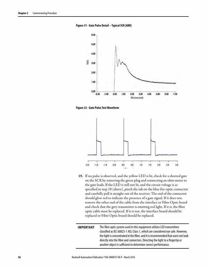
Chapter 2 Commissioning Procedure
Figure 31 - Gate Pulse Detail – Typical SCR (ABB)
Figure 32 - Gate Pulse Test Waveform
19. If no pulse is observed, and the yellow LED is lit, check for a shorted gate on the SCR by removing the green plug and connecting an ohm-meter to the gate leads. If the LED is still not lit, and the circuit voltage is as specified in step 18 (above), pinch the tab on the blue fire-optic connector and carefully pull it straight out of the receiver. The end of the connector should glow red to indicate the presence of a gate signal. If it does not, remove the other end of the cable from the interface or Fibre Optic board and check that the grey transmitter is emitting red light. If it is, the fibre optic cable must be replaced. If it is not, the interface board should be replaced or Fibre Optic board should be replaced.
IMPORTANT The fibre optic system used in this equipment utilizes LED transmitters classified as IEC 60825-1 AEL Class 1, which are considered eye safe. However, the light is concentrated in the fibre, and it is recommended that users not look directly into the fibre and connectors. Directing the light to a fingertip or another object is sufficient to determine correct performance.
Microseconds
Volts
56 Rockwell Automation Publication 7760-UM001F-EN-P - March 2016

Commissioning Procedure Chapter 2
20. When each gate-driver circuit has been checked, disconnect the power supply and remove it from the cabinet. Disconnect the current loop cable from the terminal blocks and lay it on the cart.
21. Open the switch SW2 on the interface board (Figure 27) before returning the unit to service. Ensure the red LED is off.
22. Remove the fiber optic cables from the fiber optic board and gently coil the cable bundle on the SCR Power truck to be racked in.
23. Replace the clear polycarbonate barriers on the SCR Power Truck and secure with two screws at the top and two screw at the bottom on both the front and the rear.
24. Carefully rack in the SCR Power Truck, connect all the fiber optic cables on the fiber optic board, and the temperature fiber optic cable to the bulkhead connector. Connect the current loop cables in the terminal blocks routing the cable through the ties provided.
25. Finally make the power connections with the flexible links to the Bus and torque to 20 lb•ft (27 N•m). Do not drop any hardware during the process of re-connecting the links.
ATTENTION: The clear barriers provide insulation between the converter module and the enclosure and unit Bus at the rear . They must be replaced before re-installing the converter modules. Failure to do so may result in arc faults which could result in burns, injury or death.
Rockwell Automation Publication 7760-UM001F-EN-P - March 2016 57

Chapter 2 Commissioning Procedure
Control Function Tests Perform the following tasks before performing the control function test.
1. The medium voltage to the incoming line unit is locked and tagged out.
2. The earthing switch on the bypass unit is closed.
3. The SCR Power Trucks are racked in and mechanically bolted in position.
4. The Power connections to SCR Power Truck are made and torqued to 14 N•m (11 lb•ft). The fiber optic connections on the fiber optic board are plugged in and the current loop wires are terminated.
5. The soft starter unit doors are closed in the required sequence as per interlock sequence.
6. The connector for control wiring of the bypass and main circuit breakers or contactors are plugged in.
7. The bypass and main circuit breakers or contactors are racked to the ‘Test’ position for the control function test.
Perform the following control function test.
1. Apply rated control voltage to the control circuit.
2. Using the control schematic, apply control signals to cause relays, circuit breakers or contactors to energize to verify operation.
3. Remove any jumpers used in the test and restore all circuits to normal when finished.
Voltage Sensing Module The voltage sensing module consists of a voltage sensing board and mounting plate (Figure 43). The voltage sensing board has six independent channels, with different sized resistors base on voltage range, which convert system voltages to low voltage levels that can be used by the SMC Flex control logic.
Table 6 shows the input voltage ranges for the voltage-sensing module. The output voltages are scaled to provide close to 10V peak for a 140% input voltage at the high end of each of the voltage ranges. Software will be used to scale the output to show the correct value on the SMC Flex front panel display. (see Parameter 106 – MV Ratio in Table 52 on page 131)
Table 6 - Input Voltage Ranges
Module-rated Voltage Voltage Range MV Ratio
12,000 10,000...12,000 126
14,400 12,001...15,000 97
58 Rockwell Automation Publication 7760-UM001F-EN-P - March 2016

Commissioning Procedure Chapter 2
The MV ratios shown above are nominal values and may be fine tuned to achieve better accuracy on the display of the SMC Flex control module. While running the motor in bypass mode, compare the voltage displayed on the control module to a known accurate meter connected to the same source voltage as the motor the MV SMC Flex is controlling. Parameter 106, MV Ratio, may be changed up or down to match the Flex display to the external meter. A small change in ratio can make a large change in the display, so 2 or 3 units at a time is recommended. Increasing the ratio will decrease the displayed voltage, and visa versa.
Start-Up 1. Remove any temporary jumpers or grounding devices used during commissioning.
2. Check that all tools are removed from the equipment. Any tools or hardware used or dropped during installation and commissioning must be retrieved.
3. All barriers or covers removed during installation or commissioning must be securely mounted.
4. Close and secure all doors, and verify function of all interlocks that prevent access to medium voltage compartments when the unit is energized.
5. If an earthing switch is provided, it must be opened before the apparatus can be inserted to the service position.
6. The controller is ready to power the motor.
Rockwell Automation Publication 7760-UM001F-EN-P - March 2016 59

Chapter 2 Commissioning Procedure
Notes:
60 Rockwell Automation Publication 7760-UM001F-EN-P - March 2016

Chapter 3
Programming
Overview This chapter provides a basic understanding of the programming keypad built into the SMC Flex controller. This chapter also describes programming the controller by modifying the parameters.
Keypad Description Table 7 - SMC Flex Controller Keys
For ease of programming values, after using the Enter key to edit, use the Sel key to jump to the digit that must be modified, then use the arrow keys to scroll through the digits.
Programming Menu Parameters are organized in a three-level menu structure for straightforward programming. Figure 33 details the programming menu structure and the three-level hierarchy.
To change parameters, the controller must be in the STOP mode, and the control voltage must be present.
IMPORTANT This manual pertains to the OneGear 10…15 kV SMC Flex control modules with version 6.003 firmware or later.
Key Action Description
Escape Exit a menu, cancel a change to a parameter value, or acknowledge a fault/alarm.
Select Select a digit, select a bit, or enter edit mode in a parameter screen. Will get to menu to change the language being displayed.
Up/Down Arrows
Scroll through options increase/decrease a value, or toggle a bit.
Enter Enter a menu, enter edit mode in a parameter screen, or save a change to a parameter value.
EscEsc
Lang SelSel
Rockwell Automation Publication 7760-UM001F-EN-P - March 2016 61

Chapter 3 Programming
Figure 33 - Menu Structure Hierarchy
DeviceParameter MemoryStorage Preferences DiagnosticsSelect
Choose Mode
Esc
Esc
Esc
Sel
LogIn�
LangEscEsc
EscEsc
EscEsc
SelSel
Lang
Power-up andStatus Display
Select language being displayed
Choose Mode
or
Parameter DeviceSelect
MemoryStorage Preferences Diagnostics
OPERATION LEVEL
MAIN MENU
or or or
GROUP MENU
LogIn
MonitoringSet UpMotor ProtectionCommunicationsUtilityLinear List
Rest to DefaultsSave to EEPROMRecall EEPROM
SMC Flex Change PasswordUser Dspl LineUser Dspl TimeUser Dspl VideoReset User Display
AlarmsFaultsDevice Revision
Parameter menuContinued in Figure 34
or
The SMC Flex controller does not support EEPROM, Link, Process, or Start-up modes.Steps back one level.Shown if password protection is configured.
62 Rockwell Automation Publication 7760-UM001F-EN-P - March 2016

Programming Chapter 3
Figure 34 - Parameter Menu Structure Hierarchy
Parameter
MotorSet Up UtilityProtection
Parameter
Monitoring Communications
EscParameter
EscEsc
Monitoring Set Up Communications Utility Linear ListMotor
Protection
Parameter
Jam
Underload F Lvl Underload F Dly Underload A Lvl Underload A Dly Parameter Mgt
Stall
Stall Dly Parameter Mgt
Ground Fault
SGnd Flt Enable Gnd Flt Lvl Gnd Flt Dly Gnd Flt Inh Time Gnd Flt A Enable Gnd Flt A Lvl Gnd Flt A Dly Parameter Mgt
PTC
PTC EnableParameter Mgt
Phase Reversal
Phase ReversalParameter Mgt
Restart
Starts Per Hour Restart AttemptsRestart Dly Parameter Mgt
Depending upon SMC option selected, some parameters may not appear in product display.Steps back one level.For further information on parameters, see Appendix B.For further information on parameter management, see page 66.
Metering Volts Phase A-BVolts Phase B-CVolts Phase C-ACurrent Phase ACurrent Phase B Current Phase C Watt Meter Megawatt Hours Elapsed Time Meter Reset Power Factor Mtr Therm Usage Motor Speed
Basic SMC OptionMotor ConnectionLine VoltageMV Ratio Starting Mode Ramp Time Initial Torque Cur Limit Lvl Kickstart Time Kickstart Lvl Stop Input Option 1 Input Option 2 Input Stop Mode Stop Time Braking Current Overload Class Service Factor Motor FLC CT Ratio Overload Reset Aux1 Config Aux2 Config Aux3 ConfigAux4 Config Backspin TimerParameter Mgt
Dual Ramp (Option 2 Input = Dual Ramp) Starting Mode 2 Ramp Time 2 Initial Torque 2 Cur Limit Lvl 2 Kickstart Time 2 Kickstart Lvl 2 Parameter Mgt
Preset SS (Option 2 Input = Preset SS) Slow Speed Sel Slow Speed Dir Slow Speed Acc Slow Running Cur Parameter Mgt
(Option 2 Input = Accu-Stop)
Braking Current Slow Speed Sel Slow Speed Dir Slow Accel Cur Slow Running Cur Stopping Current Parameter Mgt
Overload
Overload Class Service Factor Motor FLC Overload Reset Overload A Lvl Parameter Mgt
Underload
Underload F Lvl Underload F Dly Underload A Lvl Underload A Dly Parameter Mgt
Undervoltage
Underload F Lvl Underload F Dly Underload A Lvl Underload A Dly Parameter Mgt
Overvoltage
Underload F Lvl Underload F Dly Underload A Lvl Underload A Dly Parameter Mgt
Unbalance
Underload F Lvl Underload F Dly Underload A Lvl Underload A Dly Parameter Mgt
Comm Masks
Logic MaskParameter Mgt
Language
LanguageParameter Mgt
Linear List
All ParametersParameter Mgt
Motor Data
Motor Flc Motor ID CT Ratio MV Ratio Parameter Mgt
Data Links
Data In A1 Data In A2 Data In B1 Data In B2 Data In C1 Data In C2 Data In D1 Data In D2 Data Out A1 Data Out A2 Data Out B1 Data Out B2Data Out C1 Data Out C2 Data Out D1 Data Out D2 Parameter Mgt
Rockwell Automation Publication 7760-UM001F-EN-P - March 2016 63

Chapter 3 Programming
Table 8 - Parameter Linear List
Parameter No.
Description Parameter No.
Description Parameter No.
Description
1 Volts Phase A-B 46 Motor FLC 91 Data In B2
2 Volts Phase B-C 47 Overload Reset 92 Data In C1
3 Volts Phase C-A 48 OL Shunt Time 93 Data In C2
4 Current Phase A 49 OL Trip Enable 94 Data In D1
5 Current Phase B 50 Overload A Lvl 95 Data In D2
6 Current Phase C 51 Underload F Lvl 96 Data Out A1
7 Watt Meter 52 Underload F Dly 97 Data Out A2
8 Kilowatt Hours 53 Underload A Lvl 98 Data Out B1
9 Elapsed Time 54 Underload A Dly 99 Data Out B2
10 Meter Reset 55 Undervolt F Lvl 100 Data Out C1
11 Power Factor 56 Undervolt F Dly 101 Data Out C2
12 Mtr Therm Usage 57 Undervolt A Lvl 102 Data Out D1
13 Motor Speed 58 Undervolt A Dly 103 Data Out D1
14 SMC Option 59 Overvolt F Lvl 104 Motor ID
15 Motor Connection(1) 60 Overvolt F Dly 105 CT Ratio
16 Line Voltage 61 Overvolt A Lvl 106 MV Ratio
17 Starting Mode 62 Overvolt A Dly 107 Aux1 Config
18 Ramp Time 63 Unbalance F Lvl 108 Aux3 Config
19 Initial Torque 64 Unbalance F Dly 109 Aux4 Config
20 Cur Limit Level 65 Unbalance A Lvl 110 Aux2 Config
21 Reserved 66 Unbalance A Dly 111 Language
22 Kickstart Time 67 Jam F Lvl 112 Timed Start(1)
23 Kickstart Level 68 Jam F Dly 113 I Shutoff Level(1)
24 Option 2 Input 69 Jam A Lvl 114 UTS Level
25 Starting Mode 2 70 Jam A Dly 115 Parameter Mgmt
26 Ramp Time 2 71 Stall Delay 116 Backspin Timer
27 Initial Torque 2 72 Gnd Flt Enable 117 V Shutoff Level
28 Cur Limit Level 2 73 Gnd Flt Level 118 OL Reset Level
29 Reserved 74 Gnd Flt Delay 119 Ambient Temp(1)
30 Kickstart Time 2 75 Gnd Flt Inh Time 120 Notch Position(1)
31 Kickstart Level 2 76 Gnd Flt A Enable 121 Notch - Maximum (1)
32 Stop Mode 77 Gnd Flt A Lvl 122 Start Delay
33 Stop Time 78 Gnd Flt A Dly 123 Bypass Delay(1)
34 Pump Pedestal(2) 79 PTC Enable 124 Fault 1
35 Braking Current 80 Phase Reversal 125 Fault 2
36 Braking Time(3) 81 Starts Per Hour 126 Fault 3
37 Load Type(1) 82 Restart Attempts 127 Fault 4
38 High Eff Brake(1) 83 Restart Delay 128 Fault 5
64 Rockwell Automation Publication 7760-UM001F-EN-P - March 2016

Programming Chapter 3
Password The SMC Flex Controller allows you to limit access to the programming system through password protection. This feature is disabled with a factory-set default of 0. To modify the password or login after a password is programmed, complete the procedure detailed in Table 9.
Table 9 - Password Modification Procedure
39 Slow Speed Sel 84 Line Fault 129 Start Time E
40 Slow Speed Cur 85 Emergency Run 130 Start Time 2E
41 Slow Accel Cur 86 Current Loss 131 Stop Time E
42 Slow Running Cur 87 Logic Mask 132 Option 1 Input
43 Stopping Current 88 Data In A1 133 Stop Input
44 Overload Class 89 Data In A2 134 Elapsed Time 2
45 Service Factor 90 Data In B1
(1) Do not change these parameters from the default settings.
(2) Pump Control module only – see Troubleshooting section for guidance.
(3) Brake module only – Consult factory.
Table 8 - Parameter Linear List (Continued)
Parameter No.
Description Parameter No.
Description Parameter No.
Description
Description Action Display
— —
1. Press the ESC key to go from the status display to the Main menu.
2. Scroll with the Up/Down keys until the Preferences option is highlighted.
3. Press the Enter key to access the Preferences menu.
4. Scroll with the Up/Down keys until the Change Password option is highlighted.
—
5. Press the Enter key.
6. Press the Up/Down keys to enter the desired number. If you are modifying the password, make a note of it as displayed.
—
7. Verification of the new password is required. Press the Enter key.
—
8. Press the Enter key after you have completed modifying the password.(1)
(1) To complete the programming process, reenter the Main Menu mode to log out. This eliminates unauthorized access to the programming system.
EscEsc
Rockwell Automation Publication 7760-UM001F-EN-P - March 2016 65

Chapter 3 Programming
If you lose or forget the password, contact your nearest Rockwell Automation sales office. You can also call Rockwell Automation Medium Voltage Product Support at 1-519-740-4790 for assistance.
Parameter Management Before you begin programming, it is important to understand how the controller memory is structured within the SMC Flex controller, and used on power-up and during normal operation
Figure 35 - Memory Block Diagram
Random Access Memory (RAM)
This is the work area of the controller after it is powered up. The SMC Flex uses an Auto Store feature when programming parameters. When parameters are modified in the program mode, the new values are stored immediately in RAM and then in EEPROM, once the enter key has been pressed. If control power is lost before the enter key being pressed, these values are lost. When the device first powers up, the values from the EEPROM area of memory are copied into RAM.
Read-only Memory (ROM)
The SMC Flex controller comes with factory default parameter values. These settings are stored in non-volatile ROM and are displayed the first time that you enter the Program mode. At any time, you can restore defaults by accessing the memory storage menu.
Table 10 - SMC Flex Controller ROM Reset Procedure
Description Action Display
Recalling Defaults:After parameter values have been modified, factory default settings can still be re-initialized.
EscEsc SelSel
EEPROM RAM ROM
66 Rockwell Automation Publication 7760-UM001F-EN-P - March 2016

Programming Chapter 3
Electrically Erasable Programmable Read-only Memory (EEPROM)
The SMC Flex controller provides a non-volatile area for storing user-modified parameter values in the EEPROM.
Parameter Modification All parameters are modified using the same method. The basic steps to performing parameter modification are described below.
Notes:
1. Parameter values that are modified while the motor is operating are not valid until the next start sequence begins.
2. If the password is set, parameters cannot be adjusted without logging in.
3. Use the Sel key to highlight a single digit.
Table 11 - Parameter Modification Procedure
Description Action Display(2)
—
1. Press the ESC key to go from the status display to the Main menu.
—
2. Scroll with the Up/Down keys until the Preferences option is highlighted.
3. Press the Enter key to access the Parameter menu.
4. Scroll with the Up/Down keys until the option you want to use (Monitoring, Motor Protection, etc.) is highlighted. For this example, Set Up is used.
5. Press Enter to select the Set Up group.
—
6. Scroll to Basic Set Up and press Enter.(1)
7. Scroll to the Starting Mode parameter by using the Up/Down keys, and press Enter.
EscEsc
Rockwell Automation Publication 7760-UM001F-EN-P - March 2016 67

Chapter 3 Programming
Soft Start The following parameters are specifically used to adjust the voltage ramp supplied to the motor.
Table 12 - Soft Start Parameters and Options
Current Limit Start To apply a fixed, reduced-output voltage to the motor, the following parameters are provided for user adjustment.
8. Press Enter to select the option. Scroll to the option of your choice by using the Up/Down keys. For this example, we choose Current Limit.
9. Press the Enter key to accept the new setting.
—
10.Scroll to the next parameter by using the Down key. Continue the process until all desired settings are entered.
(1) The SMC Option advises the user if any control option (i.e., Pump Control) is resident. This parameter is factory set and cannot be modified by the user.
(2) To complete the programming process, reenter the Main Menu mode to log out. This eliminates unauthorized access to the programming system.
Table 11 - Parameter Modification Procedure (Continued)
Description Action Display(2)
Parameter Description Option
Starting Mode This must be programmed for soft start. Soft Start
Ramp Time(1)
(1) If the controller senses that the motor has reached full speed before completing the Soft Start, it automatically switches to providing full voltage to the motor.
Programs the time period that the controller ramps the output voltage up to full voltage from the initial Torque level programmed.
0...30 s(2)
(2) For ramp times greater than 30 s, set “Ramp Time” to zero and program “Ramp Time E” (parameter 129) to the new time. Do not exceed the thermal capacity of the controller.
Initial Torque The initial reduced output voltage level for the voltage ramp to the motor is established and adjusted with this parameter.
0...90% locked rotor torque
Kickstart Time A boost of current is provided to the motor for the programmed time period.
0.0...2.0 s
Kickstart Level Adjusts the amount of current applied to the motor during the kickstart time.
0...90% locked rotor torque
Table 13 - Current Limit Start Parameters and Options
Parameter Description Option
Starting Mode This must be programmed for Soft Start. Current Limit
Ramp Time(1) Programs the time period that the controller will ramp the output voltage up to full voltage from the initial Torque level programmed.
0...30 s(2)
68 Rockwell Automation Publication 7760-UM001F-EN-P - March 2016

Programming Chapter 3
Dual Ramp Start The SMC Flex controller provides the user with the ability to select between two Start settings. The parameters below are available in the Set Up programming mode. To obtain Dual Ramp control, Ramp #1 is located in the Basic Set Up and Ramp #2 is located in the Option 2 Input (Dual Ramp).
Current Limit Level
This parameter provides adjustability for the reduced output voltage level provided to the motor.
50...60% load current
Kickstart Time A boost of current is provided to the motor for the programmed time period.
0.0...2.0 s
Kickstart Level Adjusts the amount of current applied to the motor during the kickstart time.
0...90% locked rotor torque
(1) If the controller senses that the motor has reached full speed before completing the Soft Start, it will automatically switch to providing full voltage to the motor.
(2) For ramp times greater than 30 s, set “Ramp Time” to zero and program “Ramp Time E” (parameter 129) to the new time. Do not exceed the thermal capacity of the controller.
Table 13 - Current Limit Start Parameters and Options
Parameter Description Option
Table 14 - Dual Ramp Parameters and Options
Parameter Description Option
Set Up The user must select the Set-up programming mode to obtain access to the Dual Ramp parameters.
—
Basic Set-up/Starting Mode
Set-up as stated in previous pages. —
Option Input 2 (Dual Ramp) (1)
(1) The Dual Ramp feature is available on the standard controller.
This allows the user the option to choose between two Soft Start profiles defined by:1. Start Mode/Ramp Time/Initial Torque, and2. Start Mode 2/Ramp Time 2/Initial Torque 2.When this feature is turned on, the ramp time/initial torque combination is determined by a hard contact input to terminal 15. When this input signal is low, ramp time/initial torque are selected. When input signal is high, ramp time 2/initial torque 2 are selected. Once the Option 2 input has been set to Dual Ramp, you must ESC back to the Parameter (File) menu. Reenter into the Set Up menu to show both Basic Set Up and Dual Ramp.
—
Basic Set Up/Start Mode(2)
(2) Kickstart can be programmed for both start modes.
This selects the start mode for option #1. —
Basic Set-up/Ramp Time
This programs the time period during which the controller ramps the output voltage up to full voltage for the first Start set-up.
0...30 s
Basic Set-up/Initial Torque
This parameter establishes and adjusts the initial reduced output voltage level for the first Soft Start set-up.
0...90% locked rotor torque
Dual Ramp/Start Mode 2(2)
This selects the start motor for option #2. —
Dual Ramp/Ramp Time 2
This programs the time period during which the controller ramps the output voltage up to full voltage for the second Start set-up.
0...30 s(3)
(3) For ramp times greater than 30 s, set “Ramp Time 2” to zero and program “Start Time 2E” (parameter 130) for the new time. Do not exceed the thermal capacity of the controller.
Dual Ramp/Initial Torque 2
The initial reduced output voltage level for the second Start set-up is established and adjusted with this parameter.
0...90% locked rotor torque
Rockwell Automation Publication 7760-UM001F-EN-P - March 2016 69

Chapter 3 Programming
Full Voltage Start The SMC Flex controller can be programmed to provide a full voltage start (output voltage to the motor reaches full voltage within 1/4 second) with the following programming:
Table 15 - Full Voltage Start Parameter and Options
Linear Speed The SMC Flex provides the user the ability to control the motor speed during starting and stopping maneuvers. A tach input is required as specified in Linear Speed Acceleration and Deceleration on page 26. See Table 55 on page 142.
Stop Control The SMC Flex can be programmed to extend the motor stop time beyond the normal coast-to-rest time. There are two standard stop modes:
• Soft Stop• Linear Speed Deceleration.
Parameter Description Option
Starting Mode This must be programmed for Full Voltage. Full Voltage
Table 16 - Linear Speed Parameters and Options
Parameter Description Option
Starting Mode This must be programmed for Linear Speed. Linear Speed
Ramp Time(1)
(1) For ramp times greater than 30 s, set “Ramp Time” to zero and program “Ramp Time E” (parameter 129) to the new time. Do not exceed the thermal capacity of the controller.
Programs the time period that the controller ramps from 0 speed to full voltage.
0...30 s(1)
Kickstart Time A boost of current is provided to the motor for the programmed time period.
0.0...2.2 s
Kickstart Level Adjusts the amount of current applied to the motor during the kickstart time.
0...90% locked rotor torque
Table 17 - Stop Control Parameters and Options
Parameter Description Option
Stopping Mode This parameter can be set to one of two standard choices.(1)
(1) See Chapter 6 for optional stop control modes.
Soft StopLinear Speed(2)
(2) A motor tachometer is required (see page 26)
Stop Time Allows you to set the time period for the stopping function. 0…120 s(3)
(3) Consult factory if settings over 30 seconds are required. The base rating of the MV SMC-Flex is two starts (or one start/stop combination) per hour, 30 seconds maximum for each operation. A stopping operation counts as a start for purposes of thermal capacity calculations.
70 Rockwell Automation Publication 7760-UM001F-EN-P - March 2016

Programming Chapter 3
Preset Slow Speed This control mode can be configured to allow slow speed operation of the motor.
Basic Set-up The Basic Set-up programming group provides a limited parameter set, allowing quick start-up with minimal adjustments. If the user is planning to implement some of the advanced features, then the Linear List programming group should be selected. It provides all the Basic Setup parameter set plus the advanced set.
IMPORTANT Options that control the stopping of the motor (Soft Stop, Pump Stop, Linear Speed, Braking) require the self-powered gate drivers to be pre-charged by the current loop power supply. If this supply is not present, an alarm symbol will appear at the upper right corner of the control module display, and the options will be inhibited. When the motor is stopped, it will coast. If the supply is restored, the alarm symbol is cleared and the module performs the programmed sequence.
Table 18 - Preset Slow Speed Parameters and Options
Parameter Description Option
Slow Speed Select Allows you to program the slow speed that best fits the application.
Low: 7%–Forward10%–Reverse
High: 15%–Forward20%–Reverse
Slow Speed Direction This parameter programs the slow speed motor rotational direction.
Forward, Reverse
Slow Accel Current Allows the user to program the required current to accelerate the motor to slow speed operation.
0…450% of full load current
Slow Running Current Allows the user to program the required current to operate the motor at the slow speed setting.
0…450% of full load current
Table 19 - Basic Set-up Parameters and Options
Parameter Description Option
SMC Option Displays the type of controller. This is factory set and not adjustable. Standard
Motor Connection Displays the location of the SMC in relation to the motor windings. Line or Delta(4)
Line Voltage Displays the system line voltage the unit is connected to. —MV Ratio Scales the output from the Voltage Sensing Board to display correct
line voltage.1…1000(see Table 6 on page 58 Input Voltage Ranges)
Starting Mode Allows you to program the controller for the type of starting that best fits the application.
Soft Start, Current Limit, Full Voltage, Linear Speed
Ramp Time This parameter sets the time period during which the controller ramps the output voltage.
0…30 s
Initial Torque (1) The initial reduced voltage output level for the voltage ramp is established and adjusted with this parameter.
0…90% locked rotor torque
Current Limit Level (2)
The current limit level that is applied for the Ramp time selected. 50…600% FLC
Kickstart Time A boost current is provided to the motor for the programmed time period.
0.0…2.0 s
Rockwell Automation Publication 7760-UM001F-EN-P - March 2016 71

Chapter 3 Programming
Kickstart Level Adjusts the amount of current applied to the motor during kickstart. 0…90% locked rotor torque
Stop Input Allows you to select the operation of terminal 18, Stop Input. Coast, Stop Option
Option 1 Input Allows you to select the operation of terminal 16, Option Input #1. Disable, Stop Option, Fault, Fault NC, Network
Option 2 Input Allows you to select the operation of terminal 15, Option Input #2. Disable, Preset Slow Speed, Dual Ramp, Fault, Fault NC, Network, Clear Fault, Emergency Run (5)
Stop Mode Allows you to program the controller for the type of stopping that best fits the application.
Soft Stop, Linear Speed
Stop Time This parameter sets the time period that the controller ramps the voltage during a stopping maneuver.
0.0…120 s
CT Ratio Scales the CT input to actual motor current (5 amp secondary assumed).Example: CT Ratio = 150:5, program 150
1…1500
Aux1 Config(3) Contact is provided as standard with the controller. This contact is at terminals 19 and 20. Auxiliary Contact 1 allows you to configure the operation of the contacts.
Normal, Normal NC, Up-to-Speed, Up-to-Speed NC, Fault, Fault NC, Alarm, Alarm NC, Network, Network NC, External Bypass
Aux2 Config Contact is provided as standard with the controller. This contact is at terminals 29 and 30. Auxiliary Contact 2 allows you to configure the operation of the contacts.
Normal, Normal NC, Up-to-Speed, Up-to-Speed NC, Fault, Fault NC, Alarm, Alarm NC, Network, Network NC, External Bypass
Aux3 Config Contact is provided as standard with the controller. This contact is at terminals 31 and 32. Auxiliary Contact 3 allows you to configure the operation of the contacts.
Normal, Normal NC, Up-to-Speed, Up-to-Speed NC, Fault, Fault NC, Alarm, Alarm NC, Network, Network NC, External Bypass
Aux4 Config(3) Contact is provided as standard with the controller. This contact is at terminals 33 and 34. Auxiliary Contact 4 allows you to configure the operation of the contacts.
Normal, Normal NC, Up-to-Speed, Up-to-Speed NC, Fault, Fault NC, Alarm, Alarm NC, Network, Network NC, External Bypass
Parameter Mgmt Recall of factory default parameter values. Ready, Load Default
(1) Starting Mode must be programmed to Soft Start to obtain access to the Initial Torque parameter.
(2) Starting Mode must be programmed to Current Limit to obtain access to the Current Limit Level parameter.
(3) See the I/O section on page 36 and Notes on page 38 for MV specific functionality.
(4) This is not to indicate how the motor windings are configured. Do not select “Delta” for MV applications.
(5) When programmed for 'Emergency Run' and the Option 2 input is energized, a 'Start' command closes the bypass contactor, then the line contactor for an across-the-line start of the motor. A 'Stop' command opens the line contactor first and allow the motor to coast, regardless of the programmed 'Stop Mode'. For Pump Option modules, the Option 2 input defaults to 'Emergency Run' for MV applications.
Table 19 - Basic Set-up Parameters and Options (Continued)
Parameter Description Option
72 Rockwell Automation Publication 7760-UM001F-EN-P - March 2016

Programming Chapter 3
Motor Protection While the Basic Set Up group allows you to get started with a minimum number of parameters to modify, the Motor Protection group allows full access to the parameter set. Table 20 lists the additional setup parameters provided.
Most parameters have a Fault and an Alarm setting.
Table 20 - Motor Protection Parameters and Options
Parameter Description Option
Overload Allows you to select the operation of the overload. Trip Class, Service Factor, Motor FLC, Overload Reset, Overload Alarm Level
Underload (1)(2)
(1) The delay time must be set to a value greater than zero when Undervoltage, Overvoltage, and Unbalance are enabled.
(2) For Jam and Underload detection to function, the Motor FLC must be programmed in the Motor Protection group. See page 63.
Determines the trip level as a percentage of the motor's FLA, and the delay period.
Underload Fault Level, Underload Fault Delay, Underload Alarm Level, Underload Alarm Delay
Undervoltage(1) Determines the trip level as a percentage of line voltage and delay period.
Undervoltage Fault Level, Undervoltage Fault Delay, Undervoltage Alarm Level, Undervoltage Alarm Delay
Overvoltage(1) Determines the trip level as a percentage of line voltage and delay period.
Overvoltage Fault Level, Overvoltage Fault Delay, Overvoltage Alarm Level, Overvoltage Alarm Delay
Unbalance(1) Allows you to set the current unbalance trip level and delay period. Unbalance Fault Level, Unbalance Fault Delay, Unbalance Alarm Level, Unbalance Alarm Delay
Jam (1)(2) Determines the trip level as a percentage of motor full load current and delay period.
Jam Fault Level, Jam Fault Delay, Jam Alarm Level, Jam Alarm Delay
Stall Allows you to set the stall delay time. Stall Delay
Ground Fault Allows you to enable the ground fault level in amps, delay time and inhibit time. A separate core balance current transformer is required.
Ground Fault Enable, Ground Fault Level, Ground Fault Delay, Ground Fault Inhibit Time, Ground Fault Alarm Enable, Ground Fault Alarm Level, Ground Fault Alarm Delay
PTC Allows you to connect a PTC to the SMC and enable a fault when it becomes active.
PTC Enable
Phase Reversal Determines the proper orientation of line connections to the SMC. If Enabled and phases are out of sequence, a fault is indicated.
Phase Reversal
Restarts Allows you to determine the maximum number of restarts per hour the unit can experience, and delay time between consecutive starts.
Restarts Per Hour, Restart Attempts, Restart Delay
Rockwell Automation Publication 7760-UM001F-EN-P - March 2016 73

Chapter 3 Programming
Example Settings Undervoltage(1)
With Line Voltage programmed for 11,000V and the Undervoltage level programmed for 80%, the trip value is 8800V.
Overvoltage(1)
With Line Voltage programmed for 13,800V and the Overvoltage level programmed for 115%, the trip value is 15,870V.
Jam(2)
With Motor FLC programmed for 150 A and the Jam level programmed for 400%, the trip value is 600 A.
Underload(2)
With Motor FLC programmed for 90 A and the Underload level programmed for 60%, the trip value is 54 A.
(1) The average value of the three phase-to-phase voltages is utilized.
(2) The largest value of the three phase currents is utilized.
74 Rockwell Automation Publication 7760-UM001F-EN-P - March 2016
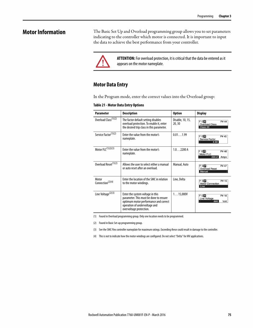
Programming Chapter 3
Motor Information The Basic Set Up and Overload programming group allows you to set parameters indicating to the controller which motor is connected. It is important to input the data to achieve the best performance from your controller.
Motor Data Entry
In the Program mode, enter the correct values into the Overload group:
ATTENTION: For overload protection, it is critical that the data be entered as it appears on the motor nameplate.
Table 21 - Motor Data Entry Options
Parameter Description Option Display
Overload Class(1)(2)
(1) Found in Overload programming group. Only one location needs to be programmed.
(2) Found in Basic Set-up programming group.
The factor default setting disables overload protection. To enable it, enter the desired trip class in this parameter.
Disable, 10, 15, 20, 30
Service Factor(1)(2) Enter the value from the motor’s nameplate.
0.01…1.99
Motor FLC(1)(2)(3)
(3) See the SMC Flex controller nameplate for maximum ratings. Exceeding these could result in damage to the controller.
Enter the value from the motor’s nameplate.
1.0…2200 A
Overload Reset(1)(2) Allows the user to select either a manual or auto reset after an overload.
Manual, Auto
Motor Connection(2)(4)
(4) This is not to indicate how the motor windings are configured. Do not select “Delta” for MV applications.
Enter the location of the SMC in relation to the motor windings.
Line, Delta
Line Voltage(2)(3) Enter the system voltage in this parameter. This must be done to ensure optimum motor performance and correct operation of undervoltage and overvoltage protection.
1…15,000V
Rockwell Automation Publication 7760-UM001F-EN-P - March 2016 75

Chapter 3 Programming
Notes:
76 Rockwell Automation Publication 7760-UM001F-EN-P - March 2016

Chapter 4
Metering
Overview While the SMC Flex controller operates your motor, it also monitors several different parameters, providing a full function metering package.
Viewing Metering Data To access the metering information, follow the procedure in Table 22.
Table 22 - Viewing Metering Data Procedure
Description Action Display
—
1. To access the Main menu, press any key.
2. Scroll with the Up/Down keys until the Parameter option is shown.
3. To access the Parameter option, press the Enter key.
—
4. Scroll with the Up/Down keys until the Monitoring option is displayed.
EscEsc
Rockwell Automation Publication 7760-UM001F-EN-P - March 2016 77

Chapter 4 Metering
See Metering on page 36 or Figure 34 on page 63 for details on the metering functions.
The metering values that are displayed on the controller can be modified to show you desired values by accessing Main Menu / Preferences.
5. To access the Monitoring group, press the Enter key.
—
6. To access the Metering group, press the Enter key.
7. To access the desired information, scroll through the Metering parameters with the Up/Down keys. To view a parameter, press the Enter key.
Table 22 - Viewing Metering Data Procedure (Continued)
Description Action Display
78 Rockwell Automation Publication 7760-UM001F-EN-P - March 2016
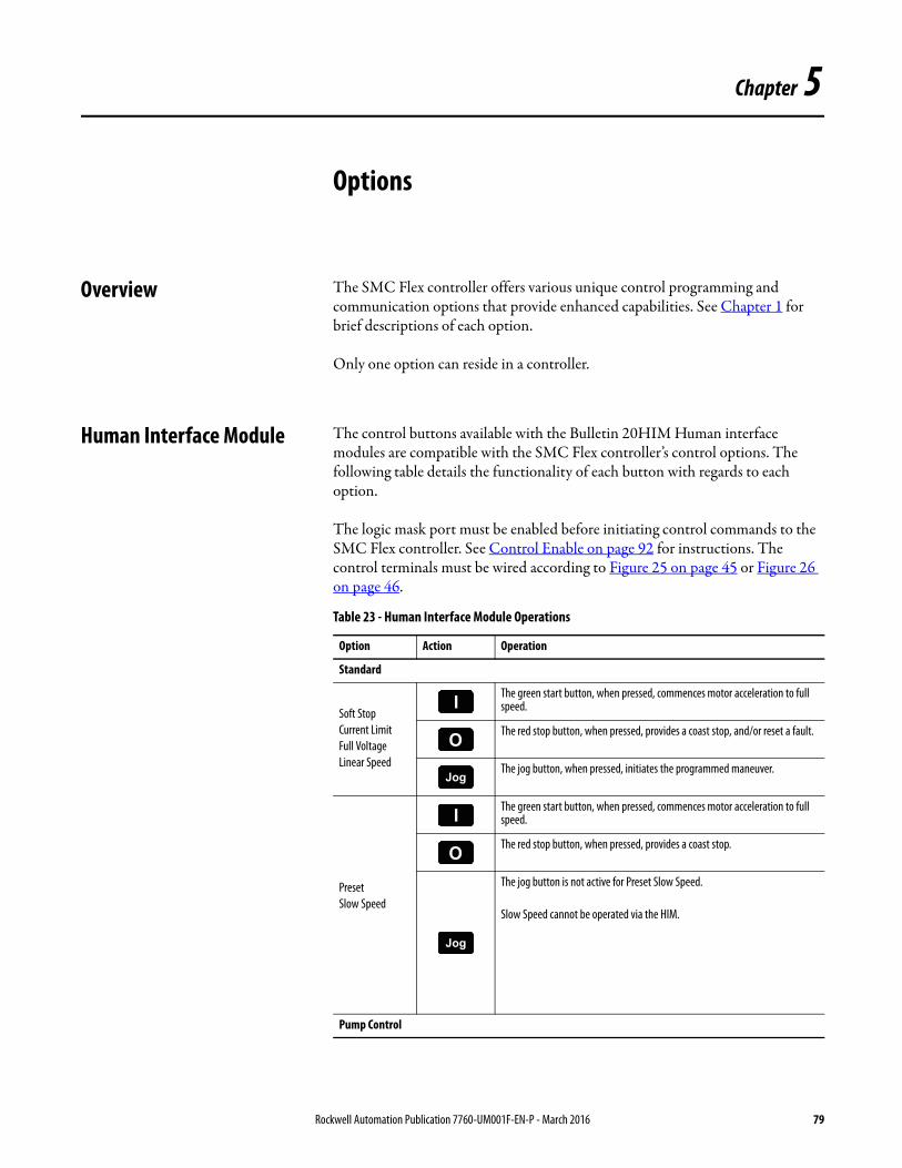
Chapter 5
Options
Overview The SMC Flex controller offers various unique control programming and communication options that provide enhanced capabilities. See Chapter 1 for brief descriptions of each option.
Only one option can reside in a controller.
Human Interface Module The control buttons available with the Bulletin 20HIM Human interface modules are compatible with the SMC Flex controller’s control options. The following table details the functionality of each button with regards to each option.
The logic mask port must be enabled before initiating control commands to the SMC Flex controller. See Control Enable on page 92 for instructions. The control terminals must be wired according to Figure 25 on page 45 or Figure 26 on page 46.
Table 23 - Human Interface Module Operations
Option Action Operation
Standard
Soft StopCurrent LimitFull VoltageLinear Speed
The green start button, when pressed, commences motor acceleration to full speed.
The red stop button, when pressed, provides a coast stop, and/or reset a fault.
The jog button, when pressed, initiates the programmed maneuver.
PresetSlow Speed
The green start button, when pressed, commences motor acceleration to full speed.
The red stop button, when pressed, provides a coast stop.
The jog button is not active for Preset Slow Speed. Slow Speed cannot be operated via the HIM.
Pump Control
II
OO
JogJog
II
OO
JogJog
Rockwell Automation Publication 7760-UM001F-EN-P - March 2016 79
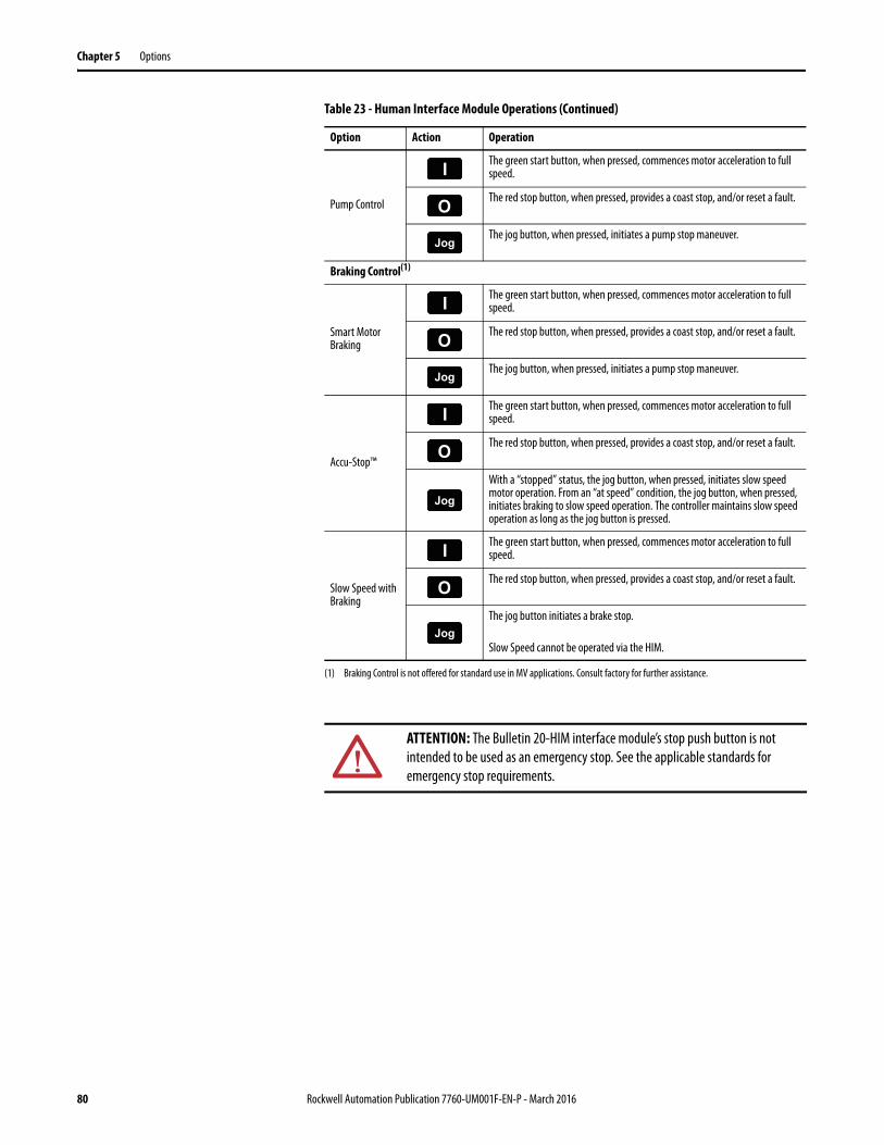
Chapter 5 Options
Pump Control
The green start button, when pressed, commences motor acceleration to full speed.
The red stop button, when pressed, provides a coast stop, and/or reset a fault.
The jog button, when pressed, initiates a pump stop maneuver.
Braking Control(1)
Smart Motor Braking
The green start button, when pressed, commences motor acceleration to full speed.
The red stop button, when pressed, provides a coast stop, and/or reset a fault.
The jog button, when pressed, initiates a pump stop maneuver.
Accu-Stop™
The green start button, when pressed, commences motor acceleration to full speed.
The red stop button, when pressed, provides a coast stop, and/or reset a fault.
With a “stopped” status, the jog button, when pressed, initiates slow speed motor operation. From an “at speed” condition, the jog button, when pressed, initiates braking to slow speed operation. The controller maintains slow speed operation as long as the jog button is pressed.
Slow Speed with Braking
The green start button, when pressed, commences motor acceleration to full speed.
The red stop button, when pressed, provides a coast stop, and/or reset a fault.
The jog button initiates a brake stop. Slow Speed cannot be operated via the HIM.
(1) Braking Control is not offered for standard use in MV applications. Consult factory for further assistance.
ATTENTION: The Bulletin 20-HIM interface module’s stop push button is not intended to be used as an emergency stop. See the applicable standards for emergency stop requirements.
Table 23 - Human Interface Module Operations (Continued)
Option Action Operation
II
OO
JogJog
II
OO
JogJog
II
OO
JogJog
II
OO
JogJog
80 Rockwell Automation Publication 7760-UM001F-EN-P - March 2016

Options Chapter 5
Programming Parameters The following table provides the option-specific parameters that are provided with each control option. These parameters are in addition to those already discussed in the Basic Set Up and Metering groups. Diagrams which support the options described below are shown later in this chapter.
Option Parameter Range
Pump Control
Pump Control
SMC OptionThis parameter identifies the type of control present and is not programmable.
Pump Control
Pump Stop TimeAllows you to set the time period for the pump stopping function.
0...120 s
Starting ModeAllows you to program the SMC-Flex controller for the type of starting that best fits the application.
Pump Start, Soft Start, Current Limit Start, Full Voltage
Braking Control(1)
(1) Braking Control is not offered for standard use in MV applications. Consult factory for further assistance.
SMB Smart Motor Braking
SMC OptionThis parameter identifies the type of control present and is not programmable.
Braking Control
Braking Current(2)
Allows you to program the intensity of the braking current that is applied to the motor.
(2) All braking/stopping current settings in the range of 1…100% provide 100% braking current to the motor.
0…400% of full load current
Accu-Stop
SMC OptionThis parameter identifies the type of control present and is not user programmable.
Braking Control
Slow Speed SelectAllows you to program the slow speed that best fits the application.
Low: 7%High: 15%
Slow Accel CurrentAllows you to program the required current to accelerate the motor to slow speed operation.
0…450% of full load current
Slow Running CurrentAllows you to program the required current to operate the motor at slow speed operation.
0…400% of full load current
Braking Current Allows you to program the intensity of the braking current applied to the motor.
0…400% of full load current
Stopping Current Allows you to program the intensity of the braking current applied to the motor from slow speed operation.
0…400% of full load current
Slow Speed with Braking
SMC OptionThis parameter identifies the type of control present and is not user programmable.
Braking Control
Slow Speed SelectAllows you to program the slow speed that best fits the application.
Low: 7%High: 15%
Slow Accel CurrentAllows you to program the required current to accelerate the motor to slow speed operation.
0…450% of full load current
Slow Running CurrentAllows you to program the required current to operate the motor at the slow speed setting.
0…450% of full load current
Braking Current Allows you to program the intensity of the braking current that is applied to the motor.
0…400% of full load current
Rockwell Automation Publication 7760-UM001F-EN-P - March 2016 81

Chapter 5 Options
Options that control the stopping of the motor (Soft Stop, Pump Stop, Linear Speed, Braking) require the self-powered gate drivers to be pre-charged by the current loop power supply. If this supply is not present, an alarm symbol appears at the upper right corner of the control module display, and the options are inhibited. When the motor is stopped, it will coast. If the supply is restored, the alarm symbol is cleared and the module performs the programmed sequence.
Control Wiring See Chapter 1 for typical control wiring examples that are used with various control schemes.
82 Rockwell Automation Publication 7760-UM001F-EN-P - March 2016

Chapter 6
Diagnostics
Overview This chapter describes the fault diagnostics of the controller. Further, this section describes the conditions that cause various faults to occur.
Protection Programming
Many of the protective features available with the controller can be enabled and adjusted through the programming parameters provided. For further details on programming, see the Motor Protection section in Chapter 3.
Fault Display The controller comes equipped with a built-in three-line, 16-character LCD. The LCD displays the fault message on the first line, the fault code on the second line, and the fault description on the third line.
Figure 36 - Fault Display
The fault display remains active as long as control power is applied. If control power is cycled, the fault is cleared, the controller reinitializes, and the display shows a status of "Stopped".
Press ESC to get to another programming/diagnostic list. The controller remains in a faulted state.
IMPORTANT Resetting a fault does not correct the cause of the fault condition. Corrective action must be taken before resetting the fault.
Rockwell Automation Publication 7760-UM001F-EN-P - March 2016 83

Chapter 6 Diagnostics
Clear Fault You can clear a fault using several methods:
Press and hold the front panel “ESC” key for 3 seconds.
Program the SMC Flex controller for a Clear Fault, which can be found in Main Menu/Diagnostics/Faults.
If a human interface module is connected to the controller, press the Stop button.
If a RESET push button is present, the N.O. push button auxiliary contact can be connected to Option Input #2 (terminal 15). Option Input #2 must be programmed for Clear Fault.
Cycle control power to the SMC Flex controller.
Fault Buffer The SMC Flex controller stores in memory the five most recent faults. Display the fault buffer by selecting the View Faults Queue and scroll through the fault buffer parameters. The information is stored as fault codes and fault descriptions. A fault code cross-reference is provided in Table 24.
Complete MV SMC Flex controllers are factory-tested to prove fault trip functions, so the Fault Buffer may already have fault codes in the queue.
Fault Codes
Table 24 provides a complete cross-reference of the available fault codes and corresponding fault descriptions.
TIP A stop signal from the HIM always stops the motor and clears the fault, regardless of Logic Mask configuration.
IMPORTANT An overload fault cannot be reset until the Motor Thermal Usage, parameter 12, value is below 75%. See Protection and Diagnostics on page 28 for further details.
Table 24 - Fault Code Cross-Reference
Fault Code Fault Code
Line Loss A 1 Stall 25
Line Loss B 2 Phase Reversal 26
Line Loss C 3 Coms Loss P2 27
Shorted SCR A 4 Coms Loss P3 28
Shorted SCR B 5 Coms Loss P5 29
Shorted SCR C 6 Network P2 30
Open Gate A 7 Network P3 31
Open Gate B 8 Network P5 32
84 Rockwell Automation Publication 7760-UM001F-EN-P - March 2016
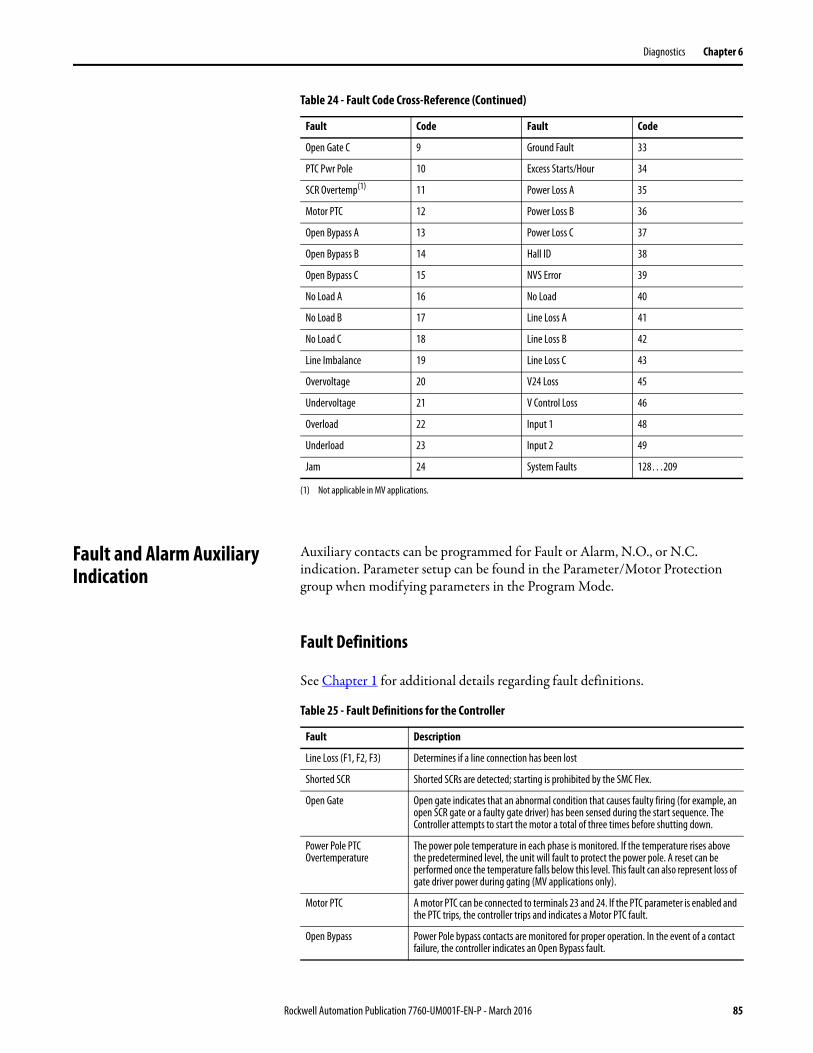
Diagnostics Chapter 6
Fault and Alarm Auxiliary Indication
Auxiliary contacts can be programmed for Fault or Alarm, N.O., or N.C. indication. Parameter setup can be found in the Parameter/Motor Protection group when modifying parameters in the Program Mode.
Fault Definitions
See Chapter 1 for additional details regarding fault definitions.
Table 25 - Fault Definitions for the Controller
Open Gate C 9 Ground Fault 33
PTC Pwr Pole 10 Excess Starts/Hour 34
SCR Overtemp(1) 11 Power Loss A 35
Motor PTC 12 Power Loss B 36
Open Bypass A 13 Power Loss C 37
Open Bypass B 14 Hall ID 38
Open Bypass C 15 NVS Error 39
No Load A 16 No Load 40
No Load B 17 Line Loss A 41
No Load C 18 Line Loss B 42
Line Imbalance 19 Line Loss C 43
Overvoltage 20 V24 Loss 45
Undervoltage 21 V Control Loss 46
Overload 22 Input 1 48
Underload 23 Input 2 49
Jam 24 System Faults 128…209
(1) Not applicable in MV applications.
Table 24 - Fault Code Cross-Reference (Continued)
Fault Code Fault Code
Fault Description
Line Loss (F1, F2, F3) Determines if a line connection has been lost
Shorted SCR Shorted SCRs are detected; starting is prohibited by the SMC Flex.
Open Gate Open gate indicates that an abnormal condition that causes faulty firing (for example, an open SCR gate or a faulty gate driver) has been sensed during the start sequence. The Controller attempts to start the motor a total of three times before shutting down.
Power Pole PTC Overtemperature
The power pole temperature in each phase is monitored. If the temperature rises above the predetermined level, the unit will fault to protect the power pole. A reset can be performed once the temperature falls below this level. This fault can also represent loss of gate driver power during gating (MV applications only).
Motor PTC A motor PTC can be connected to terminals 23 and 24. If the PTC parameter is enabled and the PTC trips, the controller trips and indicates a Motor PTC fault.
Open Bypass Power Pole bypass contacts are monitored for proper operation. In the event of a contact failure, the controller indicates an Open Bypass fault.
Rockwell Automation Publication 7760-UM001F-EN-P - March 2016 85

Chapter 6 Diagnostics
No Load The controller can determine if a load connection has been lost, and No Load fault is indicated.
Line Unbalance(1) Voltage unbalance is detected by monitoring the three-phase supply voltages. The formula that is used to calculate the percentage voltage unbalance is as follows:• Vu = 100 (Vd / Va)• Vu: Percent voltage unbalance• Vd: Maximum voltage deviation from the average voltage• Va: Average voltageThe controller shuts down when the calculated voltage unbalance reaches the user-programmed trip percentages.
Overvoltage and Undervoltage Protection(1)
Overvoltage and undervoltage protection are user-defined as a percentage of the programmed line voltage. The controller continuously monitors the three supply phases. The calculated average is then compared to the programmed trip level.
Underload(2) Underload protection is available for undercurrent monitoring. The controller shuts down when the motor current drops below the trip level. This trip level, a percentage of the motor’s full load current rating, can be programmed.
Overload Protection Overload protection is enabled in the motor protection group by programming the:• Overload class• Overload reset• Motor FLC• Service factorSee page 73 for more information on motor protection.
Phase Reversal Phase reversal is indicated when the incoming power to the controller is in any sequence other than ABC. This pre-start protective feature can be disabled.
Coms Loss The SMC Flex controller disables control through the serial communication port as the factory default. To enable control, the Logic Mask that is found in the Communication programming group must be set to “4.” With Series B human interface modules, this can also be accomplished by enabling control logic through the Control Status programming group.If a Bulletin 20-HIM Human interface module or Bulletin 1203 communication module is disconnected from the SMC Flex controller when control is enabled, a Comm Fault occurs. Other settings could cause this fault (see Table 39).
Network Network faults are faults that are generated on the network external to the controller, and are annunciated on the LCD display.
Ground Fault Ground faults are based on feedback from the user-supplied 825 CT detecting ground fault currents. Ground fault parameters of level and time delay must be programmed for proper operation.
Excess Starts/Hour Excess starts/hour is displayed when the number of starts in a 1-hour period exceeds the value that is programmed.
Power Loss Power loss indicates that an input power phase is not present. The LCD display identifies the missing phase. If all three phases are absent when a start command is issued, the LCD displays “Starting” without motor rotation.
Line Loss (F41, F42, F43) During expected SCR gate periods, the power pole voltage and currents are monitored. If the SCR conduction is not continuous, a fault is indicated.
(1) Phase loss, overvoltage, and undervoltage protection are disabled during braking operation.
(2) Jam detection and underload protection are disabled during slow speed and braking operation.
Fault Description
86 Rockwell Automation Publication 7760-UM001F-EN-P - March 2016

Chapter 7
Communication
Overview The controller provides advanced communication capabilities that allow it to be started and stopped from multiple sources and provide diagnostic information by using communication interfaces. The controller uses the DPI™ method of communication, therefore all standard DPI communication interfaces that are used by other devices (for example, PowerFlex® drives) can be used in the controller. ScanPort devices are not supported by the controller.
Standard DPI communication cards are available for various protocols including DeviceNet, ControlNet, Remote I/O, ModBus™, and Profibus® DP. Other modules can be available in the future. For specific programming examples, configuration, or programming information, see the user manual for the communication interface being used. Table 26 lists available interfaces.
Communication Ports The SMC supports three DPI ports for communication. Ports 2 and 3 are supported through the serial connection on the side of the device and are typically used to interface with a Human Interface Module (HIM). Port 2 is the default connection with port 3 available by installing a splitter on port 2. Port 5 is supported by connecting one of the modules that are listed in Table 26 to the internal DPI comm card connection.
Table 26 - Communication Interfaces
Protocol Type Cat. No. User Manual
DeviceNet 20-COMM-D 20COMM-UM002
ControlNet 20-COMM-C 20COMM-UM003
Remote I/O 20-COMM-R 20COMM-UM004
Profibus 20-COMM-P 20COMM-UM006
RS-485 20-COMM-S 20COMM-UM005
InterBus 20-COMM-I 20COMM-UM007
EtherNet/IP 20-COMM-E 20COMM-UM010
RS485 HVAC 20-COMM-H 20COMM-UM009
LonWorks 20-COMM-L 20COMM-UM008
ControlNet (Fiber) 20-COMM-Q 20COMM-UM003
Rockwell Automation Publication 7760-UM001F-EN-P - March 2016 87

Chapter 7 Communication
Human Interface Module The SMC Flex controller can be programmed with the built-in keypad and LCD display or with the optional Bulletin 20HIM LCD human interface modules. Parameters are organized in a three-level menu structure and divided into programming groups.
Node addressing of the DPI communication card can be programmed via software or a hand-held DPI HIM. The onboard HIM cannot be used to address the communication card.
Keypad Description
The functions of each programming key are described in Table 27.
For ease of programming values, after using the Enter key to edit, use the Sel key to jump to the digit that must be modified. Then use the arrow keys to scroll through the digits.
The Bulletin 20-HIM LCD interface modules may be used to program and control the SMC Flex controller. The human interface modules have two sections: a display panel and a control panel. The display panel duplicates the 3-line, 16-character backlit LCD display, and programming keypad that is found on front of the SMC Flex controller. See Chapter 7 for a description of the programming keys; see page 143 for a listing of human interface module catalog numbers that are compatible with the controller.
Bulletin 20-HIM Rev3.002 or later must be used with the SMC Flex.
Extension cables are available up to a maximum of 10 m (32.8 ft).
A maximum of two HIM modules can be installed.
The control panel provides the operator interface to the controller.
Table 27 - Keypad Descriptions
Key Name Description
Escape Exit a menu, cancel a change to a parameter value, or acknowledge a fault/alarm.
Select Select a digit, select a bit, or enter edit mode in a parameter screen.
Up/Down ArrowsScroll through options increase/decrease a value, or toggle a bit.
Enter Enter a menu, enter edit mode in a parameter screen, or save a change to a parameter value.
TIP If a human interface module is disconnected from the SMC Flex controller while the Logic Mask is set to 1, a “Coms Loss” occurs.
EscEsc
SelSel
88 Rockwell Automation Publication 7760-UM001F-EN-P - March 2016

Communication Chapter 7
All other controls available with the various human interface modules are non-functional with the controller.
Connecting the Human Interface Module to the Controller
Figure 37 shows the connection of the SMC Flex controller to a human interface module. Table 29 provides a description of each port.
The controller only supports the use of DPI communication modules and DPI HIM Modules. SMC Flex does not support scanport devices.
See Figure 25 on page 45 or Figure 26 on page 46 for the control wiring diagram that enables start-stop control from a human interface module.
Table 28 - Operator Interface Keys
Key Name Description
Start The green start button, when pressed, begins motor operation. (Proper setup of HIM port is required.)
Stop The red stop button, when pressed, halts motor operation and/or reset a fault.
Jog The jog button is active only when a control option is present. Pressing the jog button initiates the option maneuver (for example: Pump Stop).
ATTENTION: The Bulletin 20-HIM interface module's stop push button is not intended to be used as an emergency stop. See the applicable standards for emergency stop requirements.
ATTENTION: The external HIM has a similar programming operation to the built-in programmer, but note that differences do exist.
II
OO
JogJog
Rockwell Automation Publication 7760-UM001F-EN-P - March 2016 89

Chapter 7 Communication
Figure 37 - SMC Flex Controller with Human Interface Module Connected
HIM Control Enable
To enable motor control from a connected human interface module, follow the procedure with the connected human interface module’s programming keys.
The Bulletin 20-HIM-LCD human interface modules with control panels can start and stop the controller. However, the factory default settings disable control commands other than Stop through the serial communication port.
To enable motor control from a connected human interface module or communication module, you must take the following programming steps:
1. Disconnect the HIM and allow to power down.
2. Reconnect the HIM. On Initializing screen, the bottom right corner of LCD shows Port X. Note this port number.
Port 5 – DPI Communications
Port 2
Ports 2 and 3 when two HIMsare connected with a splitter
Table 29 - Description of Ports
Port # Description
1 Unused – Not available for use
2 First 20-HIM connected to SMC Flex
3 Second 20-HIM connected to SMC Flex
5 DPI Communication Board port
90 Rockwell Automation Publication 7760-UM001F-EN-P - March 2016

Communication Chapter 7
Figure 38 - Port Number Displayed
3. Navigate to Parameter/Communications/Comm Mask/Logic Mask.
Figure 39 - Logic Mask Displayed
4. Set b0X equal to 1 (where X is the port number noted in step 2).
5. Go to Parameter Management and save as User Store.
If enabling control from the built-in SMC Flex programmer, the Logic Mask must be set as follows:
IMPORTANT The Logic Mask must be set to 0 before disconnecting a human interface module from the SMC Flex controller. If not, the unit will fault on a “Coms Loss”.
Table 30 - Logic Mask Requirements
Mask Code Description
0 No external DPI devices are enabled
4 Only one HIM on port 2 is enabled
12 Two HIMs are enabled on ports 2 and 3
32 Only the DPI communication card on port 5 is enabled
36 One HIM on port 2 and the DPI communication card on port 5 are enabled
44 Two HIMs on ports 2 and 3 and the DPI communication card on port 5 are enabled
Rockwell Automation Publication 7760-UM001F-EN-P - March 2016 91

Chapter 7 Communication
Control Enable The Logic Mask parameter (Parameter 87) allows you to configure whether a communication device (HIM or network connection) can perform control commands such as starting. Each communication port can be enabled or disabled as required. When a given device is enabled through the logic mask that device is allowed to execute control commands. In addition, disconnecting any device with the logic mask enabled results in a communication fault unless the communication fault is disabled. When a given device is disabled through the logic mask that device cannot execute control commands, but can still be used for monitoring. A device that is disabled through the logic mask can be disconnected without causing a fault.
Loss of Communication and Network Faults
The loss of communication fault follows the functionality as defined in the DPI specification. There are separate faults for each device. Since three DPI ports are supported, there are three faults that can be generated.
DPI provides a separate network fault for each port. This fault can be generated directly using the peripheral and is separate from the Communications Loss fault (which is generated by the SMC Flex itself ).
SMC Flex Specific Information
The SMC can be used with all LCD applicable DPI interface. Regardless of the type of interface being used, the information below can be used to configure the rest of the system.
Default Input/Output Configuration
The default configuration for I/O is 4 bytes in and 4 bytes out (TX = 4 bytes, RX = 4 bytes). The total size can very when used with a communication card. The default configuration is arranged according to the following table.
Table 31 - Default Input/Output Configuration
The total size that is produced or consumed varies, depending on the communication card being used. For more information, see the user manual for the communication card.
IMPORTANT Stop commands override all start commands and can be initiated from the hardwired inputs or any port regardless of the logic mask.
Parameter Produced Data (Status) Consumed Data (Control)
Word 0 Logic Status Logic Command
Word 1 Feedback(1)
(1) The feedback word is always Current in Phase A.
Reference(2)
(2) The reference word is not used with the SMC Flex; however, the space must be reserved.
92 Rockwell Automation Publication 7760-UM001F-EN-P - March 2016

Communication Chapter 7
Variable Input/Output Configuration
The controller supports 16 b Datalinks, so the device can be configured to return additional information. The I/O message size depends on how many Datalinks are enabled. Table 32 summarizes the I/O data sizes.
To configure Datalinks, see Configuring Datalinks on page 97.
Table 32 - Variable Input/Output Configuration
Rx Size Tx Size Logical Status/Command (16 b)
Reference/Feedback (16 b)
Data Links
A B C D
4 4 X X
8 8 X X X
12 12 X X X X
16 16 X X X X X
20 20 X X X X X X
Rockwell Automation Publication 7760-UM001F-EN-P - March 2016 93

Chapter 7 Communication
SMC Flex Bit Identification
Table 33 - Logic Status Word
Bit #Status Description
15 14 13 12 11 10 9 8 7 6 5 4 3 2 1 0
X Enabled1 – Control Power Applied0 – No Control Power
X Running1 – Power Applied to Motor0 – Power not Applied to Motor
X Phasing1 – ABC Phasing0 – CBA Phasing
X PhasingActive
1 – 3-phase is valid0 – No valid 3-phase is detected
X Starting(Accel)
1 – Performing a Start Maneuver0 – Not performing a Start Maneuver
X Stopping(Decel)
1 – Performing a Start Maneuver0 – Not performing a Start Maneuver
X Alarm1 – Alarm Present0 – No Alarm Present
X Fault1 – Fault Condition Exists0 – No Fault Condition
X At Speed1 – Full Voltage Applied0 – Not Full Voltage Applied
X Start/Isolation
1 – Start/Isolation Contactor Enabled0 – Start/Isolation Contactor Disabled
X Bypass1 – Bypass Contactor Enabled0 – Bypass Contactor Disabled
X Ready1 – Ready0 – Not Ready
X X Option 1Input
1 – Input Active0 – Input Inactive
X X Option 2Input
1 – Input Active0 – Input Inactive
— — Bits 12 to 15 – Not Used
94 Rockwell Automation Publication 7760-UM001F-EN-P - March 2016

Communication Chapter 7
Table 34 - Logic Status Word (Control)
Reference/Feedback The SMC Flex does not offer the analog Reference feature. The analog Feedback feature is supported and provides Parameter1, Current in Phase A, automatically as the feedback word.
Parameter Information A complete listing of the SMC Flex parameters is located on page 131.
Bit #Status Description
15 14 13 12 11 10 9 8 7 6 5 4 3 2 1 0
X Stop1 – Stop/Inhibit0 – No/Action
X Start1 – Start0 – No Action
X Option #1 Input
1 – Stop Maneuver/Inhibit (Option Stop)0 – No Action
X Clear Faults
1 – Clear Faults0 – No Action
X Option #2 Input
1 – Perform Option 2 function0 – No Action
— — Bits 5…10 – Not Used
X Aux Enable
1 – Use Aux 1 to Aux 40 – Ignore Aux 1 to Aux 4
X Aux 11 – Aux 1 Active0 – Aux 1 Inactive
X Aux 21 – Aux 2 Active0 – Aux 2 Inactive
X X Aux 31 – Aux 3 Active0 – Aux 3 Inactive
X X Aux 41 – Aux 4 Active0 – Aux 4 Inactive
Rockwell Automation Publication 7760-UM001F-EN-P - March 2016 95
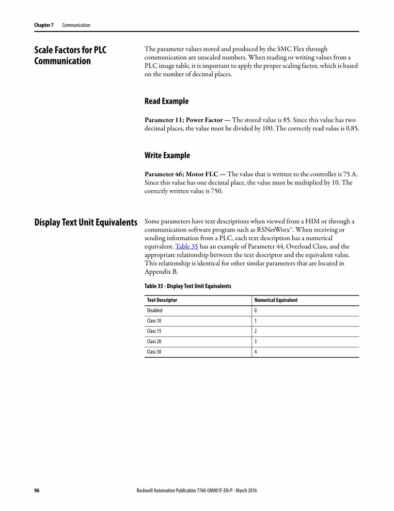
Chapter 7 Communication
Scale Factors for PLC Communication
The parameter values stored and produced by the SMC Flex through communication are unscaled numbers. When reading or writing values from a PLC image table, it is important to apply the proper scaling factor, which is based on the number of decimal places.
Read Example
Parameter 11; Power Factor — The stored value is 85. Since this value has two decimal places, the value must be divided by 100. The correctly read value is 0.85.
Write Example
Parameter 46; Motor FLC — The value that is written to the controller is 75 A. Since this value has one decimal place, the value must be multiplied by 10. The correctly written value is 750.
Display Text Unit Equivalents Some parameters have text descriptions when viewed from a HIM or through a communication software program such as RSNetWorx™. When receiving or sending information from a PLC, each text description has a numerical equivalent. Table 35 has an example of Parameter 44, Overload Class, and the appropriate relationship between the text descriptor and the equivalent value. This relationship is identical for other similar parameters that are located in Appendix B.
Table 35 - Display Text Unit Equivalents
Text Descriptor Numerical Equivalent
Disabled 0
Class 10 1
Class 15 2
Class 20 3
Class 30 4
96 Rockwell Automation Publication 7760-UM001F-EN-P - March 2016

Communication Chapter 7
Configuring Datalinks Datalinks are supported in the SMC Flex. A Datalink is a mechanism that is used by most drives to transfer data to and from the controller without using an Explicit Message. The SMC Flex supports 16 bit Datalinks, therefore the device can be configured to return up to four additional pieces of information without the need for an explicit message.
Rules for Using Datalinks• Each set of Datalink parameters in an SMC Flex are used by only one
adapter. If multiple adapters are connected, they cannot use the same Datalink.
• Parameter settings in the SMC determine the data that is passed through the Datalink mechanism.
• When you use a Datalink to change a value, the value is not written to the Non-Volatile Storage (NVS). The value is stored in volatile memory and lost when the drive loses power.
Parameters 88…103 are used to configure the Datalinks. For additional information regarding Datalinks, refer to the user manual for the communication interface being used.
Node addressing of the DPI communication card can be programmed via software or a hand-held DPI HIM. The onboard HIM cannot be used to address the communication card.
Updating Firmware The latest version of firmware and instructions for the SMC Flex can be obtained from www.ab.com.
The MV SMC Flex must use firmware release 6.003 or later. This manual pertains to units with firmware release 6.003 or later.
Rockwell Automation Publication 7760-UM001F-EN-P - March 2016 97

Chapter 7 Communication
Notes:
98 Rockwell Automation Publication 7760-UM001F-EN-P - March 2016
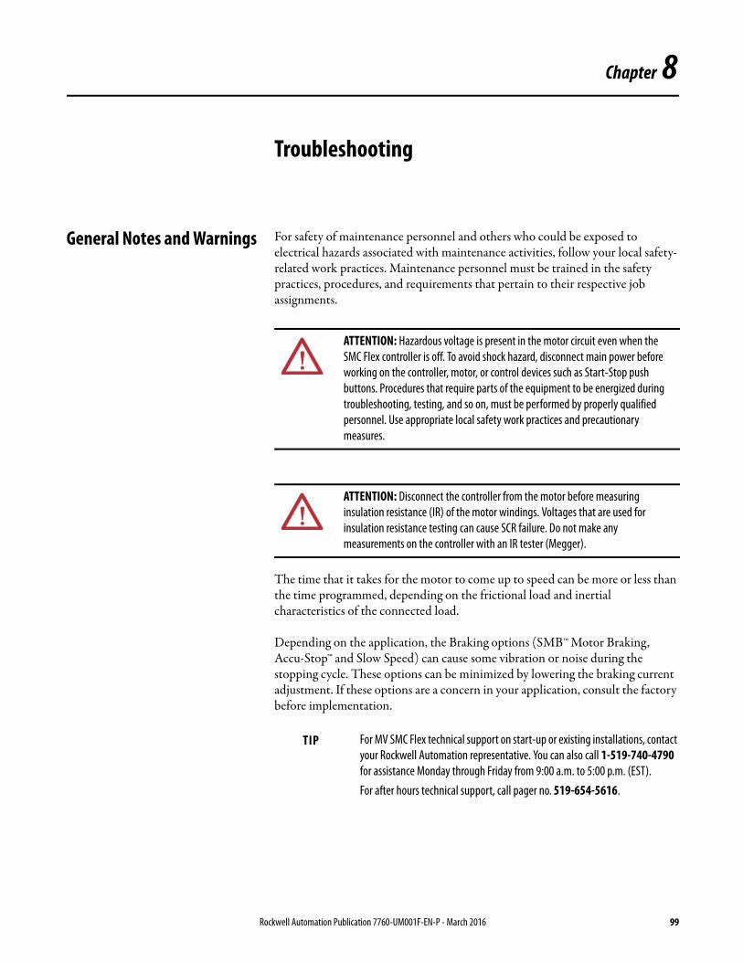
Chapter 8
Troubleshooting
General Notes and Warnings For safety of maintenance personnel and others who could be exposed to electrical hazards associated with maintenance activities, follow your local safety-related work practices. Maintenance personnel must be trained in the safety practices, procedures, and requirements that pertain to their respective job assignments.
The time that it takes for the motor to come up to speed can be more or less than the time programmed, depending on the frictional load and inertial characteristics of the connected load.
Depending on the application, the Braking options (SMB™ Motor Braking, Accu-Stop™ and Slow Speed) can cause some vibration or noise during the stopping cycle. These options can be minimized by lowering the braking current adjustment. If these options are a concern in your application, consult the factory before implementation.
ATTENTION: Hazardous voltage is present in the motor circuit even when the SMC Flex controller is off. To avoid shock hazard, disconnect main power before working on the controller, motor, or control devices such as Start-Stop push buttons. Procedures that require parts of the equipment to be energized during troubleshooting, testing, and so on, must be performed by properly qualified personnel. Use appropriate local safety work practices and precautionary measures.
ATTENTION: Disconnect the controller from the motor before measuring insulation resistance (IR) of the motor windings. Voltages that are used for insulation resistance testing can cause SCR failure. Do not make any measurements on the controller with an IR tester (Megger).
TIP For MV SMC Flex technical support on start-up or existing installations, contact your Rockwell Automation representative. You can also call 1-519-740-4790 for assistance Monday through Friday from 9:00 a.m. to 5:00 p.m. (EST).For after hours technical support, call pager no. 519-654-5616.
Rockwell Automation Publication 7760-UM001F-EN-P - March 2016 99

Chapter 8 Troubleshooting
The following flowchart is provided to aid in quick troubleshooting.
Figure 40 - Troubleshooting Flowchart
Table 36 - Fault Display Explanation
IMPORTANT In the case of the 1503E, refer to applicable documentation from the OEM for troubleshooting or repair. This manual must be used with the OEM-supplied documentation. It is suitable for commissioning, programming, calibration, metering, serial communications, diagnostics, troubleshooting, and maintenance of a standard solid-state controller.
YESFault Displayed?
NO
Define Natureof Trouble
Motor will not start – no output voltage to
motor
Motor rotates but does not accelerated
to full speed
Motor stopswhile running
IrregularStarts
Miscellaneous situations
SeeTable 36
SeeTable 37
SeeTable 38
SeeTable 39
SeeTable 40
SeeTable 41
Display Fault Code Possible Causes Possible Solutions
Line Loss (with phase indication) 1, 2, and 3 • Missing supply phase• Motor that is not connected properly• Improper or missing current or voltage
feedback
• Check for open line (for example, blown line fuse)• Check for open load lead• Check current transformer connections and module programming• Check voltage sensing board connections and module programming• Check ribbon cable connections between Interface Board and Control
Module• Check voltage feedback circuits• Consult factory
Shorted SCR 4, 5, and 6 • Shorted Power Module • Check for shorted SCR, replace if necessary (See Power Circuit on page 109)
Open Gate (with phase indication) 7, 8, and 9 • Open gate circuitry• Loose gate lead
• Perform power supply tests (Chapter 3)• Check gate lead connections to the gate driver boards and fiber optics
100 Rockwell Automation Publication 7760-UM001F-EN-P - March 2016

Troubleshooting Chapter 8
PTC Power Pole 10 • Controller ventilation is blocked• Controller duty cycle exceeded• Fan failure• Ambient temperature limit exceeded• Failed thermistor• Failed control module• Failed gate driver board• Failed fiber-optic cable• Failed interface board
• Check for proper ventilation• Check application duty cycle• Replace fan• Wait for controller to cool or provide external cooling• Check connection or replace thermistor• Replace control module• Test or replace gate driver board• Test or replace cable• Test or replace interface board or fiber-optic board; check ribbon cables
Motor PTC 12 • Motor ventilation is blocked• Motor duty cycle exceeded• PTC open
• Check for proper ventilation• Check application duty cycle• Wait for motor to cool or provide external cooling• Check resistance of PTC
Open Bypass 13, 14, 15 • Control voltage is low• Inoperable bypass contactor or breaker
• Check control voltage power supply• Check control circuit operation • Check control plug on contactor or breaker• Check that Aux. 1 is set correctly. External bypass or up to speed as
required by the application. See Status Indication on page 38.
No load 16, 17, 18, 40 • Loss of load side power wiring• Loss of feedback
• Check all load side power connections and motor windings• Check voltage sensing module
Line Unbalance 19 • Supply unbalance is greater than the user-programmed value
• The delay time is too short for the application
• Unbalanced feedback
• Check power system and correct if necessary• Extend the delay time to match the application requirements• Check voltage sensing module
Overvoltage 20 • Supply voltage is greater than user-programmed value
• Check power system and correct if necessary• Correct the user-programmed value
Undervoltage 21 • Supply voltage is less than user-programmed value
• The delay time is too short for the application
• Check power system and correct if necessary• Correct the user-programmed value• Extend the delay time to match the application requirements.
Overload 22 • Motor overloaded• Overload parameters are not matched
to the motor
• Check motor overload condition• Check programmed values for overload class and motor FLC
Underload 23 • Broken motor shaft• Broken belts, tool bits, and so on.• Pump cavitation
• Repair or replace motor• Check machine• Check pump system
Jam 24 • Motor current has exceeded the user programmed jam level
• Correct source of jam• Check programmed time value
Stall 25 • Motor has not reached full speed by the end of the programmed ramp time (plus Stall delay time)
• Correct source of stall
Phase Reversal 26 • Incoming supply voltage is not in the expected ABC sequence
• Check power wiring• Disable protection if not needed
Comm Loss 27, 28, 29 • Communication disconnection at the serial port
• Check for a communication cable disconnection to the SMC Flex controller
Network 30, 31, 32 • DPI network loss • Reconnect for each DPI connected device
Ground Fault 33 • Ground fault current level has exceeded programmed values
• Check power system and motor; correct if necessary• Check programmed ground fault levels to match application
requirements
Excess Starts/Hr. 34 • Number of starts in a one-hour period has exceeded the value programmed
• Wait an appropriate amount of time to restart• Consult factory if more than two starts per hour are required
Power Loss (with phase indication)(1)
35, 36, 37 • Missing supply phase (as indicated)• Loss of feedback
• Check for open line (for example, blown line fuse)• Check CT connections, replace Interface board
HAL_ID 38 • Faulty interface • Check ribbon cable connections between interface board and control module
• Replace interface board
Display Fault Code Possible Causes Possible Solutions
Rockwell Automation Publication 7760-UM001F-EN-P - March 2016 101

Chapter 8 Troubleshooting
Table 37 - Motor Will Not Start – No Output Voltage to the Motor
Table 38 - Motor Rotates (but does not accelerate to full speed)
NVS Error 39 • Data entry error • Check user data and perform a User Store function• Replace control module
Line Loss 41, 42, 43 • Line Distortion• High impedance connection
• Check supply voltage for capability to start/stop motor• Check for loose connections on line side or motor side power wires
V24 Recovery 44 • Internal power supply problem • Cycle control power to reset the control module• If Fault persists, replace control module
V24 Loss 45 • Internal power supply problem • Cycle control power to reset the control module• If Fault persists, replace control module
V Control Loss 46 • Internal sense circuit problem • Cycle control power to reset the control module• If Fault persists, replace control module
Option Input 1 48 • External Fault • Check programming of Parameter 132• Check status of device that is connected to Input 1
Option Input 2 49 • External Fault • Check programming of Parameter 24• Check status of device that is connected to Input 2
System Faults 128…209 • Control module internal fault • Cycle control power to reset the control module• Review control module wiring. The ground terminal must be securely
reconnected to earth ground. The RC snubber must be connected to all inductive loads in the control circuit that are connected to the control module terminals.
• If fault persists, replace the control module
(1) Prestart fault indication
Display Fault Code Possible Causes Possible Solutions
Display Possible Causes Possible Solutions
Fault displayed • See fault description • See Table 36 addressing fault conditions
Display is blank • Control voltage is absent• Failed control module
• Check control wiring and correct if necessary• Cycle control power• Replace control module
Stopped 0.0 A • Pilot devices• SMC Enable input is open at terminal 13• Terminal 16 is open• Start-Stop control has not been enabled for the human
interface module• Control voltage• Failed control module
• Check wiring• Check wiring• Check wiring• Follow the instructions on page 90 to page 92 enable
control capability• Check control voltage• Replace control module
Starting • Two or three power phases are missing • Check power system• Check voltage sensing module and connections
Display Possible Causes Possible Solutions
Fault displayed • See fault description • See Table 36 addressing fault conditions
Starting • Mechanical problems• Inadequate Current Limit setting• Failed control module
• Check for binding or external loading and correct• Check motor• Adjust the Current Limit Level to a higher setting• Replace control module
102 Rockwell Automation Publication 7760-UM001F-EN-P - March 2016

Troubleshooting Chapter 8
Table 39 - Motor Stops While Running
Table 40 - Irregular Starts
Although the default settings accommodate most applications, these tuning parameters may require multiple adjustments to achieve optimal results. Motor loading and power system conditions affect parameters, so one setting may not be optimal for all conditions.
Table 41 - Miscellaneous Situations(1)
Display Possible Causes Possible Solutions
Fault displayed • See fault description • See Table 36 addressing fault conditions
Display is blank • Control voltage is absent• Failed control module
• Check control wiring and correct if necessary• Replace control module
Stopped 0.0 A • Pilot devices• Failed control module
• Check control wiring and correct if necessary• Replace control module
Starting • Two or three power phases are missing• Failed control module
• Check power system• Check voltage sensing module and connections• Replace control module
Symptom Possible Causes Possible Solutions
Bypass contactor closes before motor is up to speed • Ramp time too short• Motor characteristics cause Up-to-Speed sensing too
early
• Increase ramp time (parameter 18) • Adjust parameter 114 higher (no more than 5% at a
time)
Motor is up to speed but bypass contactor is delayed in closing or does not close at all
• Ramp time too long• Motor characteristics cause Up-to-Speed sensing too
late or not at all
• Decrease ramp time• Adjust parameter 114 lower (no more than 5% at a
time)
Rough start, erratic current, growling from the motor (may see Line Faults)
• Poor grounding of the power system or controller• Poor power quality, electrical noise, harmonics, VFD
line notching
• Resolve ground issues• Adjust parameter 117 higher. Typical settings are 35 or
40. Not recommended to exceed 75 or go below 25.
During a Pump Stop, the motor takes more than 5 seconds to begin to decelerate or takes longer than the programmed stop time
• Motor or pump characteristics do not match the default setting
• Adjust parameter 34 to between 20 and 30 (do not go above 40).
(1) Various faults can occur if Parameter #15 is set to "Delta". It must be set to "Line" for all MV applications.
Display Possible Causes Possible Solutions
Motor current and voltage fluctuates with steady load • Motor• Erratic Load
• Verity type of motor as a standard squirrel cage induction motor
• Check load conditions
Erratic operation • Loose connections • Shut off all power to controller and check for loose connections
Accelerates too fast • Starting time• Initial torque• Current limit setting• Kickstart
• Increase starting time• Lower initial torque setting• Decrease current limit setting• Lower kickstart time or turn off
Accelerates too slow • Starting time• Initial torque• Current limit setting• Kickstart
• Decrease starting time• Increase initial torque setting• Increase current limit setting• Increase kickstart time or turn off
Fan does not operate • Wiring• Failed fans
• Check wiring and correct if necessary• Replace fans
Motor stops too quickly with Soft Stop option • Time setting • Verify the programmed stopping time and correct if necessary
Rockwell Automation Publication 7760-UM001F-EN-P - March 2016 103

Chapter 8 Troubleshooting
For Pump Stop issues, see Pump Application Considerations on page 39.
Control Module Removal The control module is not intended for field repair. The entire module must be replaced in the event of failure. The following procedure must be followed before unplugging the control module.
1. Remove all power from the equipment.
2. Make sure that the wires are properly marked and that the program parameters are recorded.
3. Disconnect all control wires to the control module.
4. Loosen the four control module screws.
5. Carefully rotate the module to the left, and unplug the five ribbon cables from the interface board.
Motor stops too slowly with Soft Stop option • Stopping time setting• Misapplication
• Verify the programmed stopping time and correct if necessary
• The Soft Stop option is intended to extend the stopping time for loads that stop suddenly when power is removed from the motor.
Fluid surges with pumps still occur with the Soft Stop option
• Misapplication • Soft Stop ramps voltage down over a set period. In the case of pumps, the voltage can drop too rapidly to prevent surges. A closed loop system such as Pump Control is more appropriately suited.
Motor overheats • Overload• Blocked ventilation• Duty cycle
• Allow motor to cool and reduce load. • Remove blockage and ensure motor is being
adequately cooled. • Preset Slow Speed and Accu-Stop options: Extended
operation at slow speeds reduces motor cooling efficiency. Consult motor manufacturer for motor limitations.
• Smart Motor Braking option: Check duty cycle. Consult motor manufacturer for motor limitations.
Motor short circuit • Winding fault • Identify fault and correct• Check for shorted SCR; replace if necessary• Secure the power terminals
Motor coasts when option stop is programmed • Option not programmed• Current loop power supply not active• Incorrect control logic
• Verify the option parameter settings and correct if necessary
• Verify current loop power supply (see Resistance Checks and Power Supply Tests)
• Verify connections to module terminals 16 and 17 (see Functional Description on page 44)
Display Possible Causes Possible Solutions
SHOCK HAZARD: To avoid shock hazard, disconnect the main power before working on the controller, motor, or control devices. Verify that all circuits are voltage free using a hot stick or appropriate voltage measuring device. Failure to do so may result in burns, injury, or death.
ATTENTION: When removing the control module, make sure to hold the module in place as the screws are removed, to avoid strain on the ribbon cables.
104 Rockwell Automation Publication 7760-UM001F-EN-P - March 2016

Troubleshooting Chapter 8
To install control module, follow the reverse order for removal.
The MV SMC Flex must use firmware release 6.003 or later. This manual pertains to units with firmware released 6.003 or later.
Voltage Feedback Circuit Test The most straightforward means of checking the feedback circuits is to perform the "Voltage-Sensing Board Replacement on page 105". Another possible test involves measuring the feedback voltages at the interface board (see Figure 27). This test can only be done with line voltage applied. If the motor does not start, it may be necessary to modify the control circuit temporarily to close the line contactor without applying a start signal to the SMC Flex module. In this case, the three line voltages (Line A, Line B, Line C) measured with respect to ground must be approximately 1 volt rms. The level in each phase must be the same as the other phases, within +/- 1%.
If any voltage is outside this range, there may be a problem with the system voltage or with the voltage sensing board. The load side voltages (Load A, Load B, Load C) are low, since the SCRs are not turned on, and only a low leakage current flows to the motor.
If the motor starts and runs, the line and load voltages must be the same when the bypass contactor is closed.
Voltage-Sensing Board Replacement
1. Mark the position of the ribbon cable and wires.
2. Disconnect the high voltage wires from the end that connects to the bus bars, and release the wires from the plastic stand off clips.
3. Release the locking mechanism on each side of the ribbon cable connector. Pull the ribbon cable straight out to prevent bending the pins. Remove the green ground wires.
4. Remove the four fasteners that secure the assembly to the panel. Remove the assembly, including the high-voltage wires, from the equipment.
For a 12 kV Voltage Sensing Board (VSB)a. Place the assembly on a flat surface (table or bench) and disconnect the
wires from the six channels at the end of the VSB. Cut the cable ties and remove the wires from the assembly.
b. Install the wires on the new assembly in the same positions and secure them with cable ties at the ends of the wire guide channels.
SHOCK HAZARD: To prevent electrical shock, main power must be disconnected before working on the sensing board. Verify that all circuits are voltage free using a hot stick or appropriate high voltage-measuring device. Failure to do so can result in injury or death.
Rockwell Automation Publication 7760-UM001F-EN-P - March 2016 105

Chapter 8 Troubleshooting
Figure 41 - Sensing Board High Voltage Wire Connections
For a 14.4 kV Voltage Sensing Board (VSB)c. Place the assembly on a flat surface (table or bench).d. Remove the nylon screws that secure the insulation shrouds from the
ends of the VSB channels, and remove the shrouds.e. Disconnect the wires from the six channels at the end of the VSB. Cut
the cable ties and remove the wires from the assembly.f. Install the wires on the new assembly in the same positions and secure
them with cable ties at the ends of the wire guide channels.g. Re-install the insulation shrouds with nylon screws, torque to 0.3 N•m
(2.7 lb•in).
Figure 42 - 14.4 kV Sensing Board Insulation Shrouds
Mounting Hardware
Cable Ties
Mounting Hardware
Wire Guide Channels
High Voltage Wires
ATTENTION: The insulation shrouds are required to prevent insulation breakdowns due to surge voltages. Failure to replace all six covers with nylon hardware before energizing may result in personal injury, property damage or economic loss.
Insulation Shroud
VSB channel
Nylon Screw goes here
106 Rockwell Automation Publication 7760-UM001F-EN-P - March 2016

Troubleshooting Chapter 8
5. Replace with the new assembly securing with all four fasteners (Figure 43).a. Reconnect the high-voltage wire to the bus bars and plastic stand off
clips.
6. Plug in ribbon cable properly, so the locking mechanism is engaged. Reconnect both ground wires and shield connection for the ribbon cable.
7. For personnel and equipment safety, reconnect both grounding connections to the sensing board.
Figure 43 - Sensing Board with mounting hardware placement
ATTENTION: The high-voltage wires must not touch earthed metal or bare conductors.
Mounting Hardware
Cable Ties
Mounting Hardware
Wire Guide Channels
High Voltage Wires
Mounting Hardware Mounting Hardware
Rockwell Automation Publication 7760-UM001F-EN-P - March 2016 107

Chapter 8 Troubleshooting
Current Loop Power Supply The current loop gate driver (CLGD) boards that are mounted on each PowerBrick (see Figure 45) receive power from two sources:
1. The snubber circuit (while the SCR power modules are active).
2. The current loop power supply, which maintains a pre-charge level of power during periods when the SCR power modules, are inactive. This allows SCR gating while the snubber circuit is being charged.
Figure 44 - Current Loop Power Supply
The current loop power supply provides a current of 40…50 A AC to each SCR power module phase assembly. If this current is not detected and fed back to the interface boards, stop maneuvers do not function (an alarm is generated).
Circuit Board Replacement The replacement of printed circuit boards is straightforward, but there are a number of precautions that must be considered when handling the boards.
1. Remove all power from the equipment.
Current LoopTransformer
Current Transformer
Transformer Guard
Ground Wire
180Ω, .6 Watt Resistor
ATTENTION: Some circuit boards may contain CMOS components, which can be destroyed by static charges that are generated by friction of materials that are made with synthetic fibers. Use of damaged circuit boards may also damage related components. A grounding wrist strap is recommended for handling sensitive circuit boards.
ATTENTION: To avoid shock hazard, disconnect the main power before working on the controller, motor, or control devices. Verify that all circuits are voltage free using a hot stick or appropriate voltage measuring device. Failure to do so may result in burns, injury, or death.
108 Rockwell Automation Publication 7760-UM001F-EN-P - March 2016

Troubleshooting Chapter 8
2. Carefully detach all wires, cables and connectors. Note their location and orientation. For the interface board, remove the control module.
3. For boards mounted with hardware, remove the hardware. Do not drop anything onto other circuits. For boards with nylon stand-off posts, squeeze the section above the board and carefully pull the board up and off the post.
4. Lift out the circuit board, and check that the replacement board is the correct part number and revision before installation (see on page 143). Install the new board by replacing the hardware, or pressing down onto nylon stand offs. Connect all wires, cables, and connectors. All switch and/or jumper settings on the new board must identical to the settings on the old board, and correct for the application.
Power Circuit PowerBrick (SCR) Testing
If a power semiconductor is suspected of malfunctioning, it may be checked as follows:
1. Remove all power from the equipment.
2. Measure DC resistance as follows:
Complete power pole (from line side to load side)
12 kV (5 PowerBricks) 100…145 kΩ15 kV (6 PowerBricks) 125…175 kΩ
It may be necessary to isolate one side of the power pole by disconnecting one of the flex braid connections at the top of the power pole assembly. Parallel resistance paths may be created due to earthing connections, motor windings or other connected equipment.
Variations may also be noted based on the devices used in different ratings of PowerBricks. The key is to look for notable differences between individual PowerBricks or power poles.
ATTENTION: The fiber-optic cables can be damaged if struck or bent sharply. Some have a locking feature that requires pinching the tab on the connector and gently pulling straight out. The component on the printed circuit board must be held to prevent damage.
SHOCK HAZARD: To avoid shock hazard, ensure the main power has been disconnected before working on the controller, motor or control devices. Verify that all circuits are voltage free using a hot stick or appropriate voltage measuring device. Failure to do so may result in burns, injury or death.
Rockwell Automation Publication 7760-UM001F-EN-P - March 2016 109

Chapter 8 Troubleshooting
If the power pole resistance is a multiple of 25 k lower than specified above, there may be one or more shorted SCRs in the PowerBricks.
3. If a short circuit is suspected, the power pole cart must be removed from the equipment to facilitate further testing. Refer to cart removal instructions in the Installation Instructions Manual (publication 7760-IN001).
4. Remove the clear plastic guards from the front and rear of the power pole assembly by removing two screws from the top and bottom of each guard.
5. Measure DC resistances as follows for each PowerBrick: (Refer to Figure 45).
C1 to C2: 21…29 kGate to Cathode (G/C): 4…40
Figure 45 - PowerBrick Current Loop Gate Driver Board Connections
6. If the resistance values are out of range, the PowerBrick must be removed from the power pole cart assembly. Refer to PowerBrick removal procedure in the Installation Manual (publication 7760-IN001_-EN-P).
CTJ1
Therm
Rx1 Tx1
CTJ2
Rx2 Tx2
Connection to H3
Snubber CapacitorConnection
Connection to H2
Snubber ResistorConnection
Current LoopCT Connector
Test Power SupplyConnector Gate Logic Fibre Optic Receiver
Temperature Feedback Fibre Optic Transmitter
Thermistor Connector (J2)
Match Band Character
SCR Gate Lead Connectors (J5)
Overvoltage Sense Connection
110 Rockwell Automation Publication 7760-UM001F-EN-P - March 2016

Troubleshooting Chapter 8
7. Refer to Figure 46 (PowerBrick Component Locations - Top View). Once the PowerBrick has been removed, remove the "HS2" wire from the top of the center heatsink to isolate the SCRs from the snubber and sharing resistors. Unplug the SCR gate connectors from the gate driver boards. Measure the DC resistance between the center and either end heatsink. The value should be greater than 100 k. If so, and the gate-cathode resistance is between 4-40 , the SCRs do not need to be changed. If the resistance is very low (< 4 ), an SCR has failed and must be replaced. Note the Match Band character from the front of the PowerBrick, and refer to Appendix C for replacement parts.
Figure 46 - PowerBrick Component Locations — Top View
8. If the SCRs are healthy, measure the DC resistance from "S1" on the upper gate driver board to "CS" as shown in Figure 46 (same as above). The connection to "CS" is made at the hex socket head screw that protrudes through the round plastic feature at the top of the snubber capacitor. This resistance should be 60 ±6. If a capacitance meter is available, connect from "CS" to "S2" on the lower gate driver board. The snubber capacitor should be 0.68 ±.04μF. If a capacitance meter is not available, an ohmmeter may be used, and should ramp up to >2 MΩ over several seconds. This method does not ensure that the capacitor is healthy, but shows if it is shorted or open. If the snubber components are suspect, repair or replace the PowerBrick. Refer to Appendix C for replacements parts.
HS2 HS3
RR1
RS1
Gate Driver Board
RS2 RS3
HS2 HS3
CS RR2
Rockwell Automation Publication 7760-UM001F-EN-P - March 2016 111

Chapter 8 Troubleshooting
9. Measure DC resistance between "C1" and "C2" at the gate driver boards. The value should be 32.5 ±1.7 k. If this point is open, the sharing resistors are damaged, or wire connections are open. Repair or replace the PowerBrick (refer to Appendix C).
10. If the PowerBrick is replaced, ensure that all components are securely connected per Figure 47. Check DC resistance values per step 5 above.
11. Replace the PowerBrick in the power pole assembly.
Figure 47 - PowerBrick Component Wiring Diagram
Thermistor
SCR1SCR2
Sharing Resistors
Snubber
112 Rockwell Automation Publication 7760-UM001F-EN-P - March 2016

Troubleshooting Chapter 8
Voltage Sensing Board Testing
1. Check the resistance of the voltage sensing module (refer to Figure 48). Remove the ribbon connector from J1 by pressing down on the locking tabs then gently pulling the connector out. Measure the resistance between each tap and the ground connection, and compare to the values in Figure 48. If the equipment includes an earthing switch, the board will be effectively short-circuited to ground. In this case, remove the ground wires before taking measurements.
Figure 48 - Voltage Sensing Board
Measure across R2, R4, R6, R10, R12, R14, R18, R20 and R22 located at the bottom of each leg of the module. The resistance should be 11.3 kohm. (The two ground connections must be connected to ground, or to each other if the module has been removed.)
L1 T1 L2 T2 T3L3
To Interface Board Ground Connections
RatedVoltage
12 kV14.4 kV
Tap 1, 3, 5to GND117.1 MΩ22.2 MΩ
Tap 2, 4, 6to GND125 MΩ
33.8 MΩ
Rockwell Automation Publication 7760-UM001F-EN-P - March 2016 113

Chapter 8 Troubleshooting
If the values for each leg vary by more than 1%, the voltage sensing module may need to be replaced. See Renewal Parts listing in Appendix C, and refer to Voltage-Sensing Board Replacement on page 105.
The white high voltage wires must be connected to the correct tap on each leg of the voltage sensing module. Failure to do so may result in equipment damage. Special care must be taken when working with the white high voltage wire to ensure it is not damaged.
The ribbon cable must be connected to J1 on the voltage sensing board or the equipment will not function.
2. When repairs are complete, re-assemble all parts, check all fasteners, and verify all connections are correct and tight. Make sure all barriers and mechanical parts are in place and secured.
3. Repeat PowerBrick (SCR) Testing on page 109 and Resistance Checks and Power Supply Tests on page 53.
Power Resistor Replacement When replacing the ceramic wire-wound type resistors, use caution when handling the parts. The resistor element is under a thin coating on the ceramic tube, and it may be damaged if dropped, struck or scraped.
ATTENTION: Grounds must be reconnected on the voltage sensing boards. Failure to do so may result in injury, death or damage to equipment.
ATTENTION: Make sure ground wires from the Voltage Sensing Module are securely connected to the ground bar in the low voltage panel or ground bus. Failure to do so may result in severe injury or equipment damage.
114 Rockwell Automation Publication 7760-UM001F-EN-P - March 2016

Chapter 9
Maintenance
Safety and Preventative The maintenance technician must become familiar with the layout and be aware of the basic system parameters. Only qualified technicians are allowed to work with this equipment under competent supervision.
Keep the components as dust free as possible. A scheduled program of inspection reduces the possibility of problems.
Periodic Inspection For OEM-supplied components, refer to the OEM documentation for recommended periodic maintenance procedures.
Inspect industrial control equipment periodically. Base the inspection intervals on environmental and operating conditions, and adjusted as indicated by experience. Rockwell Automation suggests an initial inspection within 3 or 4 months after installation.
Contamination
If inspection reveals that dust, moisture or other contamination has reached the control equipment, the source must be eliminated. Contamination in the control equipment can indicate an incorrect or ineffective enclosure, unsealed enclosure openings (conduit or other), or incorrect operating procedures. Replace dirty, wet, or contaminated parts unless they can be cleaned effectively by vacuuming or wiping.
ATTENTION: Servicing energized industrial control equipment can be hazardous. Severe injury or death can result from electrical shock, burn, or unintended actuation of controlled equipment. Recommended practice is to disconnect and lockout control equipment from power sources, and allow any stored energy in capacitors to dissipate. If it is necessary to work in the vicinity of energized equipment, the safety-related work practices of NFPA 70E, Electrical Safety Requirements for Employee Workplaces, must be followed.
ATTENTION: Allen-Bradley magnetic starters, contactors, and relays are designed to operate without lubrication – do not lubricate these devices since oil or grease on the pole face (mating surfaces) of the operating magnet may cause the device to stick in the “ON” mode. Erratic operation can result with injury or death.
Rockwell Automation Publication 7760-UM001F-EN-P - March 2016 115

Chapter 9 Maintenance
Parts of other devices are factory lubricated – if lubrication during use or maintenance of these devices is needed, it is specified in their individual instructions. If in doubt, consult the nearest Rockwell Automation sales office for information.
Vacuum Bottles
The contacts in a vacuum bottle cannot be seen or examined directly. They rely on the high vacuum to operate properly and to interrupt current.
See the vacuum contactor or breaker user manual for service instructions.
Terminals
Loose connections can cause overheating that can lead to equipment malfunction or failure. Check the tightness of all terminals and bus bar connections and securely tighten any loose connections. Replace any parts or wiring that is damaged by overheating.
Coils
If a coil exhibits evidence of overheating (cracked, melted or burned insulation), it must be replaced. In that event, check for and correct overvoltage or undervoltage conditions, which can cause coil failure. Be sure to clean any residues of melted coil insulation from other parts of the device or replace such parts.
Solid-state Devices
Solid-state devices require little more than a periodic visual inspection. Inspect printed circuit boards to determine whether all cables are properly seated in their connectors. Board locking tabs must also be in place. Necessary replacements must be made only at the PC board or plug-in component level. Do not use solvents on printed circuit boards. Where blowers are used, air filters, if supplied, must be cleaned or changed periodically depending on the specific environmental conditions encountered. For additional information, see NEMA Standards Publication No. ICS 1.1 - 1987 entitled “Safety Guidelines for the Application, Installation and Maintenance of Solid State Control”.
ATTENTION: Use of other than factory-recommended test equipment for solid-state controls may result in damage to the control or test equipment, or unintended actuation of the controlled equipment.
116 Rockwell Automation Publication 7760-UM001F-EN-P - March 2016

Maintenance Chapter 9
Static-Sensitive Items
While performing maintenance on the controller, special precautions must be observed in handling or touching certain static-sensitive components in the cabinet. Most circuit cards and SCRs can be damaged by electro-static discharge (ESD). If you contact an ESD-sensitive component during maintenance, they must be grounded. Ground with a wriststrap that is connected to an approved ground.
Overload Maintenance After a Fault Condition
See NEMA Standards Publication No. ICS 2 Appendix A entitled “Maintenance of Motor controllers after a fault condition”.
Final Check Out
After maintenance or repair of industrial controls, always test the control system for proper functioning under controlled conditions that avoid hazards in the event of a control malfunction.
Keep Good Maintenance Records
Good maintenance records help reduce shutdowns by demanding the use of proper test equipment, and an appropriate inventory of spare parts. This suggestion is most helpful in locating possible intermittent problems by pointing to a particular area of recurring trouble within the overall system. For additional information see NFPA 70B, “RECOMMENDED PRACTICE FOR ELECTRICAL EQUIPMENT MAINTENANCE”, published by the National Fire Protection Association.
Power Components
Keep power components clean and free of dirt and obstructions. This practice avoids tracking and heat build-up, increasing the life of the device.
Rockwell Automation Publication 7760-UM001F-EN-P - March 2016 117

Chapter 9 Maintenance
Control Components – Electronic
Keep printed circuit boards clean and free of any accumulations of dirt and foreign materials.
Materials that create static electricity should never be allowed near circuit boards while in the unit, or in storage. Caution should be used when one is near or handling circuit boards. There are no other requirements, other than housekeeping standards, that the maintenance program requires on the logic control components.
Fans
Physically rotating and observing the fans for noise or binding will indicate if fan failure is evident.
Interlocks
Verify that interlocks function as intended, and have not been forced, damaged, or removed.
Barriers
Verify that all barriers are in place and securely fastened.
Environmental Considerations
Hazardous materials
Environmental protection is a top priority for Rockwell Automation. The facility that manufactured this medium voltage product operates an environmental management system that is certified to the requirements of ISO 14001. As part of this system, this product was reviewed in detail throughout the development process to ensure that environmentally inert materials were used wherever feasible. A final review has found this product to be substantially free of hazardous material.
Rockwell Automation is actively seeking alternatives to potentially hazardous materials for which no feasible alternatives exist. In the interim, the following precautionary information is provided for your protection and for the protection of the environment. Contact the factory for any environmental information on any material in the product or with questions regarding environmental impact.
118 Rockwell Automation Publication 7760-UM001F-EN-P - March 2016

Maintenance Chapter 9
Capacitor Dielectric Fluid
The fluids that are used in the snubber capacitors are considered safe and are fully sealed within the capacitor housings. Shipping and handling of this fluid is typically not restricted by environmental regulations. In the unlikely event that capacitor fluid leaks out, avoid ingestion or contact with skin or eyes. Rubber gloves are recommended for handling.
To clean up fluid, soak into an absorbent material and discard into an emergency container. Do not dispose into any drain or into general landfill refuse. Dispose according to local regulations. The same precautions exist if disposing of an entire capacitor.
Printed Circuit Boards
Printed circuit boards can contain a small amount of lead in components and materials. Shipping and handling these boards are typically not restricted by environmental regulations, however, lead is considered a hazardous substance. Circuit boards must be disposed of according to local regulations and must not be disposed of with general landfill refuse.
In Case Of Fire
This product is protected against arcing faults and therefore it is unlikely it would cause of a fire. The materials that are used are self-extinguishing (that is, they do not burn without a sustained external flame). If the product is subjected to a sustained fire from some other source, some of the polymer materials produce toxic gases. Wear a self-contained breathing apparatus to protect against inhalation of toxic gases.
Disposal
When disposing of the product, disassemble and separate into groups of recyclable material as much as possible (steel, copper, plastic, wire, and so forth). Send these materials to local recycling facilities. In addition, all disposal precautions that are mentioned here must also be taken for those particular materials.
Rockwell Automation Publication 7760-UM001F-EN-P - March 2016 119

Chapter 9 Maintenance
Notes:
120 Rockwell Automation Publication 7760-UM001F-EN-P - March 2016
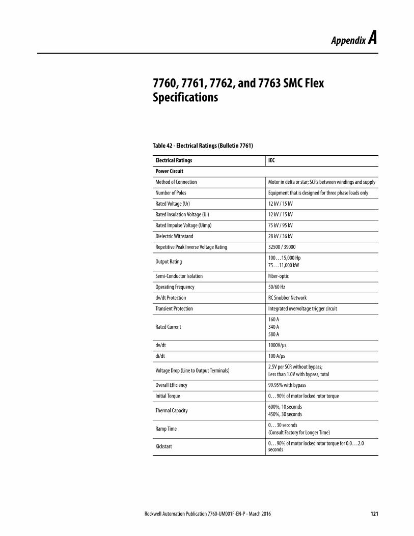
Appendix A
7760, 7761, 7762, and 7763 SMC Flex Specifications
Table 42 - Electrical Ratings (Bulletin 7761)
Electrical Ratings IEC
Power Circuit
Method of Connection Motor in delta or star; SCRs between windings and supply
Number of Poles Equipment that is designed for three phase loads only
Rated Voltage (Ur) 12 kV / 15 kV
Rated Insulation Voltage (Ui) 12 kV / 15 kV
Rated Impulse Voltage (Uimp) 75 kV / 95 kV
Dielectric Withstand 28 kV / 36 kV
Repetitive Peak Inverse Voltage Rating 32500 / 39000
Output Rating100…15,000 Hp75…11,000 kW
Semi-Conductor Isolation Fiber-optic
Operating Frequency 50/60 Hz
dv/dt Protection RC Snubber Network
Transient Protection Integrated overvoltage trigger circuit
Rated Current160 A340 A580 A
dv/dt 1000V/μs
di/dt 100 A/μs
Voltage Drop (Line to Output Terminals)2.5V per SCR without bypass;Less than 1.0V with bypass, total
Overall Efficiency 99.95% with bypass
Initial Torque 0…90% of motor locked rotor torque
Thermal Capacity600%, 10 seconds450%, 30 seconds
Ramp Time0…30 seconds(Consult Factory for Longer Time)
Kickstart 0…90% of motor locked rotor torque for 0.0…2.0 seconds
Rockwell Automation Publication 7760-UM001F-EN-P - March 2016 121
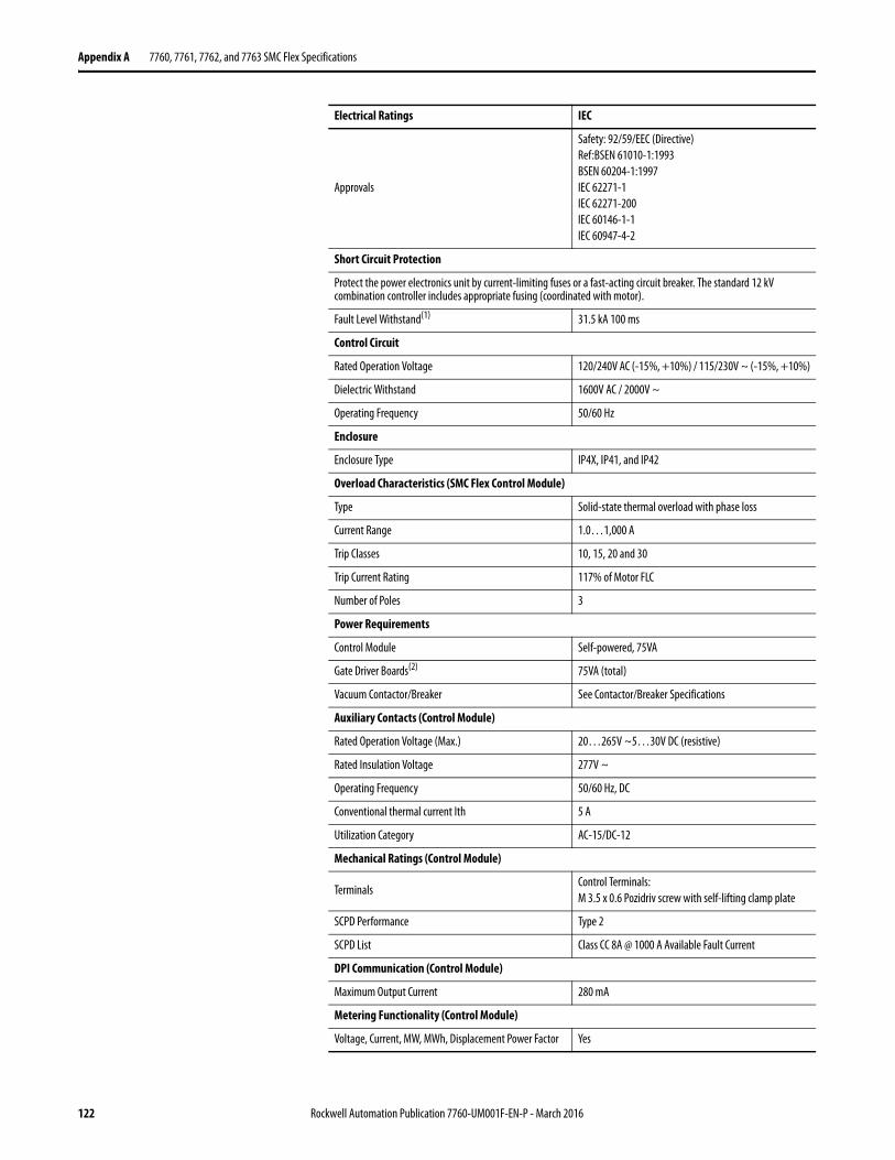
Appendix A 7760, 7761, 7762, and 7763 SMC Flex Specifications
Approvals
Safety: 92/59/EEC (Directive)Ref:BSEN 61010-1:1993BSEN 60204-1:1997IEC 62271-1IEC 62271-200IEC 60146-1-1IEC 60947-4-2
Short Circuit Protection
Protect the power electronics unit by current-limiting fuses or a fast-acting circuit breaker. The standard 12 kV combination controller includes appropriate fusing (coordinated with motor).
Fault Level Withstand(1) 31.5 kA 100 ms
Control Circuit
Rated Operation Voltage 120/240V AC (-15%, +10%) / 115/230V ~ (-15%, +10%)
Dielectric Withstand 1600V AC / 2000V ~
Operating Frequency 50/60 Hz
Enclosure
Enclosure Type IP4X, IP41, and IP42
Overload Characteristics (SMC Flex Control Module)
Type Solid-state thermal overload with phase loss
Current Range 1.0…1,000 A
Trip Classes 10, 15, 20 and 30
Trip Current Rating 117% of Motor FLC
Number of Poles 3
Power Requirements
Control Module Self-powered, 75VA
Gate Driver Boards(2) 75VA (total)
Vacuum Contactor/Breaker See Contactor/Breaker Specifications
Auxiliary Contacts (Control Module)
Rated Operation Voltage (Max.) 20…265V ~5…30V DC (resistive)
Rated Insulation Voltage 277V ~
Operating Frequency 50/60 Hz, DC
Conventional thermal current Ith 5 A
Utilization Category AC-15/DC-12
Mechanical Ratings (Control Module)
TerminalsControl Terminals:M 3.5 x 0.6 Pozidriv screw with self-lifting clamp plate
SCPD Performance Type 2
SCPD List Class CC 8A @ 1000 A Available Fault Current
DPI Communication (Control Module)
Maximum Output Current 280 mA
Metering Functionality (Control Module)
Voltage, Current, MW, MWh, Displacement Power Factor Yes
Electrical Ratings IEC
122 Rockwell Automation Publication 7760-UM001F-EN-P - March 2016

7760, 7761, 7762, and 7763 SMC Flex Specifications Appendix A
Table 43 - Environmental Ratings
Table 44 - Controller Deratings
Tachometer Input (Control Module)
Voltage 0…5V DC; 4.5V DC=100% speed
Current 1.0 mA
(1) Excludes power electronics
(2) For stop maneuvers, the gate driver boards are pre-charged with a current loop power supply (75 VA).
Environmental Ratings IEC
Operating Temperature Range 0…50°C (32…122°F) (with derating above 40°C/104°F)
Storage and Transportation Temperature Range -20…75°C (-4…167°F)
Altitude 0…1000 meters (3300 feet) without derating
Humidity 5…95% (noncondensing)
Pollution Degree 2
Altitude Range
Power Cell RatingReduce B.I.L. and power frequency Withstand Rating By:(2)
(2) Altitude correction factors for insulation withstand voltages that are derived from IEC 62271-1.
160 A 340 A 580 A
Reduce Max. Continuous Current Rating By:(1)
(1) Current deratings that are shown are the minimum levels. Additional derating may be required due to power fuse limitations. Consult factory for additional details.
1000…2000 m(3300…6600 ft.)
5 A 10A 15 A 13%
2001…3000 m(6601…9900 ft.)
10 A 20 A 30 A 28%
3001…4000 m(9901…13,200 ft.)
15 A 30 A 45 A 44%
4001…5000 m(13,201…16,500 ft.)
20 A 40 A 60 A 63%
Table 45 - Power Cell Current Rating at Ambient Temperature
40 °C (104 °F) 50 °C (122 °F)
160 A 130 A
340 A 270 A
580 A 460 A
Electrical Ratings IEC
Rockwell Automation Publication 7760-UM001F-EN-P - March 2016 123

Appendix A 7760, 7761, 7762, and 7763 SMC Flex Specifications
Table 46 - Power Bus Specifications
Attribute Value
Main Power Bus
Bus Bar Material Tin-plated insulated copper
Optional Power Bus Plating Silver
Continuous Current Rating at 40 °C (104 °F)
1250, 2000 A
Maximum Full Load Temperature Rise 65 °C (149 °F)
Maximum Full Load Temperature 105 °C (221 °F) @ 40 °C ambient
Fault Withstand Current Rating (3 seconds)
31.5 kA RMS SYM
Type of Bus Bracing Epoxy cast, glass polyester
Dimensions per Phase 1250 A2000 A
Qty 1 – 10 x 80 mm (3/8 x 3 in.)Qty 2 – 10 x 80 mm (3/8 x 3 in.)
Cross Sectional Area per Phase 1250 A2000 A
800 mm² (1.125 in.²) total1600 mm² (2.25 in.²) total
Insulating Material Between Phases and Ground
Type: Sleeve, heat shrink
Material: Polyolefin
Thickness: 3.0 mm (0.12 in. / 120 mils)
Anti-hygroscopic: 0.25%
Electrical Strength: 500V/mil (20 kV/mm)
Unit Bus
Bus Bar Material Bare copper
Optional Unit Bus Plating Tin or Silver
Continuous Current Rating at 40 °C (104 °F)
630 A
Fault Withstand Current Rating 31.5 kA, 100 msec
Insulation Material (where required)
Type: Sleeve, heat shrink
Material: Polyolefin
Thickness: 3.0 mm (0.12 in. / 120 mils)
Anti-hygroscopic: 0.25%
Electrical Strength: 500V/mil (20 kV/mm)
Ground Bus
Ground Bus Material Bare copper
Optional Ground Bus Material Tin-plated copper
Continuous Current Rating at 40 °C (104 °F)
600 A
Dimensions 600 A 8 x 50 mm (5/16 x 2 in.)
Cross Sectional Area 600 A 400 mm² (0.625 in.²) total
Fault Withstand Current Rating (3 seconds)
31.5 kA
124 Rockwell Automation Publication 7760-UM001F-EN-P - March 2016

7760, 7761, 7762, and 7763 SMC Flex Specifications Appendix A
Table 47 - Medium Voltage Spring Actuated Vacuum Circuit Breaker: 10…12 kV
Attribute Value
Voltage Ratings(1)
(1) The voltage and current ratings that are listed are valid up to 1000 m (3300 ft). See Controller Derating chart for ratings above this altitude.
Maximum Rated Voltage 12 kV
Basic Impulse Level (B.I.L.) Withstand– Phase to Ground, Phase to Phase (kV)
75
Rated Insulation Voltage 12 kV
Withstand Voltage at 50 Hz 28 kV
Frequency Ratings 50 / 60 Hz
Current Ratings(1)
Rated Normal current (40 °C/104 °F) 630 A
Rated Breaking Capacity (kA) (rated short-circuit breaking current symmetrical)
16, 20, 25, 31.5
Rated short-time withstand current (3s) (kA) 16, 20, 25, 31.5
Making Capacity (kA) 40, 50, 63, 80
Pole Distance (mm) 150
Opening Time (ms) 33…60
Arcing Time (ms) 10…15
Total Breaking Time (ms) 43…75
Closing Time (ms) 60…80
Operating Temperature (°C/°F) -5…50 °C/23…122 °F (with derating)
Rockwell Automation Publication 7760-UM001F-EN-P - March 2016 125

Appendix A 7760, 7761, 7762, and 7763 SMC Flex Specifications
Table 48 - Medium Voltage Spring Actuated Vacuum Circuit Breaker: 12.5…15 kV
Attribute Value
Voltage Ratings(1)
(1) The voltage and current ratings that are listed are valid up to 1000 m (3300 ft). See Controller Derating chart for ratings above this altitude.
Maximum Rated Voltage 17.5 kV
Basic Impulse Level (B.I.L.) Withstand– Phase to Ground, Phase to Phase (kV)
95
Rated Insulation Voltage 17.5 kV
Withstand Voltage at 50 Hz 38 kV
Frequency Ratings 50 / 60 Hz
Current Ratings(1)
Rated Normal current (40 °C) 630 A
Rated Breaking Capacity (kA) (rated short-circuit breaking current symmetrical)
16, 20, 25, 31.5
Rated short-time withstand current (3s) (kA) 16, 20, 25, 31.5
Making Capacity (kA) 40, 50, 63, 80
Pole Distance (mm) 150
Opening Time (ms) 33…60
Arcing Time (ms) 10…15
Total Breaking Time (ms) 43…75
Closing Time (ms) 60…80
Operating Temperature (°C/°F) -5…50 °C/23…122 °F (with derating)
126 Rockwell Automation Publication 7760-UM001F-EN-P - March 2016

7760, 7761, 7762, and 7763 SMC Flex Specifications Appendix A
Table 49 - Medium Voltage Magnetically Actuated Vacuum Circuit Breaker: 10…12 kV
Attribute Value
Voltage Ratings(1)
(1) The voltage and current ratings listed are valid up to 1000 m (3300 feet). Please refer to Controller Derating chart for ratings above this altitude.
Maximum Rated Voltage 12 kV
Basic Impulse Level (B.I.L.) Withstand– Phase to Ground, Phase to Phase (kV)
75
Rated Insulation Voltage 12 kV
Withstand Voltage at 50 Hz 28 kV
Frequency Ratings 50 / 60 Hz
Current Ratings(1)
Rated Normal current (40 °C) 630 A
Rated Breaking Capacity (kA) (rated short-circuit breaking current symmetrical)
16, 20, 25, 31.5
Rated short-time withstand current (3s) (kA) 16, 20, 25, 31.5
Making Capacity (kA) 40, 50, 63, 80
Pole Distance (mm) 150
Opening Time (ms) 35…45
Arcing Time (ms) 10…15
Total Breaking Time (ms) 45…60
Closing Time (ms) 50…60
Operating Temperature (°C/°F) -25…50 °C/-13…122 °F (with derating)
Rockwell Automation Publication 7760-UM001F-EN-P - March 2016 127

Appendix A 7760, 7761, 7762, and 7763 SMC Flex Specifications
Table 50 - Medium Voltage Magnetically Actuated Vacuum Circuit Breaker: 12.5…15 kV
Attribute Value
Voltage Ratings(1)
(1) The voltage and current ratings listed are valid up to 1000 m (3300 feet). Please refer to Controller Derating chart for ratings above this altitude.
Maximum Rated Voltage 17.5 kV
Basic Impulse Level (B.I.L.) Withstand– Phase to Ground, Phase to Phase (kV)
95
Rated Insulation Voltage 17.5 kV
Withstand Voltage at 50 Hz 38 kV
Frequency Ratings 50 / 60 Hz
Current Ratings(1)
Rated Normal current (40 °C) 630 A
Rated Breaking Capacity (kA) (rated short-circuit breaking current symmetrical)
16, 20, 25, 31.5
Rated short-time withstand current (3 s) (kA) 16, 20, 25, 31.5
Making Capacity (kA) 40, 50, 63, 80
Pole Distance (mm) 150
Opening Time (ms) 35…45
Arcing Time (ms) 10…15
Total Breaking Time (ms) 45…60
Closing Time (ms) 50…60
Operating Temperature (°C/°F) -25…50 °C/-13…122 °F (with derating)
128 Rockwell Automation Publication 7760-UM001F-EN-P - March 2016

7760, 7761, 7762, and 7763 SMC Flex Specifications Appendix A
Table 51 - Medium Voltage Vacuum Contactor: 10 to 12 kV
Attribute Value
Voltage Ratings(1)
(1) The voltage and current ratings listed are valid up to 1000 m (3300 feet). See Controller Derating chart for ratings above this altitude.
Maximum Rated Voltage 12 kV
Rated insulation voltage 12 kV
Impulse withstand voltage 75 kV
Withstand Voltage at 50 Hz 28 kV
Frequency Ratings 50 / 60 Hz
Current Ratings(1)
Rated service current A 400
Rated normal current A 400
Short-time withstand current for 1 s A 6000
Rated Peak Current kA 15
Rated short-circuit time S 1
Maximum rated admissible overcurrent for ½ period (peak value)
kA 55
Rated load and overload characteristics in category of use:
Category AC4) 100 closing operations (A) 4000
Category AC4) 25 opening operations (A) 4000
Electrical Life at rated current verified as in Category AC1
Operations 1,000,000
Mechanical Life Operations 1,000,000
Short-circuit breaking capacity (O…3min-CO…3min-CO)
(A) 4000
Short-circuit making capacity (O…3min-CO-3min…CO)
(A) Peak 8000
Switching TimesOpening Time (lower and upper limit) (ms) 20…30
Closing Time (lower and upper limit) (ms) 30…50
Relative Humidity, without condensation
% <95
Operating Temperature °C/°F --5…50 °C/23…122 °F (with derating)
Rockwell Automation Publication 7760-UM001F-EN-P - March 2016 129

Appendix A 7760, 7761, 7762, and 7763 SMC Flex Specifications
Notes:
130 Rockwell Automation Publication 7760-UM001F-EN-P - March 2016

Appendix B
Parameter Information
Table 52 - Parameter List
Group Parameter Name
Parameter Number
Units Min./ Max. Default Settings Parameter Description User Settings
Metering Volts Phase A-B 1 VProvides the phase-to-phase supply voltage measurements at all times, including bypass operation.
Metering Volts Phase B-C 2 V Provides the phase-to-phase supply voltage measurements at all times, including bypass operation.
Metering Volts Phase C-A 3 V Provides the phase-to-phase supply voltage measurements at all times, including bypass operation.
Metering Current Phase A 4 A Provides the phase A motor current measurement.
Metering Current Phase B 5 A Provides the phase B motor current measurement.
Metering Current Phase C 6 A Provides the phase C motor current measurement.
Metering Watt Meter 7 KW/MW Provides the power usage of the connected motor. This value is calculated from the voltage, current and power factor measurements.
Metering Kilowatt Hours 8 KWH/MWH
Provides the power usage over time of the connected motor.
Metering Elapsed Time 9 Hours Indicates the total time of motor operation in hours. The accumulated time is updated continuously during run time.
Metering Meter Reset 10 NO ETM Reset KWH Reset NO
Provides the user the capability to reset the value stored in the elapsed time (9) and kilowatt hours (8) meters to zero.
Metering Power Factor 11 0.00…0.99 Provides the operational displacement power factor measurement of the connected motor.
Metering Mtr Therm Usage 12 %MTU 0…100
Provides the theoretical model of motor heating as a percentage value. At 100% MTU, the controller will fault on overload. This model is based on the motor thermal overload calculation.
Metering Motor Speed 13 % 0…100 Indicates the operating percentage of motor base speed when linear ramp is selected and an external tachometer is used.
Basic Set Up SMC Option 14 Standard Brake Pump Control
This a “read-only” parameter that identifies to the user the type of control module installed.
Basic Set Up Motor Connection 15 Line/Delta Line
This parameter allows the user the ability to select the power wiring configuration of the SMC to the attached motor (WYE or DELTA). A fault controlled means of disconnecting the line should always be use in the DELTA mode.
Do not set to “Delta”
Rockwell Automation Publication 7760-UM001F-EN-P - March 2016 131

Appendix B Parameter Information
Basic Set Up Line Voltage 16 V 0…15,000 480
This parameter sets the base voltage for the under / over voltage protective features. For medium voltage applications the controller has internal capabilities set of multipliers that correspond to the line voltage dividers.
Basic Set Up Starting Mode 17
Full VoltageCurrent LimitSoft Start LinearSpeed PumpStart
Soft Start Allows the user to select the type of start provided with controller configuration.
Basic Set Up Ramp Time 18 Secs 0…30 10
Allows the user to program the time (0…30 s) that the controller performs the starting maneuver. The starting maneuver will automatically transition to bypass and full voltage if the controller senses that the motor has reached full speed prior to the ramp time completion. Also refer to Parameter 129.
Basic Set Up Initial Torque 19 %LRT 0…90 70
When using the soft start mode, this parameter allows the user to adjust the initial torque level applied to the motor at the beginning of the start maneuver.
Basic Set Up Cur Limit Start Level 20 %FLC 50…600 350
When using the current limit starting mode, this parameter allows the user to adjust the current level applied to the motor during the start maneuver.
Basic Set Up Reserved 21 Reserved
Basic Set Up Kickstart Time 22 Secs 0.0…2.0 0.0
When programmed with a non-zero value, this parameter provides a torque pulse for the programmed time period at the beginning of the starting maneuver (0.0…2.0 s).
Basic Set Up Kickstart Level 23 %LRT 0…90 0
When the Kickstart Time is programmed, this parameter provides the user with the ability to set the level of the torque pulse applied to the motor (approx. 0…90%).
Basic Set Up Option Input 2 24
Disable PresetSlow SpeedDual RampFault Fault NCNetwork ClearFault
Disable Provides the user with the ability to define the function of option Input #2 (disable, coast, stop option, fault, fault N.C., network).
Dual Ramp Starting Mode 2 25
Full VoltageCurrent LimitSoft Start LinearSpeed PumpStart
Soft Start When the dual ramp mode is selected, this parameter allows the user to select the type of ramp mode used for the second ramp profile.
Dual Ramp Ramp Time 2 26 Secs 0…30 10
When the dual ramp mode is selected, this parameter allows the user to program the time (0…30 s) that the controller performs the starting maneuver for profile #2. Also refer to Parameter 130.
Dual Ramp Initial Torque 2 27 %LRT 0…90 70
When using the soft start mode for profile #2, this parameter allows the user to adjust the initial torque level applied to the motor at the beginning of the start maneuver.
Dual Ramp Cur Limit Level 2 28 %FLC 50…600 350
When using the current limit starting mode for profile #2, this parameter allows the user to adjust the current level applied to the motor during the start maneuver.
Group Parameter Name
Parameter Number
Units Min./ Max. Default Settings Parameter Description User Settings
132 Rockwell Automation Publication 7760-UM001F-EN-P - March 2016
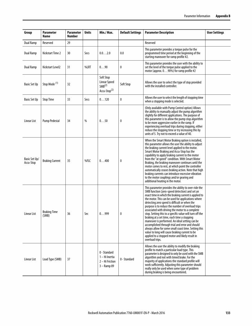
Parameter Information Appendix B
Dual Ramp Reserved 29 Reserved
Dual Ramp Kickstart Time 2 30 Secs 0.0…2.0 0.0 This parameter provides a torque pulse for the programmed time period at the beginning of the starting maneuver for ramp profile #2.
Dual Ramp Kickstart Level2 31 %LRT 0…90 0 This parameter provides the user with the ability to set the level of the torque pulse applied to the motor (approx. 0…90%) for ramp profile #2
Basic Set Up Stop Mode (1) 32
Soft StopLinear SpeedSMB(2)
Accu-Stop(2)
Soft Stop Allows the user to select the type of stop provided with the installed controller.
Basic Set Up Stop Time 33 Secs 0…120 0 Allows the user to select the length of stopping time when a stopping mode is selected.
Linear List Pump Pedestal 34 % 0…50 0
(Only available with Pump Control option) Allows the ability to manually adjust the pump algorithm slightly for different applications. The purpose of this parameter is to allow the pump stop algorithm to be more aggressive earlier in the ramp. If experiencing overload trips during stopping, either reduce the stopping time or try increasing this by units of 5. Try not to exceed a value of 40.
Basic Set Up/Accu-Stop Braking Current 35 %FLC 0…400 0
When the Smart Motor Braking option is installed, this parameter allows the user the ability to adjust the braking current level applied to the motor. Smart Motor Braking and Accu-Stop has the capability to apply braking current to the motor from the “at speed” condition. With Smart Motor Braking, the braking maneuver continues until the motor comes to rest, at which point the controller automatically ceases braking action. Note that high braking currents can introduce excessive vibration to the motor couplings and/or gearing and additional heating in the motor.
Linear List Braking Time (SMB) 36 Sec 0…999 0
This parameter provides the ability to over-ride the SMB function (zero-speed detection) and set an exact time in which the braking current is applied to the motor. This can be used for applications where detecting zero speed is difficult or when the purpose is to reduce the number of overload trips associated with driving the motor to a complete stop. Setting this to a specific value will turn off the braking at a set time, each time a stopping maneuver is performed. An ideal setting can be accomplished through trial and error and should always allow for some small coast time. Setting this value to long will cause braking current to be applied to a stopped motor and likely result in overload trips.
Linear List Load Type (SMB) 37
0 - Standard1 – Hi Inertia2 – Hi Friction3 – Ramp 89
0 - Standard
Allows the user the ability to modify the braking profile to match a particular load type. This parameter is designed to only be used with the SMB algorithm and not with timed brake. For the majority of applications the standard profile will work sufficiently. Adjusting this parameter should really only be used when some type of problem during braking is being encountered.
Group Parameter Name
Parameter Number
Units Min./ Max. Default Settings Parameter Description User Settings
Rockwell Automation Publication 7760-UM001F-EN-P - March 2016 133

Appendix B Parameter Information
Linear List High Eff Brake (SMB) 38
% of Stopping Time
0…99 0
This parameter is used to extend the SMB braking time by a percentage of the typical stopping time. The need to adjust this parameter can occur when braking is applied to high efficiency motors and relates to the counter EMF produced by these motors. This setting should never really exceed 50%. Nuisance overload faults will likely occur if set incorrectly.
Preset SS/Accu-Stop Slow
Speed Sel 39 SS Low SS High SS High
When this option is used, this parameter provides the user the ability to select between the “Low” and “High” settings for both the Preset Slow Speed and Accu-Stop control options.
Preset SS/Accu-Stop Slow Speed Dir 40 SS FWD SS REV SS FWD
Provides the user the ability to program the motor’s direction of rotation. Note that with the Preset Slow Speed option, the controller has the capability to operate the motor in the reverse direction during slow speed operation without the use of a reversing contactor.
Preset SS/Accu-Stop Slow Accel Cur 41 %FLC 0…450 0
Provides the user the ability to program the current to slow speed operation for both the Preset Slow Speed and Accu-Stop control options. This setting is typically load dependent.
Preset SS/Accu-Stop Slow Running Cur 42 % FLC 0…450 0
Provides the user the ability to program the operating current of slow speed operation for both the Preset Slow Speed and Accu-Stop control options. This setting is typically load dependent.
Accu-Stop Stopping Current 43 %FLC 0…400 0
Provides adjustment capability for the braking intensity from slow speed operation to the “stopped” condition for the Accu-Stop control option.
Basic Set Up/Overload Overload Class 44
DisableClass 10Class 15Class 20Class 30
Class 10
Allows the user to select the time-to-trip for the built-in overload. This selection is based on the type of motor being used and the application it is being applied to.
Basic Set Up/Overload Service Factor 45 0.01…1.99 1.15 This motor nameplate value is used to determine
the ultimate overload trip current.
Basic Set Up/Overload Motor FLC 46 A 1.0…2200.0 1.0
Sets the base current for use with all the current based protection features (jam, over / under load, motor overload). The motor nameplate FLA is to be used.
Basic Set Up/Overload Overload Reset 47 Manual Auto Manual Allows the user to select between an auto and
manual reset mode for all Overload faults.
Linear List OL Shunt Time 48 Sec 0…999 0
This parameter prevents the overload from accumulating or incrementing the Motor Thermal Usage (%MTU) during the programmed “shunt” time. This function is allowable under some electrical codes for loads which have long acceleration times (i.e. High inertia). As a general rule of thumb, this time should never exceed the programmed start time. Setting this parameter longer than necessary can result in motor overheating that is not being accounted for in the thermal model.
Linear List OL Trip Enable/Disable 49
0= Disable1= Enable
Enable
This parameter disables the overload from tripping during slow speed, pump stopping, and braking maneuvers. Motor Thermal Usage (%MTU) continues to increment during these maneuvers. Setting this parameter to disable can result in motor overheating or potential damage.
Group Parameter Name
Parameter Number
Units Min./ Max. Default Settings Parameter Description User Settings
134 Rockwell Automation Publication 7760-UM001F-EN-P - March 2016

Parameter Information Appendix B
Overload Overload A Lvl 50 %MTU 0…100 0 Allows the user to set an overload level (% of motor thermal usage) that will cause an alarm when the level exceeds the setting.
Underload Underload F Lvl 51 %FLC 0…99 0 Allows the user to set a current (% of line FLC) that will cause a fault when the motor current falls below this value. A zero value is the “off” setting.
Underload Underload F Dly 52 Secs 0…99 0
Allows the user the ability to prevent some nuisance faults by entering a delay period that provides a window that the motor current condition must persist within for the controller to fault.
Underload Underload A Lvl 53 %FLC 0…99 0 Allows the user to set a current (% of line FLC) that will cause an Alarm when the motor current falls below this value. A zero value is the “off” setting.
Underload Underload A Dly 54 Secs 0…99 0
Allows the user the ability to prevent some nuisance Alarm conditions by entering a delay period that provides a window that the motor current condition must persist within for the controller to Alarm.
Under-voltage Undervolt F Lvl 55 %V 0…99 0
Allows the user to set a voltage (% of line Voltage) that will cause a fault when the voltage falls below this value. A zero value is the “off” setting.
>80 recommended
Under-voltage Undervolt F Dly 56 Secs 0…99 0
Allows the user the ability to prevent some nuisance faults by entering a delay period that provides a window that the voltage condition must persist within for the controller to fault.
1 sec recommended
Under-voltage Undervolt A Lvl 57 %V 0…99 0
Allows the user to set a voltage (% of line Voltage) that will cause an Alarm when the voltage falls below this value. A zero value is the “off” setting.
Under-voltage Undervolt A Dly 58 Secs 0…99 0
Allows the user the ability to prevent some nuisance Alarms by entering a delay period that provides a window that the voltage condition must persist within for the controller to Alarm.
Over-voltage Overvolt F Lvl 59 %V 0…199 0 Allows the user to set a voltage (% of line Voltage) that will cause a fault when the voltage falls above this value. A zero value is the “off” setting.
Over-voltage Overvolt F Dly 60 Secs 0…99 0
Allows the user the ability to prevent some nuisance faults by entering a delay period that provides a window that the voltage condition must persist within for the controller to fault.
Over-voltage Overvolt A Lvl 61 %V 0…199 0 Allows the user to set a voltage (% of line Voltage) that will cause an Alarm when the voltage falls above this value. A zero value is the “off” setting.
Over-voltage Overvolt A Dly 62 Secs 0…99 0
Allows the user the ability to prevent some nuisance Alarms by entering a delay period that provides a window that the voltage condition must persist within for the controller to Alarm.
Unbalance Unbalance F Lvl 63 %V 0…25 0
Allows the user to set a percentage of line to line Voltages that will cause a fault when the voltage falls above this value. A zero value is the “off” setting.
Unbalance Unbalance F Dly 64 Secs 0…99 0
Allows the user the ability to prevent some nuisance faults by entering a delay period that provides a window that the voltage unbalance condition must persist within for the controller to fault.
Unbalance Unbalance A Lvl 65 %V 0…25 0
Allows the user to set a percentage of line to line Voltages that will cause an Alarm when the voltage falls above this value. A zero value is the “off” setting.
Group Parameter Name
Parameter Number
Units Min./ Max. Default Settings Parameter Description User Settings
Rockwell Automation Publication 7760-UM001F-EN-P - March 2016 135

Appendix B Parameter Information
Unbalance Unbalance A Dly 66 Secs 0…99 0
Allows the user the ability to prevent some nuisance Alarms by entering a delay period that provides a window that the voltage unbalance condition must persist within for the controller to Alarm.
Jam Jam F Lvl 67 %FLC 0…1000 0 Allows the user to set an instantaneous over current level (% of line FLC) that will cause a fault. A zero value is the “off” setting.
Jam Jam F Dly 68 Secs 0…99 0
Allows the user the ability to prevent some nuisance faults by entering a delay period that provides a window that the motor over current condition must persist within for the controller to fault.
Jam Jam A Lvl 69 %FLC 0…1000 0 Allows the user to set an instantaneous over current level (% of line FLC) that will cause an Alarm. A zero value is the “off” setting.
Jam Jam A Dly 70 Secs 0…99 0
Allows the user the ability to prevent some nuisance Alarms by entering a delay period that provides a window that the motor over current condition must persist within for the controller to Alarm.
Stall Stall Delay 71 Secs 0.0…10.0 0
This feature allows the user to program the amount of time beyond the initial start maneuver for the motor to be at speed. A setting of zero means that the stall detection feature is disabled.
1 sec recommended
Ground Fault Gnd Flt Enable 72 DisableEnable
Disable Enables ground fault protection when used with an external core balanced ground fault sensor.
Ground Fault Gnd Flt Level 73 A 1.0…5.0 2.5Allows the user to set a current (core balance current) that will cause a fault when the current is above this value.
Ground Fault Gnd Flt Delay 74 Secs 0.1…250.0 0.5
Allows the user the ability to prevent some nuisance faults by entering a delay period that provides a window that the ground fault condition must persist within for the controller to fault.
Ground Fault Gnd Flt Inh Time 75 Secs 0…250 10 Allow the user the ability to disable/inhibit ground fault protection for a selected time when starting.
Ground Fault Gnd Flt A Enable 76 DisableEnable
Disable Enables a ground fault protection Alarm when used with an external core balanced ground fault sensor.
Ground Fault Gnd Flt A Lvl 77 A 1.0…5.0 2.0 Allows the user to set a current (core balance current) that will cause an Alarm when the current is above this value.
Ground Fault Gnd Flt A Dly 78 Secs 0…250 10
Allows the user the ability to prevent some nuisance Alarms by entering a delay period that provides a window that the ground fault condition must persist within for the controller to Alarm.
PTC PTC Enable 79 DisableEnable
Disable Enables PTC based over-temperature protection when used with external PTC sensors.
Phase Reversal Phase Reversal 80
DisableEnable
Disable
Allows the user to prevent starting if the incoming line phase sequence is not correct. The incoming power lines are expected to be in an ABC sequence. The controller will fault if power lines are out of the ABC sequence.
Restart Starts Per Hour 81 0…99 0Limits the number of starts that can occur in a one-hour period. This feature includes a “sliding window” for the one-hour time period.
2 recomMended
Restart Restart Attempts 82 0…5 0
Allows the user to enable the SMC-Flex to auto-restart for up-to 5 attempts, other than an SCR overtemp or motor overload fault. The start signal must remain active for a restart to occur.
Group Parameter Name
Parameter Number
Units Min./ Max. Default Settings Parameter Description User Settings
136 Rockwell Automation Publication 7760-UM001F-EN-P - March 2016

Parameter Information Appendix B
Restart Restart Delay 83 Secs 0…60 0 Provides a delay time between restart attempts to allow for the condition to be removed.
Linear List Line Fault Disable 84
0=Disable1=Disable F12=DisableF413=Enable
Enable
This parameter gives the user the ability to selectively disable specific fault codes such as F1, F2, F3 and F41, F42, F43. These faults are used to detect problems with incoming power and the detection of appropriate zero crosses (F1) or the firing of the SCRs based on the current and voltage characteristics associated with the SCR turning off (F41). These faults can only occur during starting or stopping and are usually related to the incoming power condition.
Linear List Emergency Run 850 = Disable1=Enable
Disable
This parameter defeats all running faults and is only effective in the “run” mode. It will not override faults prior to starting (i.e. shorted SCR). This parameter is reset to “off/disable” when control power is recycled.
Linear List Current Loss 860 = Disable1=Enable
Enable This parameter allows the user to override a current loss fault. This is indicative of the typical failure mode of a damaged CT.
Comm Masks Logic Mask 87 8-bit binary 0
Allows the user to enable or disable control from various serial interface ports (DPI) with a “0” setting. If a port is set to “1”, the port will be allowed to control the SMC and will produce a comm. fault if disconnected.
DataLinks Data In A1 88 0 16 bit Datalink
DataLinks Data In A2 89 0 16 bit Datalink
DataLinks Data In B1 90 0 16 bit Datalink
DataLinks Data In B2 91 0 16 bit Datalink
DataLinks Data In C1 92 0 16 bit Datalink
DataLinks Data In C2 93 0 16 bit Datalink
DataLinks Data In D1 94 0 16 bit Datalink
DataLinks Data In D2 95 0 16 bit Datalink
DataLinks Data Out A1 96 0 16 bit Datalink
DataLinks Data Out A2 97 0 16 bit Datalink
DataLinks Data Out B1 98 0 16 bit Datalink
DataLinks Data Out B2 99 0 16 bit Datalink
DataLinks Data Out C1 100 0 16 bit Datalink
DataLinks Data Out C2 101 0 16 bit Datalink
DataLinks Data Out D1 102 0 16 bit Datalink
DataLinks Data Out D2 103 0 16 bit Datalink
Motor Data Motor ID 104 0…65535 0
Allows the user the ability to assign a specific identification number to a motor and controller combination. This can be useful for network applications where you may need to locate a specific motor/controller based on a network address.
Motor Data CT Ratio 105 1…1500 Sets the proper current ratio when an external current transformer is used for Medium Voltage applications. (example, for 150:5, set 150)
Motor Data MV Ratio 106 1…10000 Sets the proper feedback scaling when used for Medium Voltage applications. See Table 6
Group Parameter Name
Parameter Number
Units Min./ Max. Default Settings Parameter Description User Settings
Rockwell Automation Publication 7760-UM001F-EN-P - March 2016 137

Appendix B Parameter Information
Basic Set Up Aux1 Config 107
NormalNormal NCUp To SpeedUp To SpeedNC Fault FaultNC AlarmAlarm NCNetworkNetwork NCExternal Bypass
Normal
Allows the user the ability to configure each Auxiliary relay contact for a specific operation
Normal = SMC in RUN
External Bypass or Up-to-Speed (see Chap. 1)
Basic Set Up Aux3 Config 108
NormalNormal NCUp To SpeedUp To SpeedNC Fault FaultNC AlarmAlarm NCNetworkNetwork NCExternal Bypass
Alarm
Allows the user the ability to configure each Auxiliary relay contact for a specific operation
Normal = SMC in RUN
Basic Set Up Aux4 Config 109
NormalNormal NCUp To SpeedUp To SpeedNC Fault FaultNC AlarmAlarm NCNetworkNetwork NCExternal Bypass
Normal
Allows the user the ability to configure each Auxiliary relay contact for a specific operation
Normal = SMC in RUN
Basic Set Up Aux2 Config 110
NormalNormal NCUp To SpeedUp To SpeedNC Fault FaultNC Alarm AlarmNC NetworkNetwork NCExternal Bypass
Fault
Allows the user the ability to configure each Auxiliary relay contact for a specific operation
Normal = SMC in RUN
Language Language 111
EnglishFrenchSpanishGermanPortugueseMandarin
English Allows the user to change the text display to one of the available options.
Linear List Timed Start 1120 = Disable1=Enable
Disable
This parameter can be used to force the starting profile to complete its entire time period and ignore an early up-to-speed detection. The default is set to “Disabled”, so that the SMC can determine when the motor is at speed.
See parameter 114 before adjusting this parameter.
Group Parameter Name
Parameter Number
Units Min./ Max. Default Settings Parameter Description User Settings
138 Rockwell Automation Publication 7760-UM001F-EN-P - March 2016

Parameter Information Appendix B
Linear List I Shut Off 113 % current 0…37 0
This parameter adjusts the level of current at which the SMC determines that the SCR has turned off. Since this parameter has the potential to modify the SCR control scheme, it is important that adjustments be made with the help of Technical Support.
Do not change without factory assistance.
Linear List UTS Level 114 % up to speed 0…100 75
The SMC has the ability to automatically determine if the motor is up to speed. If there is a problem with detecting the up-to-speed condition, this parameter can be modified to compensate. Rule of thumb is this number should be increased on high efficiency motors experiencing problems. If the SMC is detecting the up-to-speed condition too late (or not at all) this number should be decreased on very low efficiency motors. Be careful when adjusting this level. Improper adjustment can cause the SMC to start at full voltage.
All Parameter Mgmt 115 Ready Load Default Ready Allows the user to load factory default values for all
parameters.
Basic Set Up Backspin Timer 116 Secs 0…999 0 (Only available with the Pump Control option) Ensures that a specific amount of time passes between a stop and start sequence.
Linear List V Shut Off Level 117 % V 0…100 25
This parameter provides the user with the ability to manually adjust the level for the controller’s voltage shut off detection. Since this parameter has the potential to modify the SCR control scheme, it is important that adjustments be made with the help of Technical Support. It is important that you do not disable both parameter 113 and this one at the same time, otherwise SCR firing instability can occur.
Linear List OL Reset Level 118 % 0…99 75
Sets the level at which the motor overload is allowed to be reset. Once the TCU% has dropped below the program level, the device can be reset manually or will auto reset if programmed for auto-reset operation.
Linear List Ambient Temperature 119 0…60 50
Provides the ability to compensate for a lower or higher ambient temperature condition. The ambient temperature programmed should be representative of the actual nominal temperature (or worst case condition) since improper programming can result in nuisance tripping or SCR damage due to true SCR overheating.
Not applicable to MV applications
Linear List Notch Position 120 % 40.0…100.0 87.5
This parameter allows for the starting control algorithm to be manually modified. It is recommended that you do not make changes to this parameter without specifically talking with Technical Support.
Do not change
Linear List Notch Maximum (pump control) 121 50…70 70
This parameter allows for the pump stopping control algorithm to be manually modified. It is recommended that you do not make changes to this parameter without specifically talking with Technical Support.
Do not change
Linear List Start Delay 122 Sec 0…30 0 An internal on-delay timer. Ensures that a subsequent start can not be initiated for a preset amount of time.
Group Parameter Name
Parameter Number
Units Min./ Max. Default Settings Parameter Description User Settings
Rockwell Automation Publication 7760-UM001F-EN-P - March 2016 139

Appendix B Parameter Information
Linear List By-pass Delay 123 Sec 0…15 0
For applications that routinely see fast spikes of current or overload conditions (more than 125% of the SMC’s frame rating) this parameter can be used to reduce the cycling between SCR and by-pass. This time delay parameter will allow the SMC to stay under SCR control for the duration of time programmed.
Not applicable to MV applications
Linear List Fault 1 124 0…255 Fault buffer #1 allows display of the current fault. A value of 0 indicates that there is no current fault.
Linear List Fault 2 125 0…255 Fault buffer #2 represents fault history of the device with fault #1 being the current fault and fault #5 being the oldest fault kept in memory.
Linear List Fault 3 126 0…255 Fault buffer #3 represents fault history of the device with fault #1 being the current fault and fault #5 being the oldest fault kept in memory.
Linear List Fault 4 127 0…255 Fault buffer #4 represents fault history of the device with fault #1 being the current fault and fault #5 being the oldest fault kept in memory.
Linear List Fault 5 128 0…255 Fault buffer #5 represents fault history of the device with fault #1 being the current fault and fault #5 being the oldest fault kept in memory.
Linear List Ramp Time E 129 Sec 0…999 0
This parameter provides the user with the ability to extend the ramp time beyond the initial range of 0-30 seconds. To use this parameter, parameter 18 must be set to 0.
Linear List Ramp Time 2E 130 Sec 0…999 0Allows for the second ramp time to also be extended. To use this parameter, parameter 26 must be set to 0.
Linear List Stop Time E 131 Sec 0…999 0Allows the stop time be extended beyond the limit of 120 seconds. Parameter 33 must be set to 0 for this parameter to be active.
Basic Set Up Option Input 1 132
DisableCoast StopOption FaultFault NCNetwork
Stop Option Provides the user with the ability to define the function of option Input #1.
Basic Set Up Stop Input 133 Coast Stop Option Coast Provides the user with the ability to define the
function of the stop input.
Linear List Elapsed Time 2 134 Hours 0.0/3000.0 This is an additional Elapsed Time Meter that cannot be reset by the user. It increments exactly as the Elapsed Time but cannot be reset.
(1) Pump option modules default to “Pump Stop”.
(2) Brake option modules only.
Group Parameter Name
Parameter Number
Units Min./ Max. Default Settings Parameter Description User Settings
140 Rockwell Automation Publication 7760-UM001F-EN-P - March 2016

Appendix C
Spare Parts
Table 53 - PowerBrick™ Replacements
Part Number Description PowerBrick Current Rating
Match Designator
81020-230-51-R Complete PowerBrick (excluding gate driver board)
160 A
W
81020-752-51-R IJ
81020-761-51-R Complete Rollout Assembly 10…12 kV (with power bricks, gate driver boards, and CT loop) W
81020-295-51-R Complete Rollout Assembly 12.4…14.4 kV (with PowerBricks, gate driver boards, and CT loop) W
81020-230-57-R Complete PowerBrick replacement assembly(excluding gate driver board)
340 A
Y
81020-230-58-R Z
81020-761-57-R Complete Rollout Assembly 10…12 kV (with power bricks, gate driver boards, and CT loop) Y
81020-295-57-R Complete Rollout Assembly 12.4…14.4 kV (with power bricks, gate driver boards, and CT loop) Y
81020-752-85-R Complete PowerBrick replacement assembly(excluding gate driver board)
580 A
DM
81020-752-86-R DN
81020-761-85-R Complete Rollout Assembly 10…12 kV (with power bricks, gate driver boards, and CT loop) DM
81020-295-85-R Complete Rollout Assembly 12.4…14.4 kV (with power bricks, gate driver boards, and CT loop) DM
Rockwell Automation Publication 7760-UM001F-EN-P - March 2016 141

Appendix C Spare Parts
Table 54 - Common Parts
Table 55 - Accessories
7703E – For OEM products, refer to OEM-supplied documentation for specific spare parts list.
Part Number Description Quantity
80190-520-02-R Current loop self-powered gate driver board (CLGD) 1 per SCR
81020-237-52-RVoltage Sensing Board (VSB)
10…12 kV1 per controller
81020-237-53-R 12.1…15 kV
80190-440-03-R Interface Board 1 per controller
80190-680-01-R Fiber Optic Board 1 per controller
80026-762-51-R Fiber Optic Cable Kit 1 per power pole
81023-213-09-R Fiber Optic Cable Kit (Low Voltage Panel) 1 per controller
80187-051-51-RTest Power Supply
120V AC for North America 1 per controller
80187-245-51-R Universal
80022-133-02-R Current loop power transformer 100VA, 115/230:1.5V 1 per controller
80018-246-57-R Current loop cable 9.6 m (15 ft) 1 per power pole
81023-036-61-R Current loop mounting bracket assembly (includes hardware) 1 per power brick + 6
81023-213-01-R Current loop flange 1 per SCR + 6
81023-095-51-R Current loop current transformer 1 per SCR
80022-163-01-R Current loop sense CT 1 per controller
80026-146-56-R Ribbon cable from VSB to interface board 1 per controller
80174-201-01-R Ribbon cable from control module to Interface board
6-pin 2 per controller
80174-201-02-R 8-pin 3 per controller
Part Number Description Quantity
41391-454-01-S1FX Control Module (Standard)1
41391-454-01-B1FX Control Module (Pump Control)
80026-427-01-R Frequency to voltage converter to Tachometer feedback(1)
(1) Optional equipment.
2…10 kHz1
80026-427-02-R 0…100 kHz
80026-433-01-R Power Supply for frequency to voltage converter 1
142 Rockwell Automation Publication 7760-UM001F-EN-P - March 2016
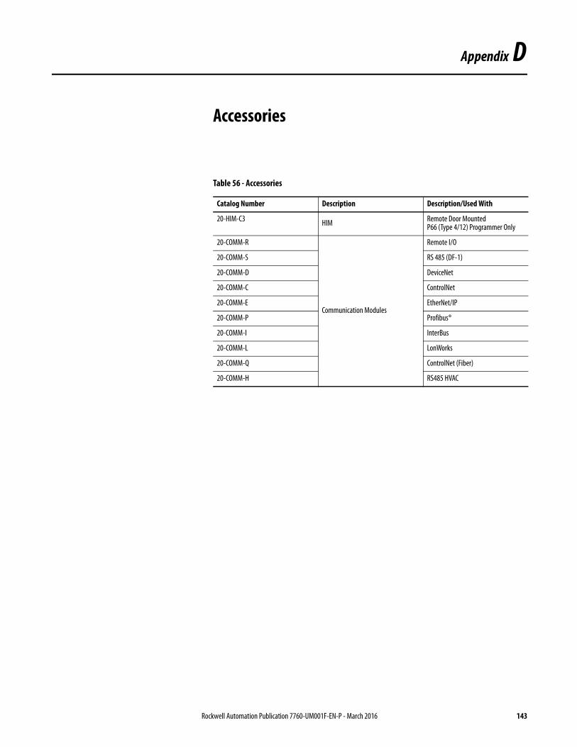
Appendix D
Accessories
Table 56 - Accessories
Catalog Number Description Description/Used With
20-HIM-C3 HIM Remote Door Mounted P66 (Type 4/12) Programmer Only
20-COMM-R
Communication Modules
Remote I/O
20-COMM-S RS 485 (DF-1)
20-COMM-D DeviceNet
20-COMM-C ControlNet
20-COMM-E EtherNet/IP
20-COMM-P Profibus®
20-COMM-I InterBus
20-COMM-L LonWorks
20-COMM-Q ControlNet (Fiber)
20-COMM-H RS485 HVAC
Rockwell Automation Publication 7760-UM001F-EN-P - March 2016 143

Appendix D Accessories
Notes:
144 Rockwell Automation Publication 7760-UM001F-EN-P - March 2016

Index
Numerics7703 – OEM Controller
description 137760 – Retrofit Controller
description 147761– Combination Controller
description 157762 – Combination Controller (Vacuum
Contactor)description 16
7763 – Combination Controller (Vacuum Breaker)
description 17
BBarriers
Maintenance 118Basic Set-Up
Programming 71
CCircuit Board Replacement 108Coils
Maintenance 116Commisioning Procedure
Preliminary Set-Up 47Commissioning Checks 49Commissioning Procedure
Start-Up 59Communications
overview 37, 87Control Components – Electronic
Maintenance 118Control Function Tests 58Control Module
Removal 104Control Module Removal 104Control Options
Braking Controloverview 40
overview 39Pump Application Considerations 39Pump Control
overview 39Control Wiring
Options 82controllers
7703 – OEM 137760 – Retrofit 147761 – Combination 157762 – Combination 167763 – Combination 17
Current Limit StartProgramming 68
Current Limit Start starting modeoverview 23
Current Loop Gate Driver (CLGD) Boardoverview 41
Current Loop Power Supply 108
DDiagnostics
Clear Fault (clearing a fault) 84Fault Buffer 84
codes 84Fault Definitions 85Fault Display 83overview 83
Dual Ramp StartProgramming 69
Dual Ramp Start starting modeoverview 24parameters 24
EExcessive Starts/Hour
Protection and Diagnosticsoverview 35
FFans
Maintenance 118Fault Buffer 84
codes 84Fault Definitions 85Fault Display 83
clearing 84Explanation 100
Full Voltage StartProgramming 70
Full Voltage Start starting modeoverview 24
Functional Descriptionoverview 44
GGround Fault
Alarm 33Protection and Diagnostics
overview 32Trip 32
Ground Fault Alarm 33Ground Fault Trip 32
HHardware
Current Loop Gate Driver (CLGD) Boardoverview 41
description 40Interface Board
Rockwell Automation Publication 7760-UM001F-EN-P - March 2016 145

Index
overview 41Power Module
description 41Hi-Pot and Megger Test 50Human Interface Module (HIM)
overview 79
II/O
overview 36Interface Board
overview 41Interlocks
Maintenance 118
JJam Detection
Protection and Diagnosticsoverview 31
KKeypad, Programming
description 61
LLine Faults
Protection and Diagnosticsoverview 35
Linear SpeedProgramming 70
Linear Speed Acceleration and Deceleration starting mode
overview 26
MMaintenance
Barriers 118Coils 116Contamination 115Control Components – Electronic 118Environmental Considerations 118
Disposal 119Hazardous materials 118
Fans 118Interlocks 118Periodic Inspection 115Power Components 117Safety and Preventative 115Solid-State Devices 116Static-Sensitive Items 117Terminals 116Vacuum Bottles 116
Meteringoverview 36, 77viewing data 77
modulesSMC Flex Control 21
Motor ProtectionProgramming 73
MV SMC Flex ModuleProgramming 50
OOpen Gate
Protection and Diagnosticsoverview 34
OptionsControl Wiring 82overview 79Programming Parameters 81
OverloadProtection and Diagnostics
overview 28Overtemperature
Protection and Diagnosticsoverview 35
overviewCommunications 37, 87Control Options 39
Braking Control 40Pump Control 39
Diagnostics 83Functional Description 44Hardware
Current Loop Gate Driver (CLGD) Board 41
Interface Board 41Power Module 41
Human Interface Module (HIM) 79I/O 36Metering 36, 77Options 79Programming 37, 61Protection and Diagnostics
Excessive Starts/Hour 35Ground Fault 32Jam Detection 31Line Faults 35Open Gate 34Overload 28Overtemperature 35Overvoltage 30PTC Protection 33Stall Protection 31Thermistor 33Unbalance 31Underload 30Undervoltage 30
Starting Modes 22Current Limit 23Dual Ramp 24Full Voltage 24Linear Speed Acceleration and Decelera-
tion 26Preset Slow Speed 25Selectable Kickstart 23Soft Start 22
146 Rockwell Automation Publication 7760-UM001F-EN-P - March 2016

Index
Soft Stop 27Status Indication 38Voltage Sensing Module 58
OvervoltageProtection and Diagnostics
overview 30
Pparameters, programming 64
management 66Electrically Erasable Programmable
Read-only Memory (EEPROM) 67Random Access Memory (RAM) 66Read-Only Memory (ROM) 66
modification 67Password, Programming 65
modification procedure 65Power Components
Maintenance 117Power Factor Correction Capacitors 18
Implementation 20Typical Bulletin 7760 Line Diagram 18Typical Bulletin 7762 Line Diagram 19Typical Bulletin 7763 Line Diagram 19
Power Moduleoverview 41
Power Resistor Replacement 114PowerBrick
Accessories 142Common Parts 142Replacement Parts 141
Preset Slow SpeedProgramming 71
Preset Slow Speed starting modeoverview 25
ProgrammingBasic Set-up 71Current Limit Start 68Dual Ramp Start 69Example Settings
Jam 74Overvoltage 74Underload 74Undervoltage 74
Full Voltage Start 70Keypad
description 61Linear Speed 70Menu 61
structure hierarchy 62Motor Data Entry 75Motor Information 75Motor Protection 73MV SMC Flex Module 50overview 37, 61parameter list 64parameter management 66
Electrically Erasable Programmable Read-only Memory (EEPROM) 67
Random Access Memory (RAM) 66Read-Only Memory (ROM) 66
Parameter Menu
structure hierarchy 63parameter modification 67Parameters
Options 81Password 65
modification procedure 65Preset Slow Speed 71Soft Start 68Stop Control 70
Protection and Diagnostics 28Excessive Starts/Hour
overview 35Ground Fault
overview 32Jam Detection
overview 31Line Faults
overview 35Open Gate
overview 34Overload
overview 28Overtemperature
overview 35Overvoltage
overview 30PTC Protection
overview 33Stall Protection
overview 31Thermistor
overview 33Unbalance
overview 31Underload
overview 30Undervoltage
overview 30PTC Protection
Protection and Diagnosticsoverview 33
Trip 34PTC Trip 34Pump Application 39
RResistance Checks and Power Supply Tests 53
SSelectable Kickstart starting mode
overview 23SMC Flex Control Module
description 21SMC Flex Module Parameters 131
List 131SMC Flex Specifications
Controller Deratings 123Electrical Ratings (Bullet 7761) 121Environmental Ratings 123Medium Voltage Magnetically Actuated
Vacuum Circuit Breaker10 to 12 kV 127
Rockwell Automation Publication 7760-UM001F-EN-P - March 2016 147
Index
12.5 to 15 kV 128Medium Voltage Spring Actuated Vacuum
Circuit Breaker10 to 12 kV 12512.5 to 15 kV 126
Medium Voltage Vacuum Contactor10 to 12 kV 129
Power Bus Specifications 124Soft Start
Programming 68Soft Start starting mode
overview 22Soft Stop starting mode
overview 27Solid-State Devices
Maintenance 116Spare Parts
PowerBrickAccessories 142Common Parts 142Replacements 141
Stall ProtectionProtection and Diagnostics
overview 31Starting Modes
Current Limit Startoverview 23
Dual Ramp Startoverview 24parameters 24
Full Voltage Startoverview 24
Linear Speed Acceleration and Decelerationoverview 26
overview 22Preset Slow Speed
overview 25Selectable Kickstart
overview 23Soft Start
overview 22Soft Stop
overview 27Static-Sensitive Items
Maintenance 117Status Indication
overview 38Stop Control
Programming 70
TTerminals
Maintenance 116tests
Control Function 58Hi-Pot and Megger 50Resistance and Power Supply 53
ThermistorProtection and Diagnostics
overview 33
TroubleshootingCircuit Board Replacement 108Current Loop Power Supply 108Fault Display Explanation 100Flowchart 100Irregular Starts 103Miscellaneous Situation 103Motor Rotates (but does not accelerate to full
speed) 102Motor Stops While Running 103Motor Will Not Start 102Power Resistor Replacement 114Voltage Feedback Circuit Test 105Voltage Sensing Board Testing 113Voltage-Sensing Board Replacement 105
12 kV 10514.4 kV 106
UUnbalance
Protection and Diagnosticsoverview 31
UnderloadProtection and Diagnostics
overview 30Undervoltage
Protection and Diagnosticsoverview 30
VVacuum Bottles
Maintenance 116Viewing Metering Data 77Voltage Feedback Circuit Test 105Voltage Sensing Board Testing 113Voltage Sensing Module
overview 58Voltage-Sensing Board Replacement 105
12 kV 10514.4 kV 106
148 Rockwell Automation Publication 7760-UM001F-EN-P - March 2016


Publication 7760-UM001F-EN-P - March 2016 Supersedes Publication 7760-UM001E-EN-P - December 2014 Copyright © 2016 Rockwell Automation, Inc. All rights reserved. Printed in Canada.
Rockwell Automation SupportUse the following resources to access support information.
Documentation FeedbackYour comments will help us serve your documentation needs better. If you have any suggestions on how to improve this document, complete the How Are We Doing? form at http://literature.rockwellautomation.com/idc/groups/literature/documents/du/ra-du002_-en-e.pdf.
Technical Support Center Knowledgebase Articles, How-to Videos, FAQs, Chat, User Forums, and Product Notification Updates. https://rockwellautomation.custhelp.com/
Local Technical Support Phone Numbers Locate the phone number for your country. http://www.rockwellautomation.com/global/support/get-support-now.page
Direct Dial Codes Find the Direct Dial Code for your product. Use the code to route your call directly to a technical support engineer. http://www.rockwellautomation.com/global/support/direct-dial.page
Literature Library Installation Instructions, Manuals, Brochures, and Technical Data. http://www.rockwellautomation.com/global/literature-library/overview.page
Product Compatibility and Download Center (PCDC)
Get help determining how products interact, check features and capabilities, and find associated firmware. http://www.rockwellautomation.com/global/support/pcdc.page
.
Rockwell Otomasyon Ticaret A.Ş., Kar Plaza İş Merkezi E Blok Kat:6 34752 İçerenköy, İstanbul, Tel: +90 (216) 5698400
Rockwell Automation maintains current product environmental information on its website at http://www.rockwellautomation.com/rockwellautomation/about-us/sustainability-ethics/product-environmental-compliance.page.
Accu-Stop, Allen-Bradley, DPI, OneGear, PowerBrick, PowerFlex, Rockwell Automation, Rockwell Software, RSNetWorx, SMB, and SMC are trademarks of Rockwell Automation, Inc.
Trademarks not belonging to Rockwell Automation are property of their respective companies.