medium voltage distribution application catalogue voltage distribution application catalogue ......
TRANSCRIPT

Medium Voltage Distribution
Application CatalogueA tool for all MV equipment designers
May 2008


Application Catalogue Contents A tool for all MV equipment designers
Presentation General 4
User guide 5
Selection tables 6
Application Substation feeder 10
Substation incomer 12
Bus tie 14
Bus riser 16
Busbar VT’s 17
Transformer feeder 18
Transformer incomer 22
Motor feeder 24
Generator incomer 26
DEAI06EN.indd 3
Presentation General
The Medium Voltage Application Catalogue is a tool for all Medium Voltage equipment designers.
Purpose b To help you produce Medium Voltage switchgear assemblies which include Schneider Electric components b To help you specify standard solutions.
How? By offering you standard applications for the protection of different MediumVoltage network configurations.By providing you with a guarantee of the full protection chain composedof different Schneider Electric components.
b With specification of the equipment required for each standard applicationb And the complete wiring diagram of the Medium Voltage equipmentfor each application.
DEAI06EN.indd 4

Presentation User guide
Step 1: Selection table Using the selection table, you select your application from the different standard applications offered:
b Based on the network component to be protected: substation incomer or feeder, transformer, motor or generator b Based on the formulated protection, metering and monitoring requirements The application chosen from the selection table is detailed in the application pages.
Step 2: Application page Each standard application is presented in a page which includes:
b A single-line diagram of the application, with the different components to be combined: v Switching device v Measurement sensors v Protection unit v Details of the functions offered by the protection unit: v Protection functions v Monitoring and control functions b Optional functions available b Reference of the complete wiring diagram for the application.
Step 3: Wiring diagrams A diagram library on CD-ROM contains the wiring diagrams, in AutoCad format, of all the standard applications offered.
Each diagram: b Corresponds to a standard application b Contains all the information required for the complete wiring, power and control current, of the Medium Voltage equipment b May be easily adapted by you to match the options you choose and your particular needs.
DEAI06EN.indd 5

Presentation Selection tables
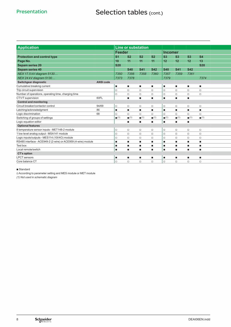
Application Line or substation Feeder Incomer
Protection and control type S1 S2 S2 S2 S3 S3 S3 S4 Page No. 10 11 11 11 12 12 12 13 Sepam series 20 S20 S20 Sepam series 40 S40 S41 S42 S40 S41 S42 NEX 17.5 kV diagram 5130… 7350 7356 7358 7360 7357 7359 7361 NEX 24 kV diagram 5130… 7373 7378 7379 7374 Protection function ANSI code
Phase overcurrent 50/51 b b b b b b b b
Voltage-restrained phase overcurrent 50V/51V Earth fault, sensitive earth fault
50N/51N 50G/51G b b b b b b b b
Breaker failure 50BF b b b b b b
Negative sequence/unbalance 46 b b b b b b b b
Directional phase overcurrent 67 b (1) b
Directional earth fault 67N/67NC b b b b
Directional active overpower 32P b (1) b (1) b b
Directional reactive overpower 32Q/40 Thermal overload 49RMS Phase undercurrent 37 Excessive starting time, locked rotor 48/51LR/14 Starts per hour 66 Positive sequence undervoltage 27D Remanent undervoltage 27R Undervoltage 27/27S b b b b b b
Overvoltage 59 b b b b b b
Neutral voltage displacement 59N b (1) b (1) b (1) b b b
Negative sequence overvoltage 47 b (1) b (1) b (1) b b b
Overfrequency 81H b (1) b (1) b (1) b b b
Underfrequency 81L b (1) b (1) b (1) b b b
Rate of change of frequency 81R Recloser (4 cycles) 79 v v v v v
Temperature monitoring (8 to 16 RTDs, 2 set points per RTD) 38/49T Thermostat/Buchholz/DGPT Measurement and diagnostic
Phase current I1; I2; I3 RMS, residual current I0 b b b b b b b b
Average current I1; I2; I3; peak demand current IM1, IM2, IM3 b b b b b b b b
Voltage U21; U32; U13; V1; V2; V3; residual voltage V0 b b b b b b
Positive sequence voltage Vd/rotation direction; neg. seq. voltage Vi (only S40) b b b b b b
Frequency b b b b b b
Active; reactive and apparent power P. Q. S Peak demand power PM. QM Power factor
b b b b b b
Calculated active and reactive energy ( +/-W.h. +/- var.h) b b b b b b
Active and reactive energy by pulse counting ( +/-W.h. +/- var.h) v (1) v (1) v (1) v (1) v (1) v (1)
Temperature Network and machine diagnosis
Tripping context b b b b b b
Tripping current Trip1; Trip2; Trip3; Trip0 b b b b b b b b
Unbalance ratio/negative sequence current Ii b b b b b b b b
Phase displacement ϕ0; ϕ1; ϕ2; ϕ3 b b b b b b
Disturbance recording b b b b b b b b
Thermal capacity used Remaining operating time before overload tripping Waiting time after overload tripping Running hours counter/operating time Start current and time Start inhibit time delay, number of starts before inhibition
b Standard v According to parameter setting and MES module or MET module (1) Not used in schematic diagram
DEAI06EN.indd 6

Bus tie Bus riser Busbar VT’s Transformer Motor Generator Feeder Incomer Feeder Incomer
S5 S6 B2 B1 B1 T1 T2 T3 T3 T6 T4 T4 T5 T5 M1 M2 G1 14 15 16 17 17 18 19 20 20 21 22 22 23 23 24 25 26 S20 B22 B21 B22 T20 T20 M20
S40 T40 T42 T40 T40 T42 T40 T42 M41 G40 7354 7355 7351 7352 7362 7365 7363 7366 7364 7367 7353 7368 7369
7372 7377 7371 7370 7375 7376 7380 7382 7381 7383
b b b b b b b b b b b b b b
b
b b b b b b b b b b b b b b
b b b b b b b b b b b
b b b b b b b b b b b b
b (1) b b
b b b b
b b
b b
b b b b b b b b b b b b
b b
b b
b b
b b b b
b b b b
b b b b b b b b b b b b b
b b b b b b b b b b b b b
b (1) b b b b (1) b (1) b (1) b (1) b (1) b (1) b (1) b b
b (1) b (1) b b (1) b (1) b (1) b (1) b (1) b (1) b (1) b (1) b b
b (1) b b b b (1) b (1) b (1) b (1) b (1) b (1) b (1) b (1) b
b (1) b b b b (1) b (1) b (1) b (1) b (1) b (1) b (1) b (1) b
b
v v v v v v v
v v v v v
b b b b b b b b b b b b b b
b b b b b b b b b b b b b b
b b b b b b b b b b b b b
b b b b b b b b b b b b b
b b b b b b b b b b b b b
b b b b b b b b b b
b b b b b b b b b b
v (1) v (1) v (1) v (1) v (1) v (1) v (1) v (1) v (1) v (1)
v v v (1) v (1) v (1) v (1) v (1) v (1) v v v v
b b b b b b b b b b
b b b b b b b b b b b b b b
b b b b b b b b b b b b b b
b b b b b b b b b b
b b b b b b b b b b b b b b b b b
b b b b b b b b b b b b
b b b b b b b b b b b b
b b b b b b b b b b b b
b b b b b b b b b b b b
b b
b b
DEAI06EN.indd 7
Presentation Selection tables (cont.)
Application Line or substation Feeder Incomer
Protection and control type S1 S2 S2 S2 S3 S3 S3 S4 Page No. 10 11 11 11 12 12 12 13 Sepam series 20 S20 S20 Sepam series 40 S40 S41 S42 S40 S41 S42 NEX 17.5 kV diagram 5130… 7350 7356 7358 7360 7357 7359 7361 NEX 24 kV diagram 5130… 7373 7378 7379 7374 Switchgear diagnostic ANSI code
Cumulative breaking current b b b b b b b b
Trip circuit supervision v v v v v v v v
Number of operations, operating time, charging time v v v v v v v v
CT/VT supervision 60FL b b b b b b
Control and monitoring Circuit breaker/contactor control 94/69 v v v v v v v v
Latching/acknowledgment 86 b b b b b b b b
Logic discrimination 68 v v v v v v v v
Switching of groups of settings b (1) b (1) b (1) b (1) b (1) b (1) b (1) b (1)
Logic equation editor b b b b b b
Optional features 8 temperature sensor inputs - MET148-2 module v v v v v v v v
1 low level analog output - MSA141 module v v v v v v v v
Logic inputs/outputs - MES114 (10I/4O) module v v v v v v v v
RS485 interface - ACE949-2 (2-wire) or ACE959 (4-wire) module b b b b b b b b
Test box b b b b b b b b
Local remote/switch b b b b b b b b
CT’s option LPCT sensors b b b b b b b b
Core balance CT v v v v v v v v
b Standard v According to parameter setting and MES module or MET module (1) Not used in schematic diagram
DEAI06EN.indd 8
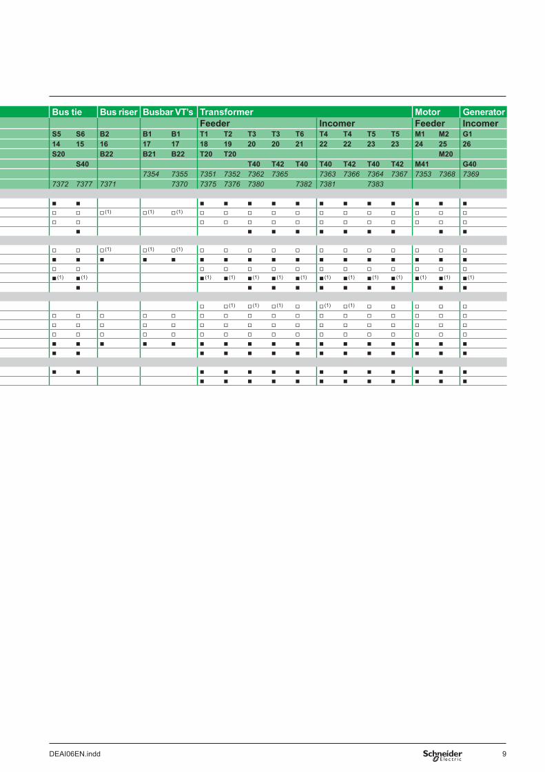
Bus tie Bus riser Busbar VT’s Transformer Motor Generator Feeder Incomer Feeder Incomer
S5 S6 B2 B1 B1 T1 T2 T3 T3 T6 T4 T4 T5 T5 M1 M2 G1 14 15 16 17 17 18 19 20 20 21 22 22 23 23 24 25 26 S20 B22 B21 B22 T20 T20 M20
S40 T40 T42 T40 T40 T42 T40 T42 M41 G40 7354 7355 7351 7352 7362 7365 7363 7366 7364 7367 7353 7368 7369
7372 7377 7371 7370 7375 7376 7380 7382 7381 7383
b b b b b b b b b b b b b b
v v v (1) v (1) v (1) v v v v v v v v v v v v
v v v v v v v v v v v v v v
b b b b b b b b b b
v v v (1) v (1) v (1) v v v v v v v v v v v v
b b b b b b b b b b b b b b b b b
v v v v v v v v v v v v v v
b (1) b (1) b (1) b (1) b (1) b (1) b (1) b (1) b (1) b (1) b (1) b (1) b (1) b (1)
b b b b b b b b b b
v v (1) v (1) v (1) v v (1) v (1) v v v v v
v v v v v v v v v v v v v v v v v
v v v v v v v v v v v v v v v v v
v v v v v v v v v v v v v v v v v
b b b b b b b b b b b b b b b b b
b b b b b b b b b b b b b b
b b b b b b b b b b b b b b
b b b b b b b b b b b b
DEAI06EN.indd 9

Application Substation feeder S1
b Detecting of unbalanced power supplied
b Protection against phase to phase Protection and phase to earth short circuits Sepam S20
b Recloser b It suited for integration into a supervisory system using Modbus serial interface. Several standard options are available to ensure maximum flexibility and cost effectiveness in meeting the requirements
bbb
50/51: overcurrent - IDMT, DT (4 settings) 50N/51N: earth fault - IDMT, DT (4 settings) 46: negative sequence overcurrent.
Measurement and diagnostic Sepam S20, LCD display LED (Light Emitting Diode)of different systems. bbbbbbb
Phase current: I1, I2, I3 RMS Residual current: I0 Average currents: I1, I2, I3 Peak demand phase currents Tripping currents: I1, I2, I3, I0 Unbalance ratio/negative sequence current Ii Disturbance recording.D
E56
380
Trip/close
Analog Output
Remote UMI
Modbus RS485
Substation feeder S1
(1) Close by communication and recloser (2) O11 reserved for closing order
(1) CT’s option
50/51 A 86 50N/51N MD 74 46 30
79(1)
68
bb
CLP1: LPCT sensors 100 A to 1250 ACore balance CT: CSH120 or CSH200.
Control Sepam S20 Basic MES114 module
apparatus (10 I/4 O) Cumulative breaking current b b
Trip CB output (O1) b b
Closing lockout (O2) b b
Logic discrimination block send (O3) b b
Watch dog (O4) b b
CB control (86) b b
CB open/closed status indication b
Number of operations, operating time b
Logic discrimination block receive b
External tripping b
Trip circuit supervision (74) b
Fault and alarm contact (O11(2) to O14) b
Recloser 4 cycles (79) b
External network time synchronization b
External trip b
Local/remote control selection b
Inhibition recloser b
Optional features bbbbbbb
Communication interface module, 2 wires (ACE949-2) Modbus Communication interface module, 4 wires (ACE959) Modbus One low level analog output (0-10 mA/ 4-20 mA/ 0-20 mA) MSA141 module Remote advanced UMI (type DSM303) Test box Local/remote switch Logic inputs and outputs module MES114 (10I/4O).
DEAI06EN.indd 10
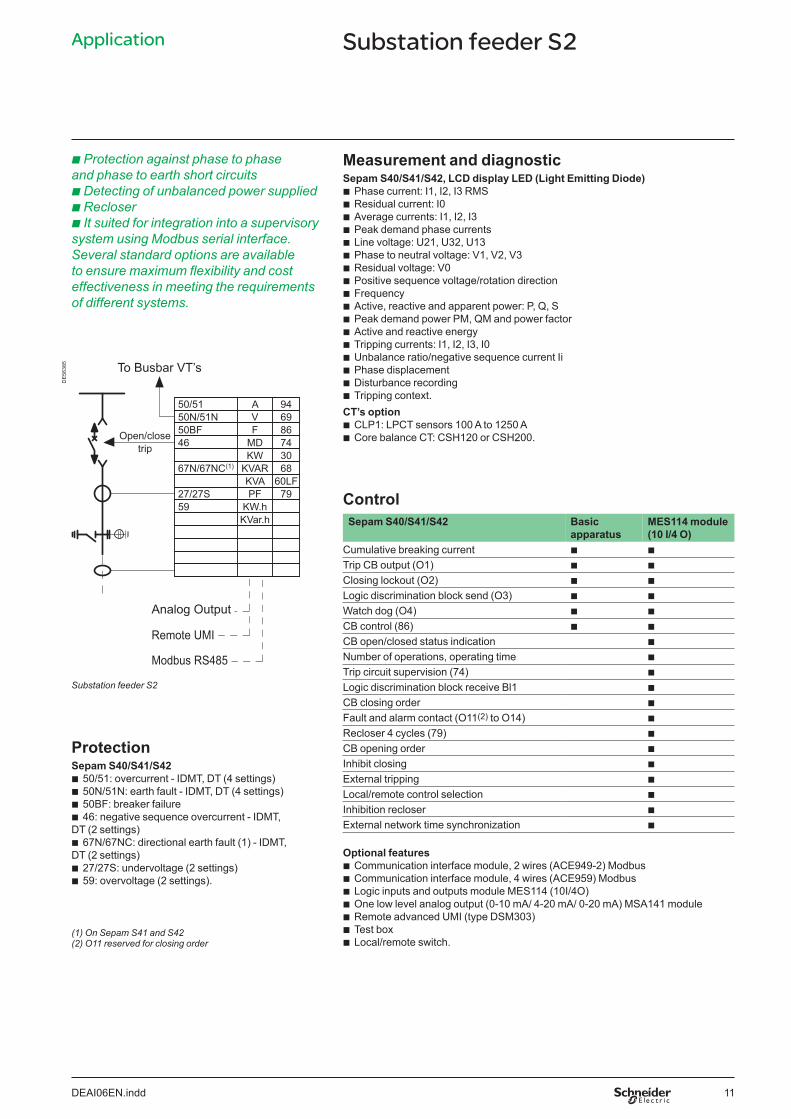
Application Substation feeder S2
b Protection against phase to phase Measurement and diagnosticand phase to earth short circuits Sepam S40/S41/S42, LCD display LED (Light Emitting Diode)b Detecting of unbalanced power supplied b
bbbbbbbbbbbbbbbb
Phase current: I1, I2, I3 RMS Residual current: I0 Average currents: I1, I2, I3 Peak demand phase currents Line voltage: U21, U32, U13 Phase to neutral voltage: V1, V2, V3 Residual voltage: V0 Positive sequence voltage/rotation direction Frequency Active, reactive and apparent power: P, Q, S Peak demand power PM, QM and power factor Active and reactive energy Tripping currents: I1, I2, I3, I0 Unbalance ratio/negative sequence current Ii Phase displacement Disturbance recording Tripping context.
b Recloser b It suited for integration into a supervisory system using Modbus serial interface. Several standard options are available to ensure maximum flexibility and cost effectiveness in meeting the requirements of different systems.
DE
5638
5 To Busbar VT’s
Open/close trip
Analog Output
Remote UMI
Modbus RS485
67N/67NC(1) KVAR 68 KW 30
46 MD 74 50BF F 86 50N/51N V 69 50/51 A 94
KVA 60LF 7927/27S PF
59 KW.h KVar.h
CT’s option bb
CLP1: LPCT sensors 100 A to 1250 ACore balance CT: CSH120 or CSH200.
Control Sepam S40/S41/S42 Basic MES114 module
apparatus (10 I/4 O) Cumulative breaking current b b
Trip CB output (O1) b b
Closing lockout (O2) b b
Logic discrimination block send (O3) b b
Watch dog (O4) b b
CB control (86) b b
CB open/closed status indication b
Number of operations, operating time b
Trip circuit supervision (74) b
Logic discrimination block receive Bl1 b
CB closing order b
Fault and alarm contact (O11(2) to O14) b
Recloser 4 cycles (79) b
CB opening order b
Inhibit closing b
Substation feeder S2
Protection Sepam S40/S41/S42 bbbb
50/51: overcurrent - IDMT, DT (4 settings) External tripping50N/51N: earth fault - IDMT, DT (4 settings) Local/remote control selection50BF: breaker failure Inhibition recloser46: negative sequence overcurrent - IDMT,
External network time synchronization
b
b
b
bDT (2 settings) b 67N/67NC: directional earth fault (1) - IDMT,
Optional featuresDT (2 settings) bb
27/27S: undervoltage (2 settings) 59: overvoltage (2 settings).
(1) On Sepam S41 and S42 (2) O11 reserved for closing order
bbbbbbb
Communication interface module, 2 wires (ACE949-2) Modbus Communication interface module, 4 wires (ACE959) Modbus Logic inputs and outputs module MES114 (10I/4O)One low level analog output (0-10 mA/ 4-20 mA/ 0-20 mA) MSA141 moduleRemote advanced UMI (type DSM303)Test boxLocal/remote switch.
DEAI06EN.indd 11

Application Substation incomer S3
b Protection against phase to phase Measurement and diagnosticand phase to earth short circuits Sepam S40/S41/S42, LCD display LED (Light Emitting Diode)b Detecting of unbalanced power supplied b
bbbbbbbbbbbbbbbb
Phase current: I1, I2, I3 RMS Residual current: I0 Average currents: I1, I2, I3 Peak demand phase currents Line voltage: U21, U32, U13 Phase to neutral voltage : V1, V2, V3 Residual voltage: V0 Positive sequence voltage/rotation direction Frequency Active, reactive and apparent power: P, Q, S Peak demand power PM, QM and power factor Active and reactive energy Tripping currents: I1, I2, I3, I0 Unbalance ratio/negative sequence current Ii Phase displacement Disturbance recording Tripping context.
b It suited for integration into a supervisory system using Modbus serial interface. Several standard options are available to ensure maximum flexibility and cost effectiveness in meeting the requirements of different systems.
DE
5638
6 Modbus RS485
Remote UMI Analog Output CT’s option
bb
CLP1: LPCT sensors 100 A to 1250 ACore balance CT: CSH120 or CSH200.
Substation incomer S3
Open/close trip
67N/67NC(2) 67(1)
KVAR 68 KW 30
46 MD 74 50BF F 86 50N/51N V 69 50/51 A 94
32P KVA 60LF 27/27S PF 59 59N
KW.h KVar.h
47 81H 81L
Control Sepam S40/S41/S42 Basic
apparatus MES114 module (10 I/4 O)
Cumulative breaking current b b
Trip CB output (O1) b b
Closing lockout (O2) b b
Logic discrimination block send (O3) b b
Watch dog (O4) b b
CB control (86) b b
CB open/closed status indication b
Number of operations, operating time b
Trip circuit supervision (74) b
Logic discrimination block receive Bl1 b
CB closing order b
Fault and alarm contact (O11(3) to O14) b
CB opening order b
Protection Sepam S40/S41/S42bbbb
50/51: overcurrent - IDMT, DT (4 settings) Inhibit closing50N/51N: earth fault - IDMT, DT (4 settings) External tripping50BF: breaker failure 46: negative sequence overcurrent - IDMT, Local/remote control selection
External network time synchronization
b
b
b
b
b DT (2 settings)
67: directional phase overcurrent (1) - IDMT, DT (2 settings) Optional features b 67N/67NC: directional earth fault (2) - IDMT, DT (2 settings) bbbbbbb
32P: directional active overpower (2)
27/27S: undervoltage (2 settings) 59: overvoltage (2 settings) 59N: neutral voltage displacement (2 settings) 47: negative sequence overvoltage 81H: overfrequency (2 settings) 81L: underfrequency (4 settings).
bbbbbbb
Communication interface module, 2 wires (ACE949-2) Modbus Communication interface module, 4 wires (ACE959) Modbus Logic inputs and outputs module MES114 (10I/4O) One low level analog output (0-10 mA/ 4-20 mA/ 0-20 mA) MSA141 module Remote advanced UMI (type DSM303) Test box Local/remote switch.
(1) On Sepam S42 only (2) On Sepam S41 and S42 (3) O11 reserved for closing order
DEAI06EN.indd 12

Application Substation incomer S4
b Protection against phase to phase Protection and phase to earth short circuits Sepam S20b Detecting of unbalanced power supplied b It suited for integration into a supervisory system using Modbus serial interface. Several standard options are available to ensure maximum flexibility and cost effectiveness in meeting the requirements of different systems.
bbb
50/51: overcurrent - IDMT, DT (4 settings) 50N/51N: earth fault - IDMT, DT (4 settings) 46: negative sequence overcurrent.
Measurement and diagnostic Sepam S20, LCD display LED (Light Emitting Diode)
DE
5638
1 Modbus RS485
Remote UMI
bbbbbbb
Phase current: I1, I2, I3 RMS Residual current: I0 Average currents: I1, I2, I3 Peak demand phase currents Tripping currents: I1, I2, I3, I0 Unbalance ratio/negative sequence current Ii Disturbance recording.
Analog Output CT’s option bb
CLP1: LPCT sensors 100 A to 1250 ACore balance CT: CSH120 or CSH200.
Substation incomer S4
(1) Close by communication and recloser (2) O11 reserved for closing order
Open/close trip
68 30
MD 74 86
50N/51N 50/51 A
Control Sepam S20 Basic
apparatus MES114 module (10 I/4 O)
Cumulative breaking current b b
Trip CB output (O1) b b
Closing lockout (O2) b b
Logic discrimination block send (O3) b b
Watch dog (O4) b b
CB control (86) b b
CB open/closed status indication b
Number of operations, operating time b
Logic discrimination block receive b
External tripping b
Trip circuit supervision (74) b
Fault and alarm contact (O11(2) to O14) b
External network time synchronization b
External trip b
Local/remote control selection b
Inhibition recloser b
Optional features bbbbbbb
Communication interface module, 2 wires (ACE949-2) Modbus Communication interface module, 4 wires (ACE959) Modbus One low level analog output (0-10 mA/ 4-20 mA/ 0-20 mA) MSA141 module Remote advanced UMI (type DSM303) Test box Local/remote switch Logic inputs and outputs module MES114 (10I/4O).
DEAI06EN.indd 13
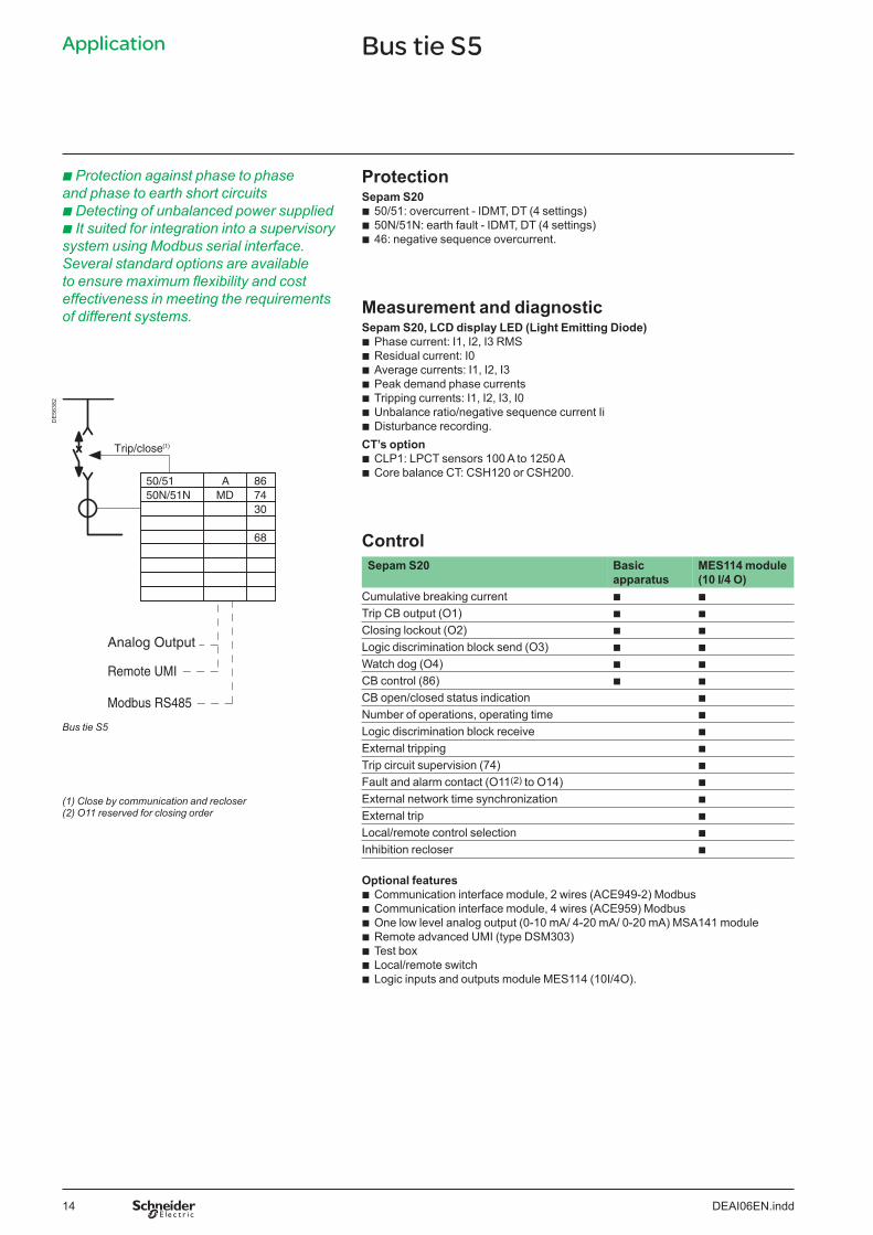
Application Bus tie S5
b Protection against phase to phase Protection and phase to earth short circuits Sepam S20b Detecting of unbalanced power supplied b It suited for integration into a supervisory system using Modbus serial interface. Several standard options are available to ensure maximum flexibility and cost effectiveness in meeting the requirements of different systems.
bbb
50/51: overcurrent - IDMT, DT (4 settings) 50N/51N: earth fault - IDMT, DT (4 settings) 46: negative sequence overcurrent.
Measurement and diagnostic Sepam S20, LCD display LED (Light Emitting Diode)
DE
5638
2
Trip/close
bbbbbbb
Phase current: I1, I2, I3 RMS Residual current: I0 Average currents: I1, I2, I3 Peak demand phase currents Tripping currents: I1, I2, I3, I0 Unbalance ratio/negative sequence current Ii Disturbance recording.
(1) CT’s option bb
CLP1: LPCT sensors 100 A to 1250 ACore balance CT: CSH120 or CSH200.
50/51 A 86 50N/51N MD 74
30
68 Control Sepam S20 Basic MES114 module
apparatus (10 I/4 O) Cumulative breaking current b b
Trip CB output (O1) b b
Closing lockout (O2) b b
Logic discrimination block send (O3) b b
Watch dog (O4) b b
CB control (86) b b
CB open/closed status indication b
Number of operations, operating time b
Logic discrimination block receive b
External tripping b
Trip circuit supervision (74) b
Fault and alarm contact (O11(2) to O14) b
External network time synchronization b
External trip b
Local/remote control selection b
Inhibition recloser b
Analog Output
Remote UMI
Modbus RS485
Bus tie S5
(1) Close by communication and recloser (2) O11 reserved for closing order
Optional features bbbbbbb
Communication interface module, 2 wires (ACE949-2) Modbus Communication interface module, 4 wires (ACE959) Modbus One low level analog output (0-10 mA/ 4-20 mA/ 0-20 mA) MSA141 module Remote advanced UMI (type DSM303) Test box Local/remote switch Logic inputs and outputs module MES114 (10I/4O).
DEAI06EN.indd 14

Application Bus tie S6
b Protection against phase to phase Protection and phase to earth short circuits Sepam S40b Detecting of unbalanced power supplied b Recloser b It suited for integration into a supervisory system using Modbus serial interface. Several standard options are available to ensure maximum flexibility and cost effectiveness in meeting the requirements of different systems.
bbbb
50/51: overcurrent - IDMT, DT (4 settings) 50N/51N: earth fault - IDMT, DT (4 settings) 50BF: breaker failure 46: negative sequence overcurrent - IDMT, DT (2 settings).
Measurement and diagnostic Sepam S40, LCD display LED (Light Emitting Diode) bbbbbbbbbbbbbbbbb
Phase current: I1, I2, I3 RMS Residual current: I0 Average currents: I1, I2, I3 Peak demand phase currents Line voltage: U21, U32, U13 Phase to neutral voltage: V1, V2, V3 Residual voltage: V0 Positive sequence voltage/rotation direction Frequency Active, reactive and apparent power: P, Q, S Peak demand power PM, QM and power factor Active and reactive energy Tripping currents: I1, I2, I3, I0 Unbalance ratio/negative sequence current Ii Phase displacement Disturbance recording Tripping context.
CT’s option bb
CLP1: LPCT sensors 100 A to 1250 ACore balance CT: CSH120 or CSH200.
DE
5638
3 To Busbar VT’s
Open/close trip
KVAR 68 KW 30
46 MD 74 50BF F 86 50N/51N V 69 50/51 A 94
KVA 60LF PF
KW.h KVar.h
(1)
Analog Output
ControlRemote UMI Sepam S40Modbus RS485 Basic
apparatus MES114 module (10 I/4 O)
Cumulative breaking current b b
Trip CB output (O1) b b
Closing lockout (O2) b b
Logic discrimination block send (O3) b b
Watch dog (O4) b b
CB control (86) b b
CB open/closed status indication b
Number of operations, operating time b
Trip circuit supervision (74) b
Logic discrimination block receive Bl1 b
CB closing order b
Fault and alarm contact (O11(2) to O14) b
CB opening order b
Inhibit closing b
External tripping b
Local/remote control selection b
Inhibition recloser b
External network time synchronization b
Bus tie S6
(1) Close by communication (2) O11 reserved for closing order
Optional features bbbbbbb
Communication interface module, 2 wires (ACE949-2) Modbus Communication interface module, 4 wires (ACE959) Modbus Logic inputs and outputs module MES114 (10I/4O) One low level analog output (0-10 mA/ 4-20 mA/ 0-20 mA) MSA141 module Remote advanced UMI (type DSM303) Test box Local/remote switch.
DEAI06EN.indd 15

Application Bus riser B2
b Detecting of variation in network voltage Protection or frequency Sepam B22b It suited for integration into a supervisory b
bbbbbbbb
27D/47: positive sequence undervoltage (2 sets) 27R: remanent undervoltage 27: phase to phase undervoltage (2 sets)
system using Modbus serial interface. Several standard options are available to ensure maximum flexibility and cost effectiveness in meeting the requirements of different systems.
27S: phase to neutral undervoltage 59: phase to phase overvoltage (2 sets) 59N: neutral voltage displacement (2 sets)81H: overfrequency81L: underfrequency (2 sets)81R: rate of change of frequency (B22 only).
Measurement and diagnostic Sepam B22, LCD display LED (Light Emitting Diode)
DE
5638
4
bbbbbb
Line voltage: U21, U32, U13 Phase to neutral voltage: V1, V2, V3 Residual voltage: V0 Positive sequence voltage/rotation direction Frequency Disturbance recording.
Control Sepam B22 Basic MES114 module
apparatus (10 I/4 O) Trip CB output (O1) b b
Closing lockout (O2) b b
Logic discrimination block send (O3) b b
Watch dog (O4) b b
Fault and alarm contact (O11 to O14) b b
External network time synchronization b
27D/47 V 86 27R F 30 27 27S 59 59N 81L 81H 81R (B22)
Analog Output
Remote UMI
Modbus RS485
Bus riser B2
Optional features bbbbbb
Communication interface module, 2 wires (ACE949-2) Modbus Communication interface module, 4 wires (ACE959) Modbus One low level analog output (0-10 mA/ 4-20 mA/ 0-20 mA) MSA141 module Remote advanced UMI (type DSM303) Test box Logic inputs and outputs module MES114 (10I/4O).
DEAI06EN.indd 16
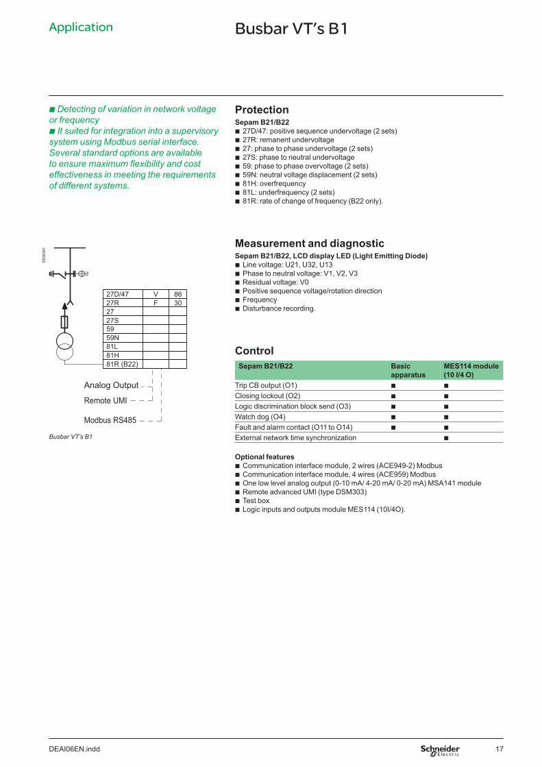
Application Busbar VT’s B1
b Detecting of variation in network voltage Protection or frequency Sepam B21/B22b It suited for integration into a supervisory b
bbbbbbbb
27D/47: positive sequence undervoltage (2 sets) 27R: remanent undervoltage 27: phase to phase undervoltage (2 sets)
system using Modbus serial interface. Several standard options are available to ensure maximum flexibility and cost effectiveness in meeting the requirements of different systems.
27S: phase to neutral undervoltage 59: phase to phase overvoltage (2 sets) 59N: neutral voltage displacement (2 sets)81H: overfrequency81L: underfrequency (2 sets)81R: rate of change of frequency (B22 only).
Measurement and diagnostic Sepam B21/B22, LCD display LED (Light Emitting Diode)
DE
5638
7
bbbbbb
Line voltage: U21, U32, U13 Phase to neutral voltage: V1, V2, V3 Residual voltage: V0 Positive sequence voltage/rotation direction Frequency Disturbance recording.
Control Sepam B21/B22 Basic MES114 module
apparatus (10 I/4 O) Trip CB output (O1) b b
Closing lockout (O2) b b
Logic discrimination block send (O3) b b
Watch dog (O4) b b
Fault and alarm contact (O11 to O14) b b
External network time synchronization b
27D/47 27R 27 27S 59 59N 81L 81H 81R (B22)
V F
86 30
Analog Output
Remote UMI
Modbus RS485
Busbar VT’s B1
Optional features bbbbbb
Communication interface module, 2 wires (ACE949-2) Modbus Communication interface module, 4 wires (ACE959) Modbus One low level analog output (0-10 mA/ 4-20 mA/ 0-20 mA) MSA141 module Remote advanced UMI (type DSM303) Test box Logic inputs and outputs module MES114 (10I/4O).
DEAI06EN.indd 17
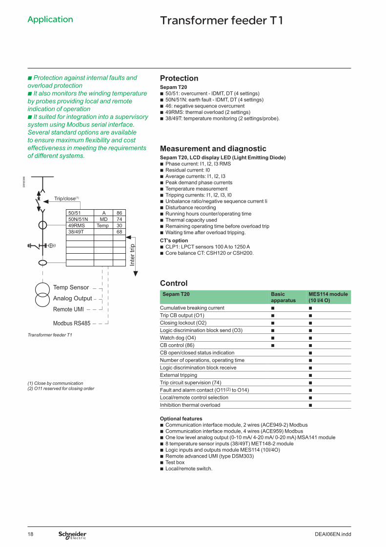
Application Transformer feeder T1
b Protection against internal faults and Protection overload protection Sepam T20b It also monitors the winding temperature b
bbbb
50/51: overcurrent - IDMT, DT (4 settings) 50N/51N: earth fault - IDMT, DT (4 settings) 46: negative sequence overcurrent
by probes providing local and remote indication of operation b It suited for integration into a supervisory
49RMS: thermal overload (2 settings) 38/49T: temperature monitoring (2 settings/probe).
system using Modbus serial interface. Several standard options are available to ensure maximum flexibility and cost effectiveness in meeting the requirements Measurement and diagnosticof different systems. Sepam T20, LCD display LED (Light Emitting Diode)
bbbbbbbbbbbb
Phase current: I1, I2, I3 RMS Residual current: I0 Average currents: I1, I2, I3 Peak demand phase currents Temperature measurement Tripping currents: I1, I2, I3, I0 Unbalance ratio/negative sequence current Ii Disturbance recording Running hours counter/operating time Thermal capacity used Remaining operating time before overload trip Waiting time after overload tripping.
DE
5638
8
Trip/close (1)
50/51 A 86 50N/51N MD 74 49RMS Temp 30 38/49T 68
Inte
r trip
CT’s option bb
CLP1: LPCT sensors 100 A to 1250 ACore balance CT: CSH120 or CSH200.
Control Sepam T20
Temp Sensor
Analog Output Basic apparatus
MES114 module (10 I/4 O)
Remote UMI Cumulative breaking current b b
Trip CB output (O1) b b
Modbus RS485 Closing lockout (O2) b b
Logic discrimination block send (O3) b b
Watch dog (O4) b b
CB control (86) b b
CB open/closed status indication b
Number of operations, operating time b
Logic discrimination block receive b
External tripping b
Trip circuit supervision (74) b
Fault and alarm contact (O11(2) to O14) b
Local/remote control selection b
Inhibition thermal overload b
Transformer feeder T1
(1) Close by communication (2) O11 reserved for closing order
Optional features bbbbbbbb
Communication interface module, 2 wires (ACE949-2) Modbus Communication interface module, 4 wires (ACE959) Modbus One low level analog output (0-10 mA/ 4-20 mA/ 0-20 mA) MSA141 module 8 temperature sensor inputs (38/49T) MET148-2 module Logic inputs and outputs module MES114 (10I/4O) Remote advanced UMI (type DSM303) Test box Local/remote switch.
DEAI06EN.indd 18

Application Transformer feeder T2
b Protection against internal faults and Protection overload protection Sepam T20b It also monitors the winding temperature b
bbbb
50/51: overcurrent - IDMT, DT (4 settings) 50N/51N: earth fault - IDMT, DT (4 settings) 46: negative sequence overcurrent
and Buchholz providing local and remote indication of operation b It suited for integration into a supervisory
49RMS: thermal overload (2 settings) Thermostat/Buchholz.
system using Modbus serial interface. Several standard options are available to ensure maximum flexibility and cost effectiveness in meeting the requirements Measurement and diagnosticof different systems. Sepam T20, LCD display LED (Light Emitting Diode)
DE
5638
9
Inte
r trip
Trip/close
Analog Output
Remote UMI
Modbus RS485
50/51 50N/51N 49RMS Thermos Buchholz
A MD
86 74 30 68
(1)
Transformer feeder T2
(1) Close by communication (2) O11 reserved for closing order
bbbbbbbbbbb
Phase current: I1, I2, I3 RMS Residual current: I0 Average currents: I1, I2, I3 Peak demand phase currents Tripping currents: I1, I2, I3, I0 Unbalance ratio/negative sequence current Ii Disturbance recording Running hours counter/operating time Thermal capacity used Remaining operating time before overload trip Waiting time after overload tripping.
CT’s option bb
CLP1: LPCT sensors 100 A to 1250 ACore balance CT: CSH120 or CSH200.
Control Sepam T20 Basic MES114 module
apparatus (10 I/4 O) Cumulative breaking current b b
Trip CB output (O1) b b
Closing lockout (O2) b b
Logic discrimination block send (O3) b b
Watch dog (O4) b b
CB control (86) b b
CB open/closed status indication b
Number of operations, operating time b
Logic discrimination block receive b
External tripping b
Trip circuit supervision (74) b
Fault and alarm contact (O11(2) to O14) b
External tripping (Buchholz) b
External tripping (Winding temperature) b
Buchholz alarm b
Winding temperature alarm b
Local/remote control selection b
Inhibition thermal overload b
Optional features bbbbbbb
Communication interface module, 2 wires (ACE949-2) Modbus Communication interface module, 4 wires (ACE959) Modbus One low level analog output (0-10 mA/ 4-20 mA/ 0-20 mA) MSA141 module Logic inputs and outputs module MES114 (10I/4O) Remote advanced UMI (type DSM303) Test box Local/remote switch.
DEAI06EN.indd 19
DE
5639
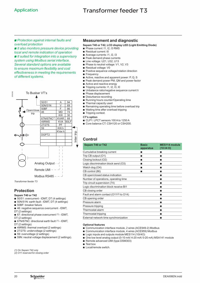
0 Application Transformer feeder T3
b Protection against internal faults and Measurement and diagnosticoverload protection Sepam T40 or T42, LCD display LED (Light Emitting Diode)b It also monitors pressure device providing b
bbbbbbbbbbbbbbbbbbbb
Phase current: I1, I2, I3 RMS Residual current: I0 Average currents: I1, I2, I3 Peak demand phase currents Line voltage: U21, U32, U13 Phase to neutral voltage: V1, V2, V3 Residual voltage: V0 Positive sequence voltage/rotation direction Frequency Active, reactive and apparent power: P, Q, S Peak demand power PM, QM and power factor Active and reactive energy Tripping currents: I1, I2, I3, I0 Unbalance ratio/negative sequence current Ii Phase displacement Disturbance recording Running hours counter/Operating time Thermal capacity used Remaining operating time before overload trip Waiting time after overload tripping Tripping context.
local and remote indication of operation b It suited for integration into a supervisory system using Modbus serial interface. Several standard options are available to ensure maximum flexibility and cost effectiveness in meeting the requirements of different systems.
To Busbar VT’s
Inte
r trip
Open/close trip
Analog Output
Remote UMI
Modbus RS485
67N/67NC(1) KVAR 68 KW 30
46 MD 74 50BF F 86 50N/51N V 69 50/51 A 94
49RMS KVA 60LF 27/27S PF 59 KW.h
KVar.h DGPT2
CT’s option bb
CLP1: LPCT sensors 100 A to 1250 ACore balance CT: CSH120 or CSH200.
Control Sepam T40 or T42 Basic
apparatus MES114 module (10 I/4 O)
Cumulative breaking current b b
Trip CB output (O1) b b
Closing lockout (O2) b b
Logic discrimination block send (O3) b b
Watch dog (O4) b b
CB control (86) b b
CB open/closed status indication b
Number of operations, operating time b
Trip circuit supervision (74) b
Logic discrimination block receive BI1 b
CB closing order b
Fault and alarm contact (O11(2) to O14) b
CB opening order b
Transformer feeder T3
Protection Sepam T40 or T42 bbbb
50/51: overcurrent - IDMT, DT (4 settings) 50N/51N: earth fault - IDMT, DT (4 settings) Pressure alarm 50BF: breaker failure Pressure tripping46: negative sequence overcurrent - IDMT, Thermostat alarm
b
b
b
b
b
DT (2 settings) Thermostat trippingb 67: directional phase overcurrent (1) - IDMT,
b DT (2 settings) External network time synchronization
67N/67NC: directional earth fault (1) - IDMT, DT (2 settings) Optional featuresbbbb
49RMS: thermal overload (2 settings) bbbbbbb
Communication interface module, 2 wires (ACE949-2) Modbus Communication interface module, 4 wires (ACE959) Modbus Logic inputs and outputs module MES114 (10I/4O) One low level analog output (0-10 mA/ 4-20 mA/ 0-20 mA) MSA141 module Remote advanced UMI (type DSM303)Test boxLocal/remote switch.
27/27S: undervoltage (2 settings) 59: overvoltage (2 settings) 59N: neutral voltage displacement (2 settings).
(1) On Sepam T42 only (2) O11 reserved for closing order
DEAI06EN.indd 20

DE
5639
0
Application Transformer feeder T6
b Protection against internal faults and Measurement and diagnosticoverload protection Sepam T40, LCD display LED (Light Emitting Diode)b It also monitors the windings by probes b
bbbbbbbbbbbbbbbbbbbb
Phase current: I1, I2, I3 RMS Residual current: I0 Average currents: I1, I2, I3 Peak demand phase currents Line voltage: U21, U32, U13 Phase to neutral voltage: V1, V2, V3 Residual voltage: V0 Positive sequence voltage/rotation direction Frequency Active, reactive and apparent power: P, Q, S Peak demand power PM, QM and power factor Active and reactive energy Tripping currents: I1, I2, I3, I0 Unbalance ratio/negative sequence current Ii Phase displacement Disturbance recording Running hours counter/operating time Thermal capacity used Remaining operating time before overload trip Waiting time after overload tripping Tripping context.
providing device local and remote indication of operation b It suited for integration into a supervisory system using Modbus serial interface. Several standard options are available to ensure maximum flexibility and cost effectiveness in meeting the requirements of different systems.
To Busbar VT’s
Inte
r trip
Open/close trip
Analog Output
Remote UMI
Modbus RS485
67N/67NC(1) KVAR 68 KW 30
46 MD 74 50BF F 86 50N/51N V 69 50/51 A 94
49RMS KVA 60LF 27/27S PF 59 KW.h
KVar.h DGPT2
CT’s option bb
CLP1: LPCT sensors 100 A to 1250 ACore balance CT: CSH120 or CSH200.
Control Sepam T40 Basic
apparatus MES114 module (10 I/4 O)
Cumulative breaking current b b
Trip CB output (O1) b b
Closing lockout (O2) b b
Logic discrimination block send (O3) b b
Watch dog (O4) b b
CB control (86) b b
CB open/closed status indication b
Number of operations, operating time b
Trip circuit supervision (74) b
Logic discrimination block receive BI1 b
CB closing order b
Fault and alarm contact (O11(2) to O14) b
CB opening order b
Transformer feeder T6
Protection Sepam T40 bbbb
50/51: overcurrent - IDMT, DT (4 settings) 50N/51N: earth fault - IDMT, DT (4 settings) Pressure alarm 50BF: breaker failure Pressure tripping46: negative sequence overcurrent - IDMT, Thermostat alarm
b
b
b
b
b
DT (2 settings) Thermostat trippingb 67: directional phase overcurrent (1) - IDMT,
b DT (2 settings) External network time synchronization
67N/67NC: directional earth fault (1) - IDMT, DT (2 settings) Optional featuresbbbbb
49RMS: thermal overload (2 settings) bbbbbbbb
Communication interface module, 2 wires (ACE949-2) Modbus Communication interface module, 4 wires (ACE959) Modbus Logic inputs and outputs module MES114 (10I/4O) One low level analog output (0-10 mA/ 4-20 mA/ 0-20 mA) MSA141 module 8 temperature sensor inputs (38/49T) MET148-2 module Remote advanced UMI user machine interface (type DSM303) Test box
27/27S: undervoltage (2 settings) 59: overvoltage (2 settings) 59N: neutral voltage displacement (2 settings) 38/49T: temperature monitoring.
(1) On Sepam T42 only (2) O11 reserved for closing order
Local/remote switch.
DEAI06EN.indd 21
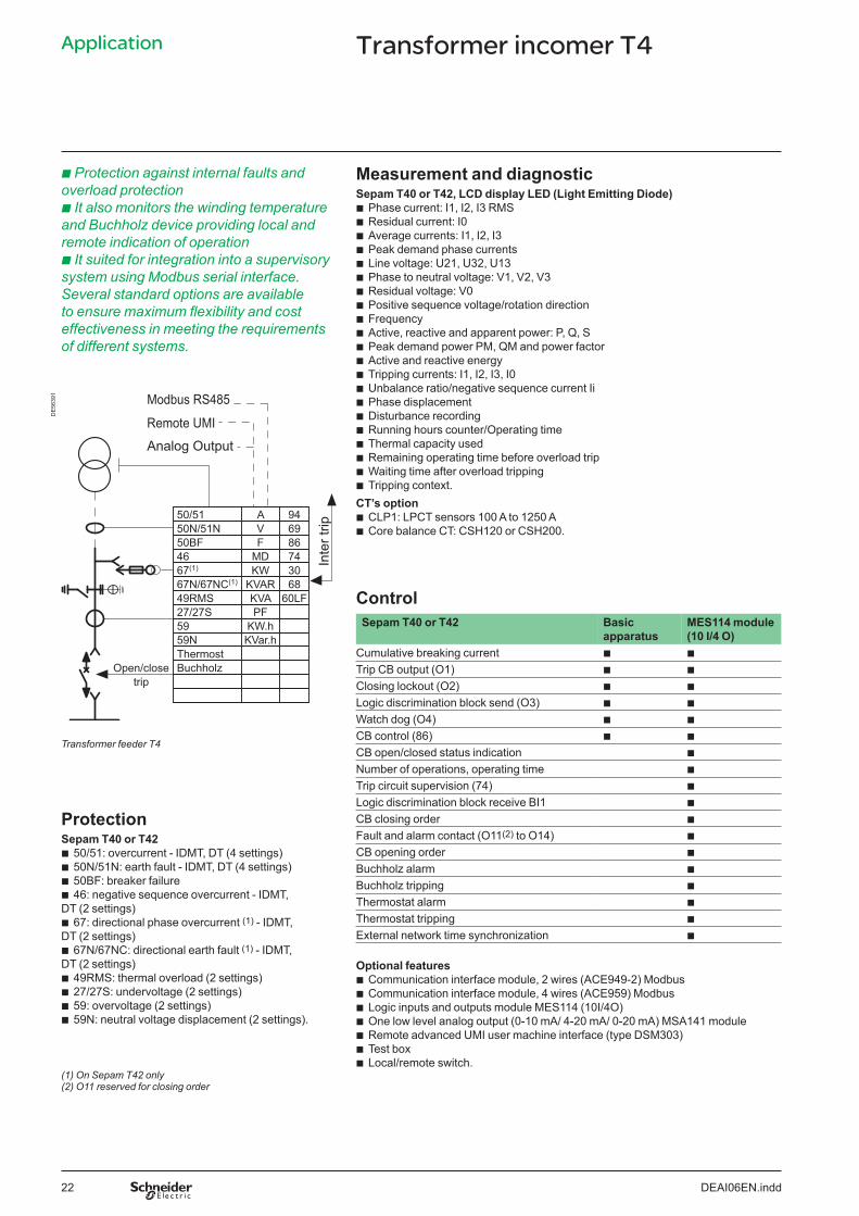
Application Transformer incomer T4
b Protection against internal faults and Measurement and diagnosticoverload protection Sepam T40 or T42, LCD display LED (Light Emitting Diode)b It also monitors the winding temperature b
bbbbbbbbbbbbbbbbbbbb
Phase current: I1, I2, I3 RMS Residual current: I0 Average currents: I1, I2, I3 Peak demand phase currents Line voltage: U21, U32, U13 Phase to neutral voltage: V1, V2, V3 Residual voltage: V0 Positive sequence voltage/rotation direction Frequency Active, reactive and apparent power: P, Q, S Peak demand power PM, QM and power factor Active and reactive energy Tripping currents: I1, I2, I3, I0 Unbalance ratio/negative sequence current Ii Phase displacement Disturbance recording Running hours counter/Operating time Thermal capacity used Remaining operating time before overload trip Waiting time after overload tripping Tripping context.
CT’s option bb
CLP1: LPCT sensors 100 A to 1250 ACore balance CT: CSH120 or CSH200.
Control Sepam T40 or T42 Basic
apparatus MES114 module (10 I/4 O)
Cumulative breaking current b b
Trip CB output (O1) b b
Closing lockout (O2) b b
Logic discrimination block send (O3) b b
Watch dog (O4) b b
CB control (86) b b
CB open/closed status indication b
Number of operations, operating time b
Trip circuit supervision (74) b
Logic discrimination block receive BI1 b
CB closing order b
Fault and alarm contact (O11(2) to O14) b
CB opening order b
and Buchholz device providing local and remote indication of operation b It suited for integration into a supervisory system using Modbus serial interface. Several standard options are available to ensure maximum flexibility and cost effectiveness in meeting the requirements of different systems.
DE
5639
1
Inte
r trip
Open/close trip
Analog Output
Remote UMI
Modbus RS485
67N/67NC(1) 67(1)
KVAR 68 KW 30
46 MD 74 50BF F 86 50N/51N V 69 50/51 A 94
49RMS KVA 60LF 27/27S PF 59 59N
KW.h KVar.h
Thermost Buchholz
Transformer feeder T4
Protection Sepam T40 or T42 bbbb
50/51: overcurrent - IDMT, DT (4 settings) 50N/51N: earth fault - IDMT, DT (4 settings) Buchholz alarm 50BF: breaker failure Buchholz tripping46: negative sequence overcurrent - IDMT, Thermostat alarm
b
b
b
b
b
DT (2 settings) Thermostat trippingb 67: directional phase overcurrent (1) - IDMT,
b DT (2 settings) External network time synchronization
67N/67NC: directional earth fault (1) - IDMT, DT (2 settings) Optional featuresbbbb
49RMS: thermal overload (2 settings) bbbbbbb
Communication interface module, 2 wires (ACE949-2) Modbus Communication interface module, 4 wires (ACE959) Modbus Logic inputs and outputs module MES114 (10I/4O) One low level analog output (0-10 mA/ 4-20 mA/ 0-20 mA) MSA141 module Remote advanced UMI user machine interface (type DSM303)Test boxLocal/remote switch.
27/27S: undervoltage (2 settings) 59: overvoltage (2 settings) 59N: neutral voltage displacement (2 settings).
(1) On Sepam T42 only (2) O11 reserved for closing order
DEAI06EN.indd 22

Application Transformer incomer T5
b Protection against internal faults and Measurement and diagnosticoverload protection Sepam T40 or T42, LCD display LED (Light Emitting Diode)b It also monitors the winding by probes b
bbbbbbbbbbbbbbbbbbbb
Phase current: I1, I2, I3 RMS Residual current: I0 Average currents: I1, I2, I3 Peak demand phase currents Line voltage: U21, U32, U13 Phase to neutral voltage: V1, V2, V3 Residual voltage: V0 Positive sequence voltage/rotation direction Frequency Active, reactive and apparent power: P, Q, S Peak demand power PM, QM and power factor Active and reactive energy Tripping currents: I1, I2, I3, I0 Unbalance ratio/negative sequence current Ii Phase displacement Disturbance recording Running hours counter/operating time Thermal capacity used Remaining operating time before overload trip Waiting time after overload tripping Tripping context.
providing device local and remote indication of operation b It suited for integration into a supervisory system using Modbus serial interface. Several standard options are available to ensure maximum flexibility and cost effectiveness in meeting the requirements of different systems.
DE
5639
2 Modbus RS485
Remote UMI Analog Output Temp Sensor
CT’s option
Transformer feeder T5
Inte
r trip
Open/close trip
67N/67NC(1) 67(1)
KVAR 68 KW 30
46 MD 74 50BF F 86 50N/51N V 69 50/51 A 94
49RMS KVA 60LF 27/27S PF 59 59N
KW.h KVar.h
38/49T Temp
bb Core balance CT: CSH120 or CSH200.
Control
CLP1: LPCT sensors 100 A to 1250 A
Sepam T40 or T42 Basic MES114 module apparatus (10 I/4 O)
Cumulative breaking current b b
Trip CB output (O1) b b
Closing lockout (O2) b b
Logic discrimination block send (O3) b b
Watch dog (O4) b b
CB control (86) b b
CB open/closed status indication b
Number of operations, operating time b
Trip circuit supervision (74) b
Logic discrimination block receive BI1 b
CB closing order b
Fault and alarm contact (O11(1) to O14) b
CB opening order b
Protection Sepam T40 or T42 bbbb
50/51: overcurrent - IDMT, DT (4 settings) 50N/51N: earth fault - IDMT, DT (4 settings) 50BF: breaker failure
Inhibit closing External tripping
b
b
b
b
b
46: negative sequence overcurrent - IDMT, Local/remote control selectionDT (2 settings) b 67: directional phase overcurrent - IDMT, Inhibition thermal overload
b DT (2 settings) External network time synchronization
67N/67NC: directional earth fault - IDMT, DT (2 settings) Optional featuresbbbbb
49RMS: thermal overload (2 settings) bbbbbbbb
Communication interface module, 2 wires (ACE949-2) Modbus Communication interface module, 4 wires (ACE959) Modbus Logic inputs and outputs module MES114 (10I/4O) One low level analog output (0-10 mA/ 4-20 mA/ 0-20 mA) MSA141 module
27/27S: undervoltage (2 settings) 59: overvoltage (2 settings) 59N: neutral voltage displacement (2 settings) 38/49T: temperature monitoring. 8 temperature sensor inputs (38/49T) MET148-2 module
Remote advanced UMI user machine interface (type DSM303)Test boxLocal/remote switch.
(1) O11 reserved for closing order
DEAI06EN.indd 23

Application Motor feeder M1
b Protection against internal faults and Protection loads faults Sepam M20b Monitoring of motor starting conditions b
bbbbbbb
50/51: overcurrent - IDMT, DT (4 settings) 50N/51N: earth fault - IDMT, DT (4 settings) 46: negative sequence overcurrent
and winding temperature by probes providing local and remote indication of operation b It suited for integration into a supervisory system using Modbus serial interface. Several standard options are available to ensure maximum flexibility and cost effectiveness in meeting the requirements of different systems.
49RMS: thermal overload (2 settings) 37: undercurrent 48/51LR: exces. start. time, locked rotor 66: starts per hour 38/49T: temperature monitoring.
Measurement and diagnostic Sepam M20, LCD display LED (Light Emitting Diode)
DE
5639
3
bbbbbbbbbbbbbb
Phase current: I1, I2, I3 RMS Residual current: I0 Average currents: I1, I2, I3 Peak demand phase currents Temperature measurement Tripping currents: I1, I2, I3, I0 Unbalance ratio/negative sequence current Ii Disturbance recording Running hours counter/operating time Thermal capacity used Remaining operating time before overload trip Waiting time after overload tripping Starting current and time/overloadStart inhibit time delay/numb. start before inhibition.
Trip/close (1)
50/51 A 86 50N/51N MD 74 49RMS Temp 30 46 68 37 48/51LR/14 66 38/49T
CT’s option bb
CLP1: LPCT sensors 100 A to 1250 ACore balance CT: CSH120 or CSH200.
M Temp Sensor
Analog Output
Remote UMI Control
Modbus RS485 Sepam M20 Basic MES114 module apparatus (10 I/4 O)Motor feeder M1
(1) Close by communication (2) O11 reserved for closing order
Cumulative breaking current b b
Trip CB output (O1) b b
Closing lockout (O2) b b
Logic discrimination block send (O3) b b
Watch dog (O4) b b
CB control (86) b b
CB open/closed status indication b
Number of operations, operating time b
External trip b
Trip circuit supervision (74) b
Fault and alarm contact (O11(2) to O14) b
Motor reacceleration b
Motor shaft rotation b
Local/remote control selection b
Inhibition thermal overload b
External network time synchronization b
Optional features bbbbbbbb
Communication interface module, 2 wires (ACE949-2) Modbus Communication interface module, 4 wires (ACE959) Modbus One low level analog output (0-10 mA/ 4-20 mA/ 0-20 mA) MSA141 module 8 temperature sensor inputs (38/49T) MET148-2 module Remote advanced UMI (type DSM303) Test box Local/remote switch Logic inputs and outputs module MES114 (10I/4O).
DEAI06EN.indd 24

Application Motor feeder M2
b Protection against internal faults, network Measurement and diagnosticrelated and loads faults Sepam M41, LCD display LED (Light Emitting Diode)b Monitoring of motor starting conditions b
bbbbbbbbbbbbbbbbbbbbbb
Phase current: I1, I2, I3 RMS Residual current: I0 Average currents: I1, I2, I3 Peak demand phase currents Line voltage: U21, U32, U13 Phase to neutral voltage: V1, V2, V3 Residual voltage: V0 Positive sequence voltage/rotation direction Frequency Active, reactive and apparent power: P, Q, S Peak demand power PM, QM and power factor Active and reactive energy Tripping currents: I1, I2, I3, I0 Unbalance ratio/negative sequence current Ii Phase displacement Disturbance recording Running hours counter/operating time Thermal capacity used Remaining operating time before overload trip Waiting time after overload tripping Starting current and time Start inhibit time delay/number of start before inhibition Tripping context.
and the winding temperature b It suited for integration into a supervisory system using Modbus serial interface. Several standard options are available to ensure maximum flexibility and cost effectiveness in meeting the requirements of different systems.
DE
5639
4 To Busbar VT’s
67N/67NC KW 30Open/close
50/51 A 94 50N/51N V 69 50BF F 86 46 MD 74
32P KVAR 68trip 32Q/40 KVA 60LF 49RMS PF
CT’s option 37 KW.h bb
CLP1: LPCT sensors 100 A to 1250 A Core balance CT: CSH120 or CSH200.
Control Sepam M41 Basic MES114 module
apparatus (10 I/4 O) Cumulative breaking current b b
Trip CB output (O1) b b
Closing lockout (O2) b b
Logic discrimination block send (O3) b b
Watch dog (O4) b b
CB control (86) b b
CB open/closed status indication b
Number of operations, operating time b
Trip circuit supervision (74) b
Motor rotation detection b
CB closing order b
Fault and alarm contact (O11(1) to O14) b
48/51LR/14 KVar.h 66 Temp 27D 27R 27/27S 59 59N 47 38/49T
M Temp Sensor
Analog Output
Remote UMI
Modbus RS485 Motor feeder M2
Protection Sepam M41
50/51: overcurrent - IDMT, DT (4 settings) bbbbb
CB opening order b
Inhibit closing b
External tripping b
Local/remote control selection b
Inhibition thermal overload b
50N/51N: earth fault - IDMT, DT (4 settings) 50BF: breaker failure 46: negative sequence overcurrent 67N/67NC: directional earth fault - IDMT,
DT (2 settings) bbbbbbbbbbbbb
32P: directional active overpower External network time synchronization b32Q/40: directional reactive overpower
49RMS: thermal overload (2 settings) 37: phase undercurrent 48/51LR/14: exces. start. time, locked rotor 66: starts per hour
Optional features bbbbbbbb
Communication interface module, 2 wires (ACE949-2) Modbus Communication interface module, 4 wires (ACE959) Modbus Logic inputs and outputs module MES114 (10I/4O) 27D: positive sequence undervoltage (2 settings)
27R: remanent undervoltage 27/27S: undervoltage (2 settings) 59: overvoltage (2 settings) 59N: neutral voltage displacement (2 settings) 47: negative sequence overvoltage 38/49T: temperature monitoring.
One low level analog output (0-10 mA/ 4-20 mA/ 0-20 mA) MSA141 module 8/16 temperature sensors inputs MET148-2 module Remote advanced UMI (type DSM303) Test box Local/remote switch.
(1) O11 reserved for closing order
DEAI06EN.indd 25

Application Generator incomer G1
b Protection against faults, network and Measurement and diagnosticloads faults Sepam G40, LCD display LED (Light Emitting Diode)b Monitoring of winding temperature b
bbbbbbbbbbbbbbbbbbbb
Phase current: I1, I2, I3 RMS Residual current: I0 Average currents: I1, I2, I3 Peak demand phase currents Line voltage: U21, U32, U13 Phase to neutral voltage: V1, V2, V3 Residual voltage: V0 Positive sequence voltage/rotation direction Frequency Active, reactive and apparent power: P, Q, S Peak demand power PM, QM and power factor Active and reactive energy Tripping currents: I1, I2, I3, I0 Unbalance ratio/negative sequence current Ii Phase displacement Disturbance recording Running hours counter/operating time Thermal capacity used Remaining operating time before overload trip Waiting time after overload tripping Tripping context.
b It suited for integration into a supervisory system using Modbus serial interface. Several standard options are available to ensure maximum flexibility and cost effectiveness in meeting the requirements of different systems.
DE
5639
5
G
46 KW 30Open/close
50/51 A 94 50V/51V V 69 50G/51G F 86 50BF MD 74
32P KVAR 68trip 32Q/40 KVA 60LF 49RMS PF 27/27S KW.h
CT’s option bb
CLP1: LPCT sensors 100 A to 1250 A Core balance CT: CSH120 or CSH200.
Control
59 KVar.h 59N Temp 47 81H 81L 38/49T
Sepam G40 Basic MES114 module apparatus (10 I/4 O)
Cumulative breaking current b b
Trip CB output (O1) b b
Closing lockout (O2) b b
Logic discrimination block send (O3) b b
Watch dog (O4) b b
CB control (86) b b
CB open/closed status indication b
Number of operations, operating time b
Trip circuit supervision (74) b
Logic discrimination block receive Bl1 b
CB closing order b
Fault and alarm contact (O11(1) to O14) b
Temp Sensor
Analog Output
Remote UMI
Modbus RS485
Generator incomer G1
Protection Sepam G40
50/51: overcurrent - IDMT, DT (4 settings) bbbbbbbbbbbbbb
CB opening order b
b
b
b
b
b
External trippingLocal/remote control selection Inhibition thermal overloadExternal network time synchronization
Optional features
50G/51G: earth fault - IDMT, DT (4 settings) 50BF: breaker failure 46: negative sequence overcurrent32P: directional active overpower32Q/40: directional reactive overpower49RMS: thermal overload27/27S: undervoltage (2 settings)59: overvoltage (2 settings)59N: neutral voltage displacement (2 settings)
Inhibit closing
bbbbbbbb
Communication interface module, 2 wires (ACE949-2) Modbus Communication interface module, 4 wires (ACE959) Modbus Logic inputs and outputs module MES114 (10I/4O) One low level analog output (0-10 mA/ 4-20 mA/ 0-20 mA) MSA141 module 8/16 temperature sensors inputs MET148-2 moduleRemote advanced UMI (type DSM303)Test boxLocal/remote switch.
47: negative sequence overvoltage 81H: overfrequency (2 settings) 81L: underfrequency (4 settings) 38/49T: temperature monitoring.
(1) O11 reserved for closing order
DEAI06EN.indd 26


AR
T.96
0249
© S
chne
ider
Ele
ctric
Indu
strie
s S
AS
- A
ll rig
hts
rese
rved
Schneider Electric Industries SAS As standards, specifications and designs change from time to time, please ask for confirmation 89, boulevard Franklin Roosevelt of the information given in this publication. F-92505 Rueil-Malmaison Cedex Tel.: +33 (0)1 41 29 85 00 This document has been printed www.schneider-electric.com on ecological paper
Publishing: Schneider Electric Industries SAS Production: Graphème Printing:
DEAI06EN 05-2008