medium voltage cables- complete range of lv/mv/hv cables - different types and sizes of...
TRANSCRIPT
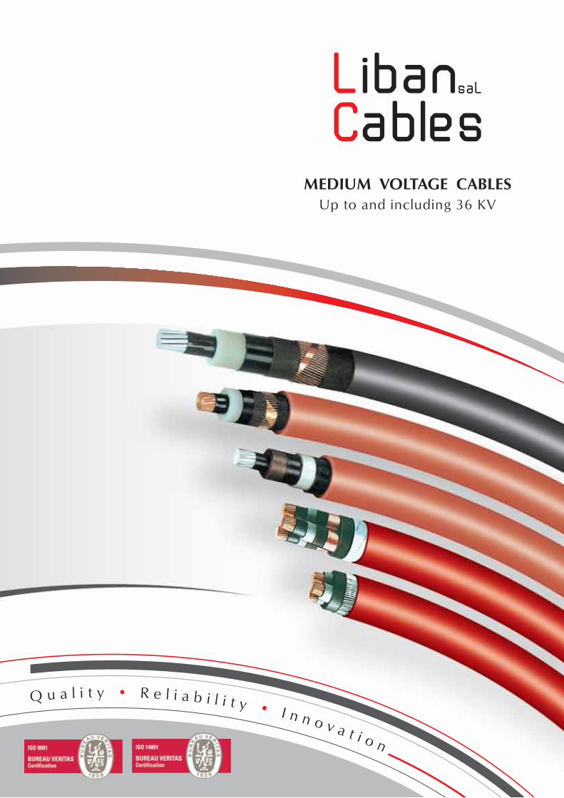
MEDIUM VOLTAGE CABLESUp to and including 36 KV


• OUR VALUES
Share Together Our Values Think Customer/Value People/Commit To Excellence/Take Action/Be Responsible/Work Globally
6 Values to share together:
Think Customer WE PUT OUR CUSTOMERS, AT THE CENTER OF OUR FOCUS, listening relentlessly to them, seeking to understand them fully, anticipating their changing needs and executing flawlessly to deliver superior products, services and value.
Value People We RECOGNIZE PEOPLE AS THE SOURCE OF OUR SUCCESS. We are reliable, open, honest, trustworthy and respectful to our colleagues and their diversity. We commit to Liban Cables Values. We expect fair treatment, progression and opportunities to develop our competencies.
Commit To Excellence WE ACHIEVE EXCELLENCE IN OUR PRODUCTS, process and services through shared knowledge, personal development, continuous improvement, safety and best-in-class execution.
Take Action WE BUILD TOGETHER A DYNAMIC CULTURE that encourages pro-activity, flexibility and innovation in the achievement of our strategic objectives. We anticipate and drive change.
Be Responsible WE DEMONSTRATE INTEGRITY by taking ownership for what is expected of us and full responsibility for our actions. We conduct business in a safe and ethical manner, respecting the environment and supporting the communities in which we operate.
Work Globally WE RECOGNIZE THE PRIMACY OF THE GROUP. We work together transversally, collaborating within and across organizational borders. We encourage openness, transparency, and the sharing of information and knowledge

C O N T E N T S
Page
• NOTICE
1• ABOUT US
2• QUALITY ASSURANCE
3• ENVIRONMENT POLICY
4• RECOMMENDED ORDERING PARAMETERS
5• GENERALITIES
5.1 - Choice of voltage
5.2 - Determination of the cross sectional area
5.3 - Current carrying capacities
5.3.1 - Buried cables
5.3.2 - Cables laid in the air
5.4 - Inductance
5.5 - Capacitance
5.6 - Conductors short circuit current
5.7 - Screen short circuit current
5.8 - Minimum bending radius
6• OUR TYPE AND CODE DESIGNATION
7• SINGLE AND THREE CORE MEDIUM VOLTAGE CABLES According to international standard IEC 60502
7.1 - 1.8/3 (3.6) KV Cables, XLPE insulated, PVC or PE Sheathed
7.2 - XLPE insulated, screened, PVC or PE sheathed cables for
voltages up to and including 36 KV.
7.3 - Insulated Bundled overhead conductors (Torsade)
12/20 (24) KV XLPE
8• TECHNICAL INFORMATION
8.1 - Formulae
8.2 - Conversion factors and units
7
8
9
9
10
11
11
11
11
12
13
15
15
15
16
16
17
18
18
24
42
46
46
47

7
• NOTICE
As this catalogue is not intended to cover all of LIBAN CABLES SAL possibilities in special
cables manufacturing, the hereafter listing of the types of cables is not restrictive but only
indicative of the main and most current types we manufacture.
On the other hand, our specification sheets are inspired mainly from International
Electrotechnical Commision Specification (IEC) only in order to conform with the sustained
trend, noticed both regionally and worldwide, towards these same IEC supposed to inspire
any further standardization approaches.
Whereas, in fact some special cables may require special conception, fully within the
capabilities of LIBAN CABLES SAL, ISO 9001 certified, precisely because in position to
conceive and tailor to your special needs.
That is why, while consulting this brochure, it is important to take into account that any
combination or change of the constructional details mentioned in this catalogue remain
feasible, on the basis of special conception and development, matching any special or
different specifications.
Finally, and within our policy of constant improvement, we reserve the right to alter any
part of the information contained in this publication without incurring any obligation. In all
cases this brochure being only indicative, and unless expressly agreed upon, it cannot be
considered by any mean as contractual document.
1 • ABOUT US
The Sheer magnitude and variety of cables used today... Requires a cable manufacturer
with vision... Along with extensive production & service capability...
Having more than 45 years of experience, Liban Cables provides complete expertise in
cables and cabling systems, starting with systems’ original conception and design of products
as well as solutions up to manufacturing a complete range of high quality cables. Liban Cables
facilities operate under ISO:9001 and ISO:14001 High Standards.
Vision
Providing our clients with the best possible services and products since their satisfaction is
our utmost priority.
Mission
Quality, Reliability and Innovation are the bases of our strategy.
CSR
Our Corporate Social Responsibility, Standards and Values are the key Factors that makes us
committed to eliminate all risks affecting environment as well as our employees’ safety.
Liban Cables offers:
- Wide choice of building and industrial cables
- Complete range of LV/MV/HV cables
- Different types and sizes of infrastructure cables (up to 220 KV)
Liban Cables, enhances both living and workplace. This variety of cables requires a cables
manufacturer with an exceptional experience.
Liban Cables was founded in 1967 by a group of Lebanese industrialists backed up by the
technical assistance of two international leading firms:
- Les Cables de Lyon - France (Became Alcatel afterwards & Nexans in 2000)
- Phelps Dodge - USA
Staffed with qualified engineers and highly skilled technicians, our plant is located in Nahr
Ibrahim at 45 KM North of Beirut, where cables are designed and manufactured according to
all international specifications: IEC, VDE, UTE, BS and others on customer request.
8
9
2 • QUALITY ASSURANCE
To satisfy our customers expectations for Quality, Safety, Reliability and Service; Liban Cables is committed to provide products and services of the highest possible Standards.
Raw material are continuously and repetitively tested from trial orders till the last batch received afterwards.
In addition to the final tests carried out on finished products, work in process, is already tested within two simultaneous procedures:
- A built-in quality control system is carried out by the production itself at any step of work in process.
- A parallel and contradictory procedure is also carried out on the same stages and products by independent inspectors reporting to the quality control service.
End users and/or third part inspection authorities are also constantly commissioning the finished products and assessing the strict conformity to ordered specifications.
Quality Management System:
Liban Cables has a Quality Control System implemented at the factory on all manufacturing stages and on our Final Product Stages. Developing innovation, achieving quality, meeting deadlines & providing services are our key priorities to satisfy our customers.
We make sure to increase production efficiency and speed delivery, while assuring the highest levels of quality, safety, security and reliability. All our facilities operate under the highest ISO:9001 Standards and we are fully committed to continuously improve the effectiveness of the Quality Management System, On-Time Delivery and Cost Effectiveness.
Quality is not another goal; It is at the core of our performance.
3 • ENVIRONMENT POLICY
Liban Cables is stepping up its efforts to reduce its impact on the environment via an environmental management system that is currently in operation at all of its sites.
Strict environmental management:
Liban Cables environmental and safety policy include a thorough assessment of industrial risks associated with the company’s products and manufacturing processes, a continuous improvement program and employee training courses on environmental best practices.
The Company Environmental Manual outlines the objectives, procedures and tools available to each site. A dedicated Intranet site is available allowing employees to access all of the Company environment-related data and share best practices, which are organized by subject matter. In addition, all our facilities operate under the highest ISO:14001 Standards.
The safety of our employees and visitors is our priority. We conduct business in a safe and ethical manner, respecting the environment and supporting the communities in which we operate.
Liban Cables is committed to the protection of the environment at locations where design, manufacturing, storage and delivery of electrical and communication cables are performed.
4 • RECOMMENDED ORDERING PARAMETERS
For prompt quotation / supplies please make sure your inquiries and your orders are securing the following data:
1 - International or Special Standard. (Alternatively, the precise usage of the cable.)
2 - Rated voltage.
3 - Copper or Aluminum conductors.
4 - Size of each conductor.
5 - Insulation material: XLPE or others.
6 - Number and identification of conductors.
7 - Other requirements.
8 - Packing.
9 - Required delivery time.
10 - Required validity.
10
11
5 • GENERALITIES
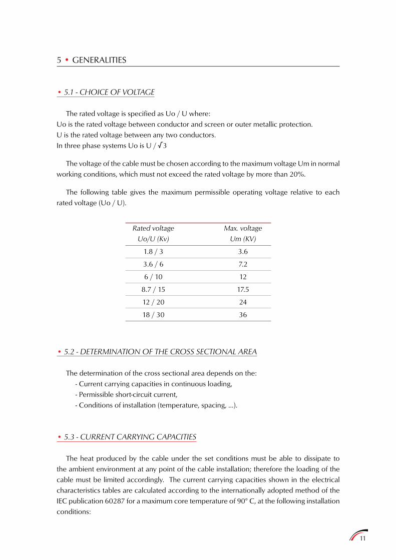
• 5.1 - CHOICE OF VOLTAGE
The rated voltage is specified as Uo / U where:Uo is the rated voltage between conductor and screen or outer metallic protection.U is the rated voltage between any two conductors.In three phase systems Uo is U / √3
The voltage of the cable must be chosen according to the maximum voltage Um in normal working conditions, which must not exceed the rated voltage by more than 20%.
The following table gives the maximum permissible operating voltage relative to each rated voltage (Uo / U).
• 5.2 - DETERMINATION OF THE CROSS SECTIONAL AREA
The determination of the cross sectional area depends on the:- Current carrying capacities in continuous loading,- Permissible short-circuit current,- Conditions of installation (temperature, spacing, ...).
• 5.3 - CURRENT CARRYING CAPACITIES
The heat produced by the cable under the set conditions must be able to dissipate to the ambient environment at any point of the cable installation; therefore the loading of the cable must be limited accordingly. The current carrying capacities shown in the electrical characteristics tables are calculated according to the internationally adopted method of the IEC publication 60287 for a maximum core temperature of 90° C, at the following installation conditions:
Rated voltage
Uo/U (Kv)
1.8 / 3
3.6 / 6
6 / 10
8.7 / 15
12 / 20
18 / 30
Max. voltage
Um (KV)
3.6
7.2
12
17.5
24
36
12
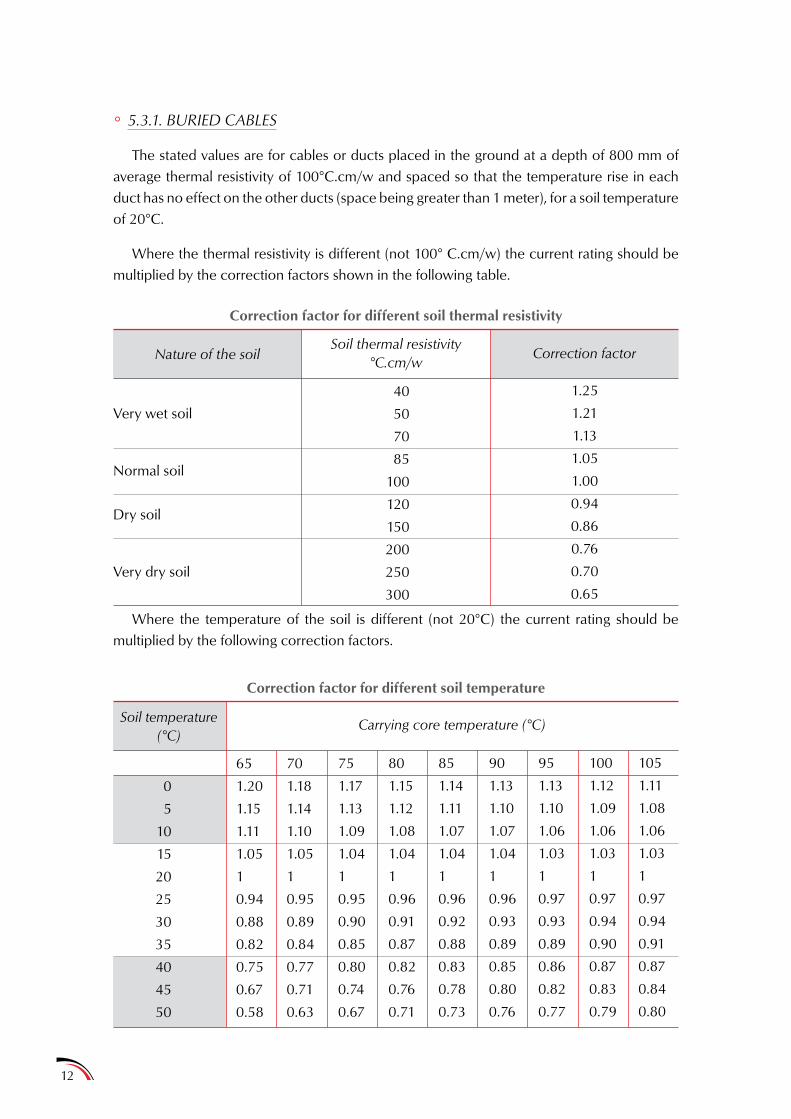
° 5.3.1. BURIED CABLES
The stated values are for cables or ducts placed in the ground at a depth of 800 mm of average thermal resistivity of 100°C.cm/w and spaced so that the temperature rise in each duct has no effect on the other ducts (space being greater than 1 meter), for a soil temperature of 20°C.
Where the thermal resistivity is different (not 100° C.cm/w) the current rating should be multiplied by the correction factors shown in the following table.
Correction factor for different soil thermal resistivity
Correction factor for different soil temperature
Nature of the soil
Soil temperature(°C)
Very wet soil
Normal soil
Dry soil
Very dry soil
0
5
10
15
20
25
30
35
40
45
50
40
50
70
85
100
120
150
200
250
300
65
1.20
1.15
1.11
1.05
1
0.94
0.88
0.82
0.75
0.67
0.58
70
1.18
1.14
1.10
1.05
1
0.95
0.89
0.84
0.77
0.71
0.63
75
1.17
1.13
1.09
1.04
1
0.95
0.90
0.85
0.80
0.74
0.67
80
1.15
1.12
1.08
1.04
1
0.96
0.91
0.87
0.82
0.76
0.71
85
1.14
1.11
1.07
1.04
1
0.96
0.92
0.88
0.83
0.78
0.73
90
1.13
1.10
1.07
1.04
1
0.96
0.93
0.89
0.85
0.80
0.76
95
1.13
1.10
1.06
1.03
1
0.97
0.93
0.89
0.86
0.82
0.77
100
1.12
1.09
1.06
1.03
1
0.97
0.94
0.90
0.87
0.83
0.79
105
1.11
1.08
1.06
1.03
1
0.97
0.94
0.91
0.87
0.84
0.80
Soil thermal resistivity°C.cm/w
Carrying core temperature (°C)
1.25
1.21
1.13
1.05
1.00
0.94
0.86
0.76
0.70
0.65
Correction factor
Where the temperature of the soil is different (not 20°C) the current rating should be multiplied by the following correction factors.
13
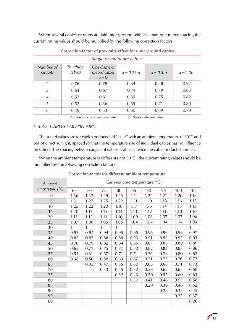
Correction factor of proximity effect for underground cables
Single or multicore cables
Correction factor for different ambient temperature
Number of circuits
Ambienttemperature (°C)
2
3
4
5
6
05
101520253035404550556065707580859095
100
0.76
0.64
0.57
0.52
0.49
1.361.311.251.201.131.0710.930.850.760.650.530.38
651.321.271.221.171.121.0610.940.870.790.710.610.500.35
1.291.251.201.151.111.0510.940.880.820.750.670.580.470.33
1.261.221.181.141.101.0510.950.890.840.770.710.630.550.450.32
1.241.211.171.131.091.0410.950.900.850.800.740.670.600.520.430.30
1.221.191.151.121.081.0410.960.910.870.820.760.710.650.580.500.410.29
1.211.181.141.111.071.0410.960.920.880.830.780.730.680.620.550.480.390.28
1.201.161.131.101.071.0410.960.930.890.850.800.760.710.650.600.530.460.380.27
1.181.151.131.101.061.0310.970.930.890.860.820.770.730.680.630.580.520.450.370.26
Touching cables
Carrying core temperature (°C)
0.79
0.67
0.61
0.56
0.53
0.84
0.74
0.69
0.65
0.60
0.88
0.79
0.75
0.71
0.69
0.92
0.85
0.82
0.80
0.78
One diameter spaced cables
a = Da = 0.25m a = 0.5m a = 1.0m
When several cables or ducts are laid underground with less than one meter spacing the current rating values should be multiplied by the following correction factors:
D = overall outer sheath diameter a = Space between cables
° 5.3.2. CABLES LAID “IN AIR”:
The stated values are for cables or ducts laid “in air” with an ambient temperature of 30°C and out of direct sunlight, spaced so that the temperature rise of individual cables has no influence on others. The spacing between adjacent cables is at least twice the cable or duct diameter.
When the ambient temperature is different ( not 30°C ) the current rating values should be multiplied by the following correction factors:
70 75 80 85 90 95 100 105
14
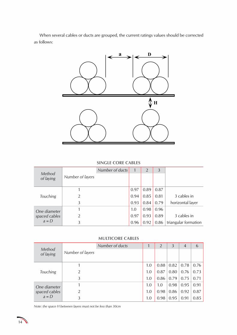
When several cables or ducts are grouped, the current ratings values should be corrected
as follows:
a D
H
SINGLE CORE CABLES
MULTICORE CABLES
Methodof laying
Methodof laying
Touching
Touching
One diameterspaced cables
a = D
One diameterspaced cables
a = D
Number of layers
Number of layers
Number of ducts
Number of ducts
1
2
3
1
2
3
1
2
3
1
2
3
1
1
0.97
0.94
0.93
1.0
0.97
0.96
1.0
1.0
1.0
1.0
1.0
1.0
2
2
0.89
0.85
0.84
0.98
0.93
0.92
0.88
0.87
0.86
1.0
0.98
0.98
3
3 4 6
0.87
0.81
0.79
0.96
0.89
0.86
0.82
0.80
0.79
0.98
0.86
0.95
0.78
0.76
0.75
0.95
0.92
0.91
0.76
0.73
0.71
0.91
0.87
0.85
3 cables in
horizontal layer
3 cables in
triangular formation
Note: the space H between layers must not be less than 30cm
15
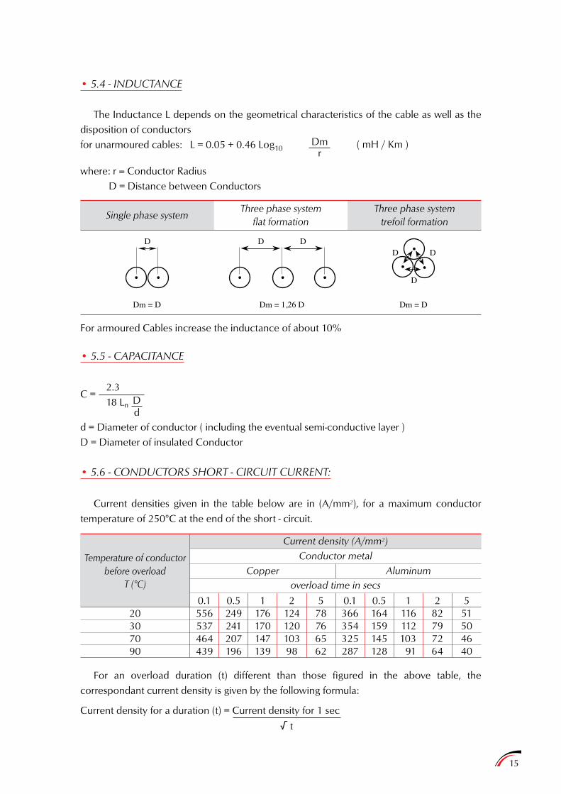
• 5.4 - INDUCTANCE
The Inductance L depends on the geometrical characteristics of the cable as well as the disposition of conductorsfor unarmoured cables: L = 0.05 + 0.46 Log10
where: r = Conductor Radius D = Distance between Conductors
Dmr
( mH / Km )
Single phase systemThree phase system
flat formationThree phase system
trefoil formation
For armoured Cables increase the inductance of about 10%
• 5.5 - CAPACITANCE
d = Diameter of conductor ( including the eventual semi-conductive layer )D = Diameter of insulated Conductor
• 5.6 - CONDUCTORS SHORT - CIRCUIT CURRENT:
Current densities given in the table below are in (A/mm2), for a maximum conductor temperature of 250°C at the end of the short - circuit.
Dm = D
D
Dm = 1,26 D Dm = D
D DD D
D
C =2.318 Ln D
d
Current density for a duration (t) = Current density for 1 sec
√ t
For an overload duration (t) different than those figured in the above table, the correspondant current density is given by the following formula:
Temperature of conductorbefore overload
T (°C)
20307090
556537464439
0.1249241207196
176170147139
12412010398
78766562
366354325287
164159145128
116112103
91
82797264
51504640
Conductor metal
overload time in secsCopper Aluminum
Current density (A/mm2)
0.5 1 2 5 0.1 0.5 1 2 5
16
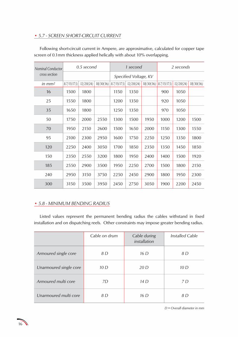
• 5.7 - SCREEN SHORT-CIRCUIT CURRENT
Following short-circuit current in Ampere, are approximative, calculated for copper tape screen of 0.1mm thickness applied helically with about 10% overlapping.
• 5.8 - MINIMUM BENDING RADIUS
Listed values represent the permanent bending radius the cables withstand in fixed installation and on dispatching reels. Other constraints may impose greater bending radius.
Nominal Conductorcross section
in mm2
16
25
35
50
70
95
120
150
185
240
300
1500
1550
1650
1750
1950
2100
2250
2350
2550
2950
3150
1800
1800
1800
2000
2150
2300
2400
2550
2900
3150
3500
2550
2600
2950
3050
3200
3500
3750
3950
1150
1200
1250
1300
1500
1600
1700
1800
1950
2250
2450
1350
1350
1350
1500
1650
1750
1850
1950
2250
2450
2750
1950
2000
2250
2350
2400
2700
2900
3050
900
920
970
1000
1150
1250
1350
1400
1500
1800
1900
1050
1050
1050
1200
1300
1350
1450
1500
1800
1950
2200
1500
1550
1800
1850
1920
2150
2300
2450
Specified Voltage, KV
8.7/15(17.5) 12/20(24) 18/30(36) 8.7/15(17.5) 12/20(24) 18/30(36) 8.7/15(17.5) 12/20(24) 18/30(36)
0.5 second
Cable on drum
D = Overall diameter in mm
Armoured single core
Unarmoured single core
Armoured multi core
Unarmoured multi core
8 D
10 D
7D
8 D
16 D
20 D
14 D
16 D
8 D
10 D
7 D
8 D
Cable duringinstallation
Installed Cable
1 second 2 seconds

17
6 • OUR TYPE AND CODE DESIGNATION
The type designation is a combination of abbreviations indicating the type, voltage and the main constructional elements of the cable as follows:
- The first symbol is the letter M for Medium voltage cables- The second symbol is a number (n) from 1 to 6 indicating the voltage as follows:
1 for 1.8/3 (3.6) kV2 for 3.6/6 (7.2) kV3 for 6/10 (12) kV4 for 8.7/15 (17.5) kV5 for 12/20 (24) kV6 for 18/30 (36) kV
- The third symbol is a letter indicating the type of metal of the conductor as follows:N for Copper conductorA for Aluminum conductor
- The fourth symbol is a number indicating the type of the insulation screen as follows:2 Semi-conductor bonded + copper tape3 Semi-conductor strippable + copper tape4 Semi-conductor bonded + copper wires5 Semi-conductor strippable + copper wires6 Semi-conductor bonbed collective copper wires7 Semi-conductor bonded + aluminum tape8 Semi-conductor bonded + lead9 Grooved semi-conductor
Note: For cables up to and including 3.6 kV where the insulation screen is not required, this number does not exist.
- The fifth, sixth and seventh abbreviations are eventual letters indicating the following:L For lead sheath global protectionB For steel tape armouringG For galvanized steel tape armouringR For galvanized round steel wire armouringF For flat steel wire armouringA For aluminum tape armouringW For round aluminum wire armouring
Examples: M3A2B: Medium voltage cable, 6/10 (12) kV, aluminum conductor, XLPEinsulation, bonded semi-conductor plus copper tape insulation screen, steel tape armour.
M5N3LR: Medium voltage cable, 12/20(24) kV, copper conductor, XLPEinsulation, strippable semi-conductor plus copper tape insulation screen, lead sheath, galvanized round steel wire armour.
18
7 • SINGLE CORE AND THREE CORE MEDIUM VOLTAGE CABLESAccording to international standard IEC 60502 - 1
7.1 • 1.8/3 (3.6) KV CABLES XLPE INSULATED, PVC OR PE SHEATHED
° 1. SCOPE
This specification covers single core cables and three core armoured or unarmoured
cables, rated at 1.8/3 (3.6) KV conforming to IEC 60502-1 Specifications.
° 2. CONSTRUCTION
2.1 Conductor
Plain, annealed electrolytic copper or Aluminum conductors, circular stranded,
conforming to the applicable requirements of IEC 60228.
2.2 Insulation
XLPE thermosetting material conforming to the applicable requirements of
IEC 60502-1 (flame retardant XLPE for specific applications).
2.3 Assembly
Insulated conductors are laid up, filled where necessary with non hygroscopic
material, and covered with an extruded thickness of thermoplastic material, or
binding tape.
2.4 Armour
Two layers of steel tape, (non magnetic tape for 1 core cables) conforming to the
applicable requirements of IEC 60502-1 recommendations.
Flat or round wires armouring can be provided upon specific customer requirements.
2.5 Sheath
PVC or PE (halogen free or fire retardant compound on special request) thermoplastic
material, conforming to the applicable requirements of IE 60502-1.
° 3. TESTS
All tests required by the IEC 60502-1 either on raw material or on finished products.
19
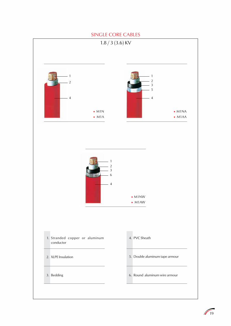
SINGLE CORE CABLES
1.8 / 3 (3.6) KV
1
2
4
1235
4
M1N
M1A••
M1NA
M1AA
M1NW
M1AW
1236
4
••
••
1.
2.
3.
4.
5.
6.
Stranded copper or aluminum conductor
XLPE Insulation
Bedding
PVC Sheath
Double aluminum tape armour
Round aluminum wire armour

20
THREE CORE CABLES
1.8 / 3 (3.6) KV
123
4
123
5
4
M1N
M1A
M1NFG
M1AFG
••
••
12
4
63
M1NB
M1AB
M1NR
M1AR
1237
4
••
••
1.
2.
3.
4.
5.
6.
7.
Stranded copper or aluminum
conductor
XLPE Insulation
Bedding
PVC Sheath
Double steel tape armour
Galvanized flat steel strip armour
with flat steel tape applied in helical
form
Galvanized round steel wire armour
Note: Different constructions remain possible on special request.
Nominalcross
section
Nominal Thickness of
InsulationInner
SheathOuterSheath Conductor Conductor
Copper cable Aluminum cable
ConductorInsulation Overall Cable Cable
Nominal Diameters Approximate net weight Lengthon
drum
Kg/Kmmm2 mm mm mm mm mm mm Kg/Km Kg/Km Kg/Km m
21
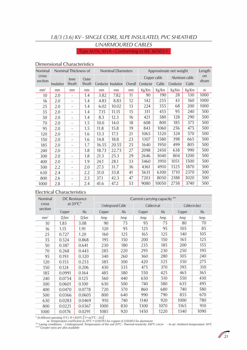
1.8/3 (3.6) KV - SINGLE CORE, XLPE INSULATED, PVC SHEATHEDUNARMOURED CABLES
Type M1N, M1A - Conforming to IEC 60502-1
Dimensional Characteristics
Electrical CharacteristicsNominal
crosssection
mm2 Ω/km Ω/km Amp Amp Amp Amp Amp Amp
DC Resistanceat 20°C*
Copper Alu
Cables in airUnderground Cable Cables in duct
CopperCopperCopper AluAluAlu
Current carrying capacity **
10162535507095
120150185240300400500630800
1000
10162535507095
120150185240300400500630800
1000
2.02.02.02.02.02.02.02.02.02.02.02.02.02.22.42.62.8
1.831.150.7270.5240.3870.2680.1930.1530.1240.09910.07540.06010.04700.03660.02830.02210.0176
-----------------
3.081.911.200.8680.6410.4430.3200.2530.2060.1640.1250.1000.07780.06050.04690.03670.0291
1.41.41.41.41.41.51.51.61.61.71.81.81.92.02.22.32.4
90120160195230285340385430485560630720800910
10001085
3.82 4.83 6.02 7.15 8.310.011.813.314.816.5518.7321.324.127.331.037.141.6
7595
125150180220260300335380440500570640740830920
7.82 8.8310.0211.1512.314.015.817.318.820.5522.7325.328.131.735.842.347.2
95125165200235295360420475550650740860990
114013001450
1112131516181921232527293336414753
7595
125150185230280325370425510580680790920
10701220
90142224311421608843
1065130716402098264634604361563172039080
80105140165200250305350395465550635740855
100011651340
190255355455580800
1060132015801950245030403910491063008050
10050
7085
105125155195240275310365430495580670780910
1090
28436895
128185256324398499638804
10511325171021882758
130160200240290375475570665805990
120015001870237030203740
100010001000
500500500500500500500500500500500500500500
* At different operating T(°C): R = R20°C 1+ a(T°C - 20)a: Temperature coefficient at 20°C = 0.00393 for copper & 0.00403 for aluminum
** Laying conditions: - Underground: Temperature of the soil 20°C - Thermal resistivity 100°C cm/w - In air: Ambient temperature 30°C*** Greater sizes are also available
Electrical CharacteristicsNominal
crosssection
mm2 Ω/km Ω/km Amp Amp Amp Amp Amp Amp
DC Resistanceat 20°C*
Copper Alu
Cables in airUnderground Cable Cables in duct
CopperCopperCopper AluAluAlu
Current carrying capacity **
22
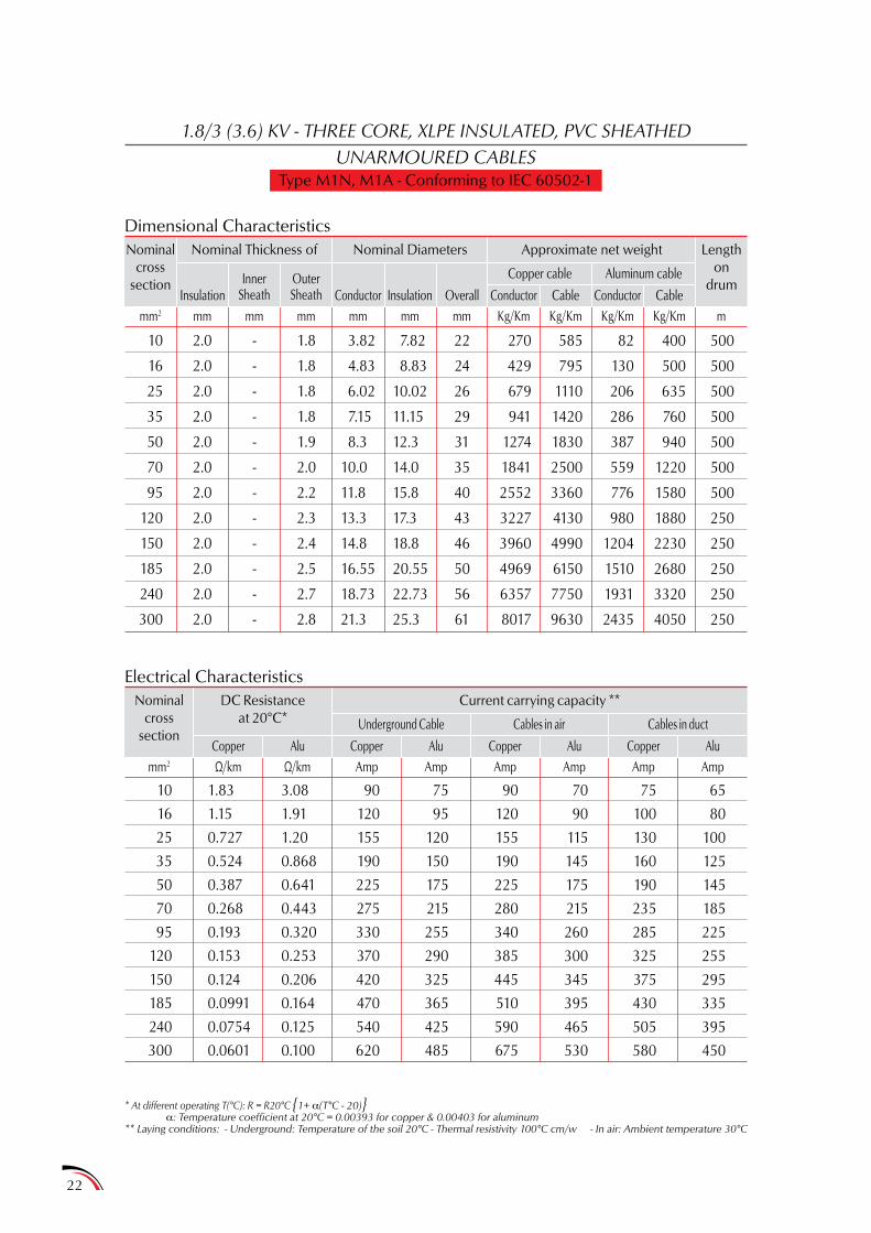
1.8/3 (3.6) KV - THREE CORE, XLPE INSULATED, PVC SHEATHEDUNARMOURED CABLES
Type M1N, M1A - Conforming to IEC 60502-1
Dimensional CharacteristicsNominal
crosssection
Nominal Thickness of
InsulationInner
SheathOuterSheath Conductor Conductor
Copper cable Aluminum cable
ConductorInsulation Overall Cable Cable
Nominal Diameters Approximate net weight Lengthon
drum
10
16
25
35
50
70
95
120
150
185
240
300
10
16
25
35
50
70
95
120
150
185
240
300
2.0
2.0
2.0
2.0
2.0
2.0
2.0
2.0
2.0
2.0
2.0
2.0
1.83
1.15
0.727
0.524
0.387
0.268
0.193
0.153
0.124
0.0991
0.0754
0.0601
-
-
-
-
-
-
-
-
-
-
-
-
3.08
1.91
1.20
0.868
0.641
0.443
0.320
0.253
0.206
0.164
0.125
0.100
1.8
1.8
1.8
1.8
1.9
2.0
2.2
2.3
2.4
2.5
2.7
2.8
90
120
155
190
225
275
330
370
420
470
540
620
3.82
4.83
6.02
7.15
8.3
10.0
11.8
13.3
14.8
16.55
18.73
21.3
75
95
120
150
175
215
255
290
325
365
425
485
7.82
8.83
10.02
11.15
12.3
14.0
15.8
17.3
18.8
20.55
22.73
25.3
90
120
155
190
225
280
340
385
445
510
590
675
22
24
26
29
31
35
40
43
46
50
56
61
70
90
115
145
175
215
260
300
345
395
465
530
270
429
679
941
1274
1841
2552
3227
3960
4969
6357
8017
75
100
130
160
190
235
285
325
375
430
505
580
585
795
1110
1420
1830
2500
3360
4130
4990
6150
7750
9630
65
80
100
125
145
185
225
255
295
335
395
450
82
130
206
286
387
559
776
980
1204
1510
1931
2435
400
500
635
760
940
1220
1580
1880
2230
2680
3320
4050
500
500
500
500
500
500
500
250
250
250
250
250
Kg/Kmmm2 mm mm mm mm mm mm Kg/Km Kg/Km Kg/Km m
* At different operating T(°C): R = R20°C 1+ a(T°C - 20)a: Temperature coefficient at 20°C = 0.00393 for copper & 0.00403 for aluminum
** Laying conditions: - Underground: Temperature of the soil 20°C - Thermal resistivity 100°C cm/w - In air: Ambient temperature 30°C
23
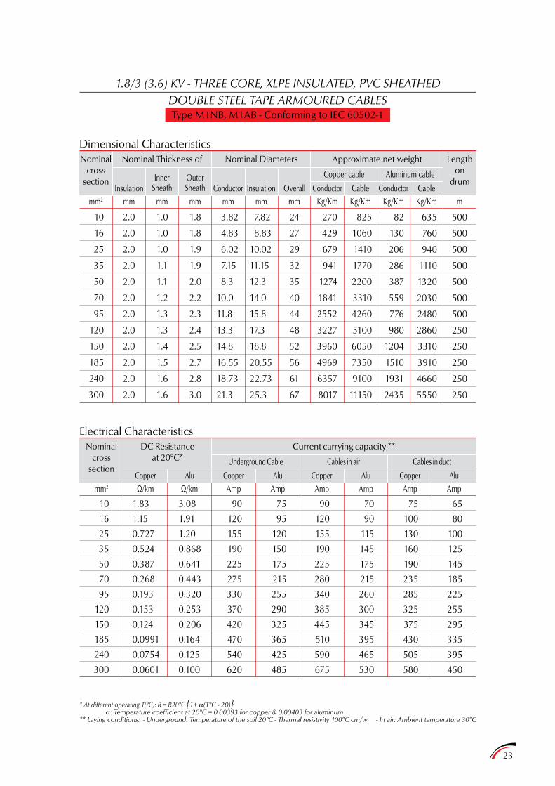
1.8/3 (3.6) KV - THREE CORE, XLPE INSULATED, PVC SHEATHEDDOUBLE STEEL TAPE ARMOURED CABLESType M1NB, M1AB - Conforming to IEC 60502-1
10
16
25
35
50
70
95
120
150
185
240
300
10
16
25
35
50
70
95
120
150
185
240
300
2.0
2.0
2.0
2.0
2.0
2.0
2.0
2.0
2.0
2.0
2.0
2.0
1.83
1.15
0.727
0.524
0.387
0.268
0.193
0.153
0.124
0.0991
0.0754
0.0601
1.0
1.0
1.0
1.1
1.1
1.2
1.3
1.3
1.4
1.5
1.6
1.6
3.08
1.91
1.20
0.868
0.641
0.443
0.320
0.253
0.206
0.164
0.125
0.100
1.8
1.8
1.9
1.9
2.0
2.2
2.3
2.4
2.5
2.7
2.8
3.0
90
120
155
190
225
275
330
370
420
470
540
620
3.82
4.83
6.02
7.15
8.3
10.0
11.8
13.3
14.8
16.55
18.73
21.3
75
95
120
150
175
215
255
290
325
365
425
485
7.82
8.83
10.02
11.15
12.3
14.0
15.8
17.3
18.8
20.55
22.73
25.3
90
120
155
190
225
280
340
385
445
510
590
675
24
27
29
32
35
40
44
48
52
56
61
67
70
90
115
145
175
215
260
300
345
395
465
530
270
429
679
941
1274
1841
2552
3227
3960
4969
6357
8017
75
100
130
160
190
235
285
325
375
430
505
580
825
1060
1410
1770
2200
3310
4260
5100
6050
7350
9100
11150
65
80
100
125
145
185
225
255
295
335
395
450
82
130
206
286
387
559
776
980
1204
1510
1931
2435
635
760
940
1110
1320
2030
2480
2860
3310
3910
4660
5550
500
500
500
500
500
500
500
250
250
250
250
250
Dimensional CharacteristicsNominal
crosssection
Nominal Thickness of
InsulationInner
SheathOuterSheath Conductor Conductor
Copper cable Aluminum cable
ConductorInsulation Overall Cable Cable
Nominal Diameters Approximate net weight Lengthon
drum
Kg/Kmmm2 mm mm mm mm mm mm Kg/Km Kg/Km Kg/Km m
Electrical CharacteristicsNominal
crosssection
mm2 Ω/km Ω/km Amp Amp Amp Amp Amp Amp
DC Resistanceat 20°C*
Copper Alu
Cables in airUnderground Cable Cables in duct
CopperCopperCopper AluAluAlu
Current carrying capacity **
* At different operating T(°C): R = R20°C 1+ a(T°C - 20)a: Temperature coefficient at 20°C = 0.00393 for copper & 0.00403 for aluminum
** Laying conditions: - Underground: Temperature of the soil 20°C - Thermal resistivity 100°C cm/w - In air: Ambient temperature 30°C
24
7.2 • XLPE INSULATED, SCREENED, PVC OR PE SHEATHED CABLES FOR VOLTAGES UP TO AND INCLUDING 36 KV
° 1. SCOPE
This specification covers single core cables and three core cables, armoured or unarmoured with or without lead sheath, rated at voltages up to and including 36 KV conforming toIEC 60502-2.
° 2. CONSTRUCTION
2.1 Conductor
Plain, annealed electrolytic copper or Aluminum conductors, circular stranded conforming to the applicable requirements of IEC 60228.
2.2 Conductor Screening
Semi-conducting layer or lapped, completely covering the conductors, conforming to the applicable to the requirements of IEC 60502-2 recommendations.
2.3 Insulation
XLPE thermosetting material conforming to the applicable requirements ofIEC 60502-2.
2.4 Insulation Screening
Semi conducting layer extruded (bonded or strippable) or lapped, completely covering the insulated conductors, and a copper or aluminum tape or wire completely covering the semi-conducting layer, conforming to the applicable requirements of IEC 60502-2 recommendations.
2.5 Assembly
Insulated and screened conductors are laid up, filled where necessary with non hygroscopic material and covered with an extruded thickness of thermoplastic material, or binding tape.
2.6 Lead Sheath (for special use)
Extruded lead alloy sheath, conforming to the applicable requirement of IEC 60502-2 recommendations.
2.7 Armour
Two layers of steel tape (non magnetic tape for 1 core cables), conforming to the applicable requirements of IEC 60502-2 recommendation.
Flat or round wires armouring can be provided upon specific customer requirements.
2.8 Sheath
PVC or PE (halogen free or fire retardant compound on special request)thermoplastic material conforming to the applicable requirements of IEC 60502-2.
° 3. TESTS
All tests required by the IEC 60502-2, either on raw materials or on finished products.

25
SINGLE CORE CABLES
From 6 to 36 KV
1
2
3
4
5
7
1
2
3
4
5
7
68
1
2
569
7
4
3
1
2
3
4
69
7
10
1.
2.
3.
4.
5.
6.
7.
8.
9.
10.
Stranded copper or aluminum conductor
Conductor screen
XLPE Insulation
Insulation screen
Copper or aluminum tapeor wires screen
Bedding
PVC sheath
Double aluminum tape armour
Round aluminum wire armour
Lead sheath / screen
M2N - M2A
M3N - M3A
M4N - M4A
M5N - M5A
M6N - M6A
M2NA - M2AA
M3NA - M3AA
M4NA - M4AA
M5NA - M5AA
M6NA - M6AA
M2NW - M2AW
M3NW - M3AW
M4NW - M4AW
M5NW - M5AW
M6NW - M6AW
M2NLW - M2ALW
M3NLW - M3ALW
M4NLW - M4ALW
M5NLW - M5ALW
M6NLW - M6ALW
•••••
•••••
•••••
•••••

26
M2NFG - M2AFG
M3NFG - M3AFG
M4NFG - M4AFG
M5NFG - M5AFG
M6NFG - M6AFG
•••••
M2NR - M2AR
M3NR - M3AR
M4NR - M4AR
M5NR - M5AR
M6NR - M6AR
•••••
M2NB - M2AB
M3NB - M3AB
M4NB - M4AB
M5NB - M5AB
M6NB - M6AB
•••••
M2N - M2A
M3N - M3A
M4N - M4A
M5N - M5A
M6N - M6A
•••••
M2NLR - M2ALR
M3NLR - M3ALR
M4NLR - M4ALR
M5NLR - M5ALR
M6NLR - M6ALR
•••••
1.
2.
3.
4.
5.
6.
7.
8.
9.
10.
11.
Stranded copper or aluminum conductor
Conductor screen
XLPE insulation
Insulation screen
Copper or aluminum tape or wires screen
Bedding
PVC sheath
Double steel tape armour
Galvanized flat steel strips armour with flat steel tape applied in helical form
Galvanized round steel wire armour
Lead sheath
Notes : 1 - Different constructions remain possible on special request. 2 - Lead sheathed cables are also available.
THREE CORE CABLES
From 6 to 36 KV
1
1
1
1
1
2
2
2
2
2
3
3
3
3
3
4
4
4
4
4
5
5
5
5
5
11
6 6
6
6
9 10
8
10
7
7
7
7
7
27
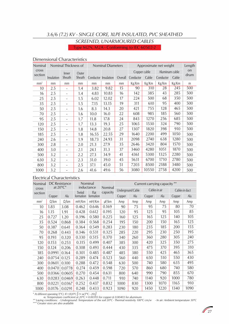
3.6/6 (7.2) KV - SINGLE CORE, XLPE INSULATED, PVC SHEATHEDSCREENED, UNARMOURED CABLES
Type M2N, M2A - Conforming to IEC 60502-2
Dimensional Characteristics
Electrical Characteristics
Nominalcross
section
mm2 Ω/km Ω/km mH/Km mH/Km µF/km Amp Amp Amp Amp Amp Amp
Nominal Thickness of
DC Resistanceat 20°C*
Nominalinductance
InsulationInner
Sheath
Copper
OuterSheath
AluTrefoil
formationFlat
formation
Conductor Conductor
Copper cable
Cables in airUnderground CableNominalcapacity
Aluminum cable
Cables in duct
Conductor
CopperCopperCopper
Insulation Overall Cable Cable
AluAluAlu
Nominal Diameters Approximate net weight
Current carrying capacity **
Lengthon
drum
10162535507095
120150185240300400500630800
1000
10162535507095
120150185240300400500630800
1000
2.52.52.52.52.52.52.52.52.52.52.62.83.03.23.23.23.2
1.831.150.7270.5240.3870.2680.1930.1530.1240.09910.07540.06010.04700.03660.02830.02210.0176
-----------------
3.081.911.200.8680.6410.4430.3200.2530.2060.1640.1250.1000.07780.06050.04690.03670.0291
1.41.41.51.51.61.61.71.71.81.81.92.02.12.22.32.52.6
90120160195230285340385430485560630720800910
10001090
3.82 4.83 6.02 7.15 8.310.011.813.314.816.5518.7321.324.127.331.037.141.6
7595
125150180220260300335380440500570640740830920
0.4620.4280.3960.3840.3640.3460.3300.3150.3080.3010.2890.2880.2740.2700.2630.2520.248
0.6460.6120.5800.5680.5490.5310.5150.4990.4930.4850.4740.4720.4590.4540.4480.4370.433
0.1690.1950.2250.2540.2830.3250.3700.4070.4440.4870.5230.5480.5980.6310.7110.8320.923
9.8210.8312.0213.1514.316.017.819.320.822.5524.9327.931.334.939.045.049.6
95125165200235295360420475550650740860990
114013001450
1516171920222425272931353741455156
7595
125150185230280325370425510580680790920
10701220
90142224311421608843
1065130716402098264634604361563172033080
80105140165200250305350395465550635740855
100011651340
310385500610755985
1270153018202200274034204280530067008500
10550
7085
105125155195240275310365430495580670780910
1090
28436895
128185256324398499638804
10511325171021882758
245285350400465560685790910
10501280157018702280278034804200
500500500500500500500500500500500500500500500500500
Kg/Kmmm2 mm mm mm mm mm mm Kg/Km Kg/Km Kg/Km m
* At different operating T(°C): R = R20°C 1+ a(T°C - 20)a: Temperature coefficient at 20°C = 0.00393 for copper & 0.00403 for aluminum
** Laying conditions: - Underground: Temperature of the soil 20°C - Thermal resistivity 100°C cm/w - In air: Ambient temperature 30°C*** Greater sizes are also available
Nominalcross
section
28
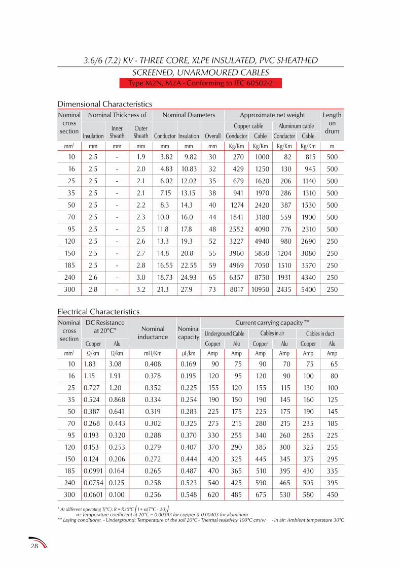
3.6/6 (7.2) KV - THREE CORE, XLPE INSULATED, PVC SHEATHEDSCREENED, UNARMOURED CABLES
Type M2N, M2A - Conforming to IEC 60502-2
Dimensional Characteristics
Electrical Characteristics
Nominalcross
section
Nominalcross
section
mm2 Ω/km Ω/km mH/Km µF/km Amp Amp Amp Amp Amp Amp
Nominal Thickness of
DC Resistanceat 20°C* Nominal
inductance
InsulationInner
Sheath
Copper
OuterSheath
Alu
Conductor Conductor
Copper cable
Cables in airUnderground CableNominalcapacity
Aluminum cable
Cables in duct
Conductor
CopperCopperCopper
Insulation Cable Cable
AluAluAlu
Nominal Diameters Approximate net weight
Current carrying capacity **
Lengthon
drum
10
16
25
35
50
70
95
120
150
185
240
300
10
16
25
35
50
70
95
120
150
185
240
300
2.5
2.5
2.5
2.5
2.5
2.5
2.5
2.5
2.5
2.5
2.6
2.8
1.83
1.15
0.727
0.524
0.387
0.268
0.193
0.153
0.124
0.0991
0.0754
0.0601
-
-
-
-
-
-
-
-
-
-
-
-
3.08
1.91
1.20
0.868
0.641
0.443
0.320
0.253
0.206
0.164
0.125
0.100
1.9
2.0
2.1
2.1
2.2
2.3
2.5
2.6
2.7
2.8
3.0
3.2
90
120
155
190
225
275
330
370
420
470
540
620
3.82
4.83
6.02
7.15
8.3
10.0
11.8
13.3
14.8
16.55
18.73
21.3
75
95
120
150
175
215
255
290
325
365
425
485
0.408
0.378
0.352
0.334
0.319
0.302
0.288
0.279
0.272
0.265
0.258
0.256
0.169
0.195
0.225
0.254
0.283
0.325
0.370
0.407
0.444
0.487
0.523
0.548
9.82
10.83
12.02
13.15
14.3
16.0
17.8
19.3
20.8
22.55
24.93
27.9
90
120
155
190
225
280
340
385
445
510
590
675
30
32
35
38
40
44
48
52
55
59
65
73
70
90
115
145
175
215
260
300
345
395
465
530
270
429
679
941
1274
1841
2552
3227
3960
4969
6357
8017
75
100
130
160
190
235
285
325
375
430
505
580
1000
1250
1620
1970
2420
3180
4090
4940
5850
7050
8750
10950
65
80
100
125
145
185
225
255
295
335
395
450
82
130
206
286
387
559
776
980
1204
1510
1931
2435
815
945
1140
1310
1530
1900
2310
2690
3080
3570
4340
5400
500
500
500
500
500
500
500
250
250
250
250
250
Kg/Kmmm2 mm mm mm mm mm mm Kg/Km Kg/Km Kg/Km m
* At different operating T(°C): R = R20°C 1+ a(T°C - 20)a: Temperature coefficient at 20°C = 0.00393 for copper & 0.00403 for aluminum
** Laying conditions: - Underground: Temperature of the soil 20°C - Thermal resistivity 100°C cm/w - In air: Ambient temperature 30°C
Overall
29
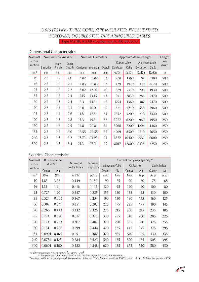
3.6/6 (7.2) KV - THREE CORE, XLPE INSULATED, PVC SHEATHEDSCREENED, DOUBLE STEEL TAPE ARMOURED CABLES
Type M2NB, M2AB - Conforming to IEC 60502-2
Dimensional Characteristics
Electrical Characteristics
Nominalcross
section
Nominalcross
section
mm2 Ω/km Ω/km mH/Km µF/km Amp Amp Amp Amp Amp Amp
Nominal Thickness of
DC Resistanceat 20°C* Nominal
inductance
InsulationInner
Sheath
Copper
OuterSheath
Alu
Conductor Conductor
Copper cable
Cables in airUnderground CableNominalcapacity
Aluminum cable
Cables in duct
Conductor
CopperCopperCopper
Insulation Overall Cable Cable
AluAluAlu
Nominal Diameters Approximate net weight
Current carrying capacity **
Lengthon
drum
10
16
25
35
50
70
95
120
150
185
240
300
10
16
25
35
50
70
95
120
150
185
240
300
2.5
2.5
2.5
2.5
2.5
2.5
2.5
2.5
2.5
2.5
2.6
2.8
1.83
1.15
0.727
0.524
0.387
0.268
0.193
0.153
0.124
0.0991
0.0754
0.0601
1.1
1.2
1.2
1.2
1.3
1.4
1.4
1.5
1.6
1.6
1.7
1.8
3.08
1.91
1.20
0.868
0.641
0.443
0.320
0.253
0.206
0.164
0.125
0.100
2.0
2.1
2.2
2.3
2.4
2.5
2.6
2.8
2.9
3.0
3.2
3.4
90
120
155
190
225
275
330
370
420
470
540
620
3.82
4.83
6.02
7.15
8.3
10.0
11.8
13.3
14.8
16.55
18.73
21.3
75
95
120
150
175
215
255
290
325
365
425
485
0.449
0.416
0.387
0.367
0.351
0.332
0.317
0.307
0.299
0.291
0.284
0.282
0.169
0.195
0.225
0.254
0.283
0.325
0.370
0.407
0.444
0.487
0.523
0.548
9.82
10.83
12.02
13.15
14.3
16.0
17.8
19.3
20.8
22.55
24.93
27.9
90
120
155
190
225
280
340
385
445
510
590
675
33
37
40
43
45
49
54
57
61
65
71
79
70
90
115
145
175
215
260
300
345
395
465
530
270
429
679
941
1274
1841
2552
3227
3960
4969
6357
8017
75
100
130
160
190
235
285
325
375
430
505
580
1360
1970
2410
2830
3360
4240
5200
6200
7200
8500
10400
12800
65
80
100
125
145
185
225
255
295
335
395
450
82
130
206
286
387
559
776
980
1204
1510
1931
2435
1180
1670
1930
2170
2470
2960
3440
3950
4460
5050
6000
7250
500
500
500
500
500
500
500
250
250
250
250
250
Kg/Kmmm2 mm mm mm mm mm mm Kg/Km Kg/Km Kg/Km m
* At different operating T(°C): R = R20°C 1+ a(T°C - 20)a: Temperature coefficient at 20°C = 0.00393 for copper & 0.00403 for aluminum
** Laying conditions: - Underground: Temperature of the soil 20°C - Thermal resistivity 100°C cm/w - In air: Ambient temperature 30°C
30
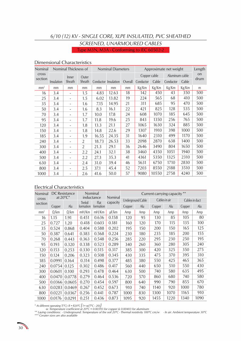
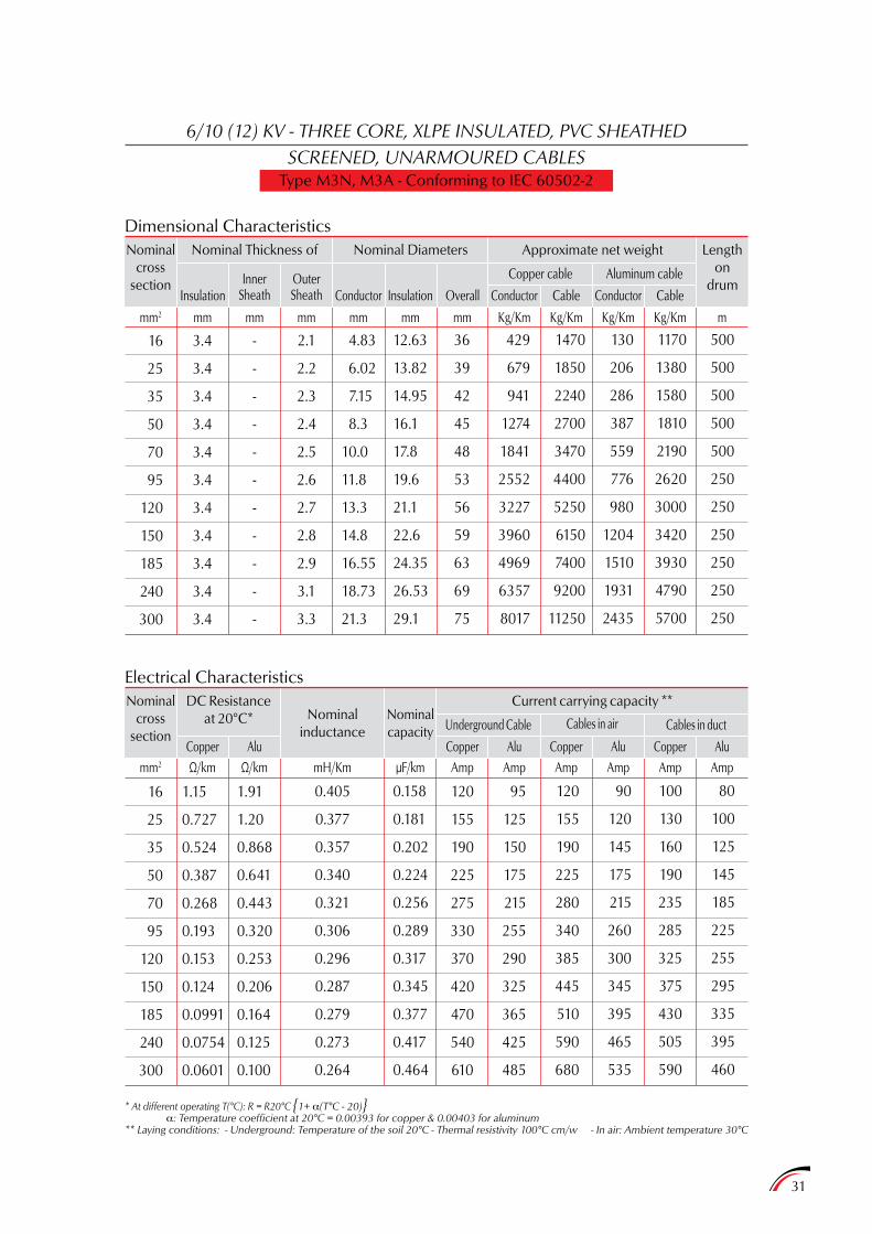
6/10 (12) KV - SINGLE CORE, XLPE INSULATED, PVC SHEATHEDSCREENED, UNARMOURED CABLES
Type M3N, M3A - Conforming to IEC 60502-2
Dimensional Characteristics
Electrical Characteristics
Nominalcross
section
Nominalcross
section
mm2 Ω/km Ω/km mH/Km mH/Km µF/km Amp Amp Amp Amp Amp Amp
Nominal Thickness of
DC Resistanceat 20°C*
Nominalinductance
InsulationInner
Sheath
Copper
OuterSheath
AluTrefoil
formationFlat
formation
Conductor Conductor
Copper cable
Cables in airUnderground CableNominalcapacity
Aluminum cable
Cables in duct
Conductor
CopperCopperCopper
Insulation Overall Cable Cable
AluAluAlu
Nominal Diameters Approximate net weight
Current carrying capacity **
Lengthon
drum
162535507095
120150185240300400500630800
1000
162535507095
120150185240300400500630800
1000
3.43.43.43.43.43.43.43.43.43.43.43.43.43.43.43.4
1.150.7270.5240.3870.2680.1930.1530.1240.09910.07540.06010.04700.03660.02830.02210.0176
----------------
1.911.200.8680.6410.4430.3200.2530.2060.1640.1250.1000.07780.06050.04690.03670.0291
1.51.51.61.61.71.71.81.81.9222.22.22.42.52.6
120160195230285340385430485560630720800910
10001095
4.83 6.02 7.15 8.310.011.813.314.816.5518.7321.324.127.331.037.141.6
95120150180220260300335380440500570640740830920
0.4510.4180.4040.3830.3630.3380.3300.3230.3140.3020.2930.2790.2700.2670.2560.251
0.6360.6030.5880.5680.5480.5230.5150.5080.4980.4860.4780.4640.4540.4520.4410.436
0.1580.1810.2020.2240.2560.2890.3170.3450.3770.4170.4640.5360.5970.6730.7870.873
12.6313.8214.9516.117.819.621.122.624.3526.5329.132.135.339.445.450.0
130170200235295360420475550650740860990
114013001455
18192122242527293133363841465257
85115150185230280325370425510580680790920
10701220
142224311421608843
1065130716402098264634604361563172039080
105135165200250305350395465550635740855
100011651340
450565685825
10701350163019102310287034904350535067508550
10550
80100125155195240275310365430495580670780910
1090
436895
128185256324398499638804
10511325171021882758
350410470535645765885
100011701400165019402310283035104240
500500500500500500500500500500500500500500500500
Kg/Kmmm2 mm mm mm mm mm mm Kg/Km Kg/Km Kg/Km m
* At different operating T(°C): R = R20°C 1+ a(T°C - 20)a: Temperature coefficient at 20°C = 0.00393 for copper & 0.00403 for aluminum
** Laying conditions: - Underground: Temperature of the soil 20°C - Thermal resistivity 100°C cm/w - In air: Ambient temperature 30°C*** Greater sizes are also available
31
6/10 (12) KV - THREE CORE, XLPE INSULATED, PVC SHEATHEDSCREENED, UNARMOURED CABLES
Type M3N, M3A - Conforming to IEC 60502-2
Dimensional Characteristics
Electrical Characteristics
Nominalcross
section
Nominalcross
section
mm2 Ω/km Ω/km mH/Km µF/km Amp Amp Amp Amp Amp Amp
Nominal Thickness of
DC Resistanceat 20°C* Nominal
inductance
InsulationInner
Sheath
Copper
OuterSheath
Alu
Conductor Conductor
Copper cable
Cables in airUnderground CableNominalcapacity
Aluminum cable
Cables in duct
Conductor
CopperCopperCopper
Insulation Overall Cable Cable
AluAluAlu
Nominal Diameters Approximate net weight
Current carrying capacity **
Lengthon
drum
16
25
35
50
70
95
120
150
185
240
300
16
25
35
50
70
95
120
150
185
240
300
3.4
3.4
3.4
3.4
3.4
3.4
3.4
3.4
3.4
3.4
3.4
1.15
0.727
0.524
0.387
0.268
0.193
0.153
0.124
0.0991
0.0754
0.0601
-
-
-
-
-
-
-
-
-
-
-
1.91
1.20
0.868
0.641
0.443
0.320
0.253
0.206
0.164
0.125
0.100
2.1
2.2
2.3
2.4
2.5
2.6
2.7
2.8
2.9
3.1
3.3
120
155
190
225
275
330
370
420
470
540
610
4.83
6.02
7.15
8.3
10.0
11.8
13.3
14.8
16.55
18.73
21.3
95
125
150
175
215
255
290
325
365
425
485
0.405
0.377
0.357
0.340
0.321
0.306
0.296
0.287
0.279
0.273
0.264
0.158
0.181
0.202
0.224
0.256
0.289
0.317
0.345
0.377
0.417
0.464
12.63
13.82
14.95
16.1
17.8
19.6
21.1
22.6
24.35
26.53
29.1
120
155
190
225
280
340
385
445
510
590
680
36
39
42
45
48
53
56
59
63
69
75
90
120
145
175
215
260
300
345
395
465
535
429
679
941
1274
1841
2552
3227
3960
4969
6357
8017
100
130
160
190
235
285
325
375
430
505
590
1470
1850
2240
2700
3470
4400
5250
6150
7400
9200
11250
80
100
125
145
185
225
255
295
335
395
460
130
206
286
387
559
776
980
1204
1510
1931
2435
1170
1380
1580
1810
2190
2620
3000
3420
3930
4790
5700
500
500
500
500
500
250
250
250
250
250
250
Kg/Kmmm2 mm mm mm mm mm mm Kg/Km Kg/Km Kg/Km m
* At different operating T(°C): R = R20°C 1+ a(T°C - 20)a: Temperature coefficient at 20°C = 0.00393 for copper & 0.00403 for aluminum
** Laying conditions: - Underground: Temperature of the soil 20°C - Thermal resistivity 100°C cm/w - In air: Ambient temperature 30°C

32
6/10 (12) KV - THREE CORE, XLPE INSULATED, PVC SHEATHEDSCREENED, DOUBLE STEEL TAPE ARMOURED CABLES
Type M3NB, M3AB - Conforming to IEC 60502-2
Dimensional Characteristics
Electrical Characteristics
Nominalcross
section
Nominalcross
section
mm2 Ω/km Ω/km mH/Km µF/km Amp Amp Amp Amp Amp Amp
Nominal Thickness of
DC Resistanceat 20°C* Nominal
inductance
InsulationInner
Sheath
Copper
OuterSheath
Alu
Conductor Conductor
Copper cable
Cables in airUnderground CableNominalcapacity
Aluminum cable
Cables in duct
Conductor
CopperCopperCopper
Insulation Overall Cable Cable
AluAluAlu
Nominal Diameters Approximate net weight
Current carrying capacity **
Lengthon
drum
16
25
35
50
70
95
120
150
185
240
300
16
25
35
50
70
95
120
150
185
240
300
3.4
3.4
3.4
3.4
3.4
3.4
3.4
3.4
3.4
3.4
3.4
1.15
0.727
0.524
0.387
0.268
0.193
0.153
0.124
0.0991
0.0754
0.0601
1.2
1.3
1.3
1.4
1.5
1.5
1.6
1.6
1.7
1.8
1.9
1.91
1.20
0.868
0.641
0.443
0.320
0.253
0.206
0.164
0.125
0.100
2.3
2.3
2.4
2.5
2.7
2.8
2.9
3.0
3.1
3.3
3.5
120
155
190
225
275
330
370
420
470
540
610
4.83
6.02
7.15
8.3
10.0
11.8
13.3
14.8
16.55
18.73
21.3
95
125
150
175
215
255
290
325
365
425
485
0.445
0.415
0.392
0.374
0.353
0.336
0.325
0.316
0.307
0.300
0.291
0.158
0.181
0.202
0.224
0.256
0.289
0.317
0.345
0.377
0.417
0.464
12.63
13.82
14.95
16.1
17.8
19.6
21.1
22.6
24.35
26.53
29.1
120
155
190
225
280
340
385
445
510
590
680
41
44
47
50
54
58
62
65
69
75
82
90
120
145
175
215
260
300
345
395
465
535
429
679
941
1274
1841
2552
3227
3960
4969
6357
8017
100
130
160
190
235
285
325
375
430
505
590
2310
2750
3190
3740
4650
5650
6650
7650
9000
11000
13250
80
100
125
145
185
225
255
295
335
395
460
130
206
286
387
559
776
980
1204
1510
1931
2435
2010
2280
2540
2860
3360
3890
4390
4890
5550
6600
7650
500
500
500
500
500
250
250
250
250
250
250
Kg/Kmmm2 mm mm mm mm mm mm Kg/Km Kg/Km Kg/Km m
* At different operating T(°C): R = R20°C 1+ a(T°C - 20)a: Temperature coefficient at 20°C = 0.00393 for copper & 0.00403 for aluminum
** Laying conditions: - Underground: Temperature of the soil 20°C - Thermal resistivity 100°C cm/w - In air: Ambient temperature 30°C
33
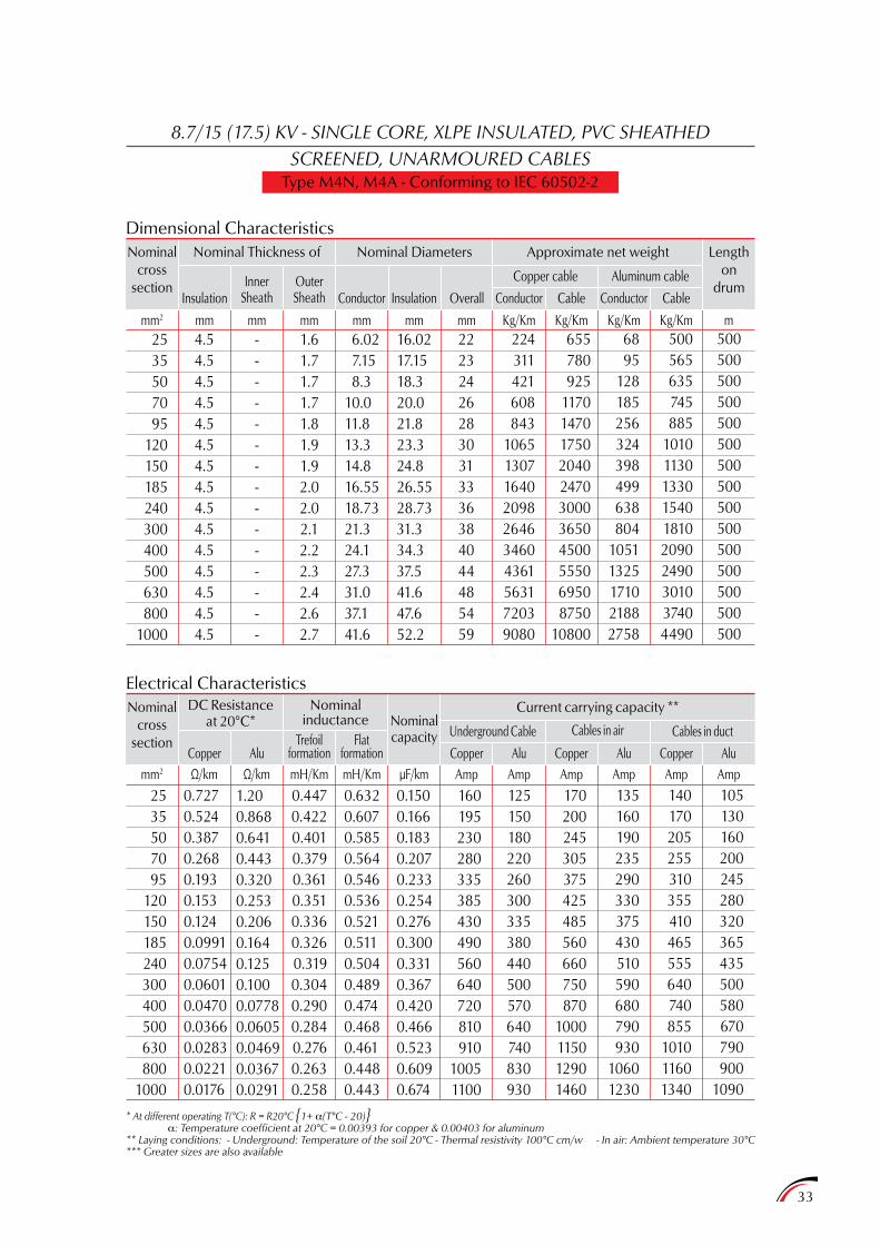
8.7/15 (17.5) KV - SINGLE CORE, XLPE INSULATED, PVC SHEATHEDSCREENED, UNARMOURED CABLES
Type M4N, M4A - Conforming to IEC 60502-2
Dimensional Characteristics
Electrical Characteristics
Nominalcross
section
Nominalcross
section
mm2 Ω/km Ω/km mH/Km mH/Km µF/km Amp Amp Amp Amp Amp Amp
Nominal Thickness of
InsulationInner
Sheath
Copper
OuterSheath
Alu
Conductor Conductor
Copper cable
Cables in airUnderground CableNominalcapacity
Aluminum cable
Cables in duct
Conductor
CopperCopperCopper
Insulation Overall Cable Cable
AluAluAlu
Nominal Diameters Approximate net weight
Current carrying capacity **
Lengthon
drum
2535507095
120150185240300400500630800
1000
2535507095
120150185240300400500630800
1000
4.54.54.54.54.54.54.54.54.54.54.54.54.54.54.5
0.7270.5240.3870.2680.1930.1530.1240.09910.07540.06010.04700.03660.02830.02210.0176
---------------
1.200.8680.6410.4430.3200.2530.2060.1640.1250.1000.07780.06050.04690.03670.0291
1.61.71.71.71.81.91.92.02.02.12.22.32.42.62.7
160195230280335385430490560640720810910
10051100
6.02 7.15 8.310.011.813.314.816.5518.7321.324.127.331.037.141.6
125150180220260300335380440500570640740830930
0.4470.4220.4010.3790.3610.3510.3360.3260.3190.3040.2900.2840.2760.2630.258
0.6320.6070.5850.5640.5460.5360.5210.5110.5040.4890.4740.4680.4610.4480.443
0.1500.1660.1830.2070.2330.2540.2760.3000.3310.3670.4200.4660.5230.6090.674
16.0217.1518.320.021.823.324.826.5528.7331.334.337.541.647.652.2
170200245305375425485560660750870
1000115012901460
222324262830313336384044485459
135160190235290330375430510590680790930
10601230
224311421608843
1065130716402098264634604361563172039080
140170205255310355410465555640740855
101011601340
655780925
11701470175020402470300036504500555069508750
10800
105130160200245280320365435500580670790900
1090
6895
128185256324398499638804
10511325171021882758
500565635745885
1010113013301540181020902490301037404490
500500500500500500500500500500500500500500500
Kg/Kmmm2 mm mm mm mm mm mm Kg/Km Kg/Km Kg/Km m
* At different operating T(°C): R = R20°C 1+ a(T°C - 20)a: Temperature coefficient at 20°C = 0.00393 for copper & 0.00403 for aluminum
** Laying conditions: - Underground: Temperature of the soil 20°C - Thermal resistivity 100°C cm/w - In air: Ambient temperature 30°C*** Greater sizes are also available
DC Resistanceat 20°C*
Nominalinductance
Trefoilformation
Flatformation

34
8.7/15 (17.5) KV - THREE CORE, XLPE INSULATED, PVC SHEATHEDSCREENED, UNARMOURED CABLES
Type M4N, M4A - Conforming to IEC 60502-2
Dimensional Characteristics
Electrical Characteristics
Nominalcross
section
Nominalcross
section
mm2 Ω/km Ω/km mH/Km µF/km Amp Amp Amp Amp Amp Amp
Nominal Thickness of
Nominalinductance
InsulationInner
SheathOuterSheath Conductor Conductor
Copper cable
Cables in airUnderground CableNominalcapacity
Aluminum cable
Cables in duct
Conductor
CopperCopperCopper
Insulation Overall Cable Cable
AluAluAlu
Nominal Diameters Approximate net weight
Current carrying capacity **
Lengthon
drum
25
35
50
70
95
120
150
185
240
300
25
35
50
70
95
120
150
185
240
300
4.5
4.5
4.5
4.5
4.5
4.5
4.5
4.5
4.5
4.5
0.727
0.524
0.387
0.268
0.193
0.153
0.124
0.0991
0.0754
0.0601
-
-
-
-
-
-
-
-
-
-
1.20
0.868
0.641
0.443
0.320
0.253
0.206
0.164
0.125
0.100
2.4
2.4
2.5
2.7
2.8
2.9
3.0
3.1
3.3
3.4
155
190
225
270
330
370
415
465
540
620
6.02
7.15
8.3
10.0
11.8
13.3
14.8
16.55
18.73
21.3
115
145
175
210
255
290
320
360
420
490
0.404
0.381
0.364
0.343
0.326
0.314
0.304
0.299
0.287
0.278
0.150
0.166
0.183
0.207
0.233
0.254
0.276
0.300
0.331
0.367
16.02
17.15
18.3
20.0
21.8
23.3
24.8
26.55
28.73
31.3
160
195
230
280
345
395
450
510
600
685
44
47
50
54
58
61
65
69
75
80
120
150
175
220
265
305
345
395
470
535
679
941
1274
1841
2552
3227
3960
4969
6357
8017
135
165
195
235
285
330
375
430
510
585
2180
2570
3060
3870
4840
5700
6650
8000
9800
11800
100
125
150
185
225
260
295
335
400
455
206
286
387
559
776
980
1204
1510
1931
2435
1720
1920
2170
2590
3060
3470
3900
4540
5350
6200
500
500
500
250
250
250
250
250
250
250
Kg/Kmmm2 mm mm mm mm mm mm Kg/Km Kg/Km Kg/Km m
* At different operating T(°C): R = R20°C 1+ a(T°C - 20)a: Temperature coefficient at 20°C = 0.00393 for copper & 0.00403 for aluminum
** Laying conditions: - Underground: Temperature of the soil 20°C - Thermal resistivity 100°C cm/w - In air: Ambient temperature 30°C
AluCopper
DC Resistanceat 20°C*
35
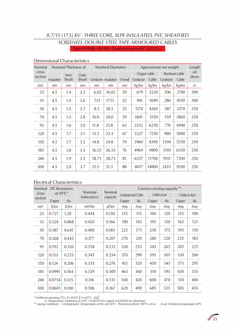
8.7/15 (17.5) KV - THREE CORE, XLPE INSULATED, PVC SHEATHEDSCREENED, DOUBLE STEEL TAPE ARMOURED CABLES
Type M4NB, M4AB - Conforming to IEC 60502-2
Dimensional Characteristics
Electrical Characteristics
Nominalcross
section
Nominalcross
section
mm2 Ω/km Ω/km mH/Km µF/km Amp Amp Amp Amp Amp Amp
Nominal Thickness of
DC Resistanceat 20°C* Nominal
inductance
InsulationInner
Sheath
Copper
OuterSheath
Alu
Conductor Conductor
Copper cable
Cables in airUnderground CableNominalcapacity
Aluminum cable
Cables in duct
Conductor
CopperCopperCopper
Insulation Overall Cable Cable
AluAluAlu
Nominal Diameters Approximate net weight
Current carrying capacity **
Lengthon
drum
25
35
50
70
95
120
150
185
240
300
25
35
50
70
95
120
150
185
240
300
4.5
4.5
4.5
4.5
4.5
4.5
4.5
4.5
4.5
4.5
0.727
0.524
0.387
0.268
0.193
0.153
0.124
0.0991
0.0754
0.0601
1.4
1.4
1.5
1.5
1.6
1.7
1.7
1.8
1.9
2.0
1.20
0.868
0.641
0.443
0.320
0.253
0.206
0.164
0.125
0.100
2.5
2.6
2.7
2.8
3.0
3.1
3.2
3.3
3.5
3.7
155
190
225
270
330
370
415
465
540
620
6.02
7.15
8.3
10.0
11.8
13.3
14.8
16.55
18.73
21.3
115
145
175
210
255
290
320
360
420
490
0.444
0.420
0.400
0.377
0.358
0.345
0.335
0.329
0.316
0.306
0.150
0.166
0.183
0.207
0.233
0.254
0.276
0.300
0.331
0.367
16.02
17.15
18.3
20.0
21.8
23.3
24.8
26.55
28.73
31.3
160
195
230
280
345
395
450
510
600
685
50
52
55
59
63
67
70
76
81
88
120
150
175
220
265
305
345
395
470
535
679
941
1274
1841
2552
3227
3960
4969
6357
8017
135
165
195
235
285
330
375
430
510
585
3220
3690
4260
5150
6250
7250
8300
9800
11700
14800
100
125
150
185
225
260
295
335
400
455
206
286
387
559
776
980
1204
1510
1931
2435
2740
3030
3370
3860
4490
5000
5550
6350
7300
9200
500
500
250
250
250
250
250
250
250
250
Kg/Kmmm2 mm mm mm mm mm mm Kg/Km Kg/Km Kg/Km m
* At different operating T(°C): R = R20°C 1+ a(T°C - 20)a: Temperature coefficient at 20°C = 0.00393 for copper & 0.00403 for aluminum
** Laying conditions: - Underground: Temperature of the soil 20°C - Thermal resistivity 100°C cm/w - In air: Ambient temperature 30°C
36
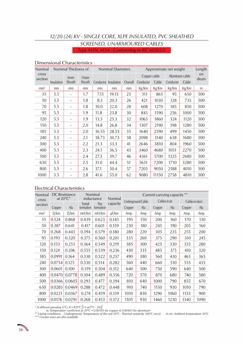
12/20 (24) KV - SINGLE CORE, XLPE INSULATED, PVC SHEATHEDSCREENED, UNARMOURED CABLES
Type M5N, M5A - Conforming to IEC 60502-2
Dimensional Characteristics
Electrical Characteristics
Nominalcross
section
Nominalcross
section
mm2 Ω/km Ω/km mH/Km mH/Km µF/km Amp Amp Amp Amp Amp Amp
Nominal Thickness of
InsulationInner
SheathOuterSheath Conductor Conductor
Copper cable
Cables in airUnderground CableNominalcapacity
Aluminum cable
Cables in duct
Conductor
CopperCopperCopper
Insulation Overall Cable Cable
AluAluAlu
Nominal Diameters Approximate net weight
Current carrying capacity **
Lengthon
drum
35507095
120150185240300400500630800
1000
35507095
120150185240300400500630800
1000
5.55.55.55.55.55.55.55.55.55.55.55.55.55.5
0.5240.3870.2680.1930.1530.1240.09910.07540.06010.04700.03660.02830.02210.0176
--------------
0.8680.6410.4430.3200.2530.2060.1640.1250.1000.07780.06050.04690.03670.0291
1.71.81.81.91.92.02.02.12.22.32.42.52.62.8
195230280335385430490560640720810910
10101105
7.15 8.310.011.813.314.816.5518.7321.324.127.331.037.141.6
150180220260300335380440500570640740830930
0.4390.4170.3940.3750.3640.3550.3380.3300.3190.3040.2930.2880.2740.268
0.6230.6010.5790.5600.5490.5390.5220.5140.5040.4890.4770.4720.4590.453
0.1450.1590.1800.2010.2190.2360.2570.2820.3120.3560.3940.4480.5190.572
19.1520.322.023.825.326.828.5530.7333.336.539.744.450.455.0
200245305375425485560660750870
1000115012901460
2526283032343538414346515762
160190235290330375430510590680790930
10601230
311421608843
1065130716402098264634604361563172039080
170205255310355410465555640740855
101011551340
865103012701590186021902590314038104680570072009050
11150
130160200245280320365435500580670790900
1090
95128185256324398499638804
10511325171021882758
650735850
10001120128014501680196022702680328040104810
500500500500500500500500500500500500500500
Kg/Kmmm2 mm mm mm mm mm mm Kg/Km Kg/Km Kg/Km m
* At different operating T(°C): R = R20°C 1+ a(T°C - 20)a: Temperature coefficient at 20°C = 0.00393 for copper & 0.00403 for aluminum
** Laying conditions: - Underground: Temperature of the soil 20°C - Thermal resistivity 100°C cm/w - In air: Ambient temperature 30°C*** Greater sizes are also available
DC Resistanceat 20°C*
Nominalinductance
Copper AluTrefoil
formationFlat
formation

37
12/20 (24) KV - THREE CORE, XLPE INSULATED, PVC SHEATHEDSCREENED, UNARMOURED CABLES
Type M5N, M5A - Conforming to IEC 60502-2
Dimensional Characteristics
Electrical Characteristics
Nominalcross
section
Nominalcross
section
mm2 Ω/km Ω/km mH/Km µF/km Amp Amp Amp Amp Amp Amp
Nominal Thickness of
Nominalinductance
InsulationInner
SheathOuterSheath Conductor Conductor
Copper cable
Cables in airUnderground CableNominalcapacity
Aluminum cable
Cables in duct
Conductor
CopperCopperCopper
Insulation Overall Cable Cable
AluAluAlu
Nominal Diameters Approximate net weight
Current carrying capacity **
Lengthon
drum
35
50
70
95
120
150
185
240
300
35
50
70
95
120
150
185
240
300
5.5
5.5
5.5
5.5
5.5
5.5
5.5
5.5
5.5
0.524
0.387
0.268
0.193
0.153
0.124
0.0991
0.0754
0.0601
-
-
-
-
-
-
-
-
-
0.868
0.641
0.443
0.320
0.253
0.206
0.164
0.125
0.100
2.6
2.7
2.8
2.9
3.0
3.1
3.2
3.4
3.6
190
225
270
330
370
415
465
540
620
7.15
8.3
10.0
11.8
13.3
14.8
16.55
18.73
21.3
145
175
210
255
290
320
360
420
490
0.402
0.383
0.360
0.342
0.330
0.322
0.311
0.300
0.290
0.145
0.159
0.180
0.201
0.219
0.236
0.257
0.282
0.312
19.15
20.3
22.0
23.8
25.3
26.8
28.55
30.73
33.3
195
230
280
345
395
450
510
600
685
52
54
58
62
66
70
74
79
85
150
175
220
265
305
345
395
470
535
941
1274
1841
2552
3227
3960
4969
6357
8017
165
195
235
285
330
375
430
510
585
2900
3440
4250
5200
6100
7200
8450
10300
12400
125
150
185
225
260
295
335
400
455
286
387
559
776
980
1204
1510
1931
2435
2250
2550
2960
3440
3860
4430
4950
5850
6800
500
250
250
250
250
250
250
250
250
Kg/Kmmm2 mm mm mm mm mm mm Kg/Km Kg/Km Kg/Km m
* At different operating T(°C): R = R20°C 1+ a(T°C - 20)a: Temperature coefficient at 20°C = 0.00393 for copper & 0.00403 for aluminum
** Laying conditions: - Underground: Temperature of the soil 20°C - Thermal resistivity 100°C cm/w - In air: Ambient temperature 30°C
DC Resistanceat 20°C*
Copper Alu
38
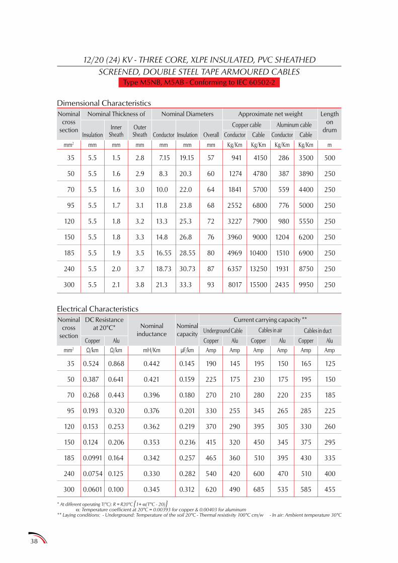
12/20 (24) KV - THREE CORE, XLPE INSULATED, PVC SHEATHEDSCREENED, DOUBLE STEEL TAPE ARMOURED CABLES
Type M5NB, M5AB - Conforming to IEC 60502-2
Dimensional Characteristics
Electrical Characteristics
Nominalcross
section
Nominalcross
section
mm2 Ω/km Ω/km mH/Km µF/km Amp Amp Amp Amp Amp Amp
Nominal Thickness of
Nominalinductance
InsulationInner
SheathOuterSheath Conductor Conductor
Copper cable
Cables in airUnderground CableNominalcapacity
Aluminum cable
Cables in duct
Conductor
CopperCopperCopper
Insulation Overall Cable Cable
AluAluAlu
Nominal Diameters Approximate net weight
Current carrying capacity **
Lengthon
drum
35
50
70
95
120
150
185
240
300
35
50
70
95
120
150
185
240
300
5.5
5.5
5.5
5.5
5.5
5.5
5.5
5.5
5.5
0.524
0.387
0.268
0.193
0.153
0.124
0.0991
0.0754
0.0601
1.5
1.6
1.6
1.7
1.8
1.8
1.9
2.0
2.1
0.868
0.641
0.443
0.320
0.253
0.206
0.164
0.125
0.100
2.8
2.9
3.0
3.1
3.2
3.3
3.5
3.7
3.8
190
225
270
330
370
415
465
540
620
7.15
8.3
10.0
11.8
13.3
14.8
16.55
18.73
21.3
145
175
210
255
290
320
360
420
490
0.442
0.421
0.396
0.376
0.362
0.353
0.342
0.330
0.345
0.145
0.159
0.180
0.201
0.219
0.236
0.257
0.282
0.312
19.15
20.3
22.0
23.8
25.3
26.8
28.55
30.73
33.3
195
230
280
345
395
450
510
600
685
57
60
64
68
72
76
80
87
93
150
175
220
265
305
345
395
470
535
941
1274
1841
2552
3227
3960
4969
6357
8017
165
195
235
285
330
375
430
510
585
4150
4780
5700
6800
7900
9000
10400
13250
15500
125
150
185
225
260
295
335
400
455
286
387
559
776
980
1204
1510
1931
2435
3500
3890
4400
5000
5550
6200
6900
8750
9950
500
250
250
250
250
250
250
250
250
Kg/Kmmm2 mm mm mm mm mm mm Kg/Km Kg/Km Kg/Km m
* At different operating T(°C): R = R20°C 1+ a(T°C - 20)a: Temperature coefficient at 20°C = 0.00393 for copper & 0.00403 for aluminum
** Laying conditions: - Underground: Temperature of the soil 20°C - Thermal resistivity 100°C cm/w - In air: Ambient temperature 30°C
AluCopper
DC Resistanceat 20°C*
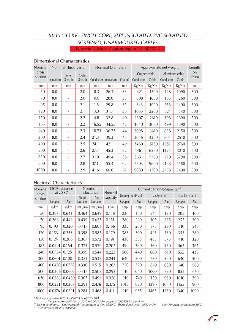
39
18/30 (36) KV - SINGLE CORE, XLPE INSULATED, PVC SHEATHEDSCREENED, UNARMOURED CABLES
Type M6N, M6A - Conforming to IEC 60502-2
Dimensional Characteristics
Electrical Characteristics
Nominalcross
section
Nominalcross
section
mm2 Ω/km Ω/km mH/Km mH/Km µF/km Amp Amp Amp Amp Amp Amp
Nominal Thickness of
InsulationInner
SheathOuterSheath Conductor Conductor
Copper cable
Cables in airUnderground CableNominalcapacity
Aluminum cable
Cables in duct
Conductor
CopperCopperCopper
Insulation Overall Cable Cable
AluAluAlu
Nominal Diameters Approximate net weight
Current carrying capacity **
Lengthon
drum
50
70
95
120
150
185
240
300
400
500
630
800
1000
50
70
95
120
150
185
240
300
400
500
630
800
1000
8.0
8.0
8.0
8.0
8.0
8.0
8.0
8.0
8.0
8.0
8.0
8.0
8.0
0.387
0.268
0.193
0.153
0.124
0.0991
0.0754
0.0601
0.0470
0.0366
0.0283
0.0221
0.0176
-
-
-
-
-
-
-
-
-
-
-
-
-
0.641
0.443
0.320
0.253
0.206
0.164
0.125
0.100
0.0778
0.0605
0.0469
0.0367
0.0291
2.0
2.0
2.1
2.1
2.2
2.2
2.3
2.4
2.5
2.6
2.7
2.8
2.9
230
280
335
385
430
490
560
640
720
810
910
1015
1110
8.3
10.0
11.8
13.3
14.8
16.55
18.73
21.3
24.1
27.3
31.0
37.1
41.6
180
220
260
300
335
380
440
500
570
640
740
830
935
0.464
0.439
0.417
0.398
0.387
0.375
0.359
0.351
0.330
0.317
0.307
0.291
0.284
0.649
0.623
0.601
0.583
0.572
0.559
0.544
0.535
0.515
0.502
0.491
0.476
0.468
0.136
0.151
0.166
0.179
0.191
0.205
0.223
0.244
0.267
0.293
0.326
0.375
0.411
26.3
28.0
29.8
31.3
32.8
34.55
36.73
39.3
42.1
45.3
49.4
55.4
60.0
245
305
375
425
485
560
660
750
870
1000
1150
1290
1465
33
35
37
38
40
42
44
48
49
52
56
62
67
190
235
290
330
375
430
510
590
680
790
930
1060
1230
421
608
843
1065
1307
1640
2098
2646
3460
4361
5631
7203
9080
205
255
310
355
410
465
555
640
740
855
1010
1155
1340
1390
1660
1990
2280
2610
3030
3610
4350
5150
6250
7700
9600
11700
160
200
245
280
320
365
435
500
580
670
790
900
1090
128
185
256
324
398
499
638
804
1051
1325
1710
2188
2758
1090
1260
1400
1540
1690
1890
2150
2510
2760
3210
3790
4580
5400
500
500
500
500
500
500
500
500
500
500
500
500
500
Kg/Kmmm2 mm mm mm mm mm mm Kg/Km Kg/Km Kg/Km m
* At different operating T(°C): R = R20°C 1+ a(T°C - 20)a: Temperature coefficient at 20°C = 0.00393 for copper & 0.00403 for aluminum
** Laying conditions: - Underground: Temperature of the soil 20°C - Thermal resistivity 100°C cm/w - In air: Ambient temperature 30°C*** Greater sizes are also available
Copper Alu
DC Resistanceat 20°C*
Nominalinductance
Trefoilformation
Flatformation

40
18/30 (36) KV - THREE CORE, XLPE INSULATED, PVC SHEATHEDSCREENED, UNARMOURED CABLES
Type M6N, M6A - Conforming to IEC 60502-2
Dimensional Characteristics
Electrical Characteristics
Nominalcross
section
Nominalcross
section
mm2 Ω/km Ω/km mH/Km µF/km Amp Amp Amp Amp Amp Amp
Nominal Thickness of
Nominalinductance
InsulationInner
SheathOuterSheath Conductor Conductor
Copper cable
Cables in airUnderground CableNominalcapacity
Aluminum cable
Cables in duct
Conductor
CopperCopperCopper
Insulation Overall Cable Cable
AluAluAlu
Nominal Diameters Approximate net weight
Current carrying capacity **
Lengthon
drum
50
70
95
120
150
185
240
300
50
70
95
120
150
185
240
300
8.0
8.0
8.0
8.0
8.0
8.0
8.0
8.0
0.387
0.268
0.193
0.153
0.124
0.0991
0.0754
0.0601
-
-
-
-
-
-
-
-
0.641
0.443
0.320
0.253
0.206
0.164
0.125
0.100
3.1
3.2
3.3
3.4
3.5
3.6
3.8
4.0
225
270
330
370
415
465
540
620
8.3
10.0
11.8
13.3
14.8
16.55
18.73
21.3
175
210
255
290
320
360
420
490
0.435
0.409
0.388
0.373
0.361
0.348
0.335
0.324
0.136
0.151
0.166
0.179
0.191
0.205
0.223
0.244
26.3
28.0
29.8
31.3
32.8
34.55
36.73
39.3
230
280
345
395
450
510
600
685
69
73
77
80
84
88
93
100
175
220
265
305
345
395
470
535
1274
1841
2552
3227
3960
4969
6357
8017
195
235
285
330
375
430
510
585
4730
5600
6700
7650
8750
10150
12050
14400
150
185
225
260
295
335
400
455
387
559
776
980
1204
1510
1931
2435
3840
4320
4900
5400
5950
6300
7600
8850
250
250
250
250
250
250
250
250
Kg/Kmmm2 mm mm mm mm mm mm Kg/Km Kg/Km Kg/Km m
* At different operating T(°C): R = R20°C 1+ a(T°C - 20)a: Temperature coefficient at 20°C = 0.00393 for copper & 0.00403 for aluminum
** Laying conditions: - Underground: Temperature of the soil 20°C - Thermal resistivity 100°C cm/w - In air: Ambient temperature 30°C
AluCopper
DC Resistanceat 20°C*
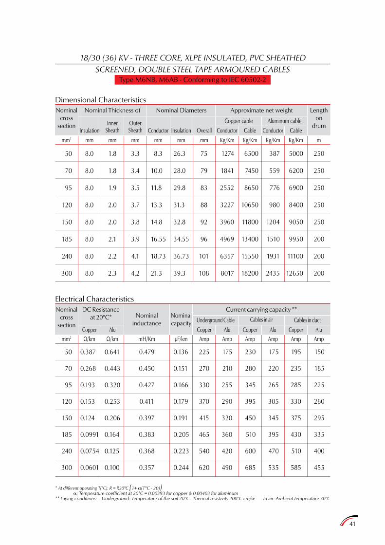
41
18/30 (36) KV - THREE CORE, XLPE INSULATED, PVC SHEATHEDSCREENED, DOUBLE STEEL TAPE ARMOURED CABLES
Type M6NB, M6AB - Conforming to IEC 60502-2
Dimensional Characteristics
Electrical Characteristics
Nominalcross
section
Nominalcross
section
mm2 Ω/km Ω/km mH/Km µF/km Amp Amp Amp Amp Amp Amp
Nominal Thickness of
Nominalinductance
InsulationInner
SheathOuterSheath Conductor Conductor
Copper cable
Cables in airUnderground CableNominalcapacity
Aluminum cable
Cables in duct
Conductor
CopperCopperCopper
Insulation Overall Cable Cable
AluAluAlu
Nominal Diameters Approximate net weight
Current carrying capacity **
Lengthon
drum
50
70
95
120
150
185
240
300
50
70
95
120
150
185
240
300
8.0
8.0
8.0
8.0
8.0
8.0
8.0
8.0
0.387
0.268
0.193
0.153
0.124
0.0991
0.0754
0.0601
1.8
1.8
1.9
2.0
2.0
2.1
2.2
2.3
0.641
0.443
0.320
0.253
0.206
0.164
0.125
0.100
3.3
3.4
3.5
3.7
3.8
3.9
4.1
4.2
225
270
330
370
415
465
540
620
8.3
10.0
11.8
13.3
14.8
16.55
18.73
21.3
175
210
255
290
320
360
420
490
0.479
0.450
0.427
0.411
0.397
0.383
0.368
0.357
0.136
0.151
0.166
0.179
0.191
0.205
0.223
0.244
26.3
28.0
29.8
31.3
32.8
34.55
36.73
39.3
230
280
345
395
450
510
600
685
75
79
83
88
92
96
101
108
175
220
265
305
345
395
470
535
1274
1841
2552
3227
3960
4969
6357
8017
195
235
285
330
375
430
510
585
6500
7450
8650
10650
11800
13400
15550
18200
150
185
225
260
295
335
400
455
387
559
776
980
1204
1510
1931
2435
5000
6200
6900
8400
9050
9950
11100
12650
250
250
250
250
250
200
200
200
Kg/Kmmm2 mm mm mm mm mm mm Kg/Km Kg/Km Kg/Km m
* At different operating T(°C): R = R20°C 1+ a(T°C - 20)a: Temperature coefficient at 20°C = 0.00393 for copper & 0.00403 for aluminum
** Laying conditions: - Underground: Temperature of the soil 20°C - Thermal resistivity 100°C cm/w - In air: Ambient temperature 30°C
DC Resistanceat 20°C*
Copper Alu
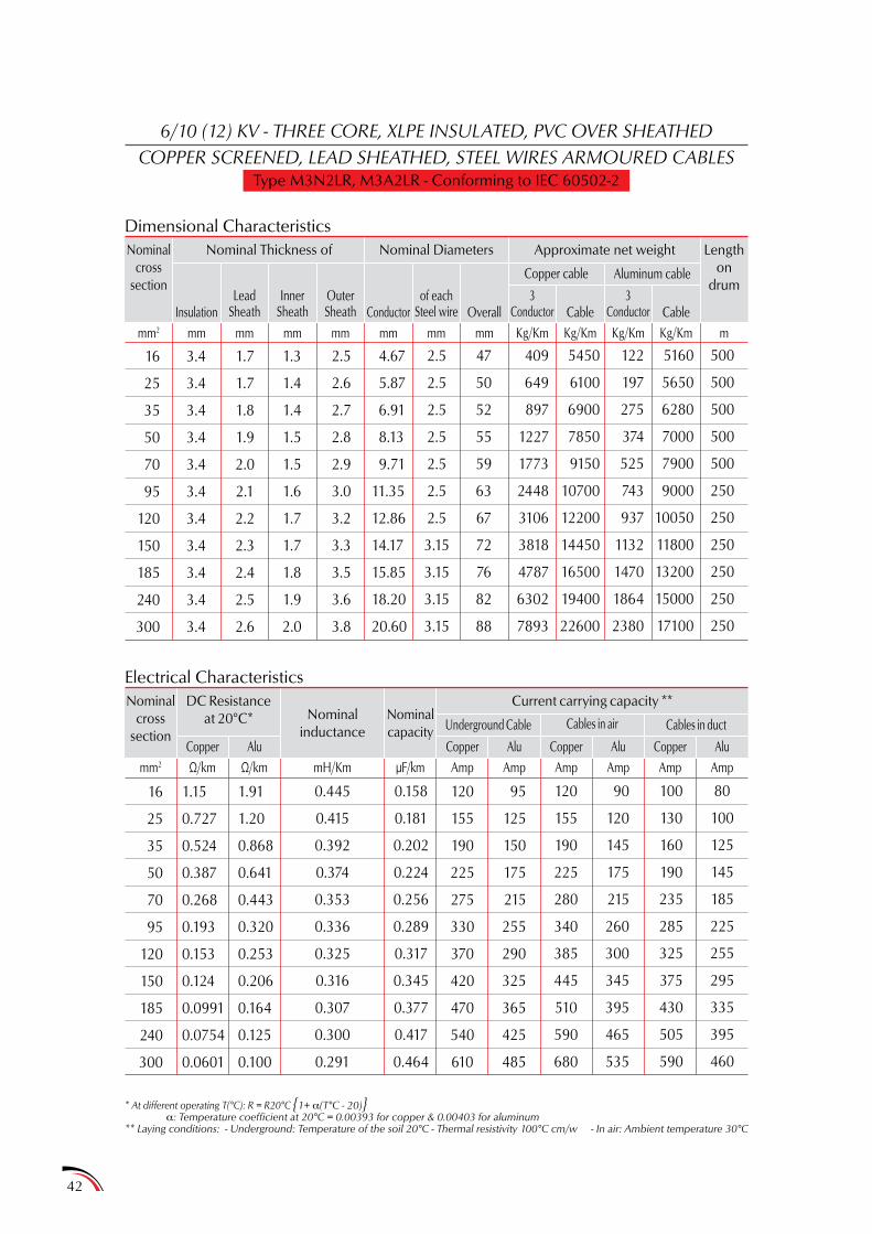
42
6/10 (12) KV - THREE CORE, XLPE INSULATED, PVC OVER SHEATHEDCOPPER SCREENED, LEAD SHEATHED, STEEL WIRES ARMOURED CABLES
Type M3N2LR, M3A2LR - Conforming to IEC 60502-2
Dimensional Characteristics
Electrical Characteristics
Nominalcross
section
Nominalcross
section
mm2 Ω/km Ω/km mH/Km µF/km Amp Amp Amp Amp Amp Amp
Nominal Thickness of
Nominalinductance
InsulationLead
SheathInner
SheathOuterSheath Conductor
3Conductor
3Conductor
Copper cable
Cables in airUnderground CableNominalcapacity
Aluminum cable
Cables in duct
CopperCopperCopper
of eachSteel wire Overall Cable Cable
AluAluAlu
Nominal Diameters Approximate net weight
Current carrying capacity **
Lengthon
drum
16
25
35
50
70
95
120
150
185
240
300
16
25
35
50
70
95
120
150
185
240
300
3.4
3.4
3.4
3.4
3.4
3.4
3.4
3.4
3.4
3.4
3.4
1.7
1.7
1.8
1.9
2.0
2.1
2.2
2.3
2.4
2.5
2.6
1.15
0.727
0.524
0.387
0.268
0.193
0.153
0.124
0.0991
0.0754
0.0601
1.3
1.4
1.4
1.5
1.5
1.6
1.7
1.7
1.8
1.9
2.0
1.91
1.20
0.868
0.641
0.443
0.320
0.253
0.206
0.164
0.125
0.100
2.5
2.6
2.7
2.8
2.9
3.0
3.2
3.3
3.5
3.6
3.8
120
155
190
225
275
330
370
420
470
540
610
4.67
5.87
6.91
8.13
9.71
11.35
12.86
14.17
15.85
18.20
20.60
95
125
150
175
215
255
290
325
365
425
485
0.445
0.415
0.392
0.374
0.353
0.336
0.325
0.316
0.307
0.300
0.291
0.158
0.181
0.202
0.224
0.256
0.289
0.317
0.345
0.377
0.417
0.464
2.5
2.5
2.5
2.5
2.5
2.5
2.5
3.15
3.15
3.15
3.15
120
155
190
225
280
340
385
445
510
590
680
47
50
52
55
59
63
67
72
76
82
88
90
120
145
175
215
260
300
345
395
465
535
409
649
897
1227
1773
2448
3106
3818
4787
6302
7893
100
130
160
190
235
285
325
375
430
505
590
5450
6100
6900
7850
9150
10700
12200
14450
16500
19400
22600
80
100
125
145
185
225
255
295
335
395
460
122
197
275
374
525
743
937
1132
1470
1864
2380
5160
5650
6280
7000
7900
9000
10050
11800
13200
15000
17100
500
500
500
500
500
250
250
250
250
250
250
Kg/Kmmm2 mm mm mm mm mm mm mm Kg/Km Kg/Km Kg/Km m
* At different operating T(°C): R = R20°C 1+ a(T°C - 20)a: Temperature coefficient at 20°C = 0.00393 for copper & 0.00403 for aluminum
** Laying conditions: - Underground: Temperature of the soil 20°C - Thermal resistivity 100°C cm/w - In air: Ambient temperature 30°C
AluCopper
DC Resistanceat 20°C*
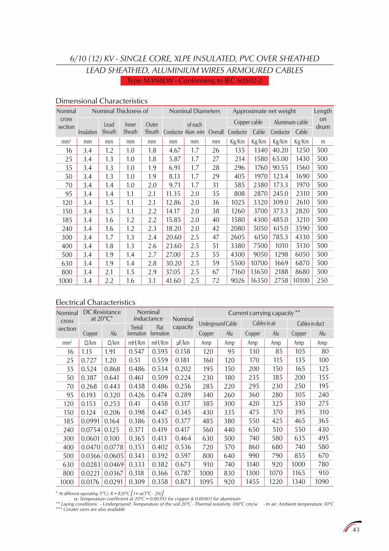
43
6/10 (12) KV - SINGLE CORE, XLPE INSULATED, PVC OVER SHEATHEDLEAD SHEATHED, ALUMINIUM WIRES ARMOURED CABLES
Type M3N8LW - Conforming to IEC 60502-2
Dimensional CharacteristicsNominal
crosssection
Nominal Thickness of
InsulationLead
SheathInner
SheathOuterSheath Conductor Conductor Conductor
Copper cable Aluminum cableof eachAlum. wire Overall Cable Cable
Nominal Diameters Approximate net weight Lengthon
drum
162535507095
120150185240300400500630800
1000
3.43.43.43.43.43.43.43.43.43.43.43.43.43.43.43.4
1.21.31.31.31.41.41.51.51.61.61.71.81.91.92.12.2
1.01.01.01.01.01.11.11.11.21.21.31.31.41.41.51.6
1.81.81.91.92.02.12.12.22.22.32.42.62.72.82.93.1
4.67 5.87 6.91 8.13 9.7111.3512.8614.1715.8518.2020.6023.6027.0030.2037.0541.60
1.71.71.71.71.72.02.02.02.02.02.52.52.52.52.52.5
26272829313536384042475155596772
135214296405585808
1025126015802080260533804300550071609026
1340158017601970238028703320370043005050615075009050
107001365016350
40.2065.0090.55123.4173.3245.0309.0373.3485.0615.0785.310101298166921882758
125014301560169019702310261028203210359043305130605068708680
10100
500500500500500500500500500500500500500500500250
Kg/Kmmm2 mm mm mm mm mm mm mm Kg/Km Kg/Km Kg/Km m
Electrical CharacteristicsNominal
crosssection
mm2 Ω/km Ω/km mH/Km mH/Km µF/km Amp Amp Amp Amp Amp Amp
Cables in airUnderground CableNominalcapacity Cables in duct
CopperCopperCopper AluAluAlu
Current carrying capacity **
162535507095
120150185240300400500630800
1000
1.150.7270.5240.3870.2680.1930.1530.1240.09910.07540.06010.04700.03660.02830.02210.0176
1.911.200.8680.6410.4430.3200.2530.2060.1640.1250.1000.07780.06050.04690.03670.0291
120160195230285340385430485560630720800910
10001095
95120150180220260300335380440500570640740830920
0.5470.510.4860.4610.4380.4260.410.3980.3860.3710.3650.3530.3430.3330.3180.309
0.5950.5590.5340.5090.4860.4740.4580.4470.4350.4190.4130.4020.3920.3820.3660.358
0.1580.1810.2020.2240.2560.2890.3170.3450.3770.4170.4640.5360.5970.6730.7870.873
130170200235295360420475550650740860990
114013001455
85115150185230280325370425510580680790920
10701220
105135165200250305350395465550635740855
100011651340
80100125155195240275310365430495580670780910
1090
* At different operating T(°C): R = R20°C 1+ a(T°C - 20)a: Temperature coefficient at 20°C = 0.00393 for copper & 0.00403 for aluminum
** Laying conditions: - Underground: Temperature of the soil 20°C - Thermal resistivity 100°C cm/w - In air: Ambient temperature 30°C*** Greater sizes are also available
Copper Alu
DC Resistanceat 20°C*
Nominalinductance
Trefoilformation
Flatformation
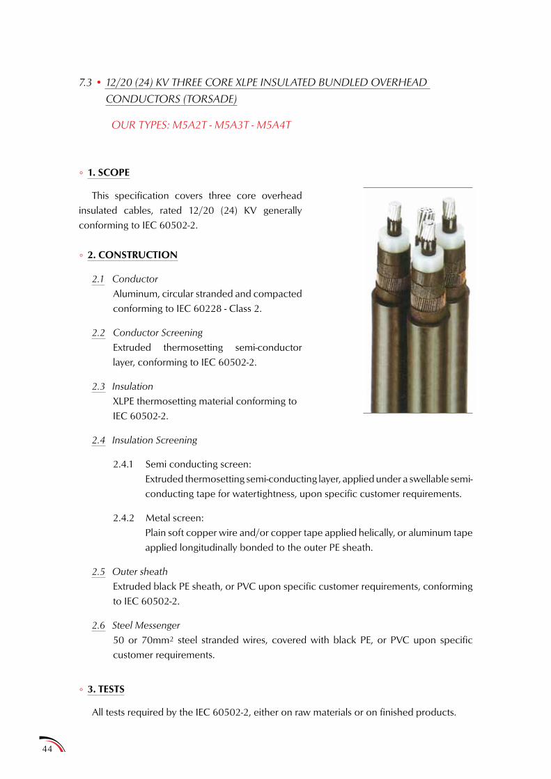
44
7.3 • 12/20 (24) KV THREE CORE XLPE INSULATED BUNDLED OVERHEAD
CONDUCTORS (TORSADE)
OUR TYPES: M5A2T - M5A3T - M5A4T
° 1. SCOPE
This specification covers three core overhead insulated cables, rated 12/20 (24) KV generally conforming to IEC 60502-2.
° 2. CONSTRUCTION
2.1 Conductor
Aluminum, circular stranded and compacted conforming to IEC 60228 - Class 2.
2.2 Conductor Screening
Extruded thermosetting semi-conductor layer, conforming to IEC 60502-2.
2.3 Insulation
XLPE thermosetting material conforming to IEC 60502-2.
2.4 Insulation Screening
2.4.1 Semi conducting screen:Extruded thermosetting semi-conducting layer, applied under a swellable semi-conducting tape for watertightness, upon specific customer requirements.
2.4.2 Metal screen:Plain soft copper wire and/or copper tape applied helically, or aluminum tape applied longitudinally bonded to the outer PE sheath.
2.5 Outer sheath
Extruded black PE sheath, or PVC upon specific customer requirements, conforming to IEC 60502-2.
2.6 Steel Messenger
50 or 70mm2 steel stranded wires, covered with black PE, or PVC upon specific customer requirements.
° 3. TESTS
All tests required by the IEC 60502-2, either on raw materials or on finished products.
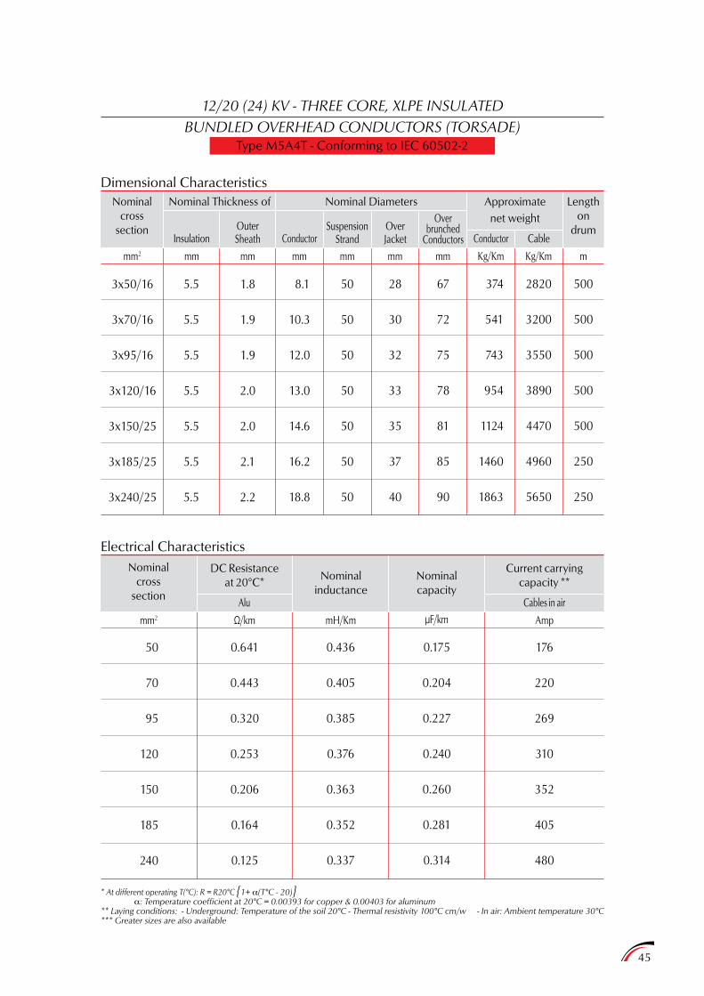
45
12/20 (24) KV - THREE CORE, XLPE INSULATEDBUNDLED OVERHEAD CONDUCTORS (TORSADE)
Type M5A4T - Conforming to IEC 60502-2
Dimensional Characteristics
Electrical Characteristics
Nominalcross
section
Nominalcross
section
mm2 Ω/km mH/Km µF/km Amp
Nominal Thickness of
DC Resistanceat 20°C* Nominal
inductance
InsulationOuterSheath
Alu
OverJacket
Cables in air
Nominalcapacity
ConductorConductorSuspension
Strand
Overbrunched
Conductors Cable
Nominal Diameters Approximatenet weight
Current carryingcapacity **
Lengthon
drum
50
70
95
120
150
185
240
3x50/16
3x70/16
3x95/16
3x120/16
3x150/25
3x185/25
3x240/25
1.8
1.9
1.9
2.0
2.0
2.1
2.2
5.5
5.5
5.5
5.5
5.5
5.5
5.5
0.641
0.443
0.320
0.253
0.206
0.164
0.125
8.1
10.3
12.0
13.0
14.6
16.2
18.8
176
220
269
310
352
405
480
50
50
50
50
50
50
50
0.436
0.405
0.385
0.376
0.363
0.352
0.337
0.175
0.204
0.227
0.240
0.260
0.281
0.314
28
30
32
33
35
37
40
67
72
75
78
81
85
90
374
541
743
954
1124
1460
1863
2820
3200
3550
3890
4470
4960
5650
500
500
500
500
500
250
250
mm2 mm mm mm mm mm mm Kg/Km Kg/Km m
* At different operating T(°C): R = R20°C 1+ a(T°C - 20)a: Temperature coefficient at 20°C = 0.00393 for copper & 0.00403 for aluminum
** Laying conditions: - Underground: Temperature of the soil 20°C - Thermal resistivity 100°C cm/w - In air: Ambient temperature 30°C*** Greater sizes are also available
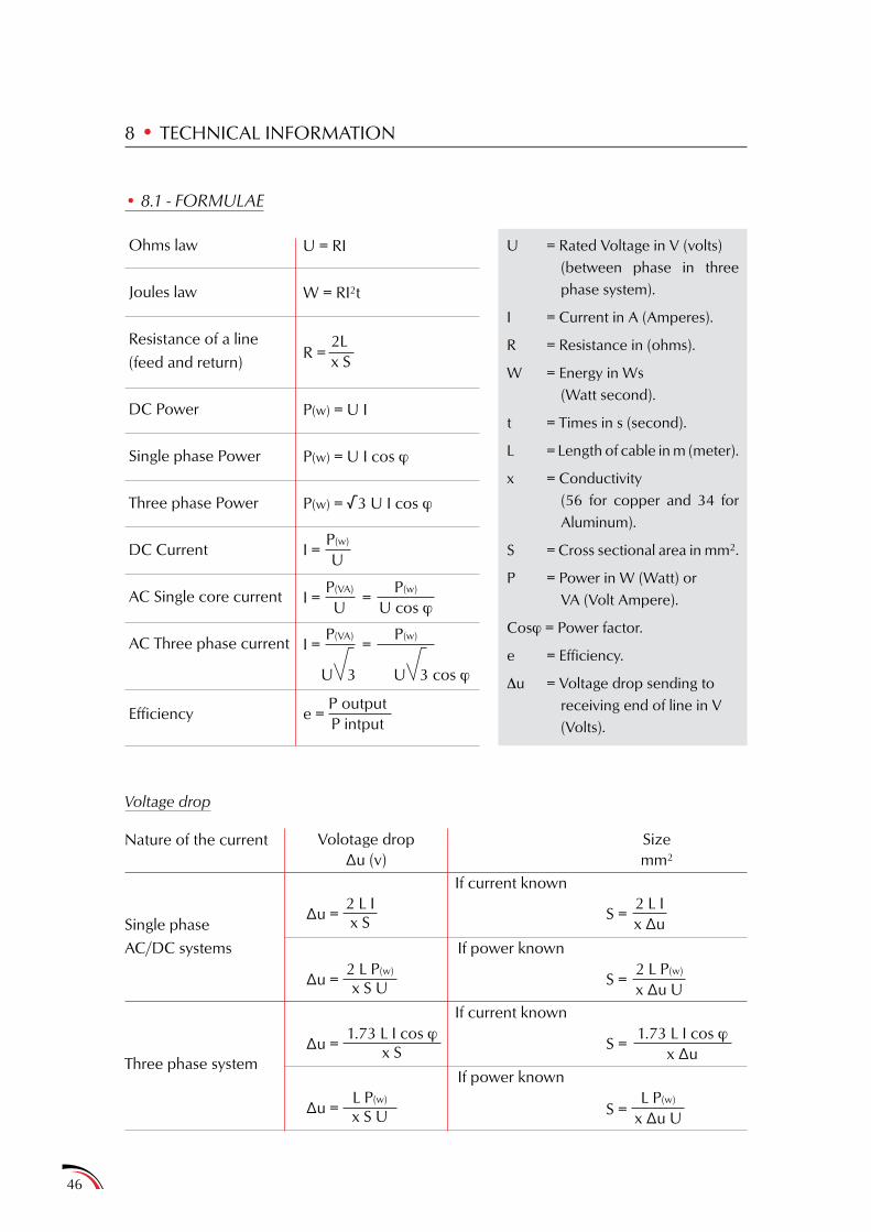
46
• 8.1 - FORMULAE
Ohms law
Joules law
Resistance of a line(feed and return)
DC Power
Single phase Power
Three phase Power
DC Current
AC Single core current
AC Three phase current
Efficiency
Voltage drop
Nature of the current
Single phaseAC/DC systems
Three phase system
8 • TECHNICAL INFORMATION
U = Rated Voltage in V (volts)(between phase in three phase system).
I = Current in A (Amperes).
R = Resistance in (ohms).
W = Energy in Ws(Watt second).
t = Times in s (second).
L = Length of cable in m (meter).
x = Conductivity(56 for copper and 34 for Aluminum).
S = Cross sectional area in mm2.
P = Power in W (Watt) orVA (Volt Ampere).
Cosj = Power factor.
e = Efficiency.
Du = Voltage drop sending to receiving end of line in V (Volts).
U = RI
W = RI2t
P(w) = U I
P(w) = U I cos j
P(w) = √3 U I cos j
2Lx SR =
I =P(w)
U
∆u =2 L Ix S
∆u =1.73 L I cos j
x S S =1.73 L I cos j
x ∆u
∆u =2 L P(w)
x S U
∆u =L P(w)
x S U
S =2 L P(w)
x ∆u U
S =L P(w)
x ∆u U
S =2 L Ix ∆u
e =P outputP intput
Volotage drop∆u (v)
Sizemm2
If current known
If power known
If current known
If power known
I = =P(VA)
UP(w)
U cos j
I = =P(VA)
U U3
P(w)
3 cos j
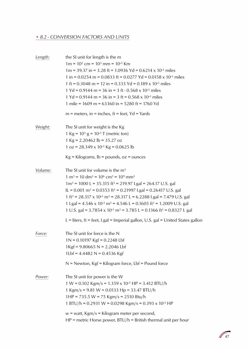
47
• 8.2 - CONVERSION FACTORS AND UNITS
Length: the SI unit for length is the m 1m = 102 cm = 103 mm = 10-3 Km 1m = 39.37 in = 3.28 ft = 1.0936 Yd = 0.6214 x 10⁻³ miles 1 in = 0.0254 m = 0.0833 ft = 0.0277 Yd = 0.0158 x 10⁻³ miles 1 ft = 0.3048 m = 12 in = 0.333 Yd = 0.189 x 10⁻³ miles 1 Yd = 0.9144 m = 36 in = 3 ft - 0.568 x 10⁻³ miles 1 Yd = 0.9144 m = 36 in = 3 ft = 0.568 x 10⁻³ miles 1 mile = 1609 m = 63360 in = 5280 ft = 1760 Yd
m = meters, in = inches, ft = feet, Yd = Yards
Weight: The SI unit for weight is the Kg 1 Kg = 103 g = 10-3 T (metric ton) 1 Kg = 2.20462 lb = 35.27 oz 1 oz = 28.349 x 10⁻³ Kg = 0.0625 lb
Kg = Kilograms, lb = pounds, oz = ounces
Volume: The SI unit for volume is the m3
1 m3 = 10 dm3 = 106 cm3 = 109 mm3
1m3 = 1000 L = 35.315 ft3 = 219.97 I.gal = 264.17 U.S. gal IL = 0.001 m3 = 0.0353 ft3 = 0.21997 I.gal = 0.26417 U.S. gal 1 ft3 = 28.317 x 10⁻³ m3 = 28.317 L = 6.2288 I.gal = 7.479 U.S. gal 1 I.gal = 4.546 x 10⁻³ m3 = 4.546 L = 0.1605 ft3 = 1.2009 U.S. gal 1 U.S. gal = 3.7854 x 10⁻³ m3 = 3.785 L = 0.1366 ft3 = 0.8327 I. gal
L = liters, ft = feet, I.gal = Imperial gallon, U.S. gal = United States gallon
Force: The SI unit for force is the N 1N = 0.10197 Kgf = 0.2248 Lbf 1Kgf = 9.80665 N = 2.2046 Lbf 1Lbf = 4.4482 N = 0.4536 Kgf
N = Newton, Kgf = Kilogram force, Lbf = Pound force
Power: The SI unit for power is the W 1 W = 0.102 Kgm/s = 1.359 x 10⁻³ HP = 3.412 BTU/h 1 Kgm/s = 9.81 W = 0.0133 Hp = 33.47 BTU/h 1HP = 735.5 W = 75 Kgm/s = 2510 Btu/h 1 BTU/h = 0.2931 W = 0.0298 Kgm/s = 0.393 x 10⁻³ HP
w = watt, Kgm/s = Kilogram meter per second, HP = metric Horse power, BTU/h = British thermal unit per hour
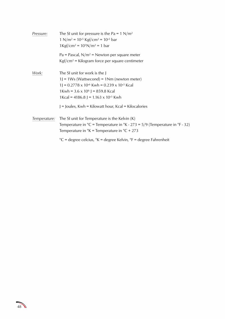
Pressure: The SI unit for pressure is the Pa = 1 N/m2
1 N/m2 = 10-5 Kgf/cm2 = 10-5 bar 1Kgf/cm2 = 105N/m2 = 1 bar
Pa = Pascal, N/m2 = Newton per square meter Kgf/cm2 = Kilogram force per square centimeter
Work: The SI unit for work is the J 1J = 1Ws (Wattsecond) = 1Nm (newton meter) 1J = 0.2778 x 10⁻⁶ Kwh = 0.239 x 10⁻³ Kcal 1Kwh = 3.6 x 10⁶ J = 859.8 Kcal 1Kcal = 4186.8 J = 1.163 x 10⁻³ Kwh
J = Joules, Kwh = Kilowatt hour, Kcal = Kilocalories
Temperature: The SI unit for Temperature is the Kelvin (K) Temperature in °C = Temperature in °K - 273 = 5/9 (Temperature in °F - 32) Temperature in °K = Temperature in °C + 273
°C = degree celcius, °K = degree Kelvin, °F = degree Fahrenheit
48